EP1081627A2 - Medical diagnostic system service connectivity method and apparatus - Google Patents
Medical diagnostic system service connectivity method and apparatus Download PDFInfo
- Publication number
- EP1081627A2 EP1081627A2 EP00307194A EP00307194A EP1081627A2 EP 1081627 A2 EP1081627 A2 EP 1081627A2 EP 00307194 A EP00307194 A EP 00307194A EP 00307194 A EP00307194 A EP 00307194A EP 1081627 A2 EP1081627 A2 EP 1081627A2
- Authority
- EP
- European Patent Office
- Prior art keywords
- connectivity
- service facility
- diagnostic
- service
- systems
- Prior art date
- Legal status (The legal status is an assumption and is not a legal conclusion. Google has not performed a legal analysis and makes no representation as to the accuracy of the status listed.)
- Withdrawn
Links
Images


Classifications
-
- G—PHYSICS
- G16—INFORMATION AND COMMUNICATION TECHNOLOGY [ICT] SPECIALLY ADAPTED FOR SPECIFIC APPLICATION FIELDS
- G16H—HEALTHCARE INFORMATICS, i.e. INFORMATION AND COMMUNICATION TECHNOLOGY [ICT] SPECIALLY ADAPTED FOR THE HANDLING OR PROCESSING OF MEDICAL OR HEALTHCARE DATA
- G16H40/00—ICT specially adapted for the management or administration of healthcare resources or facilities; ICT specially adapted for the management or operation of medical equipment or devices
- G16H40/40—ICT specially adapted for the management or administration of healthcare resources or facilities; ICT specially adapted for the management or operation of medical equipment or devices for the management of medical equipment or devices, e.g. scheduling maintenance or upgrades
-
- G—PHYSICS
- G16—INFORMATION AND COMMUNICATION TECHNOLOGY [ICT] SPECIALLY ADAPTED FOR SPECIFIC APPLICATION FIELDS
- G16H—HEALTHCARE INFORMATICS, i.e. INFORMATION AND COMMUNICATION TECHNOLOGY [ICT] SPECIALLY ADAPTED FOR THE HANDLING OR PROCESSING OF MEDICAL OR HEALTHCARE DATA
- G16H40/00—ICT specially adapted for the management or administration of healthcare resources or facilities; ICT specially adapted for the management or operation of medical equipment or devices
- G16H40/60—ICT specially adapted for the management or administration of healthcare resources or facilities; ICT specially adapted for the management or operation of medical equipment or devices for the operation of medical equipment or devices
- G16H40/67—ICT specially adapted for the management or administration of healthcare resources or facilities; ICT specially adapted for the management or operation of medical equipment or devices for the operation of medical equipment or devices for remote operation
-
- Y—GENERAL TAGGING OF NEW TECHNOLOGICAL DEVELOPMENTS; GENERAL TAGGING OF CROSS-SECTIONAL TECHNOLOGIES SPANNING OVER SEVERAL SECTIONS OF THE IPC; TECHNICAL SUBJECTS COVERED BY FORMER USPC CROSS-REFERENCE ART COLLECTIONS [XRACs] AND DIGESTS
- Y10—TECHNICAL SUBJECTS COVERED BY FORMER USPC
- Y10S—TECHNICAL SUBJECTS COVERED BY FORMER USPC CROSS-REFERENCE ART COLLECTIONS [XRACs] AND DIGESTS
- Y10S128/00—Surgery
- Y10S128/903—Radio telemetry
-
- Y—GENERAL TAGGING OF NEW TECHNOLOGICAL DEVELOPMENTS; GENERAL TAGGING OF CROSS-SECTIONAL TECHNOLOGIES SPANNING OVER SEVERAL SECTIONS OF THE IPC; TECHNICAL SUBJECTS COVERED BY FORMER USPC CROSS-REFERENCE ART COLLECTIONS [XRACs] AND DIGESTS
- Y10—TECHNICAL SUBJECTS COVERED BY FORMER USPC
- Y10S—TECHNICAL SUBJECTS COVERED BY FORMER USPC CROSS-REFERENCE ART COLLECTIONS [XRACs] AND DIGESTS
- Y10S128/00—Surgery
- Y10S128/904—Telephone telemetry
Definitions
- the present invention relates generally to systems and techniques for providing remote service to medical diagnostic equipment and facilities. More particularly, the invention relates to a technique for verifying continued connectivity between a remote service facility and a subscribing medical diagnostic facility or system.
- imaging systems encompass a range of modalities, each characterized by the physics involved in acquiring and processing image data.
- medical diagnostic imaging modalities include magnetic resonance imaging (MRI) systems, x-ray systems, both digital and conventional film-based, computed tomography (CT) systems, ultrasound systems, positron emission tomography (PET) systems, and so forth.
- MRI magnetic resonance imaging
- CT computed tomography
- PET positron emission tomography
- Medical facilities, hospitals and clinics make use of a wide range of such equipment, including more than one of the modalities, and in certain cases, more than one system within each modality. In larger facilities, these systems may be networked in a radiology department to permit common management or control.
- Such systems are increasingly associated with picture archiving and communications systems (PACS) for storing digitized image data for subsequent retrieval and reconstruction of useful images.
- PACS picture archiving and communications systems
- teleradiology applications are on the rise, in which such digitized data may be transmitted to remote locations, such as for review and diagnosis by specialized physicians and radiologists.
- medical diagnostic systems are often a key element in the diagnosis and treatment of disease and ailments. While certain facilities may offer their services during specific periods during the day, others require continued access to the diagnostic equipment in very demanding schedules. In both cases, the facility has a critical interest in maintaining the diagnostic equipment in good operational condition. However, due to the complexity of the systems, personnel required to review and evaluate potential problems as they arise are not often present at the location where the systems are found. Consequently, remote servicing of medical diagnostic equipment has become an important tool in maintaining the systems.
- Improvements in computer networks have greatly facilitated the task of offering assistance to medical diagnostic equipment and facilities.
- network technologies have facilitated proactive techniques wherein the service center may contact the medical diagnostic equipment or facility to check the status of subscribing equipment.
- a remote service facility can interactively receive messages via a network, and can respond automatically to the messages either in a single connection session or in a subsequent session. Data required to analyze the state of operation of the medical diagnostic equipment can be transferred during the initial or subsequent sessions.
- the technique greatly facilitates identification of system problems, allows questions to be posed to the subscribing service provider, facilitates transfer of updates and imaging protocols, and permits standard and customized reports to be transmitted to subscribing systems.
- the interactive aspect of the technique allows the medical diagnostic facility to remain current on services provided by the remote service facility and to communicate at will with the service facility.
- the present invention provides a connectivity verification technique designed to respond to these needs.
- the technique may be employed with any of a variety of diagnostic equipment, including specific systems of various modalities and centralized management systems, such as those typically found in large radiology departments. Where the diagnostic system is connectable to a remote service facility, the technique permits the service facility to verify that the connection can be established, both originating from the service facility and from the diagnostic equipment. Such connections may be made with specific systems, with management systems networked to the diagnostic systems at a specific facility, or both.
- the connectivity verification may be timed or scheduled for automatic implementation, or could be performed manually.
- the system may be designed to provide at least some degree of diagnostic capabilities in which the type or location of connectivity problem is detected and recorded.
- Results of connectivity verifications can be stored and used to evaluate the operability of the overall system, and to improve the system where needed.
- the system may permit notification via an operator, or via automated schemes, including electronic messaging, paging, and so forth.
- the system may be adapted both for stationary diagnostic systems, as well as for mobile systems. In the case of mobile systems, the system may be adapted to await contact of the service facility by the mobile equipment.
- the technique is particularly well suited to interactive service systems in which a diagnostic facility may contact a remote service provider and a remote service provider may contact the diagnostic facility.
- the system is especially adaptable to service arrangements in which subscriptions or licenses are established between the service facility and the diagnostic equipment. Based upon such subscriptions, the service facility insures the connectivity between the diagnostic equipment and the service provider to allow the service provider to be contacted by the equipment managers, or automatically by the system without operator intervention.
- a medical diagnostic and service arrangement designated generally by the reference numeral 10, is illustrated as including a plurality of medical diagnostic systems or stations, and a remote service facility connected by a network link.
- arrangement 10 includes diagnostic equipment provided in a central facility or institution 12, along with independent diagnostic systems 14, and mobile diagnostic systems 16 and 18.
- the various systems, including those within facility 12, are configured to be selectively linked to a remote service facility 20.
- Service facility 20 is contacted by the systems, and may contact the systems, as required, to provide service to the systems and facilities, to address concerns or service requests transmitted from the various systems and equipment, access data from the systems, transmit data to the systems, and so forth.
- arrangement 10 may include any of a variety of medical diagnostic systems of various modalities.
- the remote service facility 20 may provide service to magnetic resonance imaging (MRI) systems, computed tomography (CT) systems, positron emission tomography (PET) systems, ultrasound systems, x-ray systems, and so forth.
- MRI magnetic resonance imaging
- CT computed tomography
- PET positron emission tomography
- the remote service facility may provide similar services to centralized medical diagnostic management systems, picture archiving and communications systems (PACS), teleradiology systems, and so forth.
- Such systems will typically be either stationary (i.e., located in a known place and available by a known network address) or mobile (i.e., movable and susceptible to positioning at various configurable network addresses).
- certain of the diagnostic equipment may be situated in a single facility or institution as shown diagramatically for institution 12.
- three such diagnostic systems 22, 24 and 26 are provided in the institution.
- these systems may be similar in modality or configuration, or may be of different modalities and configurations.
- each of the imaging systems may be of a different type to provide various options to the diagnosing physicians and radiologists for imaging various anatomies and subjects of interest.
- the systems may be networked within the facility, such as through a centralized radiology management system 28.
- Radiology management system 28 may permit the facility to monitor activities, performance, configurations, and other data from the diagnostic systems.
- Radiology management system 28 will include one or more operator work stations 30 for interfacing with the management data and software. As will be appreciated by those skilled in the art, similar operator interfaces will typically be provided for each diagnostic system 22, 24 and 26, permitting a radiologist or clinician to request and configure various examinations, to review examination results, process acquired and stored data files, and so forth. Radiology management system 28 is further provided with communications components permitting it to send and receive data over a communications link as indicated generally at reference numeral 32. Similar communications links may be provided for each of the diagnostic systems within the facility, as indicated at reference numeral 34. As described in greater detail below, these links permit data to be transferred to and from the systems over an open or dedicated network.
- independent diagnostic systems 14 may be provided in the arrangement 10.
- independent clinics and departments within hospitals and institutions may possess one or more such independent diagnostic systems which may be coupled directly to the remote service facility via a communications link 36.
- mobile diagnostic systems 16 and 18 may be linked directly to the remote service facility via links 38.
- such mobile diagnostic systems may include equipment of various modalities, such as MRI or x-ray systems which may be displaced to locations to better service patient populations.
- arrangement 10 may include a series of field engineer stations 40 and 42 which may be similarly linked to the remote service facility to permit field service engineers to exchange data, images, schedules, reports, and the like, with the remote service facility. Such field engineers may be dispatched, for example, to respond to particular needs of subscribing systems as these arise.
- Each of the systems and stations illustrated in Fig. 1 may be linked selectively to the remote service facility via a network as represented generally at reference numeral 44.
- any acceptable network may be employed, including open and dedicated networks, virtual private networks, the Internet, and so forth.
- the communications links to the network may be of any acceptable type, including conventional telephone links, cable modem links, digital subscriber lines and the like.
- Each of the systems is provided with communications interface hardware and software of generally known design, permitting them to establish network links with the remote service facility, and to exchange data with the facility.
- the systems are provided with interactive software by which messages, image data, service requests, system status information, protocols, and so forth may be transmitted to and from the system by establishment of the network connection. Where desired, during periods when no such data is exchanged between the remote service facility and the subscribing system, the network connection may be terminated.
- Remote service facility 20 in the diagrammatical view of Fig. 1, includes both communications components as well as components for managing provision of service to the medical diagnostic systems.
- a series of modems 46 are provided for establishing the network connection needed for the remote service, and for exchanging data over network 44.
- the modems are coupled to communications interface components as designated generally at reference numeral 48.
- these components and modems may include hardware and software for screening communications between the remote service facility and the medical diagnostic systems, including fire walls.
- the modems and communications interface components may be replaced, where appropriate, with alternative communications hardware and software, such as cable modems.
- Communications interface components 48 are coupled to a router 50 for appropriately directing communications to and from the medical diagnostic systems coupled to the service facility via the network.
- Service facility 20 is equipped to handle a variety of service requests and functions both at the initiation of the subscribing diagnostic systems, as well as by the service facility itself.
- a server 52 is illustrated for providing the service functionalities described herein.
- a variety of such servers may be interlinked for various service functions, including receiving and directing service requests, proactively accessing subscribing systems for system status data, managing subscribing system licenses, and generating reports and messages for transmission to the subscribing systems. Certain of the servers may be protected by firewalls to limit access to data.
- Server 52 may be coupled to one or more databases 54 for storing information related to the provision of services to the various subscribing medical diagnostic systems.
- Databases 54 may also store information relating to performance of the systems, system configurations, system license and account data, and so forth.
- a series of work stations 56 may be further linked to server 52, permitting service facility engineers to access data and address service concerns. By way of example, such work stations may be used to trouble shoot potential connectivity problems identified by the procedure described below.
- additional databases or systems as represented generally at reference numeral 58 in Fig. 1, may be linked to the service facility to store or archive data for the systems subscribing to service from the facility. Certain of the remote facilities may be linked in similar ways in various geographical locations, such as around a single region or country, or around the world. Databases 58 may further include statistical information gathered from a population of diagnostic systems for use in analysis and service to similar systems.
- the systems of arrangement 10 are interactively linked to the service facility, it has been found desirable to provide a means for verifying that the systems can connect to the service facility at will and, conversely, that the service facility can readily access the subscribing medical diagnostic systems.
- the inability to contact the service facility may result in delay in addressing the service concerns.
- alternative and potentially time consuming measures must be taken to provide the desired feedback.
- the present technique provides a mechanism for insuring connectivity between the medical diagnostic systems and the service facility.
- Fig. 2 illustrates, certain of the functional components of the diagnostic systems and of the service facility designed to provide verification of connectivity.
- the components are specifically designed to enable connections initiating from either the medical diagnostic equipment or from the remote service facility.
- both the subscribing equipment and the service facility include network servers and server software designed to provide for interactive exchange of data via the network link.
- Such servers may be based on any known or suitable software or protocol, exchanging data, for example, in accordance with Point-to-Point Protocol (PPP), employing Internet Protocol (IP) packets, HyperText Transfer Protocol (HTTP), and so forth.
- PPP Point-to-Point Protocol
- IP Internet Protocol
- HTTP HyperText Transfer Protocol
- the servers of the systems and of the service facility are preferably designed to process and transfer data in raw or processed form, such as image data processed into a standard DICOM format.
- the servers are preferably equipped to support HTTP applications, and include a browser capable of displaying interactive pages, such as in HTML, XTL, or other language configurations, and to support java applications, applets, servlets and similar code for carrying out the functions described herein.
- the subscribing diagnostic system includes a system server 60 which calls upon a connectivity servlet 62 for verifying the status of communications components.
- servlet 62 may be defined by any appropriate code installed at the system or transferred to the system upon demand.
- the servlet will be called upon in response to receipt of a connectivity verification message from the remote service facility, and will thereafter recontact the service facility to verify that the two-way connections can be readily established.
- the connectivity servlet is adapted to contact the service facility upon displacement of the mobile system to a new location, and to receive a verification response to the initiated contact.
- one or more servers 52 are equipped with a series of software modules designed to initiate and respond to connectivity verification messages.
- the server includes a connectivity application 64 which manages the connectivity functions described below.
- a scheduler module 66 defines timing and contacts initiated by the remote service facility for the connectivity verification sequences of subscribing medical diagnostic systems.
- a connectivity check-in module 68 serves to receive and exchange data with diagnostic systems during the connectivity sequences executed by application 64 in accordance with the schedules established by module 66.
- a similar mobile check-in module 70 manages exchange of data with mobile diagnostic systems upon initiation of connectivity verification sequences with those systems.
- Server 52 and the coded modules accessed by it are further interfaced with blocks of memory for storing data used in the connectivity verification process.
- blocks of memory may be defined in any acceptable medium, such as disc drives, magnetic tape, optical memory devices, solid state memory, and so forth.
- memory blocks are provided for mobile sites, as indicated at reference numeral 71, storing configuration parameters for subscribing mobile sites, as well as system identifications, locations, access or address numbers and codes, and so forth.
- a license memory block 72 stores data indicative of the status of current service licenses for the various systems, which may include both accounting data, such information as date information, expire information, and level of service access.
- a log/event memory block 73 is provided to store the results of the connectivity verification sequences executed between the service center and the various subscribing systems. As indicated below, the memory block will generally include historical data indicative of the results of connectivity verification sequences. The memory block may also include references to specific events, scheduled service, service requests, and so forth.
- An alert log block 74 is provided for storing alerts generated by the present technique in response to a failure or anomaly in the connectivity verification sequence. Such alerts may be used to generate dispatches for service engineers both in the field and at the remote service facility to trouble shoot the communications and connection components when connectivity problems arise.
- An alert module 75 serves to generate alerts in response to problems with connectivity, such as electronic messages, pages, service dispatches, and the like.
- An analysis module 76 provides analytical capabilities, such as for recognizing patterns in connectivity problems for specific systems, or for populations of systems based upon historical records of connections and results of connectivity verification sequences.
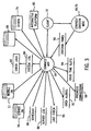
- Fig. 3 represents certain of the foregoing components and, generally, the types of data exchange between the components.
- the connectivity application 64 provided at the remote service facility is designed to exchange data with external clients 12 in the form of medical diagnostic systems. It should be noted that the connectivity verification process is designed to insure that such data can be interactively exchanged both from the service facility to the diagnostic system, and visa-versa.
- the client station therefor is designed to contact and send data to connectivity check-in module 68 or 70 (depending upon the stationary or mobile nature of the client).
- connectivity application 64 is designed to exchange data with an interactive software platform 80 which facilitates the exchange of service data between the remote service facility and the subscribing systems.
- platform 80 may provide for direct or indirect interface between actual modality components, such as MRI or CT scanners, x-ray imaging stations, and ultrasound imaging stations.
- the platform may also provide various service functionalities, including electronic messaging, receipt and handling of service requests and questions, image evaluation, imaging and processing protocol exchange, system configuration and data exchange, and so forth.
- a log module 82 is written into by connectivity application 64 to store system log information as indicated at reference numeral 84.
- log information will typically include records of connectivity verification checks, events, service requests, and the like.
- Connectivity application 64 also draws upon schedule data as indicated at reference numeral 86 to identify which subscribing systems should be contacted and at what times of the day or night. As described below, because certain systems may be active or inactive at specific periods, or may be located in various time zones, the technique facilitates verification checks at various time intervals depending upon system availability and responsiveness.
- Server log data 88 is also accessed by connectivity application 64 for review of server activities. Data indicative of the most recent verification sequence results are stored and accessed as indicated at reference numeral 90.
- a log of open alerts, 92 may be accessed by connectivity application 64 as such alerts are generated, particularly as a result of failure or anomalies in the connectivity sequence as described below.
- a log of time slots 94 stores data indicative of the time periods during which connectivity verification sequences have been used successfully and unsuccessfully for specific subscribing systems.
- a log of verification or "check-in" times 96 is kept as a record of responsiveness of the subscribing systems to connectivity verification messages from the service facility, as well as mobile system-initiated verification sequences.
- a log of previous connections 98 may be accessed by application 64, and may serve as a basis for scheduling verification sequences, as described below.
- a statistical database 99 is kept with data for systems served by application 64, including connectivity statistics. It should be noted that the logical overview of Fig. 3 is provided for exemplary purposes only, and modules, memory designations, logs, and the like for specific systems may be tailored in accordance with system needs and architecture.
- the present system is designed to automatically verify status of communications components for systems subscribing to remote service from the service facility.
- automatic connectivity verification sequences may be initiated for specific subscriptions, or for all subscribing systems.
- the service facility provides for interactive service arrangements with specific systems, such verification checks may be initiated and carried out on a regular or a scheduled basis.
- the service facility may provide more limited offerings which do not require such connectivity verifications, or require verifications of a limited nature or on a more limited schedule.
- Figs. 4 and 5 illustrate exemplary steps in control logic implemented by code at the service facility for carrying out the automatic connectivity verification techniques.
- Fig. 4 represents exemplary steps for verification of connectivity between the service center and systems of known location, typically situated in institutions, clinics, hospitals, and so forth.
- the control logic of Fig. 4, represented generally by reference numeral 100 begins at step 102 wherein a system is selected for contact. In the presently contemplated embodiment, the system is selected based upon known parameters, such as system availability, time slots for the system availability, the nature of the system, license arrangements for the provision of services to the system, system identification and address, and so forth. In general, schedules for connectivity verification may be established in advance and performed automatically.
- the schedule may be at least partially based upon recent historical connections between systems and a service facility, with systems having more recently contacted the service facility being moved to a lower priority. Conversely, where historical usage data indicate that a system would have been expected to contact the service facility within a specified time or at a known frequency, such systems may be moved up in priority of scheduling. Based upon such information, the system is contacted at step 104. The contact may be made over any suitable network, typically at present over a conventional telephony line via a modem.
- the connectivity application determines whether the contact has been successfully established. If the contact is not successfully established, the system may be configured to retry the network connection as indicated at step 108. Moreover, the number of attempts to establish the connection, and the time between such attempts, may be configured by the service facility. Where such subsequent attempts are available and desired, the system will attempt such recontact by cycling back to step 104. If, at step 106, the contact is successfully established, control advances to step 110.
- the contact is unsuccessful at step 106, various measures may be taken.
- the inability to establish contact may be due to one of a number of factors, including the status of the diagnostic system itself, the state of transmission lines, communications hardware, software, and interface components. Moreover, for certain systems, the communications components may be occupied or simply unavailable at the period of time in which the verification sequence is initiated. If the number of attempts permitted at step 108 is exhausted, an alert is generated as indicated at step 112.
- the alert is stored on an alert log 74 (see Fig. 2) and may be accessed by the service facility, such as to generate a dispatch for a service engineer or to prompt operator intervention in contacting the subscribing system to investigate the nature of the connectivity problem.
- the failure of the connectivity sequence is recorded in a log/event memory 73 (see Fig. 2).
- step 110 data is transmitted between the service facility and the subscribing diagnostic system, as indicated at step 110.
- relatively short messages are transmitted at this step, to avoid unnecessarily occupying either the service facility or the subscribing system.
- the data will be sufficient to provoke the code at the subscribing system to call upon the connectivity servlet and to attempt to re-establish contact with the service facility after the connection is dropped.
- the connectivity application determines whether the data has been successfully transmitted to the subscribing system. If the data has not been successfully transmitted to the system, an alert is generated at step 118, signaling to service center personnel that an inquiry should be made into the nature of the problem prohibiting the transfer of the data. The alert is stored in an alert log at the service facility. In addition, the failure of the connectivity verification sequence is recorded at step 120. If, on the other hand, the data is successfully transmitted at step 116, the service facility interrupts the connection as indicated at step 122. It should be noted that the present technique may be employed for detecting and analyzing the status of connectivity over more than one connection line. Thus, where desired, the connection established at step 104 may be disconnected as indicated at step 122, or may remain connected while the medical diagnostic system recontacts the service facility via an alternative communications route.
- the connectivity application awaits a return message from the subscribing system contacted.
- the connectivity servlet on the subscribing system is configured to return the call initiated by the service facility to verify that two-way connectivity is functional.
- the service center awaits the return call during a configurable window of time. If the wait period times out prior to receiving the call back from the subscribing system, the foregoing steps in the sequence may be repeated as indicated at step 126. Again, the number of cycles through the connectivity sequence may be set in advance. Under normal circumstances, a call is received from the subscribing system and the resulting success of the connectivity verification is recorded at step 128.
- alerts may take the form, for example, of electronic messages to service personnel, pages to service personnel, service dispatches, and so forth.
- the connectivity sequence is attempted in one of three time periods distributed through a 24 hour period. If the results of the sequence summarized in Fig. 4 indicate that connection cannot be achieved at a specific time slot, an alternative time slot may be scheduled for the system-specific connectivity check sequence.
- control logic designated generally by the reference numeral 200, begins at step 202 wherein the diagnostic system is relocated or positioned at a desired location.
- the connectivity servlet at the diagnostic system determines whether a system check-in has been performed within a desired amount of time, such as subsequent to the relocation. If the check-in has been performed, the logic may be exited as indicated at step 206. If no such connectivity verification has been performed, or has not been performed within a desired amount of time, or since relocation of the system, the server at the diagnostic system initiates a network connection with the service center as indicated at step 208.
- system data is transmitted at step 110, identifying the subscribing system, its location, its network address or call number, and so forth, It should be noted that, although not represented in Fig. 5, intervening logical steps may be included in this routine for signaling that a contact could not be established at step 208 or that data could not be successfully transmitted at step 210. In either event, an alert and failure event may be recorded.
- the mobile diagnostic system interrupts the network connection at step 212.
- the service facility In response to the data received from the mobile diagnostic system, the service facility recontacts the system, as indicated at step 214.
- the server at the mobile diagnostic system may also be configured to await a specific amount of time for the verification call back as indicated above in the logic of Fig. 4.
- the service facility determines, at step 216, whether the network connection could be successfully established with the mobile system. If not, the connectivity application at the service facility may be configured to reattempt the network connection as indicated at step 218. If such attempts to recontact the system are unsuccessful, or if a desired number of reattempts expires, control advances to step 220 where an alert is generated, indicating that the connectivity verification sequence identified a connectivity failure and that additional service may be required.
- the results of the connectivity, verification sequence are recorded.
- the system location is recorded for the purposes of any further contact which may need to be established between the service center and the subscribing mobile system.
- the foregoing logic provides several levels of identification of connectivity problems or failures. Specifically, because connectivity failures may involve hardware or software difficulties at various locations in the network connection, data, transfer, receipt and processing components, and so forth, it has been found useful to provide as much information in identifying a connectivity failure as possible. Such indications greatly facilitate troubleshooting of the connectivity components, providing service personnel with a clear indication of which portions of the system may be functional and which may need review, even without requiring direct involvement of personnel at the location of the system. For example, in a present configuration, a variety of failure modes may be detected based upon the point in the logic where the failure took place.
- Such failures may occur, for example, due to the inability of the service facility to contact the subscribing system. Failures at this point may be attributed to hardware or software which is currently occupied at the service facility, hardware or software which is currently occupied at the subscribing system, failure of the subscribing system to respond to a call, failure of the PPP module at the subscribing system to respond, an incorrect IP address, and so forth. Moreover, even once the connection is established, a failure or anomaly in the data transmission may result in identifiable failure modes. Similar failures may occur from an inability of the subscribing system to recontact the service facility. Moreover, failures may occur due to an inability to access an HTTP server or the connectivity servlet. Other events may be similarly recorded, such as the failure of the subscribing system to call back or to call back within a desired time window.
- the connectivity verification and response sequences may be carried out at any convenient time, such as during off-peak hours.
- the scheduled order of performing the verification checks may also be influenced by recent activities (e.g. data exchanges) between specific systems and the service facility. For example, where a system would be scheduled for connectivity verification but recently contacted the service facility, that system may be rescheduled for a later time, freeing the schedule for systems which have not successfully contacted the service facility within a desired time frame.
- the service facility may move the system up on a connectivity verification schedule, considering that the inactivity may be indicative of a problem in the system connectivity hardware or software.
- the results of the connectivity verification sequences may be used for analysis of system and component performance, and for system design or improvement.
Landscapes
- Health & Medical Sciences (AREA)
- Engineering & Computer Science (AREA)
- Biomedical Technology (AREA)
- Business, Economics & Management (AREA)
- General Business, Economics & Management (AREA)
- Epidemiology (AREA)
- General Health & Medical Sciences (AREA)
- Medical Informatics (AREA)
- Primary Health Care (AREA)
- Public Health (AREA)
- Measuring And Recording Apparatus For Diagnosis (AREA)
- Medical Treatment And Welfare Office Work (AREA)
- Computer And Data Communications (AREA)
Abstract
Description
- The present invention relates generally to systems and techniques for providing remote service to medical diagnostic equipment and facilities. More particularly, the invention relates to a technique for verifying continued connectivity between a remote service facility and a subscribing medical diagnostic facility or system.
- In recent years, considerable advances have been made in medical diagnostic equipment and systems, particularly imaging systems. Such imaging systems encompass a range of modalities, each characterized by the physics involved in acquiring and processing image data. At present, medical diagnostic imaging modalities include magnetic resonance imaging (MRI) systems, x-ray systems, both digital and conventional film-based, computed tomography (CT) systems, ultrasound systems, positron emission tomography (PET) systems, and so forth. Medical facilities, hospitals and clinics make use of a wide range of such equipment, including more than one of the modalities, and in certain cases, more than one system within each modality. In larger facilities, these systems may be networked in a radiology department to permit common management or control. Such systems are increasingly associated with picture archiving and communications systems (PACS) for storing digitized image data for subsequent retrieval and reconstruction of useful images. Moreover, teleradiology applications are on the rise, in which such digitized data may be transmitted to remote locations, such as for review and diagnosis by specialized physicians and radiologists.
- Regardless of the particular modality, medical diagnostic systems are often a key element in the diagnosis and treatment of disease and ailments. While certain facilities may offer their services during specific periods during the day, others require continued access to the diagnostic equipment in very demanding schedules. In both cases, the facility has a critical interest in maintaining the diagnostic equipment in good operational condition. However, due to the complexity of the systems, personnel required to review and evaluate potential problems as they arise are not often present at the location where the systems are found. Consequently, remote servicing of medical diagnostic equipment has become an important tool in maintaining the systems.
- Traditionally, remote servicing of medical diagnostic equipment was performed via telephone. Operations personnel would call a remote service facility to report malfunctions and to ask questions regarding the proper operation and settings for the equipment. Where such queries could not be sufficiently handled by telephone, a service engineer was dispatched to troubleshoot the system or to provide the needed assistance.
- Improvements in computer networks have greatly facilitated the task of offering assistance to medical diagnostic equipment and facilities. In particular, rather than simply calling a remote service facility and either talking directly to a technician or engineer, or awaiting a return call from a service center, network technologies have facilitated proactive techniques wherein the service center may contact the medical diagnostic equipment or facility to check the status of subscribing equipment.
- Further advancements have been proposed to providing remote service to medical diagnostic systems in an effort to provide the level of service on a continual and interactive basis needed by many facilities. In one system, a remote service facility can interactively receive messages via a network, and can respond automatically to the messages either in a single connection session or in a subsequent session. Data required to analyze the state of operation of the medical diagnostic equipment can be transferred during the initial or subsequent sessions. The technique greatly facilitates identification of system problems, allows questions to be posed to the subscribing service provider, facilitates transfer of updates and imaging protocols, and permits standard and customized reports to be transmitted to subscribing systems. The interactive aspect of the technique allows the medical diagnostic facility to remain current on services provided by the remote service facility and to communicate at will with the service facility.
- While these advancements in the provision of remote services to medical diagnostic equipment have greatly enhanced the level of service and information exchange, they may be subject to difficulties, particularly those arising from unanticipated connectivity problems. In particular, exchange of service information and requests on an interactive basis assumes that the remote service facility can contact the subscribing systems at will, and, conversely, that the subscribing systems can freely contact the remote service provider. Where systems operate well and no service is needed, extended periods may transpire without a contact of the service facility. If the required connection between the diagnostic equipment and the service facility is inoperative, however, service requests may not be reliably submitted to the service facility, and information from the service facility to the diagnostic system may not arrive properly or in a timely manner. Operator intervention may sometimes detect such problems, but typically only after a needed response has not been received for some time. Such delays would advantageously be avoided to insure that service problems and questions can be addressed in a timely manner.
- There is a need, therefore, for a technique adapted to monitor proper connectivity of medical diagnostic equipment and facilities with a remote service provider. There is, at present, a particular need for a system which can verify two-way connectivity in which a service facility can freely contact a subscribing diagnostic system, and a diagnostic system can contact the service facility.
- The present invention provides a connectivity verification technique designed to respond to these needs. The technique may be employed with any of a variety of diagnostic equipment, including specific systems of various modalities and centralized management systems, such as those typically found in large radiology departments. Where the diagnostic system is connectable to a remote service facility, the technique permits the service facility to verify that the connection can be established, both originating from the service facility and from the diagnostic equipment. Such connections may be made with specific systems, with management systems networked to the diagnostic systems at a specific facility, or both. Moreover, the connectivity verification may be timed or scheduled for automatic implementation, or could be performed manually. The system may be designed to provide at least some degree of diagnostic capabilities in which the type or location of connectivity problem is detected and recorded. Results of connectivity verifications can be stored and used to evaluate the operability of the overall system, and to improve the system where needed. Upon failure of the connectivity test, or when inconsistent or unreliable connectivity is identified, the system may permit notification via an operator, or via automated schemes, including electronic messaging, paging, and so forth. The system may be adapted both for stationary diagnostic systems, as well as for mobile systems. In the case of mobile systems, the system may be adapted to await contact of the service facility by the mobile equipment.
- The technique is particularly well suited to interactive service systems in which a diagnostic facility may contact a remote service provider and a remote service provider may contact the diagnostic facility. In addition, the system is especially adaptable to service arrangements in which subscriptions or licenses are established between the service facility and the diagnostic equipment. Based upon such subscriptions, the service facility insures the connectivity between the diagnostic equipment and the service provider to allow the service provider to be contacted by the equipment managers, or automatically by the system without operator intervention.
- An embodiment of the invention will now be described, by way of example, with reference to the accompanying drawings, in which:
- Fig. 1 is a diagrammatical representation of a series of medical diagnostic systems and facilities linked to a remote service facility over a network;
- Fig. 2 is a diagrammatical representation of certain of the functional components of one of the diagnostic systems shown in Fig. 1 and of the remote service facility;
- Fig. 3 is a data flow diagram illustrating certain of the signals and data exchanged between the service facility and the diagnostic equipment in a connectivity verification scheme in accordance with certain aspects of the invention;
- Fig. 4 is a flow chart illustrating steps in exemplary control logic for performing a connectivity verification scheme; and,
- Fig. 5 is a flow chart illustrating exemplary control logic for connectivity verification with a mobile diagnostic system.
-
- Referring now to Fig. 1, a medical diagnostic and service arrangement, designated generally by the
reference numeral 10, is illustrated as including a plurality of medical diagnostic systems or stations, and a remote service facility connected by a network link. In the diagrammatic representation of Fig. 1,arrangement 10 includes diagnostic equipment provided in a central facility orinstitution 12, along with independentdiagnostic systems 14, and mobilediagnostic systems facility 12, are configured to be selectively linked to aremote service facility 20.Service facility 20 is contacted by the systems, and may contact the systems, as required, to provide service to the systems and facilities, to address concerns or service requests transmitted from the various systems and equipment, access data from the systems, transmit data to the systems, and so forth. - In general,
arrangement 10 may include any of a variety of medical diagnostic systems of various modalities. In the presently contemplated embodiment, for example, theremote service facility 20 may provide service to magnetic resonance imaging (MRI) systems, computed tomography (CT) systems, positron emission tomography (PET) systems, ultrasound systems, x-ray systems, and so forth. Moreover, the remote service facility may provide similar services to centralized medical diagnostic management systems, picture archiving and communications systems (PACS), teleradiology systems, and so forth. Such systems will typically be either stationary (i.e., located in a known place and available by a known network address) or mobile (i.e., movable and susceptible to positioning at various configurable network addresses). - As illustrated in Fig. 1, certain of the diagnostic equipment may be situated in a single facility or institution as shown diagramatically for
institution 12. In the illustrated embodiment, three suchdiagnostic systems radiology management system 28.Radiology management system 28 may permit the facility to monitor activities, performance, configurations, and other data from the diagnostic systems.Radiology management system 28 will include one or moreoperator work stations 30 for interfacing with the management data and software. As will be appreciated by those skilled in the art, similar operator interfaces will typically be provided for eachdiagnostic system Radiology management system 28 is further provided with communications components permitting it to send and receive data over a communications link as indicated generally atreference numeral 32. Similar communications links may be provided for each of the diagnostic systems within the facility, as indicated atreference numeral 34. As described in greater detail below, these links permit data to be transferred to and from the systems over an open or dedicated network. - Various independent
diagnostic systems 14 may be provided in thearrangement 10. In particular, independent clinics and departments within hospitals and institutions may possess one or more such independent diagnostic systems which may be coupled directly to the remote service facility via acommunications link 36. Similarly, mobilediagnostic systems links 38. In general, such mobile diagnostic systems may include equipment of various modalities, such as MRI or x-ray systems which may be displaced to locations to better service patient populations. Finally,arrangement 10 may include a series offield engineer stations - Each of the systems and stations illustrated in Fig. 1 may be linked selectively to the remote service facility via a network as represented generally at
reference numeral 44. For the purposes of the present technique, any acceptable network may be employed, including open and dedicated networks, virtual private networks, the Internet, and so forth. Moreover, the communications links to the network may be of any acceptable type, including conventional telephone links, cable modem links, digital subscriber lines and the like. Each of the systems is provided with communications interface hardware and software of generally known design, permitting them to establish network links with the remote service facility, and to exchange data with the facility. In the presently preferred configuration, the systems are provided with interactive software by which messages, image data, service requests, system status information, protocols, and so forth may be transmitted to and from the system by establishment of the network connection. Where desired, during periods when no such data is exchanged between the remote service facility and the subscribing system, the network connection may be terminated. -
Remote service facility 20, in the diagrammatical view of Fig. 1, includes both communications components as well as components for managing provision of service to the medical diagnostic systems. Thus, a series ofmodems 46 are provided for establishing the network connection needed for the remote service, and for exchanging data overnetwork 44. The modems are coupled to communications interface components as designated generally atreference numeral 48. As will be appreciated by those skilled in the art, these components and modems may include hardware and software for screening communications between the remote service facility and the medical diagnostic systems, including fire walls. Also, the modems and communications interface components may be replaced, where appropriate, with alternative communications hardware and software, such as cable modems.Communications interface components 48 are coupled to arouter 50 for appropriately directing communications to and from the medical diagnostic systems coupled to the service facility via the network. -
Service facility 20 is equipped to handle a variety of service requests and functions both at the initiation of the subscribing diagnostic systems, as well as by the service facility itself. In the illustrated embodiment, aserver 52 is illustrated for providing the service functionalities described herein. In practice, a variety of such servers may be interlinked for various service functions, including receiving and directing service requests, proactively accessing subscribing systems for system status data, managing subscribing system licenses, and generating reports and messages for transmission to the subscribing systems. Certain of the servers may be protected by firewalls to limit access to data.Server 52 may be coupled to one ormore databases 54 for storing information related to the provision of services to the various subscribing medical diagnostic systems.Databases 54 may also store information relating to performance of the systems, system configurations, system license and account data, and so forth. A series ofwork stations 56 may be further linked toserver 52, permitting service facility engineers to access data and address service concerns. By way of example, such work stations may be used to trouble shoot potential connectivity problems identified by the procedure described below. Finally, additional databases or systems, as represented generally atreference numeral 58 in Fig. 1, may be linked to the service facility to store or archive data for the systems subscribing to service from the facility. Certain of the remote facilities may be linked in similar ways in various geographical locations, such as around a single region or country, or around the world.Databases 58 may further include statistical information gathered from a population of diagnostic systems for use in analysis and service to similar systems. - Because the systems of
arrangement 10 are interactively linked to the service facility, it has been found desirable to provide a means for verifying that the systems can connect to the service facility at will and, conversely, that the service facility can readily access the subscribing medical diagnostic systems. In general, where a system experiences technical difficulties or where service requests arise, the inability to contact the service facility may result in delay in addressing the service concerns. Similarly, even where service concerns are received from the systems, where the systems cannot be recontacted by the service facility, alternative and potentially time consuming measures must be taken to provide the desired feedback. The present technique provides a mechanism for insuring connectivity between the medical diagnostic systems and the service facility. - Fig. 2 illustrates, certain of the functional components of the diagnostic systems and of the service facility designed to provide verification of connectivity. The components are specifically designed to enable connections initiating from either the medical diagnostic equipment or from the remote service facility. In a presently preferred embodiment, both the subscribing equipment and the service facility include network servers and server software designed to provide for interactive exchange of data via the network link. Such servers may be based on any known or suitable software or protocol, exchanging data, for example, in accordance with Point-to-Point Protocol (PPP), employing Internet Protocol (IP) packets, HyperText Transfer Protocol (HTTP), and so forth. Moreover, the servers of the systems and of the service facility are preferably designed to process and transfer data in raw or processed form, such as image data processed into a standard DICOM format. Finally, the servers are preferably equipped to support HTTP applications, and include a browser capable of displaying interactive pages, such as in HTML, XTL, or other language configurations, and to support java applications, applets, servlets and similar code for carrying out the functions described herein.
- In the diagrammatical representation of Fig. 2, the subscribing diagnostic system includes a
system server 60 which calls upon aconnectivity servlet 62 for verifying the status of communications components. As will be appreciated by those skilled in the art,servlet 62 may be defined by any appropriate code installed at the system or transferred to the system upon demand. As described more fully below, in fixed or stationary systems, the servlet will be called upon in response to receipt of a connectivity verification message from the remote service facility, and will thereafter recontact the service facility to verify that the two-way connections can be readily established. In mobile systems, the connectivity servlet is adapted to contact the service facility upon displacement of the mobile system to a new location, and to receive a verification response to the initiated contact. - Within the remote service facility, one or
more servers 52 are equipped with a series of software modules designed to initiate and respond to connectivity verification messages. In the diagrammatical representation of Fig. 2, the server includes aconnectivity application 64 which manages the connectivity functions described below. Ascheduler module 66 defines timing and contacts initiated by the remote service facility for the connectivity verification sequences of subscribing medical diagnostic systems. A connectivity check-inmodule 68 serves to receive and exchange data with diagnostic systems during the connectivity sequences executed byapplication 64 in accordance with the schedules established bymodule 66. A similar mobile check-inmodule 70 manages exchange of data with mobile diagnostic systems upon initiation of connectivity verification sequences with those systems. -
Server 52 and the coded modules accessed by it are further interfaced with blocks of memory for storing data used in the connectivity verification process. These blocks of memory may be defined in any acceptable medium, such as disc drives, magnetic tape, optical memory devices, solid state memory, and so forth. As illustrated in Fig. 2, memory blocks are provided for mobile sites, as indicated atreference numeral 71, storing configuration parameters for subscribing mobile sites, as well as system identifications, locations, access or address numbers and codes, and so forth. Alicense memory block 72 stores data indicative of the status of current service licenses for the various systems, which may include both accounting data, such information as date information, expire information, and level of service access. A log/event memory block 73 is provided to store the results of the connectivity verification sequences executed between the service center and the various subscribing systems. As indicated below, the memory block will generally include historical data indicative of the results of connectivity verification sequences. The memory block may also include references to specific events, scheduled service, service requests, and so forth. Analert log block 74 is provided for storing alerts generated by the present technique in response to a failure or anomaly in the connectivity verification sequence. Such alerts may be used to generate dispatches for service engineers both in the field and at the remote service facility to trouble shoot the communications and connection components when connectivity problems arise. Analert module 75 serves to generate alerts in response to problems with connectivity, such as electronic messages, pages, service dispatches, and the like. Ananalysis module 76 provides analytical capabilities, such as for recognizing patterns in connectivity problems for specific systems, or for populations of systems based upon historical records of connections and results of connectivity verification sequences. - Fig. 3 represents certain of the foregoing components and, generally, the types of data exchange between the components. As shown in Fig. 3, the
connectivity application 64 provided at the remote service facility is designed to exchange data withexternal clients 12 in the form of medical diagnostic systems. It should be noted that the connectivity verification process is designed to insure that such data can be interactively exchanged both from the service facility to the diagnostic system, and visa-versa. The client station therefor is designed to contact and send data to connectivity check-inmodule 68 or 70 (depending upon the stationary or mobile nature of the client). In addition to the memory blocks represented generally atreference numerals memories connectivity application 64 is designed to exchange data with aninteractive software platform 80 which facilitates the exchange of service data between the remote service facility and the subscribing systems. In the presently preferred embodiment,platform 80 may provide for direct or indirect interface between actual modality components, such as MRI or CT scanners, x-ray imaging stations, and ultrasound imaging stations. The platform may also provide various service functionalities, including electronic messaging, receipt and handling of service requests and questions, image evaluation, imaging and processing protocol exchange, system configuration and data exchange, and so forth. - A
log module 82 is written into byconnectivity application 64 to store system log information as indicated atreference numeral 84. As noted above, such log information will typically include records of connectivity verification checks, events, service requests, and the like.Connectivity application 64 also draws upon schedule data as indicated atreference numeral 86 to identify which subscribing systems should be contacted and at what times of the day or night. As described below, because certain systems may be active or inactive at specific periods, or may be located in various time zones, the technique facilitates verification checks at various time intervals depending upon system availability and responsiveness.Server log data 88 is also accessed byconnectivity application 64 for review of server activities. Data indicative of the most recent verification sequence results are stored and accessed as indicated atreference numeral 90. A log of open alerts, 92, may be accessed byconnectivity application 64 as such alerts are generated, particularly as a result of failure or anomalies in the connectivity sequence as described below. A log oftime slots 94 stores data indicative of the time periods during which connectivity verification sequences have been used successfully and unsuccessfully for specific subscribing systems. A log of verification or "check-in"times 96 is kept as a record of responsiveness of the subscribing systems to connectivity verification messages from the service facility, as well as mobile system-initiated verification sequences. A log ofprevious connections 98 may be accessed byapplication 64, and may serve as a basis for scheduling verification sequences, as described below. Finally, astatistical database 99 is kept with data for systems served byapplication 64, including connectivity statistics, It should be noted that the logical overview of Fig. 3 is provided for exemplary purposes only, and modules, memory designations, logs, and the like for specific systems may be tailored in accordance with system needs and architecture. - As described above, the present system is designed to automatically verify status of communications components for systems subscribing to remote service from the service facility. In general, automatic connectivity verification sequences may be initiated for specific subscriptions, or for all subscribing systems. Thus, where the service facility provides for interactive service arrangements with specific systems, such verification checks may be initiated and carried out on a regular or a scheduled basis. At the same time, the service facility may provide more limited offerings which do not require such connectivity verifications, or require verifications of a limited nature or on a more limited schedule.
- Figs. 4 and 5 illustrate exemplary steps in control logic implemented by code at the service facility for carrying out the automatic connectivity verification techniques. Fig. 4 represents exemplary steps for verification of connectivity between the service center and systems of known location, typically situated in institutions, clinics, hospitals, and so forth. The control logic of Fig. 4, represented generally by
reference numeral 100, begins atstep 102 wherein a system is selected for contact. In the presently contemplated embodiment, the system is selected based upon known parameters, such as system availability, time slots for the system availability, the nature of the system, license arrangements for the provision of services to the system, system identification and address, and so forth. In general, schedules for connectivity verification may be established in advance and performed automatically. Moreover, the schedule may be at least partially based upon recent historical connections between systems and a service facility, with systems having more recently contacted the service facility being moved to a lower priority. Conversely, where historical usage data indicate that a system would have been expected to contact the service facility within a specified time or at a known frequency, such systems may be moved up in priority of scheduling. Based upon such information, the system is contacted atstep 104. The contact may be made over any suitable network, typically at present over a conventional telephony line via a modem. - At
step 106, the connectivity application determines whether the contact has been successfully established. If the contact is not successfully established, the system may be configured to retry the network connection as indicated atstep 108. Moreover, the number of attempts to establish the connection, and the time between such attempts, may be configured by the service facility. Where such subsequent attempts are available and desired, the system will attempt such recontact by cycling back to step 104. If, atstep 106, the contact is successfully established, control advances to step 110. - If the contact is unsuccessful at
step 106, various measures may be taken. The inability to establish contact may be due to one of a number of factors, including the status of the diagnostic system itself, the state of transmission lines, communications hardware, software, and interface components. Moreover, for certain systems, the communications components may be occupied or simply unavailable at the period of time in which the verification sequence is initiated. If the number of attempts permitted atstep 108 is exhausted, an alert is generated as indicated atstep 112. The alert is stored on an alert log 74 (see Fig. 2) and may be accessed by the service facility, such as to generate a dispatch for a service engineer or to prompt operator intervention in contacting the subscribing system to investigate the nature of the connectivity problem. Atstep 114 the failure of the connectivity sequence is recorded in a log/event memory 73 (see Fig. 2). - Once contact is successfully established at
step 106, data is transmitted between the service facility and the subscribing diagnostic system, as indicated atstep 110. In the presently preferred embodiment, relatively short messages are transmitted at this step, to avoid unnecessarily occupying either the service facility or the subscribing system. In general, the data will be sufficient to provoke the code at the subscribing system to call upon the connectivity servlet and to attempt to re-establish contact with the service facility after the connection is dropped. - At
step 116, the connectivity application determines whether the data has been successfully transmitted to the subscribing system. If the data has not been successfully transmitted to the system, an alert is generated atstep 118, signaling to service center personnel that an inquiry should be made into the nature of the problem prohibiting the transfer of the data. The alert is stored in an alert log at the service facility. In addition, the failure of the connectivity verification sequence is recorded atstep 120. If, on the other hand, the data is successfully transmitted atstep 116, the service facility interrupts the connection as indicated atstep 122. It should be noted that the present technique may be employed for detecting and analyzing the status of connectivity over more than one connection line. Thus, where desired, the connection established atstep 104 may be disconnected as indicated atstep 122, or may remain connected while the medical diagnostic system recontacts the service facility via an alternative communications route. - Following the initial contact and transfer of data as summarized above, the connectivity application awaits a return message from the subscribing system contacted. As noted above, the connectivity servlet on the subscribing system is configured to return the call initiated by the service facility to verify that two-way connectivity is functional. Thus, as indicated at
step 124 in Fig. 4, the service center awaits the return call during a configurable window of time. If the wait period times out prior to receiving the call back from the subscribing system, the foregoing steps in the sequence may be repeated as indicated atstep 126. Again, the number of cycles through the connectivity sequence may be set in advance. Under normal circumstances, a call is received from the subscribing system and the resulting success of the connectivity verification is recorded atstep 128. In the event the sequence is repeated, following the permissible number of attempts to receive the return call, an alert is generated as indicated atstep 130 and the resulting failure of the connectivity verification sequence is recorded atstep 132. Such alerts may take the form, for example, of electronic messages to service personnel, pages to service personnel, service dispatches, and so forth. - As noted above, certain subscribing systems may not be regularly available during certain time slots. For example, in a presently preferred configuration, the connectivity sequence is attempted in one of three time periods distributed through a 24 hour period. If the results of the sequence summarized in Fig. 4 indicate that connection cannot be achieved at a specific time slot, an alternative time slot may be scheduled for the system-specific connectivity check sequence.
- While similar logic may be employed for contacting mobile systems, particularly where the location and contact address of such systems are known, in a present embodiment, alternative control logic, summarized in Fig. 5, is employed for such systems, permitting the systems to initiate contact with the service facility. As summarized in Fig. 5, the control logic, designated generally by the
reference numeral 200, begins atstep 202 wherein the diagnostic system is relocated or positioned at a desired location. Atstep 204, the connectivity servlet at the diagnostic system determines whether a system check-in has been performed within a desired amount of time, such as subsequent to the relocation. If the check-in has been performed, the logic may be exited as indicated atstep 206. If no such connectivity verification has been performed, or has not been performed within a desired amount of time, or since relocation of the system, the server at the diagnostic system initiates a network connection with the service center as indicated atstep 208. - Once the connection is established, system data is transmitted at
step 110, identifying the subscribing system, its location, its network address or call number, and so forth, It should be noted that, although not represented in Fig. 5, intervening logical steps may be included in this routine for signaling that a contact could not be established atstep 208 or that data could not be successfully transmitted atstep 210. In either event, an alert and failure event may be recorded. Once data is successfully transmitted atstep 210, the mobile diagnostic system interrupts the network connection atstep 212. - In response to the data received from the mobile diagnostic system, the service facility recontacts the system, as indicated at
step 214. The server at the mobile diagnostic system may also be configured to await a specific amount of time for the verification call back as indicated above in the logic of Fig. 4. The service facility determines, atstep 216, whether the network connection could be successfully established with the mobile system. If not, the connectivity application at the service facility may be configured to reattempt the network connection as indicated atstep 218. If such attempts to recontact the system are unsuccessful, or if a desired number of reattempts expires, control advances to step 220 where an alert is generated, indicating that the connectivity verification sequence identified a connectivity failure and that additional service may be required. Atstep 222, the results of the connectivity, verification sequence are recorded. Finally, atstep 224, the system location is recorded for the purposes of any further contact which may need to be established between the service center and the subscribing mobile system. - It should be noted that the foregoing logic, whether implemented for stationary or mobile systems, provides several levels of identification of connectivity problems or failures. Specifically, because connectivity failures may involve hardware or software difficulties at various locations in the network connection, data, transfer, receipt and processing components, and so forth, it has been found useful to provide as much information in identifying a connectivity failure as possible. Such indications greatly facilitate troubleshooting of the connectivity components, providing service personnel with a clear indication of which portions of the system may be functional and which may need review, even without requiring direct involvement of personnel at the location of the system. For example, in a present configuration, a variety of failure modes may be detected based upon the point in the logic where the failure took place. Such failures may occur, for example, due to the inability of the service facility to contact the subscribing system. Failures at this point may be attributed to hardware or software which is currently occupied at the service facility, hardware or software which is currently occupied at the subscribing system, failure of the subscribing system to respond to a call, failure of the PPP module at the subscribing system to respond, an incorrect IP address, and so forth. Moreover, even once the connection is established, a failure or anomaly in the data transmission may result in identifiable failure modes. Similar failures may occur from an inability of the subscribing system to recontact the service facility. Moreover, failures may occur due to an inability to access an HTTP server or the connectivity servlet. Other events may be similarly recorded, such as the failure of the subscribing system to call back or to call back within a desired time window.
- It should also be noted that the foregoing technique may be employed to verify connectivity with a large number of systems in an automated manner. The connectivity verification and response sequences may be carried out at any convenient time, such as during off-peak hours. The scheduled order of performing the verification checks may also be influenced by recent activities (e.g. data exchanges) between specific systems and the service facility. For example, where a system would be scheduled for connectivity verification but recently contacted the service facility, that system may be rescheduled for a later time, freeing the schedule for systems which have not successfully contacted the service facility within a desired time frame. Similarly, based upon historical data for a system, the service facility may move the system up on a connectivity verification schedule, considering that the inactivity may be indicative of a problem in the system connectivity hardware or software. Both for individual systems, and for entire populations of systems, the results of the connectivity verification sequences may be used for analysis of system and component performance, and for system design or improvement.
- The present technique has been set forth and described herein by way of example only. The invention is not intended to be limited to this or any particular embodiment, but is intended to extend to the full legally permissible scope of the appended claims. Various alternative arrangements and configurations may be envisaged by those skilled in the art which nevertheless fall within the scope of the claims. For example, the particular configuration of the diagnostic systems, or of the service facility may be adapted to accommodate specific types of hardware, software, and so forth. Similarly, the logical steps described above for establishing and verifying the interactive network connection between subscribing systems and the service facility may be subject to a wide variety of modifications, particularly in the details related to the establishment, processing, and verification of the network connections, and in evaluations of the various failure modes.
- For completeness, various aspects of the invention are set out in the following numbered clauses:-
- 1. A method for verifying connectivity of a medical diagnostic service
system, the system including at least one medical diagnostic station and a
service facility remote from the diagnostic station, the method comprising
the steps of:
- (a)performing a connectivity check sequence in which a network connection is attempted between the diagnostic station and the service facility and, if the connection is established, data is transmitted from service facility to the diagnostic station;
- (b)performing a connectivity response sequence in which a second network connection is attempted between the diagnostic station and the service facility in response to the connectivity check and, if the connection is established, data is transmitted from the diagnostic station to the service facility; and
- (c)recording results of steps (a) and (b).
- 2. The method of
clause 1, wherein step (a) is performed automatically on a scheduled basis. - 3. The method of
clause 1, wherein the connectivity check sequence of step (a) is initiated by the service facility. - 4. The method of
clause 1, wherein data necessary for attempting the connection in step is stored in a database accessed by the service facility. - 5. The method of clause 4, wherein the database includes connection data for a plurality of subscribing diagnostic stations.
- 6. The method of
clause 1, wherein the diagnostic station includes medical diagnostic equipment configured to generated image data of a subject of interest. - 7. The method of clause 6, wherein the diagnostic station includes a plurality of medical imaging systems of at least one modality.
- 8. The method of
clause 1, including the further step of generating an alert message if the attempt at step (a) or (b) is unsuccessful in establishing the respective network connection. - 9. The method of
clause 1, including the further step of repeating either step (a) or step (b) if the attempt to establish the respective network connection is unsuccessful. - 10. The method of
clause 1, wherein the diagnostic station is a mobile diagnostic station. - 11. The method of
clause 1, wherein step (a) is repeated during at least two different time slots to determine connectivity at corresponding times. - 12. A method for verifying connectivity between a plurality of medical
diagnostic stations and a remote service facility, the method comprising the
steps of:
- (a)scheduling connectivity checks for each of a plurality of subscribing diagnostic stations;
- (b)initiating respective network connections between the service facility and the diagnostic stations in accordance with a schedule established in step (a) and, if the respective connection is established, transferring data to the service station;
- (c)initiating respective second network connections between the service facility and the diagnostic stations in response to the data transferred in step (b); and
- (d)recording results of steps (b) and (c).
- 13. The method of
clause 12, wherein the connectivity checks are scheduled within one of a plurality of different time slots. - 14. The method of
clause 12, wherein the time slots during which each connectivity check is scheduled is based upon past successful connectivity checks. - 15. The method of
clause 12, wherein a plurality of connectivity check sequences are scheduled such that an anticipated time for second network connection for a first diagnostic station overlaps with an anticipated time for a second network connection with a second diagnostic station. - 16. The method of
clause 12, wherein the connectivity checks are scheduled based upon subscription status for each of the plurality of diagnostic stations. - 17. The method of
clause 12, comprising the further step of generating an alert message if respective network connection initiated at steps (b) or (c) is unsuccessful for a diagnostic station. - 18. The method of
clause 12, including the further step of analyzing results of steps (b) and (c) to determine a probable failure point in the network connection. - 19. The method of
clause 18, including the step of recording the failure point with the results of steps (a) and (b) for a respective diagnostic station. - 20. A method for verifying connectivity between a medical diagnostic
system service facility and a mobile diagnostic system, the method
comprising the steps of:
- (a)performing a connectivity check sequence from the mobile diagnostic station to the service facility during which a network connection is initiated and, if a network connection is successfully established, data is transferred to the service facility;
- (b)performing a connectivity response sequence in response to the connectivity check sequence, during which a network connection is initiated by the service facility and, if the network connection is successfully established, data is transferred to the mobile diagnostic station; and
- (c)recording results of steps (a) and (b).
- 20. The method of clause 19, wherein data transferred from the mobile diagnostic system in step (a) includes data indicative of a location of the mobile diagnostic system.
- 21. The method of clause 19, wherein the mobile diagnostic system is configured to perform step (a) following displacement of the mobile diagnostic system from a first location to a second location.
- 22. The method of clause 19, including the further step of generating an alert record if a network connection cannot be established at either step (a) or (b).
- 23. The method of clause 19, including the further step of generating an alert record if data cannot be accurately transferred in either step (a) or (b).
- 24. A method for analyzing connectivity of a medical diagnostic service
system, the system including at least one medical diagnostic station and a
service facility remote from the diagnostic station, the method comprising
the steps of:
- (a)performing a connectivity check sequence in which a network connection is attempted between the diagnostic station and the service facility and, if the connection is established, data is transmitted from service facility to the diagnostic station;
- (b)performing a connectivity response sequence in which a second network connection is attempted between the diagnostic station and the service facility in response to the connectivity check and, if the connection is established, data is transmitted from the diagnostic station to the service facility;
- (c)recording results of steps (a) and (b); and
- (d)analyzing the results stored in step (c) to determine a point of possible connectivity failure between the diagnostic station and the service facility.
- 25. The method of
clause 24, wherein the analysis performed in step (d) includes accessing historical records for the diagnostic system from a data storage location. - 26. The method of
clause 24, wherein the analysis performed in step (d) includes identifying a point in step (a) at which the connectivity check sequence failed. - 27. The method of
clause 24, wherein the analysis performed in step (d) includes identifying a point in step (b) at which the connectivity response sequence failed. - 28. The method of
clause 24, wherein the connectivity check sequence and the connectivity response sequence are performed on a plurality of diagnostic stations in accordance with a predetermined schedule. - 29. The method of
clause 28, wherein an order of priority for each diagnostic station on the schedule is at least partially based upon historical records of network connections initiated by the respective diagnostic stations with the service facility. - 30. A system for providing remote service to a medical diagnostic
system, the system comprising:
- a medical diagnostic system configured to process medical image data;
- a service facility remote from the diagnostic system and configured to provide remote service to the diagnostic system via a network link;
- first connectivity verification means at the service facility, the first connectivity verification means configured to attempt to establish a network connection with the diagnostic system in accordance with a connectivity verification routine, and to transmit data to the diagnostic system if the network connection is successfully established; and
- second connectivity verification means at the diagnostic system, the second connectivity verification means configured to attempt to establish a network connection with the service facility in response to the data transmitted during the connectivity verification sequence.
- 31. The system of
clause 30, wherein the medical diagnostic system includes an imaging station of a modality selected from a group including MRI systems, x-ray systems, CT systems and ultrasound systems. - 32. The system of
clause 30, wherein the medical diagnostic system includes a management station coupled to at least one medical diagnostic imaging system. - 33. The system of
clause 30, wherein the first connectivity verification means is configured to execute the connectivity verification routine automatically based upon a predetermined schedule. - 34. The system of
clause 30, wherein the first connectivity verification means is configured to generate and store an alert message if the connectivity verification routine determines that two-way network communication with the medical diagnostic system cannot be successfully established. - 35. A system for providing remote service to a medical diagnostic
system, the system comprising:
- a medical diagnostic system configured to process medical image data;
- a service facility remote from the diagnostic system and configured to provide remote service to the diagnostic system via a network link;
- first connectivity verification means at the medical diagnostic system, the first connectivity verification means configured to attempt to establish a network connection with the service facility in accordance with a connectivity verification routine, and to transmit data to the service facility if the network connection is successfully established; and
- second connectivity verification means at the service facility, the second connectivity verification means configured to attempt to establish a network connection with the diagnostic system in response to the data transmitted during the connectivity verification sequence.
- 36. The system of clause 35, wherein the medical diagnostic system is a mobile system displaceable between desired locations remote from the service facility.
- 37. The system of clause 35, wherein the first or the second connectivity verification means is configured to generate and store an alert message if a network connection cannot be successfully established or if data cannot be successfully transferred between the diagnostic system and the service facility during the connectivity verification routine.
-
Claims (10)
- A method for verifying connectivity of a medical diagnostic service system, the system including at least one medical diagnostic station (12, 14, 16, 18, 22, 24, 26) and a service facility (20) remote from the diagnostic station, the method comprising the steps of:(a) performing a connectivity check sequence in which a network connection (32, 34, 36, 38) is attempted (104) between the diagnostic station and the service facility and, if the connection is established, data is transmitted (110) from service facility to the diagnostic station;(b) performing a connectivity response sequence in which a second network connection (32, 34, 36, 38) is attempted (124) between the diagnostic station and the service facility in response to the connectivity check and, if the connection is established, data is transmitted from the diagnostic station to the service facility; and(c) recording results (114, 120, 128) of steps (a) and (b).
- The method of claim 1, wherein step (a) is performed automatically on a scheduled basis.
- The method of claim 1, wherein the connectivity check sequence of step (a) is initiated by the service facility (20).
- The method of claim 1, wherein data necessary for attempting the connection in step (a) is stored in a database (54, 58) accessed by the service facility (20).
- The method of claim 1, including the further step of generating an alert message (112, 118, 130) if the attempt at step (a) or (b) is unsuccessful in establishing the respective network connection.
- The method of claim 1, including the further step of repeating (108, 126) either step (a) or step (b) if the attempt to establish the respective network connection is unsuccessful.
- A system for providing remote service to a medical diagnostic system, the system comprising:a medical diagnostic system (12, 14, 16, 18, 22, 24 26) configured to process medical image data;a service facility (20) remote from the diagnostic system and configured to provide remote service to the diagnostic system via a network link (44);first connectivity verification means (64, 66, 68, 70) at the service facility, the first connectivity verification means configured to attempt to establish a network connection with the diagnostic system in accordance with a connectivity verification routine (100, 200), and to transmit data to the diagnostic system if the network connection is successfully established; andsecond connectivity verification means (60, 62) at the diagnostic system, the second connectivity verification means configured to attempt to establish a network connection with the service facility (20) in response to the data transmitted during the connectivity verification sequence (100, 200).
- The system of claim 7 wherein the medical diagnostic system includes a management station (28) coupled to at least one medical diagnostic imaging system (22, 24, 26).
- The system of claim 7, wherein the first connectivity verification means (64, 66, 68, 70) is configured to execute the connectivity verification routine (100, 200) automatically based upon a predetermined schedule.
- The system of claim 7, wherein the first connectivity verification means (64, 66, 68, 70) is configured to generate and store an alert message (112, 118, 130) if the connectivity verification routine determines that two-way network communication with the medical diagnostic system cannot be successfully established.
Applications Claiming Priority (2)
| Application Number | Priority Date | Filing Date | Title |
|---|---|---|---|
| US390016 | 1982-06-21 | ||
| US09/390,016 US6494831B1 (en) | 1999-09-03 | 1999-09-03 | Medical diagnostic system service connectivity method and apparatus |
Publications (2)
| Publication Number | Publication Date |
|---|---|
| EP1081627A2 true EP1081627A2 (en) | 2001-03-07 |
| EP1081627A3 EP1081627A3 (en) | 2001-10-10 |
Family
ID=23540701
Family Applications (1)
| Application Number | Title | Priority Date | Filing Date |
|---|---|---|---|
| EP00307194A Withdrawn EP1081627A3 (en) | 1999-09-03 | 2000-08-22 | Medical diagnostic system service connectivity method and apparatus |
Country Status (3)
| Country | Link |
|---|---|
| US (1) | US6494831B1 (en) |
| EP (1) | EP1081627A3 (en) |
| JP (1) | JP5331279B2 (en) |
Cited By (6)
| Publication number | Priority date | Publication date | Assignee | Title |
|---|---|---|---|---|
| WO2004070562A2 (en) * | 2003-02-01 | 2004-08-19 | Baxter International Inc. | System and method for notification and escalation of medical data alerts |
| EP1469636A2 (en) * | 2003-04-15 | 2004-10-20 | Alcatel | Centralized connectivity verification in a communications network management context |
| GB2421144A (en) * | 2004-12-09 | 2006-06-14 | Toshiba Kk | Connection fault detection using a connection confirmation signal |
| US20140379894A1 (en) * | 2013-06-21 | 2014-12-25 | Microsoft Corporation | Using different connectivity checks to determine causes of connectivity issues |
| US10061899B2 (en) | 2008-07-09 | 2018-08-28 | Baxter International Inc. | Home therapy machine |
| US10173008B2 (en) | 2002-01-29 | 2019-01-08 | Baxter International Inc. | System and method for communicating with a dialysis machine through a network |
Families Citing this family (146)
| Publication number | Priority date | Publication date | Assignee | Title |
|---|---|---|---|---|
| US7203288B1 (en) | 1997-11-21 | 2007-04-10 | Dictaphone Corporation | Intelligent routing of voice files in voice data management system |
| US7017161B1 (en) * | 1999-10-11 | 2006-03-21 | Dictaphone Corporation | System and method for interfacing a radiology information system to a central dictation system |
| US7305475B2 (en) * | 1999-10-12 | 2007-12-04 | Webmd Health | System and method for enabling a client application to operate offline from a server |
| US6760767B1 (en) * | 1999-12-02 | 2004-07-06 | General Electric Company | Communication connectivity verification and reporting system and method of use |
| US20060189854A1 (en) * | 1999-12-17 | 2006-08-24 | Medtronic, Inc. | Method and apparatus for remotely programming implantable medical devices |
| US7060031B2 (en) * | 1999-12-17 | 2006-06-13 | Medtronic, Inc. | Method and apparatus for remotely programming implantable medical devices |
| US7007274B1 (en) * | 1999-12-27 | 2006-02-28 | Ge Medical Systems Global Technology Company, Llc | Web-based apparatus and method for enhancing and monitoring picture archiving and communication systems |
| US7117239B1 (en) | 2000-07-28 | 2006-10-03 | Axeda Corporation | Reporting the state of an apparatus to a remote computer |
| US8108543B2 (en) | 2000-09-22 | 2012-01-31 | Axeda Corporation | Retrieving data from a server |
| US7185014B1 (en) | 2000-09-22 | 2007-02-27 | Axeda Corporation | Retrieving data from a server |
| US20040260790A1 (en) * | 2000-12-21 | 2004-12-23 | Ge Medical System Global Technology Company, Llc | Method and apparatus for remote or collaborative control of an imaging system |
| WO2003014936A1 (en) * | 2001-08-06 | 2003-02-20 | Eg Innovations Pte. Ltd. | A method for providing real-time monitoring of components of a data network to a plurality of users |
| US7254601B2 (en) | 2001-12-20 | 2007-08-07 | Questra Corporation | Method and apparatus for managing intelligent assets in a distributed environment |
| US7093018B1 (en) * | 2002-03-06 | 2006-08-15 | Novell, Inc. | Methods, systems, and data structures to connect services |
| US7178149B2 (en) | 2002-04-17 | 2007-02-13 | Axeda Corporation | XML scripting of soap commands |
| US7966418B2 (en) | 2003-02-21 | 2011-06-21 | Axeda Corporation | Establishing a virtual tunnel between two computer programs |
| US20050043620A1 (en) * | 2003-08-20 | 2005-02-24 | Siemens Medical Solutions Usa, Inc. | Diagnostic medical ultrasound system communication network architecture and method |
| EP1665479A4 (en) | 2003-08-21 | 2008-01-23 | Hill Rom Services Inc | Plug and receptacle having wired and wireless coupling |
| US7490021B2 (en) | 2003-10-07 | 2009-02-10 | Hospira, Inc. | Method for adjusting pump screen brightness |
| US20050278194A1 (en) * | 2003-10-07 | 2005-12-15 | Holland Geoffrey N | Medication management system |
| US9123077B2 (en) | 2003-10-07 | 2015-09-01 | Hospira, Inc. | Medication management system |
| US20060100907A1 (en) * | 2003-10-07 | 2006-05-11 | Holland Geoffrey N | Medication management system |
| US8065161B2 (en) | 2003-11-13 | 2011-11-22 | Hospira, Inc. | System for maintaining drug information and communicating with medication delivery devices |
| US20060089854A1 (en) * | 2003-10-07 | 2006-04-27 | Holland Geoffrey N | Medication management system |
| US7895053B2 (en) | 2003-10-07 | 2011-02-22 | Hospira, Inc. | Medication management system |
| US20060089855A1 (en) * | 2003-10-07 | 2006-04-27 | Holland Geoffrey N | Medication management system |
| US7346382B2 (en) | 2004-07-07 | 2008-03-18 | The Cleveland Clinic Foundation | Brain stimulation models, systems, devices, and methods |
| US20060017575A1 (en) * | 2004-07-20 | 2006-01-26 | Medtronic, Inc. | Alert system and method for an implantable medical device |
| US7852208B2 (en) | 2004-08-02 | 2010-12-14 | Hill-Rom Services, Inc. | Wireless bed connectivity |
| US7319386B2 (en) | 2004-08-02 | 2008-01-15 | Hill-Rom Services, Inc. | Configurable system for alerting caregivers |
| US20060173719A1 (en) * | 2005-01-28 | 2006-08-03 | Agfa Corporation | Message-based connectivity manager |
| US8121856B2 (en) * | 2005-06-28 | 2012-02-21 | Hill-Rom Services, Inc. | Remote access to healthcare device diagnostic information |
| US7451002B2 (en) * | 2006-01-06 | 2008-11-11 | Ge Medical Systems Global Technology Company, Llc | Automated generation of transfer functions based upon machine data |
| US7908160B2 (en) * | 2006-09-11 | 2011-03-15 | Decision-Zone Inc. | System and method for producing audit trails |
| US8370479B2 (en) | 2006-10-03 | 2013-02-05 | Axeda Acquisition Corporation | System and method for dynamically grouping devices based on present device conditions |
| JP2010507176A (en) | 2006-10-16 | 2010-03-04 | ホスピラ・インコーポレイテツド | System and method for comparing and utilizing dynamic information and configuration information from multiple device management systems |
| JP4982146B2 (en) * | 2006-10-17 | 2012-07-25 | ジーイー・メディカル・システムズ・グローバル・テクノロジー・カンパニー・エルエルシー | Workflow notification system for medical imaging device |
| US8983663B2 (en) * | 2006-10-17 | 2015-03-17 | General Electric Company | Self-guided portable medical diagnostic system |
| US8065397B2 (en) | 2006-12-26 | 2011-11-22 | Axeda Acquisition Corporation | Managing configurations of distributed devices |
| US8478861B2 (en) | 2007-07-06 | 2013-07-02 | Axeda Acquisition Corp. | Managing distributed devices with limited connectivity |
| US8461968B2 (en) | 2007-08-29 | 2013-06-11 | Hill-Rom Services, Inc. | Mattress for a hospital bed for use in a healthcare facility and management of same |
| US7868740B2 (en) | 2007-08-29 | 2011-01-11 | Hill-Rom Services, Inc. | Association of support surfaces and beds |
| US8082160B2 (en) | 2007-10-26 | 2011-12-20 | Hill-Rom Services, Inc. | System and method for collection and communication of data from multiple patient care devices |
| US9760677B2 (en) | 2009-04-29 | 2017-09-12 | Onemednet Corporation | Methods, systems, and devices for managing medical images and records |
| US8065166B2 (en) | 2007-10-30 | 2011-11-22 | Onemednet Corporation | Methods, systems, and devices for managing medical images and records |
| US9171344B2 (en) | 2007-10-30 | 2015-10-27 | Onemednet Corporation | Methods, systems, and devices for managing medical images and records |
| US9026370B2 (en) | 2007-12-18 | 2015-05-05 | Hospira, Inc. | User interface improvements for medical devices |
| US9220889B2 (en) | 2008-02-11 | 2015-12-29 | Intelect Medical, Inc. | Directional electrode devices with locating features |
| US8019440B2 (en) | 2008-02-12 | 2011-09-13 | Intelect Medical, Inc. | Directional lead assembly |
| US8598995B2 (en) | 2008-02-22 | 2013-12-03 | Hill-Rom Services, Inc. | Distributed healthcare communication system |
| US9272153B2 (en) | 2008-05-15 | 2016-03-01 | Boston Scientific Neuromodulation Corporation | VOA generation system and method using a fiber specific analysis |
| US7983175B2 (en) * | 2008-09-19 | 2011-07-19 | International Business Machines Corporation | System and method for detecting a network failure |
| US8554579B2 (en) | 2008-10-13 | 2013-10-08 | Fht, Inc. | Management, reporting and benchmarking of medication preparation |
| JP5361750B2 (en) * | 2009-02-06 | 2013-12-04 | 株式会社東芝 | Medical information communication connection management apparatus and medical information communication connection management method |
| US8271106B2 (en) | 2009-04-17 | 2012-09-18 | Hospira, Inc. | System and method for configuring a rule set for medical event management and responses |
| JP5734295B2 (en) | 2009-08-27 | 2015-06-17 | ザ クリーブランド クリニック ファウンデーション | System and method for estimating a site of tissue activity |
| WO2011068997A1 (en) | 2009-12-02 | 2011-06-09 | The Cleveland Clinic Foundation | Reversing cognitive-motor impairments in patients having a neuro-degenerative disease using a computational modeling approach to deep brain stimulation programming |
| US8779924B2 (en) | 2010-02-19 | 2014-07-15 | Hill-Rom Services, Inc. | Nurse call system with additional status board |
| US20110210835A1 (en) * | 2010-03-01 | 2011-09-01 | Denso Corporation | Emergency notification system and method for notifying emergency |
| AU2011267853B2 (en) | 2010-06-14 | 2016-12-08 | Boston Scientific Neuromodulation Corporation | Programming interface for spinal cord neuromodulation |
| US9737234B2 (en) * | 2010-11-08 | 2017-08-22 | Koninklijke Philips Electronics N.V. | Low latency signaling over digital network |
| DE102010043718A1 (en) | 2010-11-10 | 2012-05-10 | Siemens Aktiengesellschaft | Automatic connection analysis for a DICOM network |
| US20120165616A1 (en) * | 2010-12-27 | 2012-06-28 | Nir Geva | Portable monitoring unit and a method for monitoring a monitored person |
| CN103299320B (en) * | 2011-01-07 | 2017-06-09 | 美国医软科技公司 | For the system and method for the quantitative image analysis platform by internet of clinical test |
| JP2014513622A (en) | 2011-03-29 | 2014-06-05 | ボストン サイエンティフィック ニューロモデュレイション コーポレイション | Communication interface for therapeutic stimulus delivery system |
| US9643017B2 (en) | 2012-08-28 | 2017-05-09 | Boston Scientific Neuromodulation Corporation | Capture and visualization of clinical effects data in relation to a lead and/or locus of stimulation |
| US9592389B2 (en) | 2011-05-27 | 2017-03-14 | Boston Scientific Neuromodulation Corporation | Visualization of relevant stimulation leadwire electrodes relative to selected stimulation information |
| US8918183B2 (en) * | 2011-08-09 | 2014-12-23 | Boston Scientific Neuromodulation Corporation | Systems and methods for stimulation-related volume analysis, creation, and sharing |
| US9240002B2 (en) | 2011-08-19 | 2016-01-19 | Hospira, Inc. | Systems and methods for a graphical interface including a graphical representation of medical data |
| US9594875B2 (en) | 2011-10-21 | 2017-03-14 | Hospira, Inc. | Medical device update system |
| US10022498B2 (en) | 2011-12-16 | 2018-07-17 | Icu Medical, Inc. | System for monitoring and delivering medication to a patient and method of using the same to minimize the risks associated with automated therapy |
| ES2741725T3 (en) | 2012-03-30 | 2020-02-12 | Icu Medical Inc | Air detection system and method to detect air in a pump of an infusion system |
| US9411934B2 (en) | 2012-05-08 | 2016-08-09 | Hill-Rom Services, Inc. | In-room alarm configuration of nurse call system |
| US9380534B2 (en) | 2012-06-07 | 2016-06-28 | Google Inc. | System and method for selecting a power efficient network interface |
| ES2743160T3 (en) | 2012-07-31 | 2020-02-18 | Icu Medical Inc | Patient care system for critical medications |
| EP2879757B1 (en) | 2012-08-04 | 2019-06-26 | Boston Scientific Neuromodulation Corporation | Systems and methods for storing and transferring registration, atlas, and lead information between medical devices |
| US9314159B2 (en) | 2012-09-24 | 2016-04-19 | Physio-Control, Inc. | Patient monitoring device with remote alert |
| NZ707430A (en) | 2012-10-26 | 2016-04-29 | Baxter Corp Englewood | Improved work station for medical dose preparation system |
| EP3346444B1 (en) | 2012-10-26 | 2020-09-23 | Baxter Corporation Englewood | Improved image acquisition for medical dose preparation system |
| US9792412B2 (en) | 2012-11-01 | 2017-10-17 | Boston Scientific Neuromodulation Corporation | Systems and methods for VOA model generation and use |
| EP2770453A1 (en) | 2013-02-22 | 2014-08-27 | Samsung Electronics Co., Ltd. | Method and system for implementing alarms for medical device through mobile device |
| US10404784B2 (en) | 2013-02-22 | 2019-09-03 | Samsung Electronics Co., Ltd. | Method and system for transmitting result of examination of specimen from medical device to destination |
| EP2770452A1 (en) | 2013-02-22 | 2014-08-27 | Samsung Electronics Co., Ltd. | Method and system for transmitting result of examination of specimen from medical device to destination through mobile device |
| WO2014138446A1 (en) | 2013-03-06 | 2014-09-12 | Hospira,Inc. | Medical device communication method |
| CA2913421C (en) | 2013-05-24 | 2022-02-15 | Hospira, Inc. | Multi-sensor infusion system for detecting air or an occlusion in the infusion system |
| EP3003441B1 (en) | 2013-05-29 | 2020-12-02 | ICU Medical, Inc. | Infusion system which utilizes one or more sensors and additional information to make an air determination regarding the infusion system |
| CA2913918C (en) | 2013-05-29 | 2022-02-15 | Hospira, Inc. | Infusion system and method of use which prevents over-saturation of an analog-to-digital converter |
| JP6621748B2 (en) | 2013-08-30 | 2019-12-18 | アイシーユー・メディカル・インコーポレーテッド | System and method for monitoring and managing a remote infusion regimen |
| US9830424B2 (en) | 2013-09-18 | 2017-11-28 | Hill-Rom Services, Inc. | Bed/room/patient association systems and methods |
| US9662436B2 (en) | 2013-09-20 | 2017-05-30 | Icu Medical, Inc. | Fail-safe drug infusion therapy system |
| US10311972B2 (en) | 2013-11-11 | 2019-06-04 | Icu Medical, Inc. | Medical device system performance index |
| EP3071253B1 (en) | 2013-11-19 | 2019-05-22 | ICU Medical, Inc. | Infusion pump automation system and method |
| US9693276B1 (en) | 2013-11-25 | 2017-06-27 | Google Inc. | System and method for intelligent network connection selection |
| CA2939302C (en) | 2014-02-28 | 2021-12-28 | Hospira, Inc. | Infusion system and method which utilizes dual wavelength optical air-in-line detection |
| JP6853669B2 (en) | 2014-04-30 | 2021-03-31 | アイシーユー・メディカル・インコーポレーテッド | Patient treatment system with conditional alert forwarding |
| WO2015184366A1 (en) | 2014-05-29 | 2015-12-03 | Hospira, Inc. | Infusion system and pump with configurable closed loop delivery rate catch-up |
| US9724470B2 (en) | 2014-06-16 | 2017-08-08 | Icu Medical, Inc. | System for monitoring and delivering medication to a patient and method of using the same to minimize the risks associated with automated therapy |
| US9959388B2 (en) | 2014-07-24 | 2018-05-01 | Boston Scientific Neuromodulation Corporation | Systems, devices, and methods for providing electrical stimulation therapy feedback |
| US10265528B2 (en) | 2014-07-30 | 2019-04-23 | Boston Scientific Neuromodulation Corporation | Systems and methods for electrical stimulation-related patient population volume analysis and use |
| US10272247B2 (en) | 2014-07-30 | 2019-04-30 | Boston Scientific Neuromodulation Corporation | Systems and methods for stimulation-related volume analysis, creation, and sharing with integrated surgical planning and stimulation programming |
| US9539383B2 (en) | 2014-09-15 | 2017-01-10 | Hospira, Inc. | System and method that matches delayed infusion auto-programs with manually entered infusion programs and analyzes differences therein |
| US11107574B2 (en) | 2014-09-30 | 2021-08-31 | Baxter Corporation Englewood | Management of medication preparation with formulary management |
| EP3204112A1 (en) | 2014-10-07 | 2017-08-16 | Boston Scientific Neuromodulation Corporation | Systems, devices, and methods for electrical stimulation using feedback to adjust stimulation parameters |
| WO2016090091A1 (en) | 2014-12-05 | 2016-06-09 | Baxter Corporation Englewood | Dose preparation data analytics |
| US11344668B2 (en) | 2014-12-19 | 2022-05-31 | Icu Medical, Inc. | Infusion system with concurrent TPN/insulin infusion |
| US10850024B2 (en) | 2015-03-02 | 2020-12-01 | Icu Medical, Inc. | Infusion system, device, and method having advanced infusion features |
| EP3800610A1 (en) | 2015-03-03 | 2021-04-07 | Baxter Corporation Englewood | Pharmacy workflow management with integrated alerts |
| US10780283B2 (en) | 2015-05-26 | 2020-09-22 | Boston Scientific Neuromodulation Corporation | Systems and methods for analyzing electrical stimulation and selecting or manipulating volumes of activation |
| WO2016189417A1 (en) | 2015-05-26 | 2016-12-01 | Hospira, Inc. | Infusion pump system and method with multiple drug library editor source capability |
| EP3268082B1 (en) | 2015-05-26 | 2019-04-17 | Boston Scientific Neuromodulation Corporation | Systems and methods for analyzing electrical stimulation and selecting or manipulating volumes of activation |
| US10441800B2 (en) | 2015-06-29 | 2019-10-15 | Boston Scientific Neuromodulation Corporation | Systems and methods for selecting stimulation parameters by targeting and steering |
| US20160375248A1 (en) | 2015-06-29 | 2016-12-29 | Boston Scientific Neuromodulation Corporation | Systems and methods for selecting stimulation parameters based on stimulation target region, effects, or side effects |
| US10071249B2 (en) | 2015-10-09 | 2018-09-11 | Boston Scientific Neuromodulation Corporation | System and methods for clinical effects mapping for directional stimulation leads |
| US10716942B2 (en) | 2016-04-25 | 2020-07-21 | Boston Scientific Neuromodulation Corporation | System and methods for directional steering of electrical stimulation |
| AU2017264784B2 (en) | 2016-05-13 | 2022-04-21 | Icu Medical, Inc. | Infusion pump system and method with common line auto flush |
| EP3468635B1 (en) | 2016-06-10 | 2024-09-25 | ICU Medical, Inc. | Acoustic flow sensor for continuous medication flow measurements and feedback control of infusion |
| AU2017281934B2 (en) | 2016-06-24 | 2019-11-14 | Boston Scientific Neuromodulation Corporation | Systems and methods for visual analytics of clinical effects |
| NZ750032A (en) | 2016-07-14 | 2020-05-29 | Icu Medical Inc | Multi-communication path selection and security system for a medical device |
| WO2018044881A1 (en) | 2016-09-02 | 2018-03-08 | Boston Scientific Neuromodulation Corporation | Systems and methods for visualizing and directing stimulation of neural elements |
| US10780282B2 (en) | 2016-09-20 | 2020-09-22 | Boston Scientific Neuromodulation Corporation | Systems and methods for steering electrical stimulation of patient tissue and determining stimulation parameters |
| WO2018071865A1 (en) | 2016-10-14 | 2018-04-19 | Boston Scientific Neuromodulation Corporation | Systems and methods for closed-loop determination of stimulation parameter settings for an electrical simulation system |
| CA3045697C (en) | 2017-01-03 | 2021-07-20 | Boston Scientific Neuromodulation Corporation | Systems and methods for selecting mri-compatible stimulation parameters |
| GB2558880A (en) * | 2017-01-05 | 2018-07-25 | Equatel Uk Ltd | Medical consultation system |
| US10589104B2 (en) | 2017-01-10 | 2020-03-17 | Boston Scientific Neuromodulation Corporation | Systems and methods for creating stimulation programs based on user-defined areas or volumes |
| US10625082B2 (en) | 2017-03-15 | 2020-04-21 | Boston Scientific Neuromodulation Corporation | Visualization of deep brain stimulation efficacy |
| US11123014B2 (en) | 2017-03-21 | 2021-09-21 | Stryker Corporation | Systems and methods for ambient energy powered physiological parameter monitoring |
| WO2018187090A1 (en) | 2017-04-03 | 2018-10-11 | Boston Scientific Neuromodulation Corporation | Systems and methods for estimating a volume of activation using a compressed database of threshold values |
| US11330418B2 (en) * | 2017-06-20 | 2022-05-10 | Otis Elevator Company | Lone worker safely check |
| US10716505B2 (en) | 2017-07-14 | 2020-07-21 | Boston Scientific Neuromodulation Corporation | Systems and methods for estimating clinical effects of electrical stimulation |
| US10960214B2 (en) | 2017-08-15 | 2021-03-30 | Boston Scientific Neuromodulation Corporation | Systems and methods for controlling electrical stimulation using multiple stimulation fields |
| US10089055B1 (en) | 2017-12-27 | 2018-10-02 | Icu Medical, Inc. | Synchronized display of screen content on networked devices |
| US11298553B2 (en) | 2018-04-27 | 2022-04-12 | Boston Scientific Neuromodulation Corporation | Multi-mode electrical stimulation systems and methods of making and using |
| US11285329B2 (en) | 2018-04-27 | 2022-03-29 | Boston Scientific Neuromodulation Corporation | Systems and methods for visualizing and programming electrical stimulation |
| FI129462B (en) * | 2018-06-29 | 2022-02-28 | Crf Box Oy | Remote monitoring of measurements in clinical trials |
| NZ772135A (en) | 2018-07-17 | 2022-11-25 | Icu Medical Inc | Systems and methods for facilitating clinical messaging in a network environment |
| US11139058B2 (en) | 2018-07-17 | 2021-10-05 | Icu Medical, Inc. | Reducing file transfer between cloud environment and infusion pumps |
| US11483403B2 (en) | 2018-07-17 | 2022-10-25 | Icu Medical, Inc. | Maintaining clinical messaging during network instability |
| WO2020018388A1 (en) | 2018-07-17 | 2020-01-23 | Icu Medical, Inc. | Updating infusion pump drug libraries and operational software in a networked environment |
| EP3827337A4 (en) | 2018-07-26 | 2022-04-13 | ICU Medical, Inc. | Drug library management system |
| US10692595B2 (en) | 2018-07-26 | 2020-06-23 | Icu Medical, Inc. | Drug library dynamic version management |
| US11911325B2 (en) | 2019-02-26 | 2024-02-27 | Hill-Rom Services, Inc. | Bed interface for manual location |
| EP3828577A1 (en) * | 2019-11-27 | 2021-06-02 | Siemens Healthcare GmbH | System for medical data acquisition with two scanner units sharing a common infrastructure unit |
| US11278671B2 (en) | 2019-12-04 | 2022-03-22 | Icu Medical, Inc. | Infusion pump with safety sequence keypad |
| EP4185260A4 (en) | 2020-07-21 | 2024-07-31 | Icu Medical Inc | Fluid transfer devices and methods of use |
| US11135360B1 (en) | 2020-12-07 | 2021-10-05 | Icu Medical, Inc. | Concurrent infusion with common line auto flush |
| JP2022150683A (en) * | 2021-03-26 | 2022-10-07 | 富士通株式会社 | Verification system and verification device |
Citations (5)
| Publication number | Priority date | Publication date | Assignee | Title |
|---|---|---|---|---|
| DE3723115C1 (en) * | 1987-07-13 | 1989-03-16 | Telefonbau & Normalzeit Gmbh | Test and measuring device for digital signals |
| US5077782A (en) * | 1990-11-21 | 1991-12-31 | Sprint International Communications Corp. | External analog loopback |
| US5796953A (en) * | 1996-06-21 | 1998-08-18 | Mci Communications Corporation | System having user terminal connecting to a remote test system via the internet for remotely testing communication network |
| US5818904A (en) * | 1996-10-09 | 1998-10-06 | Siemens Business Communication Systems, Inc. | Collaborative trunk testing method and system |
| US5943391A (en) * | 1997-06-10 | 1999-08-24 | Cirrus Logic, Inc. | Method and device for a debugger and test data collector |
Family Cites Families (14)
| Publication number | Priority date | Publication date | Assignee | Title |
|---|---|---|---|---|
| US4361730A (en) * | 1980-08-29 | 1982-11-30 | Warner Amex Cable Communications Inc. | Security terminal for use with two-way interactive cable system |
| JPS62167539A (en) * | 1986-01-20 | 1987-07-23 | 株式会社東芝 | Central control unit of medical machinery |
| JPH0668799B2 (en) * | 1987-03-02 | 1994-08-31 | 三菱電機株式会社 | Remote monitoring control system |
| JPH0392060A (en) * | 1989-09-04 | 1991-04-17 | Nec Corp | Network management system |
| JPH08126617A (en) * | 1994-09-08 | 1996-05-21 | Fujitsu Ltd | At-home care system, center terminal, and patient terminal |
| US5553609A (en) * | 1995-02-09 | 1996-09-10 | Visiting Nurse Service, Inc. | Intelligent remote visual monitoring system for home health care service |
| US5944659A (en) * | 1995-11-13 | 1999-08-31 | Vitalcom Inc. | Architecture for TDMA medical telemetry system |
| US5715823A (en) * | 1996-02-27 | 1998-02-10 | Atlantis Diagnostics International, L.L.C. | Ultrasonic diagnostic imaging system with universal access to diagnostic information and images |
| JPH103452A (en) * | 1996-06-18 | 1998-01-06 | Nikon Corp | Service system for medical unit |
| JPH1098468A (en) * | 1996-09-19 | 1998-04-14 | Hitachi Ltd | Network verification system |
| US6137527A (en) * | 1996-12-23 | 2000-10-24 | General Electric Company | System and method for prompt-radiology image screening service via satellite |
| US5921938A (en) * | 1997-10-09 | 1999-07-13 | Physio-Control Manufacturing Corporation | System and method for adjusting time associated with medical event data |
| US5971921A (en) * | 1998-06-11 | 1999-10-26 | Advanced Monitoring Devices, Inc. | Medical alarm system and methods |
| US6074345A (en) * | 1998-10-27 | 2000-06-13 | University Of Florida | Patient data acquisition and control system |
-
1999
- 1999-09-03 US US09/390,016 patent/US6494831B1/en not_active Expired - Fee Related
-
2000
- 2000-08-22 EP EP00307194A patent/EP1081627A3/en not_active Withdrawn
- 2000-09-01 JP JP2000264731A patent/JP5331279B2/en not_active Expired - Fee Related
Patent Citations (5)
| Publication number | Priority date | Publication date | Assignee | Title |
|---|---|---|---|---|
| DE3723115C1 (en) * | 1987-07-13 | 1989-03-16 | Telefonbau & Normalzeit Gmbh | Test and measuring device for digital signals |
| US5077782A (en) * | 1990-11-21 | 1991-12-31 | Sprint International Communications Corp. | External analog loopback |
| US5796953A (en) * | 1996-06-21 | 1998-08-18 | Mci Communications Corporation | System having user terminal connecting to a remote test system via the internet for remotely testing communication network |
| US5818904A (en) * | 1996-10-09 | 1998-10-06 | Siemens Business Communication Systems, Inc. | Collaborative trunk testing method and system |
| US5943391A (en) * | 1997-06-10 | 1999-08-24 | Cirrus Logic, Inc. | Method and device for a debugger and test data collector |
Non-Patent Citations (1)
| Title |
|---|
| SOEHLKE K ET AL: "Interfacing a radiology information system and a picture archiving and communication system" IEEE PACIFIC RIM CONFERENCE ON COMMUNICATIONS, COMPUTERS AND SIGNAL PROCESSING (CAT. NO.91CH2954-6), VICTORIA, BC, CANADA, 9-10 MAY 1991, pages 729-732 vol.2, XP002174370 1991, New York, NY, USA, IEEE, USA ISBN: 0-87942-638-1 * |
Cited By (15)
| Publication number | Priority date | Publication date | Assignee | Title |
|---|---|---|---|---|
| US8775196B2 (en) | 2002-01-29 | 2014-07-08 | Baxter International Inc. | System and method for notification and escalation of medical data |
| US10556062B2 (en) | 2002-01-29 | 2020-02-11 | Baxter International Inc. | Electronic medication order transfer and processing methods and apparatus |
| US10173008B2 (en) | 2002-01-29 | 2019-01-08 | Baxter International Inc. | System and method for communicating with a dialysis machine through a network |
| WO2004070562A2 (en) * | 2003-02-01 | 2004-08-19 | Baxter International Inc. | System and method for notification and escalation of medical data alerts |
| WO2004070562A3 (en) * | 2003-02-01 | 2005-06-30 | Baxter Int | System and method for notification and escalation of medical data alerts |
| EP1469636A2 (en) * | 2003-04-15 | 2004-10-20 | Alcatel | Centralized connectivity verification in a communications network management context |
| EP1469636A3 (en) * | 2003-04-15 | 2011-06-08 | Alcatel Lucent | Centralized connectivity verification in a communications network management context |
| GB2421144A (en) * | 2004-12-09 | 2006-06-14 | Toshiba Kk | Connection fault detection using a connection confirmation signal |
| US10068061B2 (en) | 2008-07-09 | 2018-09-04 | Baxter International Inc. | Home therapy entry, modification, and reporting system |
| US10061899B2 (en) | 2008-07-09 | 2018-08-28 | Baxter International Inc. | Home therapy machine |
| US10095840B2 (en) | 2008-07-09 | 2018-10-09 | Baxter International Inc. | System and method for performing renal therapy at a home or dwelling of a patient |
| US10224117B2 (en) | 2008-07-09 | 2019-03-05 | Baxter International Inc. | Home therapy machine allowing patient device program selection |
| US10089443B2 (en) | 2012-05-15 | 2018-10-02 | Baxter International Inc. | Home medical device systems and methods for therapy prescription and tracking, servicing and inventory |
| US9544207B2 (en) * | 2013-06-21 | 2017-01-10 | Microsoft Technology Licensing, Llc | Using different connectivity checks to determine causes of connectivity issues |
| US20140379894A1 (en) * | 2013-06-21 | 2014-12-25 | Microsoft Corporation | Using different connectivity checks to determine causes of connectivity issues |
Also Published As
| Publication number | Publication date |
|---|---|
| JP2001147972A (en) | 2001-05-29 |
| US6494831B1 (en) | 2002-12-17 |
| EP1081627A3 (en) | 2001-10-10 |
| JP5331279B2 (en) | 2013-10-30 |
Similar Documents
| Publication | Publication Date | Title |
|---|---|---|
| US6494831B1 (en) | Medical diagnostic system service connectivity method and apparatus | |
| US6832199B1 (en) | Method and apparatus for retrieving service task lists from remotely located medical diagnostic systems and inputting such data into specific locations on a table | |
| US6381557B1 (en) | Medical imaging system service evaluation method and apparatus | |
| US6377162B1 (en) | Medical diagnostic field service method and apparatus | |
| US7016952B2 (en) | System and method for universal remote access and display of diagnostic images for service delivery | |
| US6434572B2 (en) | Medical diagnostic system management method and apparatus | |
| US6578002B1 (en) | Medical diagnostic system service platform | |
| US6665820B1 (en) | Method and system for communications connectivity failure diagnosis | |
| US6272469B1 (en) | Imaging system protocol handling method and apparatus | |
| US6509914B1 (en) | Problem-solution resource system for medical diagnostic equipment | |
| US6925367B2 (en) | Control method and system for automatic pre-processing of device malfunctions | |
| US7127499B1 (en) | Medical diagnostic system service method and apparatus | |
| US7263710B1 (en) | Medical diagnostic system with on-line real-time video training | |
| US6738798B1 (en) | Automated monitoring of collection of operational data from medical imaging devices | |
| US7050984B1 (en) | Integrated interactive service to a plurality of medical diagnostic systems | |
| US6760767B1 (en) | Communication connectivity verification and reporting system and method of use | |
| US6598011B1 (en) | Medical diagnostic system services interface | |
| US6947675B2 (en) | Remote maintenance and diagnosis of office or domestic appliances | |
| CN1969265B (en) | Medical diagnostic apparatus, medical network system, and method of controlling medical diagnostic apparatus | |
| US6694367B1 (en) | Communication connectivity initialization and verification system and method of use | |
| JP2005528936A (en) | Distributed diagnostic imaging system | |
| US7080095B2 (en) | Medical diagnostic system remote service method and apparatus | |
| US7634645B2 (en) | Method and system to request remotely enabled access to inactive software options resident on a device | |
| US7107189B1 (en) | Method and apparatus for associating a field replaceable unit with a medical diagnostic system and recording operational data | |
| US7383358B1 (en) | System and method for remote servicing of in-field product |
Legal Events
| Date | Code | Title | Description |
|---|---|---|---|
| PUAI | Public reference made under article 153(3) epc to a published international application that has entered the european phase |
Free format text: ORIGINAL CODE: 0009012 |
|
| AK | Designated contracting states |
Kind code of ref document: A2 Designated state(s): DE FR Kind code of ref document: A2 Designated state(s): AT BE CH CY DE DK ES FI FR GB GR IE IT LI LU MC NL PT SE |
|
| AX | Request for extension of the european patent |
Free format text: AL;LT;LV;MK;RO;SI |
|
| PUAL | Search report despatched |
Free format text: ORIGINAL CODE: 0009013 |
|
| AK | Designated contracting states |
Kind code of ref document: A3 Designated state(s): AT BE CH CY DE DK ES FI FR GB GR IE IT LI LU MC NL PT SE |
|
| AX | Request for extension of the european patent |
Free format text: AL;LT;LV;MK;RO;SI |
|
| 17P | Request for examination filed |
Effective date: 20020410 |
|
| AKX | Designation fees paid |
Free format text: DE FR |
|
| 17Q | First examination report despatched |
Effective date: 20030117 |
|
| APBK | Appeal reference recorded |
Free format text: ORIGINAL CODE: EPIDOSNREFNE |
|
| APBN | Date of receipt of notice of appeal recorded |
Free format text: ORIGINAL CODE: EPIDOSNNOA2E |
|
| APBR | Date of receipt of statement of grounds of appeal recorded |
Free format text: ORIGINAL CODE: EPIDOSNNOA3E |
|
| APAF | Appeal reference modified |
Free format text: ORIGINAL CODE: EPIDOSCREFNE |
|
| APBT | Appeal procedure closed |
Free format text: ORIGINAL CODE: EPIDOSNNOA9E |
|
| STAA | Information on the status of an ep patent application or granted ep patent |
Free format text: STATUS: THE APPLICATION IS DEEMED TO BE WITHDRAWN |
|
| 18D | Application deemed to be withdrawn |
Effective date: 20170301 |