EP1081497A2 - Flat panel display support framework - Google Patents
Flat panel display support framework Download PDFInfo
- Publication number
- EP1081497A2 EP1081497A2 EP00303804A EP00303804A EP1081497A2 EP 1081497 A2 EP1081497 A2 EP 1081497A2 EP 00303804 A EP00303804 A EP 00303804A EP 00303804 A EP00303804 A EP 00303804A EP 1081497 A2 EP1081497 A2 EP 1081497A2
- Authority
- EP
- European Patent Office
- Prior art keywords
- frame plate
- vertical frame
- cross frame
- lower cross
- right vertical
- Prior art date
- Legal status (The legal status is an assumption and is not a legal conclusion. Google has not performed a legal analysis and makes no representation as to the accuracy of the status listed.)
- Withdrawn
Links
Images

Classifications
-
- H—ELECTRICITY
- H01—ELECTRIC ELEMENTS
- H01J—ELECTRIC DISCHARGE TUBES OR DISCHARGE LAMPS
- H01J1/00—Details of electrodes, of magnetic control means, of screens, or of the mounting or spacing thereof, common to two or more basic types of discharge tubes or lamps
- H01J1/88—Mounting, supporting, spacing, or insulating of electrodes or of electrode assemblies
-
- G—PHYSICS
- G09—EDUCATION; CRYPTOGRAPHY; DISPLAY; ADVERTISING; SEALS
- G09G—ARRANGEMENTS OR CIRCUITS FOR CONTROL OF INDICATING DEVICES USING STATIC MEANS TO PRESENT VARIABLE INFORMATION
- G09G3/00—Control arrangements or circuits, of interest only in connection with visual indicators other than cathode-ray tubes
- G09G3/006—Electronic inspection or testing of displays and display drivers, e.g. of LED or LCD displays
-
- G—PHYSICS
- G01—MEASURING; TESTING
- G01R—MEASURING ELECTRIC VARIABLES; MEASURING MAGNETIC VARIABLES
- G01R1/00—Details of instruments or arrangements of the types included in groups G01R5/00 - G01R13/00 and G01R31/00
- G01R1/02—General constructional details
- G01R1/06—Measuring leads; Measuring probes
- G01R1/067—Measuring probes
- G01R1/06705—Apparatus for holding or moving single probes
-
- G—PHYSICS
- G01—MEASURING; TESTING
- G01R—MEASURING ELECTRIC VARIABLES; MEASURING MAGNETIC VARIABLES
- G01R31/00—Arrangements for testing electric properties; Arrangements for locating electric faults; Arrangements for electrical testing characterised by what is being tested not provided for elsewhere
- G01R31/28—Testing of electronic circuits, e.g. by signal tracer
- G01R31/2851—Testing of integrated circuits [IC]
- G01R31/2886—Features relating to contacting the IC under test, e.g. probe heads; chucks
- G01R31/2887—Features relating to contacting the IC under test, e.g. probe heads; chucks involving moving the probe head or the IC under test; docking stations
-
- G—PHYSICS
- G02—OPTICS
- G02F—OPTICAL DEVICES OR ARRANGEMENTS FOR THE CONTROL OF LIGHT BY MODIFICATION OF THE OPTICAL PROPERTIES OF THE MEDIA OF THE ELEMENTS INVOLVED THEREIN; NON-LINEAR OPTICS; FREQUENCY-CHANGING OF LIGHT; OPTICAL LOGIC ELEMENTS; OPTICAL ANALOGUE/DIGITAL CONVERTERS
- G02F1/00—Devices or arrangements for the control of the intensity, colour, phase, polarisation or direction of light arriving from an independent light source, e.g. switching, gating or modulating; Non-linear optics
- G02F1/01—Devices or arrangements for the control of the intensity, colour, phase, polarisation or direction of light arriving from an independent light source, e.g. switching, gating or modulating; Non-linear optics for the control of the intensity, phase, polarisation or colour
- G02F1/13—Devices or arrangements for the control of the intensity, colour, phase, polarisation or direction of light arriving from an independent light source, e.g. switching, gating or modulating; Non-linear optics for the control of the intensity, phase, polarisation or colour based on liquid crystals, e.g. single liquid crystal display cells
- G02F1/1306—Details
- G02F1/1309—Repairing; Testing
Definitions
- This invention relates to a support framework of a flat panel display as represented by a liquid crystal panel which is an object to be tested, or it relates to a support framework of a testing probe block which is subjected to pressure contact with electrode pads which are arranged on a peripheral edge portion of the flat panel display.
- the flat panel display support framework and testing probe block support framework are fabricated of a rectangular framework. As shown in Figs. 6(A) and 6(B), a front rectangular framework 1, on which testing probe blocks 8 are supported, is disposed on a front side of a rear rectangular framework 1, on which a flat panel display 7 as represented by a liquid crystal is supported.
- the rear rectangular framework 1 is reciprocally movably disposed on the front rectangular framework 1. As the arrangement being such that when the rear rectangular framework 1 is advanced, testing probes 9 of the testing probe blocks 8 are pressure contacted with corresponding electrode pads 10 which are arranged on peripheral edge portion of the flat panel display 7. When the rear rectangular framework 1 is retracted, replacement of the flat panel display 7 is performed.
- a specific object of the present invention is to provide a flat panel display support framework or a probe block support framework which can appropriately cope with flat panel displays having different sizes in a single test device.
- a rectangular support framework of a flat panel display as an object to be tested or a testing probe block
- the rectangular support framework comprising an upper cross frame plate which is capable of moving vertically alone with respect to a right vertical frame plate and which is capable of moving vertically in association with vertical movement of a left vertical frame plate, a lower cross frame plate which is capable of moving vertically alone with respect to the left vertical frame plate and which is capable of moving vertically in association with vertical movement of the right vertical frame plate, the left vertical frame plate which is capable of moving laterally alone with respect to the upper cross frame plate and which is capable of moving laterally in association with lateral movement of the lower cross frame plate, and the right vertical frame plate which is capable of moving laterally alone with respect to the lower cross frame plate and which is capable of moving laterally in association with lateral movement of the upper cross frame plate, the vertical movement and lateral movement of the upper and lower cross frame plates and left and right vertical frame plates enlarging or reducing a window which is defined by the upper and lower cross frame plate
- the upper cross frame plate and the right vertical frame plate are connected such that the upper cross frame plate is capable of moving vertically alone and the upper cross frame plate and right vertical frame plate are capable of moving laterally in association with each other
- the left vertical frame plate and the upper cross frame plate are connected such that the left vertical frame plate is capable of moving laterally alone and the left vertical frame plate and upper cross frame plate are capable of moving vertically in association with each other
- the lower cross frame plate and the left vertical frame plate are connected such that the lower cross frame plate is capable of moving vertically alone and the lower cross frame plate and left vertical frame plate are capable of moving laterally in association with each other
- the right vertical frame plate and the lower cross frame plate are connected such that the right vertical frame plate is capable of moving laterally alone and the right vertical frame plate and lower cross frame plate are capable of moving vertically in association with each other.
- a rectangular support framework of a flat panel display as an object to be tested or a testing probe block
- the rectangular support framework comprising an upper cross frame plate which is capable of moving vertically alone with respect to a left vertical frame plate and which is capable of moving vertically in association with vertical movement of a right vertical frame plate, a lower cross frame plate which is capable of moving vertically alone with respect to the right vertical frame plate and which is capable of moving vertically in association with vertical movement of the left vertical frame plate, the left vertical frame plate which is capable of moving laterally alone with respect to the lower cross frame plate and which is capable of moving laterally in association with lateral movement of the upper cross frame plate, and the right vertical frame plate which is capable of moving laterally alone with respect to the upper cross frame plate and which is capable of moving laterally in association with lateral movement of the lower cross frame plate, the vertical movement and lateral movement of the upper and lower cross frame plates and left and right vertical frame plates enlarging or reducing a window which is defined by the upper and lower cross frame plate
- the upper cross frame plate and the left vertical frame plate are connected such that the upper cross frame plate is capable of moving vertically alone and the upper cross frame plate and left vertical frame plate are capable of moving laterally in association with each other
- the right vertical frame plate and the upper cross frame plate are connected such that the right vertical frame plate is capable of moving laterally alone and the right vertical frame plate and upper cross frame plate are capable of moving vertically in association with each other
- the lower cross frame plate and the right vertical frame plate are connected such that the lower cross frame plate is capable of moving vertically alone and the lower cross frame plate and right vertical frame plate are capable of moving laterally in association with each other
- the left vertical frame plate and the lower cross frame plate are connected such that the left vertical frame plate is capable of moving laterally alone and the left vertical frame plate and lower cross frame plate are capable of moving vertically in association with each other.
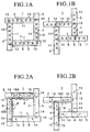
- Reference numeral 1 generally denotes a rectangular support framework for supporting a flat panel display 7 as represented by a liquid crystal panel which is an object to be tested.
- the rectangular support framework 1 is comprised of an upper cross frame plate 2 which is capable of moving vertically alone with respect to a right vertical frame plate 5 and which is capable of moving vertically in association with vertical movement of a left vertical frame plate 4, a lower cross frame plate 3 which is capable of moving vertically alone with respect to the left vertical frame plate 4 and which is capable of moving vertically in association with vertical movement of the right vertical frame plate 5, the left vertical frame plate 4 which is capable of moving laterally alone with respect to the upper cross frame plate 2 and which is capable of moving laterally in association with lateral movement of the lower cross frame plate 3, and the right vertical frame plate 5 which is capable of moving laterally alone with respect to the lower cross frame plate 3 and which is capable of moving laterally in association with lateral movement of the upper cross frame plate 2.
- the vertical movement and lateral movement of the upper and lower cross frame plates 2, 3 and left and right vertical frame plates 4, 5 enlarge or reduce a window 6 which is defined by the upper and lower cross frame plates 2, 3 and left and right vertical frame plates 4, 5.
- the flat panel display 7 is supported on the upper and lower cross frame plates 2, 3 and left and right vertical frame plates 4, 5 which are faced with the enlarged or reduced window 6.
- the upper cross frame plate 2 and the right vertical frame plate 5 are connected such that the upper cross frame plate 2 is capable of moving vertically alone and the upper cross frame plate 2 and right vertical frame plate 5 are capable of moving laterally in association with each other.
- the left vertical frame plate 4 and the upper cross frame plate 2 are connected such that the left vertical frame plate 4 is capable of moving laterally alone and the left vertical frame plate 4 and upper cross frame plate 2 are capable of moving vertically in association with each other.
- the lower cross frame plate 3 and the left vertical frame plate 4 are connected such that the lower cross frame plate 3 is capable of moving vertically alone and the lower cross frame plate 3 and left vertical frame plate 4 are capable of moving laterally in association with each other.
- the right vertical frame plate 5 and the lower cross frame plate 3 are connected such that the right vertical frame plate 5 is capable of moving laterally alone and the right vertical frame plate 5 and lower cross frame plate 3 are capable of moving vertically in association with each other.
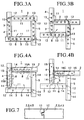
- the above connecting mechanism is shown, for example, in Fig. 7. As shown in Fig. 7, one end of the upper cross frame plate 2 is abutted with an inner surface of the right vertical frame plate 5. Similarly, one end of the left vertical frame plate 4 is abutted with an inner surface of the upper cross frame plate 2. One end of the lower cross frame plate 3 is abutted with an inner surface of the left vertical frame plate 4. One end of the right vertical frame plate 5 is abutted with an inner surface of the lower cross frame plate 3. And the above connecting mechanism is provided at each abutment portion.
- a guide groove 11 is formed in and along an inner surface of each of the upper and lower cross frame plates 2, 3 and left and right vertical frame plates 4, 5 in such a manner as to open at the inner surface.
- that end of each of the frame plates 2, 3, 4, 5 which is abutted with this inner surface is formed with a tab 12 which is key connected to the guide groove 11.
- the tab 12 is slidingly engaged (key connection) in the guide groove 11.
- the upper cross frame plate 2 is capable of moving vertically alone with respect to the right vertical frame plate 5 and it is capable of moving laterally together with the right vertical frame plate 5.
- the left vertical frame plate 4 is capable of moving laterally alone with respect to the upper cross frame plate 2 and it is capable of moving vertically together with the upper lateral frame plate 5.
- the lower cross frame plate 3 is capable of moving vertically alone with respect to the left vertical frame plate 4 and it is capable of moving laterally together with the left vertical frame plate 4.
- the right vertical frame plate 5 is capable of moving laterally alone with respect to the lower lateral frame plate 3 and it is capable of moving vertically together with the lower cross frame plate 3.
- the window 6 is enlarged and reduced.
- Each of the frame plates 2, 3, 4, 5 has suction holes 13 which are arranged on an outer surface thereof generally over the entire length. Those suction holes 13 are connected to a suction device. By means of those suction holes 13, a peripheral edge portion of the flat panel display 7 is suckingly supported on those outer surfaces of the upper and lower cross frame plates 2, 3 and those outer surfaces of the left and right vertical frame plates 4, 5 which are faced with the enlarged or reduced window 6.
- each probe block 8 has a plurality of probes 9 whose distal ends are pressure contacted with the outer surfaces of the electrode pads 10.
- Either of the support framework 1 of the flat panel display 7 and the support framework 1 of the testing probe block 7 is fabricated of a rectangular framework.
- the front rectangular framework 1 on which the testing probe block 8 is supported is disposed on a front surface side of the rear rectangular framework 1 on which the flat panel display 7 as represented by a liquid crystal panel is supported.
- the rear rectangular framework 1 is reciprocally movably disposed on the front rectangular framework 1 such that when the rear rectangular framework 1 advances, the testing probes 9 of the testing probe blocks 8 are pressure contacted with the electrode pads 10 which are arranged on the peripheral edge portion of the flat panel display 7 and when the rear rectangular framework 1 retracts, the displacement of the flat panel display 7 is performed.
- the window 6 of the front rectangular framework 1 is enlarged and the replacement of the flat panel display 7 is performed onto the rear rectangular framework 1 from front of the front rectangular framework 1 through the enlarged window 6.
- the rear rectangular framework 1 it is not necessary for the rear rectangular framework 1 to be disposed reciprocally movably.
- Reference numeral 1 generally denotes a rectangular support framework for supporting a testing probe block 8.
- the rectangular support framework 1 is comprised of an upper cross frame plate 2 which is capable of moving vertically alone with respect to a right vertical frame plate 5 and which is capable of moving vertically in association with vertical movement of a left vertical frame plate 4, a lower cross frame plate 3 which is capable of moving vertically alone with respect to the left vertical frame plate 4 and which is capable of moving vertically in association with vertical movement of the right vertical frame plate 5, the left vertical frame plate 4 which is capable of moving laterally alone with respect to the upper cross frame plate 2 and which is capable of moving laterally in association with lateral movement of the lower cross frame plate 3, and the right vertical frame plate 5 which is capable of moving laterally alone with respect to the lower cross frame plate 3 and which is capable of moving laterally in association with lateral movement of the upper cross frame plate 2.
- the vertical movement and lateral movement of the upper and lower cross frame plates 2, 3 and left and right vertical frame plates 4, 5 enlarge or reduce a window 6 which is defined by the upper and lower cross frame plates 2, 3 and left and right vertical frame plates 4, 5.
- the probe block 8 is supported on the upper and lower cross frame plates 2, 3 and left and right vertical frame plates 4, 5 which are faced with the enlarged or reduced window 6.
- each probe block 8 has a plurality of probes 9 whose distal ends are pressure contacted with the outer surfaces of the electrode pads 10.
- the upper cross frame plate 2 and the right vertical frame plate 5 are connected such that the upper cross frame plate 2 is capable of moving vertically alone and the upper cross frame plate 2 and right vertical frame plate 5 are capable of moving laterally in association with each other.
- the left vertical frame plate 4 and the upper cross frame plate 2 are connected such that the left vertical frame plate 4 is capable of moving laterally alone and the left vertical frame plate 4 and upper cross frame plate 2 are capable of moving vertically in association with each other.
- the lower cross frame plate 3 and the left vertical frame plate 4 are connected such that the lower cross frame plate 3 is capable of moving vertically alone and the lower cross frame plate 3 and left vertical frame plate 4 are capable of moving laterally in association with each other.
- the right vertical frame plate 5 and the lower cross frame plate 3 are connected such that the right vertical frame plate 5 is capable of moving laterally alone and the right vertical frame plate 5 and lower cross frame plate 3 are capable of moving vertically in association with each other.
- the above connecting mechanism is shown, for example, in Fig. 7. As shown in Fig. 7, one end of the upper cross frame plate 2 is abutted with an inner surface of the right vertical frame plate 5. Similarly, one end of the left vertical frame plate 4 is abutted with an inner surface of the upper cross frame plate 2. One end of the lower cross frame plate 3 is abutted with an inner surface of the left vertical frame plate 4. One end of the right vertical frame plate 5 is abutted with an inner surface of the lower cross frame plate 3. And the above connecting mechanism is provided at each abutment portion.
- a guide groove 11 is formed in and along an inner surface of each of the upper and lower cross frame plates 2, 3 and left and right vertical frame plates 4, 5 in such a manner as to open at the inner surface.
- that end of each of the frame plates 2, 3, 4, 5 which is abutted with this inner surface is formed with a tab 12 which is key connected to the guide groove 11.
- the tab 12 is slidingly engaged (key connection) in the guide groove 11.
- the upper cross frame plate 2 is capable of moving vertically alone with respect to the right vertical frame plate 5 and it is capable of moving laterally together with the right vertical frame plate 5.
- the left vertical frame plate 4 is capable of moving laterally alone with respect to the upper cross frame plate 2 and it is capable of moving vertically together with the upper cross frame plate 2.
- the lower cross frame plate 3 is capable of moving vertically alone with respect to the left vertical frame plate 4 and it is capable of moving laterally together with the left vertical frame plate 4.
- the right vertical frame plate 5 is capable of moving laterally alone with respect to the lower lateral frame plate 3 and it is capable of moving vertically together with the lower cross frame plate 3.
- the window 6 is enlarged and reduced.
- Each of the frame plates 2, 3, 4, 5 is equal in length. Each of those frame plates 2, 3, 4, 5 having the equal length is provided at opposite ends of an outer surface thereof with equally spacedly arranged positioning pins or holes 14.
- probe units 16A, 16B, 16C are prepared, which are provided with a plurality of probe blocks 8 removably attached to bases 15 having an equal length and serving as holders of the probe blocks 8 at locations corresponding to the sides of the enlarged or reduced window 6.
- probe units 16A, 16B, 16C are properly selected in accordance with the enlarged or reduced window 6 and inserted in the positioning pins or holes 14 of the frame plates 2, 3, 4, 5 so that the units 16A, 16B, 16C are integrally removably attached thereto.
- the probe blocks 8 are supportingly attached to the frame plates 2, 3, 4, 5 through the bases which serve as holders.
- either of the support framework 1 of the flat panel display 7 and the support framework 1 of the testing probe block 7 is fabricated of a rectangular framework.
- the front rectangular framework 1 on which the testing probe block 8 is supported is disposed on a front surface side of the rear rectangular framework 1 on which the flat panel display 7 as represented by a liquid crystal panel is supported.
- the rear rectangular framework 1 is reciprocally movably disposed on the front rectangular framework 1 such that when the rear rectangular framework 1 advances, the testing probes 9 of the testing probe blocks 8 are pressure contacted with the electrode pads 10 which are arranged on the peripheral edge portion of the flat panel display 7 and when the rear rectangular framework 1 retracts, the displacement of the flat panel display 7 is performed.
- the window 6 of the front rectangular framework 1 is enlarged and the replacement of the flat panel display 7 is performed onto the rear rectangular framework 1 from front of the front rectangular framework 1 through the enlarged window 6.
- the rear rectangular framework 1 it is not necessary for the rear rectangular framework 1 to be disposed reciprocally movably.
- Reference numeral 1 generally denotes a rectangular support framework for supporting a flat panel display 7 as represented by a liquid crystal panel which is an object to be tested.
- the rectangular support framework 1 is comprised of an upper cross frame plate 2 which is capable of moving vertically alone with respect to a left vertical frame plate 4 and which is capable of moving vertically in association with vertical movement of a right vertical frame plate 5, a lower cross frame plate 3 which is capable of moving vertically alone with respect to the right vertical frame plate 5 and which is capable of moving vertically in association with vertical movement of the left vertical frame plate 4, the left vertical frame plate 4 which is capable of moving laterally alone with respect to the lower cross frame plate 3 and which is capable of moving laterally in association with lateral movement of the upper cross frame plate 2, and the right vertical frame plate 5 which is capable of moving laterally alone with respect to the upper cross frame plate 2 and which is capable of moving laterally in association with lateral movement of the lower cross frame plate 3.
- the vertical movement and lateral movement of the upper and lower cross frame plates 2, 3 and left and right vertical frame plates 4, 5 enlarge or reduce a window 6 which is defined by the upper and lower cross frame plates 2, 3 and left and right vertical frame plates 4, 5.
- the flat panel display 7 is supported on the upper and lower cross frame plates 2, 3 and left and right vertical frame plates 4, 5 which are faced with the enlarged or reduced window 6.
- the upper cross frame plate 2 and the left vertical frame plate 4 are connected such that the upper cross frame plate 2 is capable of moving vertically alone and the upper cross frame plate 2 and left vertical frame plate 4 are capable of moving laterally in association with each other.
- the right vertical frame plate 5 and the upper cross frame plate 2 are connected such that the right vertical frame plate 5 is capable of moving laterally alone and the right vertical frame plate 5 and upper cross frame plate 2 are capable of moving vertically in association with each other.
- the lower cross frame plate 3 and the right vertical frame plate 5 are connected such that the lower cross frame plate 3 is capable of moving vertically alone and the lower cross frame plate 3 and right vertical frame plate 5 are capable of moving laterally in association with each other.
- the left vertical frame plate 4 and the lower cross frame plate 3 are connected such that the left vertical frame plate 4 is capable of moving laterally alone and the left vertical frame plate 4 and lower cross frame plate 3 are capable of moving vertically in association with each other.
- the above connecting mechanism is shown, for example, in Fig. 7. As shown in Fig. 7, one end of the upper cross frame plate 2 is abutted with an inner surface of the right vertical frame plate 5. Similarly, one end of the left vertical frame plate 4 is abutted with an inner surface of the upper cross frame plate 2. One end of the lower cross frame plate 3 is abutted with an inner surface of the left vertical frame plate 4. One end of the right vertical frame plate 5 is abutted with an inner surface of the lower cross frame plate 3. And the above connecting mechanism is provided at each abutment portion.
- a guide groove 11 is formed in and along an inner surface of each of the upper and lower cross frame plates 2, 3 and left and right vertical frame plates 4, 5 in such a manner as to open at the inner surface.
- that end of each of the frame plates 2, 3, 4, 5 which is abutted with this inner surface is formed with a tab 12 which is key connected to the guide groove 11.
- the tab 12 is slidingly engaged (key connection) in the guide groove 11.
- the upper cross frame plate 2 is capable of moving vertically alone with respect to the right vertical frame plate 5 and it is capable of moving laterally together with the right vertical frame plate 5.
- the left vertical frame plate 4 is capable of moving laterally alone with respect to the upper cross frame plate 2 and it is capable of moving vertically together with the upper lateral frame plate 5.
- the lower cross frame plate 3 is capable of moving vertically alone with respect to the left vertical frame plate 4 and it is capable of moving laterally together with the left vertical frame plate 4.
- the right vertical frame plate 5 is capable of moving laterally alone with respect to the lower lateral frame plate 3 and it is capable of moving vertically together with the lower cross frame plate 3.
- the window 6 is enlarged and reduced.
- Each of the frame plates 2, 3, 4, 5 has suction holes 13 which are arranged on an outer surface thereof generally over the entire length. Those suction holes 13 are connected to a suction device. By means of those suction holes 13, a peripheral edge portion of the flat panel display 7 is suckingly supported on those outer surfaces of the upper and lower cross frame plates 2, 3 and those outer surfaces of the left and right vertical frame plates 4, 5 which are faced with the enlarged or reduced window 6.
- each probe block 8 has a plurality of probes 9 whose distal ends are pressure contacted with the outer surfaces of the electrode pads 10.
- Either of the support framework 1 of the flat panel display 7 and the support framework 1 of the testing probe block 7 is fabricated of a rectangular framework.
- the front rectangular framework 1 on which the testing probe block 8 is supported is disposed on a front surface side of the rear rectangular framework 1 on which the flat panel display 7 as represented by a liquid crystal panel is supported.
- the rear rectangular framework 1 is reciprocally movably disposed on the front rectangular framework 1 such that when the rear rectangular framework 1 advances, the testing probes 9 of the testing probe blocks 8 are pressure contacted with the electrode pads 10 which are arranged on the peripheral edge portion of the flat panel display 7 and when the rear rectangular framework 1 retracts, the displacement of the flat panel display 7 is performed.
- the window 6 of the front rectangular framework 1 is enlarged and the replacement of the flat panel display 7 is performed onto the rear rectangular framework 1 from front of the front rectangular framework 1 through the enlarged window 6.
- the rear rectangular framework 1 it is not necessary for the rear rectangular framework 1 to be disposed reciprocally movably.
- Reference numeral 1 generally denotes a rectangular support framework for supporting a testing probe block 8.
- the rectangular support framework 1 is comprised of an upper cross frame plate 2 which is capable of moving vertically alone with respect to a left vertical frame plate 4 and which is capable of moving vertically in association with vertical movement of a right vertical frame plate 5, a lower cross frame plate 3 which is capable of moving vertically alone with respect to the right vertical frame plate 5 and which is capable of moving vertically in association with vertical movement of the left vertical frame plate 4, the left vertical frame plate 4 which is capable of moving laterally alone with respect to the lower cross frame plate 3 and which is capable of moving laterally in association with lateral movement of the upper cross frame plate 2, and the right vertical frame plate 5 which is capable of moving laterally alone with respect to the upper cross frame plate 2 and which is capable of moving laterally in association with lateral movement of the lower cross frame plate 3.
- the vertical movement and lateral movement of the upper and lower cross frame plates 2, 3 and left and right vertical frame plates 4, 5 enlarge or reduce a window 6 which is defined by the upper and lower cross frame plates 2, 3 and left and right vertical frame plates 4, 5.
- each probe block 8 has a plurality of probes 9 whose distal ends are pressure contacted with the outer surfaces of the electrode pads 10.
- the upper cross frame plate 2 and the left vertical frame plate 4 are connected such that the upper cross frame plate 2 is capable of moving vertically alone and the upper cross frame plate 2 and the left vertical frame plate 4 are capable of moving laterally in association with each other.
- the right vertical frame plate 5 and the upper cross frame plate 2 are connected such that the right vertical frame plate 5 is capable of moving laterally alone and the right vertical frame plate 5 and upper cross frame plate 2 are capable of moving vertically in association with each other.
- the lower cross frame plate 3 and the right vertical frame plate 5 are connected such that the lower cross frame plate 3 is capable of moving vertically alone and the lower cross frame plate 3 and right vertical frame plate 5 are capable of moving laterally in association with each other.
- the left vertical frame plate 4 and the lower cross frame plate 3 are connected such that the left vertical frame plate 4 is capable of moving laterally alone and the left vertical frame plate 4 and lower cross frame plate 3 are capable of moving vertically in association with each other.
- the above connecting mechanism is shown, for example, in Fig. 7. As shown in Fig. 7, one end of the upper cross frame plate 2 is abutted with an inner surface of the right vertical frame plate 5. Similarly, one end of the left vertical frame plate 4 is abutted with an inner surface of the upper cross frame plate 2. One end of the lower cross frame plate 3 is abutted with an inner surface of the left vertical frame plate 4. One end of the right vertical frame plate 5 is abutted with an inner surface of the lower cross frame plate 3. And the above connecting mechanism is provided at each abutment portion.
- a guide groove 11 is formed in and along an inner surface of each of the upper and lower cross frame plates 2, 3 and left and right vertical frame plates 4, 5 in such a manner as to open at the inner surface.
- that end of each of the frame plates 2, 3, 4, 5 which is abutted with this inner surface is formed with a tab 12 which is key connected to the guide groove 11.
- the tab 12 is slidingly engaged (key connection) in the guide groove 11.
- the upper cross frame plate 2 is capable of moving vertically alone with respect to the right vertical frame plate 5 and it is capable of moving laterally together with the right vertical frame plate 5.
- the left vertical frame plate 4 is capable of moving laterally alone with respect to the upper cross frame plate 2 and it is capable of moving vertically together with the upper cross frame plate 2.
- the lower cross frame plate 3 is capable of moving vertically alone with respect to the left vertical frame plate 4 and it is capable of moving laterally together with the left vertical frame plate 4.
- the right vertical frame plate 5 is capable of moving laterally alone with respect to the lower lateral frame plate 3 and it is capable of moving vertically together with the lower cross frame plate 3.
- the window 6 is enlarged and reduced.
- Each of the frame plates 2, 3, 4, 5 is equal in length. Each of those frame plates 2, 3, 4, 5 having the equal length is provided at opposite ends of an outer surface thereof with equally spacedly arranged positioning pins or holes 14.
- probe units 16A, 16B, 16C are prepared, which are provided with a plurality of probe blocks 8 removably attached to bases 15 having an equal length and serving as holders of the probe blocks 8 at locations corresponding to the sides of the enlarged or reduced window 6.
- probe units 16A, 16B, 16C are properly selected in accordance with the enlarged or reduced window 6 and inserted in the positioning pins or holes 14 of the frame plates 2, 3, 4, 5 so that the units 16A, 16B, 16C are integrally removably attached thereto.
- the probe blocks 8 are supportingly attached to the frame plates 2, 3, 4, 5 through the bases which serve as holders.
- either of the support framework 1 of the flat panel display 7 and the support framework 1 of the testing probe block 7 is fabricated of a rectangular framework.
- the front rectangular framework 1 on which the testing probe block 8 is supported is disposed on a front surface side of the rear rectangular framework 1 on which the flat panel display 7 as represented by a liquid crystal panel is supported.
- the rear rectangular framework 1 is reciprocally movably disposed on the front rectangular framework 1 such that when the rear rectangular framework 1 advances, the testing probes 9 of the testing probe blocks 8 are pressure contacted with the electrode pads 10 which are arranged on the peripheral edge portion of the flat panel display 7 and when the rear rectangular framework 1 retracts, the displacement of the flat panel display 7 is performed.
- the window 6 of the front rectangular framework 1 is enlarged and the replacement of the flat panel display 7 is performed onto the rear rectangular framework 1 from front of the front rectangular framework 1 through the enlarged window 6.
- the rear rectangular framework 1 it is not necessary for the rear rectangular framework 1 to be disposed reciprocally movably.
- the rectangular support framework 1 fabricated of the frame plates 2, 3, 4, 5 on which the flat panel display 7 is supported is disposed on a rear surface side of the rectangular support framework 1 fabricated of the frame plates 2, 3, 4, 5 on which the testing probe block 8 is supported.
- An illumination means is disposed at the rear part of the window 6 of the rear surface side rectangular support framework 1 on which the flat panel display 7 is supported.
- the flat panel display 7 is illuminated by the illumination means through the window 6.
- the present invention is applicable to either the rectangular support framework 1 on which the flat panel display 7 is supported or the rectangular support framework 1 on which the testing probe block 8 is supported.
- support frameworks having sizes corresponding to a wide variety of flat panel displays can easily be made by means of vertical or lateral movement of the upper and lower cross frame plates and the left and right vertical frame plates.
- testing probe support frameworks having sizes corresponding to a wide variety of flat panel displays can easily be made. This makes it possible to apply a test device to various kinds of flat panel displays which have different sizes.
- the present invention is economically efficient and it can enhance efficiency of the testing operation.
Landscapes
- Engineering & Computer Science (AREA)
- Physics & Mathematics (AREA)
- Computer Hardware Design (AREA)
- General Physics & Mathematics (AREA)
- Theoretical Computer Science (AREA)
- Measuring Leads Or Probes (AREA)
- Tests Of Electronic Circuits (AREA)
- Testing Of Optical Devices Or Fibers (AREA)
- Devices For Indicating Variable Information By Combining Individual Elements (AREA)
- Testing Electric Properties And Detecting Electric Faults (AREA)
- Automatic Cycles, And Cycles In General (AREA)
Abstract
Description
Claims (4)
- A rectangular support framework of a flat panel display as an object to be tested or a testing probe block, said rectangular support framework comprising an upper cross frame plate which is capable of moving vertically alone with respect to a right vertical frame plate and which is capable of moving vertically in association with vertical movement of a left vertical frame plate, a lower cross frame plate which is capable of moving vertically alone with respect to said left vertical frame plate and which is capable of moving vertically in association with vertical movement of said right vertical frame plate, said left vertical frame plate which is capable of moving laterally alone with respect to said upper cross frame plate and which is capable of moving laterally in association with lateral movement of said lower cross frame plate, and said right vertical frame plate which is capable of moving laterally alone with respect to said lower cross frame plate and which is capable of moving laterally in association with lateral movement of said upper cross frame plate, the vertical movement and lateral movement of said upper and lower cross frame plates and left and right vertical frame plates enlarging or reducing a window which is defined by said upper and lower cross frame plates and left and right vertical frame plates, said flat panel display or said probe block which is subjected to pressure contact with electrode pads arranged on a peripheral edge portion of said flat panel display being supported on said upper and lower cross frame plates and left and right vertical frame plates which are faced with said enlarged or reduced window.
- A rectangular support framework of a flat panel display as an object to be tested or a testing probe block according to claim 1, wherein said upper cross frame plate and said right vertical frame plate are connected such that said upper cross frame plate is capable of moving vertically alone and said upper cross frame plate and right vertical frame plate are capable of moving laterally in association with each other, said left vertical frame plate and said upper cross frame plate are connected such that said left vertical frame plate is capable of moving laterally alone and said left vertical frame plate and upper cross frame plate are capable of moving vertically in association with each other, said lower cross frame plate and said left vertical frame plate are connected such that said lower cross frame plate is capable of moving vertically alone and said lower cross frame plate and left vertical frame plate are capable of moving laterally in association with each other, and said right vertical frame plate and said lower cross frame plate are connected such that said right vertical frame plate is capable of moving laterally alone and said right vertical frame plate and lower cross frame plate are capable of moving vertically in association with each other.
- A rectangular support framework of a flat panel display as an object to be tested or a testing probe block, said rectangular support framework comprising an upper cross frame plate which is capable of moving vertically alone with respect to a left vertical frame plate and which is capable of moving vertically in association with vertical movement of a right vertical frame plate, a lower cross frame plate which is capable of moving vertically alone with respect to said right vertical frame plate and which is capable of moving vertically in association with vertical movement of said left vertical frame plate, said left vertical frame plate which is capable of moving laterally alone with respect to said lower cross frame plate and which is capable of moving laterally in association with lateral movement of said upper cross frame plate, and said right vertical frame plate which is capable of moving laterally alone with respect to said upper cross frame plate and which is capable of moving laterally in association with lateral movement of said lower cross frame plate, the vertical movement and lateral movement of said upper and lower cross frame plates and left and right vertical frame plates enlarging or reducing a window which is defined by said upper and lower cross frame plates and left and right vertical frame plates, said flat panel display or said probe block which is subjected to pressure contact with electrode pads arranged on a peripheral edge portion of said flat panel display being supported on said upper and lower cross frame plates and left and right vertical frame plates which are faced with said enlarged or reduced window.
- A rectangular support framework of a flat panel display as an object to be tested or a testing probe block according to claim 4, wherein said upper cross frame plate and said left vertical frame plate are connected such that said upper cross frame plate is capable of moving vertically alone and said upper cross frame plate and left vertical frame plate are capable of moving laterally in association with each other, said right vertical frame plate and said upper cross frame plate are connected such that said right vertical frame plate is capable of moving laterally alone and said right vertical frame plate and upper cross frame plate are capable of moving vertically in association with each other, said lower cross frame plate and said right vertical frame plate are connected such that said lower cross frame plate is capable of moving vertically alone and said lower cross frame plate and right vertical frame plate are capable of moving laterally in association with each other, and said left vertical frame plate and said lower cross frame plate are connected such that said left vertical frame plate is capable of moving laterally alone and said left vertical frame plate and lower cross frame plate are capable of moving vertically in association with each other.
Applications Claiming Priority (2)
| Application Number | Priority Date | Filing Date | Title |
|---|---|---|---|
| JP24510499A JP3350899B2 (en) | 1999-08-31 | 1999-08-31 | Probe block support frame |
| JP24510499 | 1999-08-31 |
Publications (2)
| Publication Number | Publication Date |
|---|---|
| EP1081497A2 true EP1081497A2 (en) | 2001-03-07 |
| EP1081497A3 EP1081497A3 (en) | 2004-05-12 |
Family
ID=17128684
Family Applications (1)
| Application Number | Title | Priority Date | Filing Date |
|---|---|---|---|
| EP00303804A Withdrawn EP1081497A3 (en) | 1999-08-31 | 2000-05-05 | Flat panel display support framework |
Country Status (7)
| Country | Link |
|---|---|
| US (1) | US6450469B1 (en) |
| EP (1) | EP1081497A3 (en) |
| JP (1) | JP3350899B2 (en) |
| KR (1) | KR20010020825A (en) |
| CN (1) | CN1145066C (en) |
| IT (1) | IT1320603B1 (en) |
| TW (1) | TW459140B (en) |
Cited By (1)
| Publication number | Priority date | Publication date | Assignee | Title |
|---|---|---|---|---|
| CN1309248C (en) * | 2002-08-02 | 2007-04-04 | Nec液晶技术株式会社 | Display device and panel supporting frame and manufacture thereof |
Families Citing this family (41)
| Publication number | Priority date | Publication date | Assignee | Title |
|---|---|---|---|---|
| US7073768B2 (en) * | 2002-07-12 | 2006-07-11 | John Piscovich | Device and method for setting a frame |
| JP3457938B2 (en) * | 2000-10-16 | 2003-10-20 | 株式会社双晶テック | Method of replacing display board or circuit board in display board or circuit board inspection apparatus |
| TW509329U (en) * | 2001-04-19 | 2002-11-01 | Hannstar Display Corp | Electrified rack |
| KR20020091691A (en) * | 2001-05-31 | 2002-12-06 | 주식회사 현대 디스플레이 테크놀로지 | Liquid crystal display test frame |
| US20040051693A1 (en) * | 2002-09-12 | 2004-03-18 | Ming-Jian Chen | Electronic screen having display panel displayed in changeable length-width ratio |
| US7012583B2 (en) * | 2003-02-07 | 2006-03-14 | Shimadzu Corporation | Apparatus and method for testing pixels of flat panel display |
| US7355418B2 (en) | 2004-02-12 | 2008-04-08 | Applied Materials, Inc. | Configurable prober for TFT LCD array test |
| US7319335B2 (en) | 2004-02-12 | 2008-01-15 | Applied Materials, Inc. | Configurable prober for TFT LCD array testing |
| US6833717B1 (en) | 2004-02-12 | 2004-12-21 | Applied Materials, Inc. | Electron beam test system with integrated substrate transfer module |
| JP4790997B2 (en) * | 2004-03-26 | 2011-10-12 | 株式会社日本マイクロニクス | Probe device |
| JP4570930B2 (en) * | 2004-10-22 | 2010-10-27 | 株式会社日本マイクロニクス | Electrical connection device used in panel inspection equipment |
| KR100776177B1 (en) * | 2004-12-17 | 2007-11-16 | 주식회사 디이엔티 | Work table for flat panel display inspection device |
| US7535238B2 (en) | 2005-04-29 | 2009-05-19 | Applied Materials, Inc. | In-line electron beam test system |
| US20070018062A1 (en) * | 2005-07-20 | 2007-01-25 | Theodor Calinescu | Universal wall mount bracket for displays |
| KR100748072B1 (en) * | 2005-08-01 | 2007-08-09 | 가부시키가이샤 니혼 마이크로닉스 | Electrical inspection device of display panel |
| JP4916712B2 (en) * | 2005-12-16 | 2012-04-18 | 株式会社日本マイクロニクス | Display panel inspection device |
| US7569818B2 (en) | 2006-03-14 | 2009-08-04 | Applied Materials, Inc. | Method to reduce cross talk in a multi column e-beam test system |
| US7786742B2 (en) | 2006-05-31 | 2010-08-31 | Applied Materials, Inc. | Prober for electronic device testing on large area substrates |
| US7602199B2 (en) | 2006-05-31 | 2009-10-13 | Applied Materials, Inc. | Mini-prober for TFT-LCD testing |
| JP4917852B2 (en) * | 2006-08-21 | 2012-04-18 | 株式会社日本マイクロニクス | Panel support mechanism and inspection device |
| GB0711626D0 (en) * | 2007-06-18 | 2007-07-25 | Barco Nv | Support for direct light displays |
| KR100911236B1 (en) * | 2007-08-22 | 2009-08-06 | 주식회사 플라켐 | Block type LED lighting |
| JP4845897B2 (en) * | 2008-01-15 | 2011-12-28 | 株式会社東芝 | Sample stage |
| KR100920383B1 (en) * | 2009-01-29 | 2009-10-07 | 주식회사 에이디피엔지니어링 | Flat panel display device manufacturing device |
| CN102884567B (en) * | 2010-06-17 | 2015-01-28 | 夏普株式会社 | Lighting inspection device |
| KR101102556B1 (en) | 2010-06-30 | 2012-01-03 | (주)이노셈코리아 | Removable LED module with customized power consumption and multi-formation |
| CN102455528B (en) * | 2010-10-27 | 2015-01-07 | 纬创资通股份有限公司 | Flat-panel display combined with upper and lower cover appearance parts |
| TWI435294B (en) * | 2010-12-03 | 2014-04-21 | Wistron Corp | Flat panel display |
| US20130128513A1 (en) * | 2011-11-18 | 2013-05-23 | Shenzhen China Star Optoelectronics Technology Co., Ltd. | Mold for Back Frame and Bracing Piece, Method for Manufacturing Back Frame, and Backlight System |
| CN102830517B (en) * | 2012-08-28 | 2015-02-18 | 深圳市华星光电技术有限公司 | Back frame and liquid crystal display device |
| US8850992B1 (en) * | 2013-05-22 | 2014-10-07 | Itoro Akpaffiong | Portable articulated support frame for supporting objects on a user's lap |
| KR102242643B1 (en) * | 2014-10-30 | 2021-04-22 | 주성엔지니어링(주) | Organic Light Emitting Device |
| CN104360510B (en) * | 2014-11-24 | 2018-02-16 | 合肥鑫晟光电科技有限公司 | A kind of detection probe block and its detection means |
| KR102608599B1 (en) | 2018-08-16 | 2023-12-01 | 삼성디스플레이 주식회사 | Device and method for testing pressure sensor and display device using the same |
| JP7202483B2 (en) * | 2019-04-17 | 2023-01-11 | メガセン・カンパニー・リミテッド | Mother glass panel transfer device, display panel inspection device and display panel inspection equipment |
| KR102081609B1 (en) * | 2019-04-17 | 2020-02-26 | 우리마이크론(주) | Mother panel transferring apparatus, display panel inspection apparatus and display panel inspection equipment |
| JP7250182B2 (en) * | 2019-07-01 | 2023-03-31 | メガセン・カンパニー・リミテッド | Probe block assembly for display panel inspection, its control method and display panel inspection apparatus |
| KR102097456B1 (en) * | 2019-07-01 | 2020-04-07 | 우리마이크론(주) | Probe block assembly for inspecting display panel, control method thereof and display panel inspection device |
| KR102097455B1 (en) * | 2019-07-01 | 2020-04-07 | 우리마이크론(주) | Probe block assembly for inspecting display panel, control method thereof and display panel inspection device |
| KR102154758B1 (en) * | 2020-03-30 | 2020-09-10 | 우리마이크론(주) | Probe block assembly for inspecting display panel, control method thereof and display panel inspection device |
| KR102154760B1 (en) * | 2020-03-30 | 2020-09-10 | 우리마이크론(주) | Probe block assembly for inspecting display panel, control method thereof and display panel inspection device |
Family Cites Families (7)
| Publication number | Priority date | Publication date | Assignee | Title |
|---|---|---|---|---|
| US3612508A (en) * | 1970-04-08 | 1971-10-12 | Gen Motors Corp | Heater core fixture for face soldering |
| JPS5391376A (en) * | 1977-01-24 | 1978-08-11 | Hirohide Yano | Device for inspecting printed board |
| US5003254A (en) * | 1989-11-02 | 1991-03-26 | Huntron, Inc. | Multi-axis universal circuit board test fixture |
| JPH0996802A (en) * | 1995-10-03 | 1997-04-08 | Sharp Corp | LCD panel manufacturing jig |
| JP3592831B2 (en) * | 1996-02-26 | 2004-11-24 | 株式会社日本マイクロニクス | Probe unit and adjustment method thereof |
| US5954106A (en) * | 1998-05-18 | 1999-09-21 | Huang; Jin Lai | Work bench having an adjustable guide |
| US6150833A (en) * | 1999-02-03 | 2000-11-21 | Industrial Technology Research Institute | LCD panel power-up test fixture and method of using |
-
1999
- 1999-08-31 JP JP24510499A patent/JP3350899B2/en not_active Expired - Lifetime
-
2000
- 2000-04-26 TW TW089107918A patent/TW459140B/en not_active IP Right Cessation
- 2000-05-05 US US09/566,010 patent/US6450469B1/en not_active Expired - Fee Related
- 2000-05-05 EP EP00303804A patent/EP1081497A3/en not_active Withdrawn
- 2000-05-10 KR KR1020000024824A patent/KR20010020825A/en not_active Withdrawn
- 2000-06-06 CN CNB001179705A patent/CN1145066C/en not_active Expired - Lifetime
- 2000-08-25 IT IT2000TO000817A patent/IT1320603B1/en active
Cited By (1)
| Publication number | Priority date | Publication date | Assignee | Title |
|---|---|---|---|---|
| CN1309248C (en) * | 2002-08-02 | 2007-04-04 | Nec液晶技术株式会社 | Display device and panel supporting frame and manufacture thereof |
Also Published As
| Publication number | Publication date |
|---|---|
| KR20010020825A (en) | 2001-03-15 |
| CN1145066C (en) | 2004-04-07 |
| EP1081497A3 (en) | 2004-05-12 |
| JP3350899B2 (en) | 2002-11-25 |
| US6450469B1 (en) | 2002-09-17 |
| JP2001074599A (en) | 2001-03-23 |
| TW459140B (en) | 2001-10-11 |
| ITTO20000817A1 (en) | 2002-02-25 |
| ITTO20000817A0 (en) | 2000-08-25 |
| IT1320603B1 (en) | 2003-12-10 |
| CN1291728A (en) | 2001-04-18 |
Similar Documents
| Publication | Publication Date | Title |
|---|---|---|
| US6450469B1 (en) | Flat panel display or probe block support framework | |
| US4344033A (en) | Vacuum-actuated test fixture for printed circuit boards | |
| TW515907B (en) | Supporting framework for display panel or probe block | |
| EP1666958A3 (en) | Liquid crystal display apparatus | |
| US5087878A (en) | Top-accessible system, and related methods, for simultaneously testing the opposite sides of printed circuit board | |
| JP2000007146A (en) | Glass substrate holding tool | |
| JP3648349B2 (en) | Display panel substrate inspection method and apparatus | |
| CN101813855B (en) | Apparatus for attaching substrates and gap control unit thereof | |
| JPH0738231A (en) | Metal mask for cream solder and mounting method to frame | |
| EP1199571A2 (en) | Apparatus for inspecting display board or circuit board | |
| KR20050025228A (en) | Electrical connection device | |
| JP3816031B2 (en) | Inspection device for flat panel display | |
| JP2000304814A (en) | Apparatus for supporting bearing board | |
| CN218865010U (en) | Visual detection device for middle frame of notebook computer | |
| CN222233198U (en) | A removable sign | |
| CN211826441U (en) | Detection equipment convenient to VGA interface dismouting | |
| CN217638633U (en) | Tool of test lamp pearl fastness | |
| CN218301730U (en) | PCB structure with four corners installation | |
| CN223617561U (en) | High-precision positioning tool for processing display screen | |
| CN222719260U (en) | Medical adhesive glass slide | |
| JP3637150B2 (en) | Display panel substrate inspection method and apparatus | |
| CN213250693U (en) | Uropoiesis surgery inspection is with portable isolating device | |
| JPH0452690Y2 (en) | ||
| KR200411200Y1 (en) | Keypad jig for mobile communication terminal | |
| KR20000012161U (en) | Jig for testing printed circuit board of liquid crystal module |
Legal Events
| Date | Code | Title | Description |
|---|---|---|---|
| PUAI | Public reference made under article 153(3) epc to a published international application that has entered the european phase |
Free format text: ORIGINAL CODE: 0009012 |
|
| AK | Designated contracting states |
Kind code of ref document: A2 Designated state(s): AT BE CH CY DE DK ES FI FR GB GR IE IT LI LU MC NL PT SE |
|
| AX | Request for extension of the european patent |
Free format text: AL;LT;LV;MK;RO;SI |
|
| PUAL | Search report despatched |
Free format text: ORIGINAL CODE: 0009013 |
|
| AK | Designated contracting states |
Kind code of ref document: A3 Designated state(s): AT BE CH CY DE DK ES FI FR GB GR IE IT LI LU MC NL PT SE |
|
| AX | Request for extension of the european patent |
Extension state: AL LT LV MK RO SI |
|
| RIC1 | Information provided on ipc code assigned before grant |
Ipc: 7G 01R 31/28 A |
|
| AKX | Designation fees paid | ||
| REG | Reference to a national code |
Ref country code: DE Ref legal event code: 8566 |
|
| STAA | Information on the status of an ep patent application or granted ep patent |
Free format text: STATUS: THE APPLICATION IS DEEMED TO BE WITHDRAWN |
|
| 18D | Application deemed to be withdrawn |
Effective date: 20041113 |