EP1081487A2 - Nebulizer - Google Patents
Nebulizer Download PDFInfo
- Publication number
- EP1081487A2 EP1081487A2 EP00119308A EP00119308A EP1081487A2 EP 1081487 A2 EP1081487 A2 EP 1081487A2 EP 00119308 A EP00119308 A EP 00119308A EP 00119308 A EP00119308 A EP 00119308A EP 1081487 A2 EP1081487 A2 EP 1081487A2
- Authority
- EP
- European Patent Office
- Prior art keywords
- gas
- nebulizer
- orifice
- liquid
- tube
- Prior art date
- Legal status (The legal status is an assumption and is not a legal conclusion. Google has not performed a legal analysis and makes no representation as to the accuracy of the status listed.)
- Granted
Links
- 239000006199 nebulizer Substances 0.000 title claims abstract description 188
- 239000007921 spray Substances 0.000 claims abstract description 124
- 238000005507 spraying Methods 0.000 claims abstract description 38
- 239000007789 gas Substances 0.000 claims description 229
- 239000007788 liquid Substances 0.000 claims description 117
- 239000000126 substance Substances 0.000 claims description 25
- 239000012488 sample solution Substances 0.000 claims description 23
- 239000000443 aerosol Substances 0.000 claims description 22
- 150000002500 ions Chemical class 0.000 claims description 22
- 239000002904 solvent Substances 0.000 claims description 20
- 238000000926 separation method Methods 0.000 claims description 10
- 238000012545 processing Methods 0.000 claims description 8
- 239000012528 membrane Substances 0.000 claims description 6
- 238000000889 atomisation Methods 0.000 claims description 5
- 238000001816 cooling Methods 0.000 claims description 5
- 230000005855 radiation Effects 0.000 claims description 5
- 230000005284 excitation Effects 0.000 claims description 4
- 238000004401 flow injection analysis Methods 0.000 claims description 4
- 238000010521 absorption reaction Methods 0.000 claims description 3
- 230000008878 coupling Effects 0.000 claims description 2
- 238000010168 coupling process Methods 0.000 claims description 2
- 238000005859 coupling reaction Methods 0.000 claims description 2
- 239000002737 fuel gas Substances 0.000 claims description 2
- 238000007599 discharging Methods 0.000 claims 6
- 239000000523 sample Substances 0.000 description 49
- 238000004458 analytical method Methods 0.000 description 19
- 239000011521 glass Substances 0.000 description 15
- 230000035945 sensitivity Effects 0.000 description 15
- 238000010586 diagram Methods 0.000 description 13
- 238000001095 inductively coupled plasma mass spectrometry Methods 0.000 description 13
- 238000000034 method Methods 0.000 description 13
- 239000000853 adhesive Substances 0.000 description 9
- 230000001070 adhesive effect Effects 0.000 description 9
- 238000004519 manufacturing process Methods 0.000 description 8
- 239000000243 solution Substances 0.000 description 8
- 230000035939 shock Effects 0.000 description 7
- 238000002354 inductively-coupled plasma atomic emission spectroscopy Methods 0.000 description 6
- 238000002347 injection Methods 0.000 description 6
- 239000007924 injection Substances 0.000 description 6
- VYPSYNLAJGMNEJ-UHFFFAOYSA-N silicon dioxide Inorganic materials O=[Si]=O VYPSYNLAJGMNEJ-UHFFFAOYSA-N 0.000 description 6
- 238000001479 atomic absorption spectroscopy Methods 0.000 description 5
- 230000000694 effects Effects 0.000 description 5
- 238000011144 upstream manufacturing Methods 0.000 description 5
- XLYOFNOQVPJJNP-UHFFFAOYSA-N water Substances O XLYOFNOQVPJJNP-UHFFFAOYSA-N 0.000 description 5
- 238000001962 electrophoresis Methods 0.000 description 4
- 238000009616 inductively coupled plasma Methods 0.000 description 4
- 229910010293 ceramic material Inorganic materials 0.000 description 3
- 238000011156 evaluation Methods 0.000 description 3
- 238000002474 experimental method Methods 0.000 description 3
- 230000002572 peristaltic effect Effects 0.000 description 3
- 239000011347 resin Substances 0.000 description 3
- 229920005989 resin Polymers 0.000 description 3
- 238000010206 sensitivity analysis Methods 0.000 description 3
- XKRFYHLGVUSROY-UHFFFAOYSA-N Argon Chemical compound [Ar] XKRFYHLGVUSROY-UHFFFAOYSA-N 0.000 description 2
- 238000001636 atomic emission spectroscopy Methods 0.000 description 2
- 239000007853 buffer solution Substances 0.000 description 2
- 238000005251 capillar electrophoresis Methods 0.000 description 2
- 150000001793 charged compounds Chemical class 0.000 description 2
- 238000001514 detection method Methods 0.000 description 2
- 238000005516 engineering process Methods 0.000 description 2
- CNKHSLKYRMDDNQ-UHFFFAOYSA-N halofenozide Chemical compound C=1C=CC=CC=1C(=O)N(C(C)(C)C)NC(=O)C1=CC=C(Cl)C=C1 CNKHSLKYRMDDNQ-UHFFFAOYSA-N 0.000 description 2
- 238000005040 ion trap Methods 0.000 description 2
- 238000004949 mass spectrometry Methods 0.000 description 2
- 239000000463 material Substances 0.000 description 2
- 238000005259 measurement Methods 0.000 description 2
- 238000012986 modification Methods 0.000 description 2
- 230000004048 modification Effects 0.000 description 2
- 238000001637 plasma atomic emission spectroscopy Methods 0.000 description 2
- 238000004445 quantitative analysis Methods 0.000 description 2
- 239000010453 quartz Substances 0.000 description 2
- 239000010979 ruby Substances 0.000 description 2
- 229910001750 ruby Inorganic materials 0.000 description 2
- 239000000377 silicon dioxide Substances 0.000 description 2
- 238000009834 vaporization Methods 0.000 description 2
- 230000008016 vaporization Effects 0.000 description 2
- 239000002699 waste material Substances 0.000 description 2
- IJGRMHOSHXDMSA-UHFFFAOYSA-N Atomic nitrogen Chemical compound N#N IJGRMHOSHXDMSA-UHFFFAOYSA-N 0.000 description 1
- 229910004835 Na2B4O7 Inorganic materials 0.000 description 1
- 229910018143 SeO3 Inorganic materials 0.000 description 1
- BUGBHKTXTAQXES-UHFFFAOYSA-N Selenium Chemical compound [Se] BUGBHKTXTAQXES-UHFFFAOYSA-N 0.000 description 1
- 238000002835 absorbance Methods 0.000 description 1
- HSFWRNGVRCDJHI-UHFFFAOYSA-N alpha-acetylene Natural products C#C HSFWRNGVRCDJHI-UHFFFAOYSA-N 0.000 description 1
- 239000012491 analyte Substances 0.000 description 1
- 229910052786 argon Inorganic materials 0.000 description 1
- 229910052785 arsenic Inorganic materials 0.000 description 1
- RQNWIZPPADIBDY-UHFFFAOYSA-N arsenic atom Chemical compound [As] RQNWIZPPADIBDY-UHFFFAOYSA-N 0.000 description 1
- 125000001870 arsonato group Chemical group O=[As]([O-])([O-])[*] 0.000 description 1
- 238000000559 atomic spectroscopy Methods 0.000 description 1
- 230000015572 biosynthetic process Effects 0.000 description 1
- 238000004364 calculation method Methods 0.000 description 1
- 239000012159 carrier gas Substances 0.000 description 1
- 239000011248 coating agent Substances 0.000 description 1
- 238000000576 coating method Methods 0.000 description 1
- 239000000110 cooling liquid Substances 0.000 description 1
- 230000010485 coping Effects 0.000 description 1
- 230000007797 corrosion Effects 0.000 description 1
- 238000005260 corrosion Methods 0.000 description 1
- 230000007423 decrease Effects 0.000 description 1
- 230000001419 dependent effect Effects 0.000 description 1
- 230000008021 deposition Effects 0.000 description 1
- 230000000994 depressogenic effect Effects 0.000 description 1
- 229910001873 dinitrogen Inorganic materials 0.000 description 1
- UQGFMSUEHSUPRD-UHFFFAOYSA-N disodium;3,7-dioxido-2,4,6,8,9-pentaoxa-1,3,5,7-tetraborabicyclo[3.3.1]nonane Chemical compound [Na+].[Na+].O1B([O-])OB2OB([O-])OB1O2 UQGFMSUEHSUPRD-UHFFFAOYSA-N 0.000 description 1
- 239000000428 dust Substances 0.000 description 1
- 230000007613 environmental effect Effects 0.000 description 1
- 238000005530 etching Methods 0.000 description 1
- 125000002534 ethynyl group Chemical group [H]C#C* 0.000 description 1
- 238000001704 evaporation Methods 0.000 description 1
- 230000008020 evaporation Effects 0.000 description 1
- 239000012530 fluid Substances 0.000 description 1
- 238000010438 heat treatment Methods 0.000 description 1
- 238000009434 installation Methods 0.000 description 1
- 238000004811 liquid chromatography Methods 0.000 description 1
- 239000006193 liquid solution Substances 0.000 description 1
- 238000012423 maintenance Methods 0.000 description 1
- 229910052751 metal Inorganic materials 0.000 description 1
- 239000002184 metal Substances 0.000 description 1
- 239000002245 particle Substances 0.000 description 1
- 238000005498 polishing Methods 0.000 description 1
- 230000000452 restraining effect Effects 0.000 description 1
- 229920006395 saturated elastomer Polymers 0.000 description 1
- 238000007789 sealing Methods 0.000 description 1
- 229910052711 selenium Inorganic materials 0.000 description 1
- 239000011669 selenium Substances 0.000 description 1
- AJPJDKMHJJGVTQ-UHFFFAOYSA-M sodium dihydrogen phosphate Chemical compound [Na+].OP(O)([O-])=O AJPJDKMHJJGVTQ-UHFFFAOYSA-M 0.000 description 1
- 229910000162 sodium phosphate Inorganic materials 0.000 description 1
- 238000004611 spectroscopical analysis Methods 0.000 description 1
- 230000001988 toxicity Effects 0.000 description 1
- 231100000419 toxicity Toxicity 0.000 description 1
- 230000002110 toxicologic effect Effects 0.000 description 1
- 231100000027 toxicology Toxicity 0.000 description 1
Images







Classifications
-
- B—PERFORMING OPERATIONS; TRANSPORTING
- B05—SPRAYING OR ATOMISING IN GENERAL; APPLYING FLUENT MATERIALS TO SURFACES, IN GENERAL
- B05B—SPRAYING APPARATUS; ATOMISING APPARATUS; NOZZLES
- B05B7/00—Spraying apparatus for discharge of liquids or other fluent materials from two or more sources, e.g. of liquid and air, of powder and gas
- B05B7/02—Spray pistols; Apparatus for discharge
- B05B7/08—Spray pistols; Apparatus for discharge with separate outlet orifices, e.g. to form parallel jets, i.e. the axis of the jets being parallel, to form intersecting jets, i.e. the axis of the jets converging but not necessarily intersecting at a point
- B05B7/0876—Spray pistols; Apparatus for discharge with separate outlet orifices, e.g. to form parallel jets, i.e. the axis of the jets being parallel, to form intersecting jets, i.e. the axis of the jets converging but not necessarily intersecting at a point to form parallel jets constituted by a liquid or a mixture containing a liquid
-
- B—PERFORMING OPERATIONS; TRANSPORTING
- B05—SPRAYING OR ATOMISING IN GENERAL; APPLYING FLUENT MATERIALS TO SURFACES, IN GENERAL
- B05B—SPRAYING APPARATUS; ATOMISING APPARATUS; NOZZLES
- B05B7/00—Spraying apparatus for discharge of liquids or other fluent materials from two or more sources, e.g. of liquid and air, of powder and gas
- B05B7/02—Spray pistols; Apparatus for discharge
- B05B7/06—Spray pistols; Apparatus for discharge with at least one outlet orifice surrounding another approximately in the same plane
- B05B7/062—Spray pistols; Apparatus for discharge with at least one outlet orifice surrounding another approximately in the same plane with only one liquid outlet and at least one gas outlet
- B05B7/066—Spray pistols; Apparatus for discharge with at least one outlet orifice surrounding another approximately in the same plane with only one liquid outlet and at least one gas outlet with an inner liquid outlet surrounded by at least one annular gas outlet
-
- G—PHYSICS
- G01—MEASURING; TESTING
- G01N—INVESTIGATING OR ANALYSING MATERIALS BY DETERMINING THEIR CHEMICAL OR PHYSICAL PROPERTIES
- G01N21/00—Investigating or analysing materials by the use of optical means, i.e. using sub-millimetre waves, infrared, visible or ultraviolet light
- G01N21/62—Systems in which the material investigated is excited whereby it emits light or causes a change in wavelength of the incident light
- G01N21/71—Systems in which the material investigated is excited whereby it emits light or causes a change in wavelength of the incident light thermally excited
- G01N21/714—Sample nebulisers for flame burners or plasma burners
-
- B—PERFORMING OPERATIONS; TRANSPORTING
- B05—SPRAYING OR ATOMISING IN GENERAL; APPLYING FLUENT MATERIALS TO SURFACES, IN GENERAL
- B05B—SPRAYING APPARATUS; ATOMISING APPARATUS; NOZZLES
- B05B7/00—Spraying apparatus for discharge of liquids or other fluent materials from two or more sources, e.g. of liquid and air, of powder and gas
- B05B7/02—Spray pistols; Apparatus for discharge
- B05B7/08—Spray pistols; Apparatus for discharge with separate outlet orifices, e.g. to form parallel jets, i.e. the axis of the jets being parallel, to form intersecting jets, i.e. the axis of the jets converging but not necessarily intersecting at a point
- B05B7/0892—Spray pistols; Apparatus for discharge with separate outlet orifices, e.g. to form parallel jets, i.e. the axis of the jets being parallel, to form intersecting jets, i.e. the axis of the jets converging but not necessarily intersecting at a point the outlet orifices for jets constituted by a liquid or a mixture containing a liquid being disposed on a circle
-
- Y—GENERAL TAGGING OF NEW TECHNOLOGICAL DEVELOPMENTS; GENERAL TAGGING OF CROSS-SECTIONAL TECHNOLOGIES SPANNING OVER SEVERAL SECTIONS OF THE IPC; TECHNICAL SUBJECTS COVERED BY FORMER USPC CROSS-REFERENCE ART COLLECTIONS [XRACs] AND DIGESTS
- Y10—TECHNICAL SUBJECTS COVERED BY FORMER USPC
- Y10T—TECHNICAL SUBJECTS COVERED BY FORMER US CLASSIFICATION
- Y10T436/00—Chemistry: analytical and immunological testing
- Y10T436/24—Nuclear magnetic resonance, electron spin resonance or other spin effects or mass spectrometry
Definitions
- the present invention relates to a nebulizer for spraying a liquid with high efficiency, and particularly to a nebulizer suitable for use in an inductively coupled plasma/mass spectrometry system (ICP-MS), an inductively coupled plasma (ICP) atomic emission spectrometry system and an atomic absorption spectrometry system used for inorganic substance analysis.
- ICP-MS inductively coupled plasma/mass spectrometry system
- ICP inductively coupled plasma
- ICP inductively coupled plasma
- aerosol is produced from a solution sample by a nebulizer and introduced into a plasma.
- substances to be analyzed are brought into atomization, excitation and ionization.
- a concentric glass nebulizer is often used as the nebulizer.
- MCN micro concentric nebulizer
- ICP-MS Journal of Analytical Atomic Spectrometry, 11(1996), p.713 - 720.
- a liquid sample is delivered to a single capillary and sprayed around its end by gas which passes therethrough.
- the flow rate of the gas is about 1.0 L/min. Since the velocity of the gas is faster than that for the concentric glass nebulizer, the efficiency of its spraying is relatively high. However, the introduced flow rate of a sample solution for realizing high-efficiency spraying is limited. The efficiency of the spraying is reduced when the flow rate thereof is 50 ⁇ L/min or more.
- the device has capillaries through which the liquid flows, and an injection hole (nozzle) from which a spray gas (air) is discharged.
- the cooling liquid is divided into a plurality of capillaries, and the ends of the plurality of capillaries are packed into a bundle.
- the liquid is sprayed at the ends thereof by an air flow discharged through one injection hole.
- the nozzle is shaped in tapered form.
- Japanese Patent Application Laid-Open No. Hei 7-306193 describes a sonic spray ionization technology.
- a quartz capillary (whose inner and outer diameters are 0.1 mm and 0.2 mm respectively) in which a liquid is introduced, has an end inserted into an orifice (whose inner diameter is 0.4 mm).
- a high-pressure nitrogen gas introduced inside an ion source is discharged into the air through the orifice, and the liquid is sprayed by a sonic gas flow formed at this time. Gaseous ions are produced in aerosol produced by the spraying.
- the production of fine droplets by the sonic gas flow essentially plays an important role.
- the liquid in the sonic gas flow is torn off by a gas flow fast in velocity to thereby produce droplets.
- the non-uniformity of the concentrations of positive and negative ions in droplets firstly produced by spraying becomes pronounced as the size of each droplet becomes fine. Further, some of the liquid are separated from the surface of the droplet by a gas flow, whereby charged fine droplets are produced. Such fine droplets are evaporated in a short time so that gaseous ions are produced. While the size of each produced droplet decreases with an increase in the velocity of flow of gas, the droplet size increases as the velocity of flow of gas enters a supersonic region. This is because a shock wave is produced in the case of the supersonic flow, and the production of fine droplets is depressed.
- the sonic spray ionizing method when the gas flow is sonic, the finest droplets are produced and the produced amount of ions reaches the maximum.
- the present method discloses that when the flow rate of the spray gas is 3 L/min , a sonic gas flow is formed.
- a sonic spray nebulizer has been described in Analytical Chemistry, 71 (1999), p.427- 432.
- the nebulizer is similar in structure to the ion source for sonic spray ionization.
- the inner diameter of a resin orifice is 0.25 mm and a quartz capillary (whose inner and outer diameters are 0.05 mm and 0.15 mm respectively) is used. Since a sonic gas flow is used in a spray gas, the present nebulizer is capable of producing extremely fine droplets. As a result, the spray efficiency of a liquid is greatly improved as compared with the conventional glass nebulizer.
- the flow rate of the gas is fixed to the condition for the generation of the sonic gas flow, and the flow rate of a liquid sample is controlled by a pump.
- the flow rate of the gas ranges from 1.0 L/min to 1.4 L/min, and the flow rate of the liquid ranges from 1 to 90 ⁇ L/min.
- a nebulizer using a supersonic gas flow has been described in Japanese Patent Application Laid-Open No. Hei 6-238211 and USP. No. 5,513798.
- the present nebulizer is characterized in that a supersonic gas flow is helically produced in the neighborhood of a liquid outlet at an end of a capillary by a helical gas path. Further, a cylindrical path is placed on the downstream side from an orifice unit and a shock wave of a supersonic gas flow is repeatedly reflected by the inner surface of the path. Since the shock wave collides with a liquid flow many times in an in-path central portion, droplets are efficiently produced from the liquid cut to pieces.
- the length (corresponding to the distance between the end of the capillary and the surface of the cylindrical path, which is brought into contact with the air). is as about twice as the diameter of the cylindrical path.
- the flow rate of gas ranges from 50 to 60 L/min
- the flow rate of the liquid ranges from 91 to 100 mL/min. Since the spray gas helically circles round, the formation of a gas flow concentrically with the capillary as described in the prior art is not carried out.
- the velocity of flow of the spray gas is divided or resolved into a horizontal direction and a vertical direction with respect to the axis of the capillary.
- a flow velocity component horizontal to the capillary axis is considered to be less than or equal to the speed of sound.
- the application of the shock wave to the liquid is important and no emphasis is placed on the tearing off of the liquid by a high-speed gas flow.
- the flow rate of fully-vaporizable water per gas flow rate 1 L/min is about 20 ⁇ L/min at most if calculated from saturated vapor pressure at 20°C. Therefore, if sample solution given at a flow rate of 20 ⁇ L/min or more is introduced into an ideal nebulizer when the flow rate of the gas is about 1L/min, then the efficiency of its spraying should have been reduced in the ideal nebulizer. However, an actual nebulizer shows a tendency to improve analytical sensitivity even if the sample flow rate is 20 ⁇ L/min or more. This is because the spray efficiency of the liquid is considered not to have reached an ideal level.
- the flow rate of the liquid is about 500 ⁇ L/min when the liquid is automatically sucked. Therefore, the full vaporization of liquid cannot be carried out when the flow rate is a gas flow of about 1 L/min. Since a gas flow path is narrow and long structurally, the gas introduced into the nebulizer suffers a pronounced pressure loss in the neighborhood of a jet or injection port or outlet. As a result, the flow velocity of the spray gas is much slower than the speed of sound and the size of each produced droplet is about 10 ⁇ m. Most of droplets produced by spraying are coagulated or condensed, whereby they are released from aerosol so as to return to the liquid.
- the nebulizer is capable of suitably setting the flow rate of a sample solution through the use of a pump.
- a problem arises in that when the flow rate of the sample solution to be introduced is 300 ⁇ L/min or less, the spraying becomes unstable and hence the nebulizer cannot be used. Therefore, the nebulizer cannot be coupled or linked to a semi-micro liquid chromatographor (liquid flow rate of about 200 ⁇ L/min).
- a semi-micro liquid chromatographor liquid flow rate of about 200 ⁇ L/min.
- a sample liquid is separated according to the semi-micro liquid chromatography and the separated liquid is introduced into the nebulizer. Even if the flow rate of the liquid sample is increased in the range of 400 to 1000 ⁇ L/min, the sensitivity of the analytical apparatus little increases. This shows that the substantial amount of the sample introduced into a plasma does not increase.
- the micro concentric nebulizer is different from the concentric glass nebulizer, and reduces the flow rate of the liquid sample and improves the efficiency of its spraying. This is because the flow velocity of the gas is considered to be high as compared with the concentric glass nebulizer. Therefore, the micro concentric nebulizer is characterized in that a liquid sample available by a small quantity can be analyzed. However, the flow rate of a liquid sample, which allows the maintenance of high spray efficiency, is less than or equal to 50 ⁇ L/min. When the flow rate thereof is greater than that, the sensitivity of the analytical apparatus little increases.
- the micro concentric nebulizer is accompanied by a problem in that when liquid samples identical in concentration are analyzed, the sensitivity of the analytical apparatus is low as compared with the use of the concentric glass nebulizer.
- a problem arises in that particularly when a chemical speciation analysis which uses a semi-micro liquid chromatograph jointly, is performed, the flow rate of a liquid reaches about 200 ⁇ L/min and the sensitivity of the analytical apparatus is insufficient.
- the sonic spray nebulizer has a problem similar to the micro concentric nebulizer. While the present sonic spray nebulizer is a nebulizer capable of introducing a liquid given at a low flow rate with high efficiency, it uses a sonic gas flow for the purpose of liquid spraying. Since a wide gas flow path is provided therein, a pressure loss of gas is very low and the sonic gas flow can easily be formed. Further, since the end of a capillary in which the liquid is introduced, is placed in the center of an orifice used as a gas jet port or outlet, the efficiency of spraying is extremely high.
- the flow rate of a liquid sample which allows the implementation of high spray efficiency, is about 60 ⁇ L/min or less in the sonic spray nebulizer in a manner similar to the micro concentric nebulizer.
- the flow rate is greater than that, the spray efficiency is reduced and the sensitivity of an analytical apparatus does not increase significantly.
- the liquid is sprayed through the use of the high-speed (sonic) gas flow in the concentric glass nebulizer, the micro concentric nebulizer, and the sonic spray nebulizer.
- These nebulizers are respectively accompanied by a problem in that while spraying is carried out through the single jet or injection port or outlet, the spray efficiency is reduced with an increase in flow rate when the liquid flow rate is greater than or equal to about 60 ⁇ L/min.
- nebulizers such as a glass nebulizer, etc. according to the flow rate of the liquid sample, thus causing inconvenience.
- the size of each produced droplet depends on the gas flow rate.
- the spray efficiency reaches the maximum in the case of the sonic gas flow owing to the effects of tearing off the liquid by the sonic gas flow, and hence the spray efficiency of the liquid becomes high.
- Japanese Patent Application Laid-Open No. Hei 9-239298 discloses that when the gas flow rate is 3 L/min, a sonic gas flow is formed.
- the size of each of droplets produced by spraying reaches the minimum upon the speed of sound, and hence droplets each having a sub-micron size of about 0.7 ⁇ m are produced in large quantities.
- a gas flow slightly faster than the speed of sound is used,- the size of each droplet actually tends to increase on the average, but droplets of sub-micron sizes are produced.
- a limitation is often imposed on the flow rate of a usable spray gas in an actually-used nebulizer. In the plasma atomic emission or mass spectrometry system, for example, the flow rate of the spray gas is required to be set to about 1 L/min.
- a restriction is imposed on the gas flow rate relative to the liquid flow rate in order to increase the spray efficiency of a liquid to the maximum under the condition that the gas flow rate is kept constant.
- the size of each droplet reaches the minimum where a supersonic gas flow other than the sonic gas flow is formed. This is because even if a shock wave for restraining or controlling the scale-down of each droplet is formed, the production of fine droplets by a gas-flow tearing-off effect becomes effective if a gas flow faster than the speed of sound is formed. Namely, it is desirable that the velocity of flow of the gas is supersonic rather than sonic or less in order to produce droplets each having a sub-micron size in large quantities at a constant gas flow rate and increase the spray efficiency of the liquid to the maximum.
- the gas flow path is structurally narrow and complex, and the pressure of gas introduced into the nebulizer reaches a significantly high pressure.
- the introduced liquid is divided into the large number-of capillaries.
- the ends of the large number of capillaries are packed into the bundle, and the liquid is sprayed by the gas flow discharged from one jet or injection port or outlet.
- the capillaries lying in the center of the bundle are hard to contact the gas flow, and the spray efficiency becomes relatively low.
- the structure of the nozzle shaped in tapered form leads to a noticeable pressure loss, and a high-speed gas flow is hard to occur.
- the present invention provides a nebulizer which effectively makes use of the momentum of a gas flow for purposes of liquid spraying by using a supersonic spray gas flow lying in the axial direction of a capillary (flow path). Further, the present invention provides a nebulizer provided with a plurality of spray units.
- Fig. 1 is a cross-sectional view of a supersonic array nebulizer based on one embodiment of the present invention.
- Fig. 2 is an enlarged view of orifices shown in Fig. 1.
- the present supersonic array nebulizer is characterized in that it sprays a supersonic region gas and has a plurality of spray units.
- Each of the spray units comprises an orifice 4 through which a spray gas or pressurized gas is discharged, and a tube (capillary) 5 through which a sample liquid is introduced.
- the supersonic region spray gas is injected or delivered through a clearance (jet outlet or tip) defined between the orifice 4 and the tube 5.
- the liquid sample is divided into several spray units and simultaneously sprayed. Since the flow rate of the liquid sample introduced into each individual units is reduced as compared with the single spray unit, high-efficiency spraying is implemented as a whole.
- the liquid flow-rate range which allows the implementation of the high-efficiency spraying, is enlarged.
- the supersonic array nebulizer is formed by connecting a first member 1 to a second member 2 with a screw 3.
- the terminal or end portion of each tube 5 into which the sample liquid is introduced, is inserted into each orifice 4.
- the end portion of each tube 5 is placed on substantially the same surface as the outside of the orifice 4.
- a gas supplied from a gas supply means is introduced through a gas inlet 6 and delivered from the orifice 4 to thereby spray the liquid.
- Each tube 5 is fixed by a fixing plate 8 placed on the upstream side of an orifice member 7.
- the fixing plate-8 is provided with gas pass-through portions.
- the tubes 5 are fixed to a fixing tube 9 with an adhesive 10 to thereby prevent leakage of spray gas to the outside of the nebulizer and leakage of a liquid solution through the gap or clearance defined between the tube 5 and the tube 9.
- the fixing tube 9 is connected to the first member 1 through a flange 11 and to the sample liquid introduction tube 12 through a connecting tube 13.
- the gas flow path is wide inside the nebulizer using the first member 1 and the second member 2, little gas pressure loss is produced between the gas supply means and the orifice 4.
- the pressure of the gas supplied from the gas supply means is 5 times the atmospheric pressure (in particular 1 atm)
- the pressure inside the nebulizer becomes 4.8 times the atmospheric pressure.
- the thickness of the orifice member 7 is normally less than or equal to 1.5 mm.
- a supersonic region gas flow can be formed through the orifice member 7 if the pressure of a gas source is set to about 4 to 5 times the atmospheric pressure. It is considered in such a nebulizer that the effect of tearing off the liquid by a high-speed gas flow acts effectively, and droplets of sub-micron sizes can be produced in large quantities.
- the flow rate of a spray gas applied to a plasma atomic emission analytical system normally ranges from 0.5 L/min through 1.5 L/min and is placed under severe limitations. It is desirable that when consideration is given to the saturation vapor pressure of water, the velocity of flow of a gas falls within the supersonic region when the ratio between the flow rate of the liquid and the flow rate of the gas is greater than 5 x 10 -5 . A larger quantity of energy can be used for liquid spraying and hence the efficiency of spraying can be improved.
- the velocity of flow of the spray gas discharged from the orifice depends on the gas pressure on the upstream side of the orifice, the thickness of the orifice member, etc.
- the velocity of flow of the spray gas reaches substantially the velocity of sound (Mach 1) when the gas pressure on the upstream side of the orifice reaches 1.9 times the atmospheric pressure.
- the gas pressure reaches 7.8 times the atmospheric pressure, a supersonic flow of Mach 2 is formed.
- the thickness of the orifice member is greater than or equal to 2 mm, a significant pressure loss of the gas at the orifice member is produced.
- the thickness of the orifice may desirably be 1.5 mm or less.
- the thickness of the orifice member was set to 0.2 mm, and the gas pressure at the gas supply unit was set to 5 times the atmospheric pressure.
- the spray gas is injected through the clearance (space) between the orifice 4 and the tube 5.
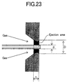
- the volume (corresponding to annular sectional area x thickness of orifice member) of the space shown in Fig. 23 is important for the purpose of forming the supersonic gas flow. It is desirable that the space volume per spray-gas flow rate equivalent to 1 L/min is set within the range of 3.6 x 10 6 to 5.1 x 10 6 ⁇ m 3 in each spray unit. When the space volume is less than or equal to 3.6 x 10 6 ⁇ m 3 , a supersonic gas flow cannot be formed unless a gas pressure of 7 times the atmospheric pressure or higher is applied. It is therefore necessary to form devices around the nebulizer as high-pressure resistant and sturdy ones.
- the entire system is brought into large size and high cost.
- the gas pressure is less than or equal to 7 times the atmospheric pressure, the generation of a supersonic gas flow having a flow velocity of Mach 2 or more is actually impossible in principle. Therefore, the gas pressure may desirably be used within a range from 1.9 to 7 times the atmospheric pressure, and the velocity of the generated gas flow falls within the range of Mach 1 to 2.
- the flow velocity of the gas is lowered, and hence no gas reaches the supersonic region.
- the flow rate of the gas normally ranges from 0.5 to 1.4 L/min. it is therefore necessary to set the total volume defined between the tube and the orifice to a range from 1.8 x 10 6 to 7.1 x 10 6 ⁇ m 3 .
- the length of the orifice at a portion where the tube and the orifice are closest to each other may be set to the thickness of the orifice member upon estimating the volume.
- the orifice member comprises a plate having a thickness of 0.2 mm.
- a nebulizer utilizing orifices and tubes of various sizes in combination was fabricated and installed in an analytical apparatus.
- the flow rate of the gas introduced into the nebulizer was kept substantially constant.
- the result thereof is collectively shown in Fig. 3.
- the annular sectional area in Fig. 3 corresponds to the annular sectional area of the gas flow in a region in which the tube and the orifice are closest to each other.
- the annular sectional area ( ⁇ (D 2 - d 2 )/4 ) is calculated by using the diameter D of each orifice and the diameter d of each tube.
- the inner diameter of the orifice is not always kept constant depending on processing means or the accuracy of processing in the case of the narrowest region (length t ) in which the gas passes through each orifice 4 as shown in Fig. 23.
- the inner diameter of the narrowest portion through which the gas passes is defined as D, and a region in which the inner diameter is greater than D by about 20%, is included in a region in which the thickness of the orifice member is t.
- the velocity of the spray gas reaches the supersonic region from the calculation of the slope or the inclination of the solid line shown in Fig. 3. It is desirable that since a processing error of about 10% is not often avoided, the annular sectional area is less than or equal to 2.53 x 10 4 ⁇ m 2 for the purpose of bringing the velocity into the supersonic region. It is necessary to set the entire system to a high-pressure resistant and sturdy one when gas pressure capable of being used for the nebulizer reaches a high pressure of 10 times the atmospheric pressure or higher.
- the area per spray-gas flow rate equivalent to 1 L/min is set to be within the range of 1.8 x 10 4 to 2.53 x 10 4 ⁇ m. While a plurality of tubes are used for the supersonic array nebulizer, a problem arises from the practical viewpoint in that there is a high possibility that when the inner diameter of each tube 5 is less than or equal to 5 ⁇ m, the tubes 5 will be clogged with particles such as dust. If the inner diameter is greater than or equal to 200 ⁇ m, the efficiency of tearing off the liquid lying in the center of each tube by the gas flow is reduced.
- each droplet generated from the nebulizer increases and the spray efficiency of the liquid discharged by spraying is degraded.
- the inner diameter of each tube 5 needs to fall within the range of 5 to 200 ⁇ m in order to obtain the high spray efficiency of the liquid.
- the spray efficiency of the liquid depends even on the flow rate of the liquid introduced into one tube 5. It is therefore desirable that the flow rate of the liquid per tube 5 is set to less than or equal to 100 ⁇ L/min. Further, the spray efficiency of the liquid discharged by spraying depends on the wall thickness (corresponding to 1/2 of the difference between the outer diameter and the inner diameter) of each tube 5.
- the tube thin in thickness is improved in spray efficiency. While, however, a problem normally arises in terms of the strength if the wall thickness does not reach a value greater than or equal to 5 ⁇ m, the spray efficiency is significantly reduced when the wall thickness is greater than or equal to 100 ⁇ m.
- the fixing plate 8 for fixing the position of each tube 5 is disposed at a distance of 1 to 15 mm as viewed from the orifice member 7. If set to greater than or equal to 20 mm, then the vibration of the tube 5 becomes pronounced and exerts a bad influence on spraying. There is a fear that when it is set to less than or equal to 1 mm, the fabrication of the nebulizer becomes difficult, and the pressure loss of the nebulizer gas becomes pronounced because the space defined between the fixing plate and each orifice is small.
- the orifice member 7 is provided with the three orifices.
- the holes equal to the same number as above are defined in the fixing plate 8.
- Each tube 5 is a molten silica capillary (flow path) whose outer diameter, inner diameter and length are respectively 127 ⁇ m, 50 ⁇ m and 80 mm.
- the three orifices 4 whose diameters are 170 ⁇ m, are defined in a disk 7 comprised of a stainless material whose surface having a thickness of 0.2 mm is subjected to corrosion-resistant coating and provided at the apexes of a triangle at 2-mm equal intervals.
- the distance between each orifice 4 and the fixing plate 8 is 5 mm.
- the tip or a leading portion or the end of the second member is cylindrical and has an outer diameter of 9 mm.
- the leading end thereof is inserted into a cover provided with a seal O-ring for a spray chamber cover to thereby connect the nebulizer and a spray chamber to each other.
- Fig. 4 shows the dependence of each signal intensity obtained by the plasma atomic emission analytical apparatus on each sample flow rate. If the spray efficiency is constant, then the sample flow rate and the signal intensity should be brought to a proportional relationship. However, since the spray efficiency is reduced as the sample flow rate increases in practice, the proportional relationship tends to disappear.
- a nebulizer usable for a high-sensitivity analysis does not exist in a sample flow-rate range of 100 to 300 ⁇ L/min as shown in the drawing.
- the flow rate of a liquid in a semi-microcolumn is about 200 ⁇ L/min, and the semi-microcolumn is coupled to the upstream side of the analytical apparatus to perform a chemical speciation analysis, the high-sensitivity analysis is actually difficult.
- the supersonic array nebulizer is used, the signal intensity significantly increases till an introduced sample flow rate of 300 ⁇ L/min.
- the maximum signal intensity can be increased to about twice.
- one nebulizer can cope with an extremely small flow rate to a few hundred ⁇ L/min if the supersonic array nebulizer is used.
- RSD relative standard deviation
- Table 1 a result of stability (RSD) of spraying relative to the liquid flow rate, which has been examined by ten times-continuous measurements, is shown in Table 1.
- RSD is shown as 2.61 at the maximum with respect to sample flow rates equivalent to 7 to 250 ⁇ L/min. This result shows that the nebulizer has a sufficiently high in stability within the above flow-rate range and can be used for quantitative analysis.
- FIG. 5 A schematic diagram of a supersonic array nebulizer based on another embodiment of the present invention is shown (in Fig. 5). While a basic structure is provided as shown in Fig. 1, Fig. 5 shows an example in which each orifice 4 makes use of one obtained by slicing a resin tube. Fig. 6 is an enlarged view of each orifice shown in Fig. 5.
- a plastic tube identical in the inner diameter (e.g., 170 ⁇ m) to the orifice 4 is cut with a thickness of 0.5 mm, and disks 14 for the resultant three plastic tubes are respectively fit in three holes defined in the leading end of a second member, which in turn are fixed with an adhesive. This corresponds to an orifice member whose diameter is 170 ⁇ m and whose thickness is 0.5 mm.
- the three orifices are provided at the apexes of a triangle at 4 mm equal intervals.
- Figs. 7 and 8 are respectively enlarged views of orifices of the supersonic array nebulizer based on another embodiment of the present invention.
- the basic structure of the nebulizer is similar to the embodiment shown in Fig. 5 but the orifice member 7 is fabricated with a ceramic material.
- a ruby orifice material 15 (whose diameter and thickness are 2 mm and 0.3 mm, respectively) having orifices each having an inner diameter of 170 ⁇ m is shown in Fig. 7.
- Three disks are respectively fixedly fit in three holes defined in a second member. The three orifices are fixed at 4-mm equal intervals.
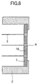
- a large ruby orifice member 16 (whose diameter and thickness are 6 mm and 0.3 mm, respectively) is shown in Fig. 8.
- a sample solution is first sprayed by a nebulizer to produce an aerosol.
- the aerosol is introduced into a plasma so as to be brought into atomization, excitation or ionization, whereby ions or radiation light is analyzed. It is therefore of importance that a fine aerosol is produced by the nebulizer and the sample is introduced into the plasma with satisfactory efficiency. Further, the introduction of a large quantity of solvent (molecules) into the plasma might exert a bad influence on the analysis thereof. Thus, there may be cases in which the solvents in the aerosol stand in need of their positive removal.
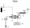
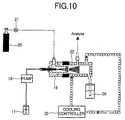
- FIGs. 9 and 10 are respectively configurational diagrams of a sample introduction system using the supersonic array nebulizer including a solvent removal process, based on one embodiment of the present invention.
- a sample solution 17 is introduced into a supersonic array nebulizer 19 by a pump 18. Therefore, the sample solution 17 is controlled to 5 times the atmospheric pressure by a pressure-reducing valve or regulator 21 and thereby sprayed by an introduced gas. Two kinds of methods of removing the solvent molecules in the aerosol are considered. In the solvent removing method shown in Fig.
- the aerosol is heated and thereby evaporated, followed by separation of the solvent through a membrane.
- a spray chamber 22 heated to about 150°C droplets in the aerosol are fully vaporized and introduced into a membrane separator 24.
- the membrane having the property of allowing only the solvents to pass therethrough is used to thereby remove the solvent molecules which interferes with the analysis.
- the remaining substances to be analyzed are introduced into the plasma together with a carrier gas, followed by atomization and ionization.
- a spray chamber 22 is cooled to - 5°C and subjected to evaporation to capture solvent molecules and droplets by the surface of the spray chamber 22. Owing to this function, the removal of the solvent molecules is implemented. (Embodiment 5)
- Fig. 11 is a configurational diagram of an inductively coupled plasma mass spectrometry (ICP-MS) system using the supersonic array nebulizer combined with a semi-microcolumn, based on one embodiment of the present invention.
- a sample solution 17 is subjected to chemical speciation separation or normal chemical separation and concentration by a semi-microcolumn 27 , followed by introduction into a supersonic array nebulizer 19. Therefore, the solution 17 is sprayed from a gas cylinder 20 through the use of a spray gas (4.5 times the atmospheric pressure) controlled by a pressure-reducing valve or regulator 21. Aerosol produced by spraying is introduced into a cooled spray chamber 22 to thereby remove solvents. Thereafter, the remaining aerosol is introduced into a plasma 28.
- ICP-MS inductively coupled plasma mass spectrometry
- Analyzed substances ionized by the plasma are fractionated and detected by a mass analyzer 29.
- the flow rate of the solution in a semi-microcolumn is normally about 200 ⁇ L/min and a concentric glass nebulizer is not capable of coping with it.
- the use of the supersonic array nebulizer allows the use of the semi-microcolumn. Owing to such a system, a chemical speciation analysis for, e.g., arsenic, selenium, etc. can be performed, and information about the level of toxicity as well as the total volume of elements can also be obtained.
- the system is expected to be widely applied in, for example, medical and toxicological fields starting with an environmental field.
- a valve 31 is switched to directly introduce the sample solution 17 delivered by a peristaltic pump 18 into the supersonic array nebulizer 19 as shown in Fig. 11.
- the spray chamber 22 is cooled to -5°C by a cooling controller 25 to thereby remove solvents.
- Analytical sensitivity is improved three times as compared with the use of the normally concentric nebulizer in which the sample flow rate is 400 ⁇ L/min.
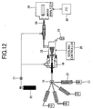
- Fig. 12 shows a system in which a large number of semi-microcolumns are coupled to the supersonic array nebulizer based on one embodiment of the present invention. While the separation of the columns normally needs a few minutes to several tens of minutes, the width of the time (bandpeak) required to elute a separated solution is about one minute. Therefore, the simultaneous use of the large number of semi-microcolumns at intervals of several minutes allows the implementation of a high-throughput analysis.
- Fig. 13 is a diagram showing an inductively coupled plasma mass spectrometry system using the supersonic array nebulizer based on another embodiment of the present invention.
- a three dimensional quadrupole (quadrupole ion trap) mass analyzer 34 is used as a mass analytical apparatus.
- Amass analytical unit comprises a pair of bowl-shaped end cap electrodes 35 and a doughnut-shaped ring electrode 36. When a high-frequency voltage V is applied to the ring electrode, ions each having a specific mass number or more are taken in the electrodes according to the applied voltage.
- the high-frequency voltage V is scanned from a low voltage to a high voltage to thereby sequentially destabilize the ions from the ions each having a low mass number.
- the ions are discharged outside the electrodes and detected.
- the mass number of each ion can be determined according to the relationship between the mass number of each detected ion and V.
- the determination of the quantity of each ion is implemented based on the detected signal intensity.
- a sample solution 17 and solvent (water) 33 are alternately introduced into a supersonic array nebulizer 19 by a flow injection apparatus 32 and sprayed therefrom. Generated aerosol is introduced into a spray chamber 22.
- the spray chamber 22 heated to 150°C by a heating controller 23, evaporated water molecules are removed by a separation membrane 24 which allows only water vapor to pass therethrough.
- the remaining substances to be analyzed are introduced into a plasma (ICP) 28 where they are ionized.
- the produced ions are introduced into the mass analyzer 34.
- the three dimensional quadrupole (quadrupole ion trap) mass analyzer is capable of dissociating molecular ions and removing different types of ions each having the same mass number. Further, a high-sensitivity analysis is realized owing to analyte enrichment based on the three dimensional quadrupole.
- the pressure of a spray gas is 4 times the atmospheric pressure, the flow rate of the spray gas is 1 L/min, and the flow rate of a sample to be introduced is 250 ⁇ L/min, the strength of each detected ion is increased to four times as compared with the use of a glass nebulizer in which the flow rate of the sample to be introduced is 400 ⁇ L/min.
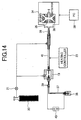
- Fig. 14 is a diagram showing an inductively coupled plasma mass spectrometry system for chemical speciation analysis, which uses the supersonic array nebulizer based on another embodiment of the present invention.
- the present system separates various chemical speciation substances according to capillary electrophoresis (CE) and detects the same by the ICP-MS.
- a sample containing AsO 2- , AsO 3- , SeO 3 2- , and SeO 4 2- is introduced into three separation capillaries 35 (whose outer and inner diameters are respectively 127 ⁇ m and 50 ⁇ m) having a length of 30 cm.
- One end of each capillary 37 is dipped into a buffer solution 38 and the other end thereof is dipped into a conductive auxiliary solution 39.
- a voltage of 10 to 25 kV is applied between both ends of each capillary by a high-voltage supply device 40 to thereby realize electrophoresis.
- the separated sample is introduced into a nebulizer 19 from which it is sprayed.
- aerosol is directly introduced into a plasma 28 through a connecting tube 41 to perform a sample analysis.
- the separation and detection of the above components are completed in about 15 minutes since the commencement of the electrophoresis.
- the limited concentration for their detection is about 0.08 ng/mL.
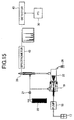
- Fig. 15 is a configurational diagram of an inductively coupled plasma atomic emission spectrometry system using the supersonic array nebulizer based on one embodiment of the present invention.
- a sample solution 17 is introduced into a supersonic array nebulizer 19 by a micro-tube pump 18.
- An argon spray gas in a gas cylinder 20 is controlled to 4 times the atmospheric pressure by a pressure-reducing valve or regulator 21 and supplied to the supersonic array nebulizer.
- a spray chamber 22 removes slightly large droplets contained in aerosol produced by spraying and discharges them into a waste reservoir 26. The remaining aerosol is introduced into a plasma 28.
- Substances to be analyzed are atomized by the plasma 28, followed by excitation and light-emission.
- the emitted light is wavelength-separated by a spectrometer 42 and detected by a detector 43.
- a personal computer 30 performs the control of the system and data processing.
- the relative standard deviation (RSD) obtained by ten times-continuous measurements is less than or equal to 1.5%.
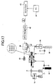
- Fig. 17 is a configurational diagram of an atomic absorption spectrometry system using the supersonic array nebulizer based on one embodiment of the present invention.
- a supporting gas (air) delivered at several tens of L/min is used as a spray gas and a solution sample is sprayed therethrough.
- a spray gas delivered from an air cylinder 44 is depressurized by a pressure-reducing valve or regulator 21 and introduced into a supersonic array nebulizer 45.
- a sample solution is introduced into the nebulizer 45 by self absorption and distributed to a plurality of tubes (capillaries) whose ends are inserted into plural orifices. The sample solution is sprayed therethrough by supersonic region supporting gas flows generated form the orifices.
- a spray chamber 22 removes relatively large droplets contained in aerosol and discharges them into a waste reservoir 26.
- a fuel gas delivered from an acetylene cylinder 46 is mixed with the aerosol within the spray chamber 22 and thereafter burned by a burner 47.
- a plasma (acetylene-air flame) 48 exceeding 2000°C droplets are vaporized and each substance to be analyzed is atomized.
- a radiation beam emitted from a hollow cathode lamp 49 is applied to the plasma (acetylene-air flame) 48, whereby the absorbance of the atomized substance to be analyzed is measured by a spectrometer 42 and a detector 43.
- the introduction of it by a peristaltic pump 18 can also be utilized as well as self absorption.
- the thickness of the orifice member is 1.5 mm.
- An array nebulizer comprising 16 molten silica tubes (whose inner and outer diameters are respectively 200 ⁇ m and 100 ⁇ m) and 16 orifices (whose inner diameters are respectively 250 ⁇ m) is mounted to a polarized Zeeman atomic absorption spectrometry system, and an evaluation experiment was done in this state.
- sensitivity similar to the normal nebulizer was obtained even though the flow rate of a sample fluid was 1 mL/min (1/5 of the normal flow rate).
- the analytical sensitivity of the atomic absorption spectrometry system was improved about twice as compared with the normal nebulizer from the result that a sample solution delivered at a flow rate of 5 ⁇ L/min has been introduced by the peristaltic pump 18.
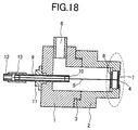
- Fig. 18 is a cross-sectional view of the supersonic nebulizer based on another embodiment of the present invention. While the present supersonic nebulizer is structurally similar to the nebulizer shown in Fig. 1, the number of spray units is one. However, the present nebulizer is also sprayed through a supersonic region gas.
- Fig. 19 is an enlarged view of the orifice shown in Fig. 18.
- Fig. 20 is similar to Fig. 18, but no fixing plate is used in Fig. 20.
- a tube 5 is supported by a fixing tube 9 extended to a position away 5 mm from a spray hole or port.
- Fig. 21 is a cross-sectional view of a supersonic array nebulizer based on a further embodiment of the present invention.
- a spray gas is introduced through a gas inlet 6 and circulated by a helical gas path. Further, the spray gas is injected from an orifice 4 and reaches a supersonic speed of Mach 1 or more.
- a sample solution delivered from an end of a tube 5 is sprayed by its supersonic gas flow. The distance between the end of the tube 5 and the outside of an orifice member is less than or equal to 2 mm.
- the surface of a liquid is torn off by the velocity of the gas lying in the direction of its injection without reflecting a shock wave of a supersonic gas flow to thereby produce fine droplets.
- the supersonic array nebulizer comprises the first member and the second member.
- the supersonic array nebulizer is assembled in accordance with a procedure for fixing each tube 5 to the second member and thereafter coupling it to the first member.
- a jig 51 is used in an assembly process.
- a cylinder having a height of L is provided in the center of the jig.
- a tip or leading end of the second member is inserted into the jig 51 without any clearance, and the surface of its leading end is brought into contact with the outer surface of the orifice member 7.
- the position of the end of each tube 5 can be brought into contact with the outer surface of the orifice member 7.
- the height of the cylinder of the jig 51 may be set smaller than L.
- the orifice member 7 is first fixed to the second member with an adhesive 10. Care is needed so as not to cause leakage of gas from the clearance or gap between the orifice member 7 and the second member.
- a fixing plate 8 is fixed with the adhesive 10.
- the tubes 5 are inserted into their corresponding orifices 4 and holes defined in the fixing plate 8, and hence the positions of the tubes 5 are determined by the jig 51. Further, each tube 5 is fixed to the fixing plate 8 with the adhesive 10.
- the tubes 5 are inserted into a fixing tube 9 fixed to the first member, and the adhesive is poured into clearances between the tubes 5 and the fixing tube 9 , whereby the first member and the second member are coupled to each other with the screw 3 (see Fig. 1). If they are fixed with the screw 3 before the setting of the adhesive, then the tube 5 is hard to break, thus providing convenience. Finally, the adhesive is buried in the clearance defined between the fixing tube 9 provided outside the first member and each tube 5 to hermetically seal the clearance. Hermetically sealing even both ends of the fixing tube 9 with the adhesive is necessary to prevent a high-pressure gas from leaking.
- the spraying of a liquid is efficiently performed using a gas flow lying in a supersonic region.
- a sample liquid is divided into a plurality of tubes (capillaries) and introduced therein. Further, the sample liquid is sprayed at the ends of the respective tubes through the use of a supersonic gas flow with high spray efficiency. Owing to this function, a reduction in spray efficiency is controlled even in the case of the high flow rate of the liquid. Particularly when it is utilized as a nebulizer for a high-sensitivity analytical apparatus, the sensitivity of the apparatus greatly increases.
Landscapes
- Health & Medical Sciences (AREA)
- Physics & Mathematics (AREA)
- Biochemistry (AREA)
- General Health & Medical Sciences (AREA)
- Nuclear Medicine, Radiotherapy & Molecular Imaging (AREA)
- Life Sciences & Earth Sciences (AREA)
- Chemical & Material Sciences (AREA)
- Analytical Chemistry (AREA)
- Engineering & Computer Science (AREA)
- Plasma & Fusion (AREA)
- General Physics & Mathematics (AREA)
- Immunology (AREA)
- Pathology (AREA)
- Other Investigation Or Analysis Of Materials By Electrical Means (AREA)
- Investigating, Analyzing Materials By Fluorescence Or Luminescence (AREA)
- Sampling And Sample Adjustment (AREA)
- Nozzles (AREA)
- Investigating Or Analysing Materials By Optical Means (AREA)
Abstract
Description
- The present invention relates to a nebulizer for spraying a liquid with high efficiency, and particularly to a nebulizer suitable for use in an inductively coupled plasma/mass spectrometry system (ICP-MS), an inductively coupled plasma (ICP) atomic emission spectrometry system and an atomic absorption spectrometry system used for inorganic substance analysis.
- In analytical apparatus for inductively coupled plasma-mass spectrometry (ICP-MS) , inductively coupled plasma atomic emission spectrometry (ICP-AES) , etc., aerosol is produced from a solution sample by a nebulizer and introduced into a plasma. Here, substances to be analyzed are brought into atomization, excitation and ionization. Owing to a mass analysis for the resultant ions or a spectrometric analysis for light emitted from excited atoms or ions, the identification and determination of each substance to be analyzed present in the liquid sample are realized. A concentric glass nebulizer is often used as the nebulizer. A description related to ICP-AES is disclosed in, for example, Analytical Chemistry 54(1982), p.533 - 537. At the end of each spray tube, atmospheric pressure becomes less than or equal to 1 atm by a spray gas. A difference in pressure between the two ends of the tubes is used so that the liquid sample is sucked into the nebulizer from a container. The flow rate of the gas is 1.0 L/min, and the flow rate of the liquid is about 1.0 mL/min.
- A micro concentric nebulizer (MCN) related to ICP-MS has been described in Journal of Analytical Atomic Spectrometry, 11(1996), p.713 - 720. A liquid sample is delivered to a single capillary and sprayed around its end by gas which passes therethrough. The flow rate of the gas is about 1.0 L/min. Since the velocity of the gas is faster than that for the concentric glass nebulizer, the efficiency of its spraying is relatively high. However, the introduced flow rate of a sample solution for realizing high-efficiency spraying is limited. The efficiency of the spraying is reduced when the flow rate thereof is 50 µL/min or more.
- There is need to prevent deposition of a metal due to heat generated upon cutting work, polishing, etc. Thus, a description related to a spray-like body supply device intended for cooling has been disclosed in Japanese Patent Application Laid-Open No. Hei 8-99051. If a liquid is produced or formed in spray form, then cooling can be carried out more effectively. The device has capillaries through which the liquid flows, and an injection hole (nozzle) from which a spray gas (air) is discharged. The cooling liquid is divided into a plurality of capillaries, and the ends of the plurality of capillaries are packed into a bundle. The liquid is sprayed at the ends thereof by an air flow discharged through one injection hole. The nozzle is shaped in tapered form.
- Japanese Patent Application Laid-Open No. Hei 7-306193 describes a sonic spray ionization technology. A quartz capillary (whose inner and outer diameters are 0.1 mm and 0.2 mm respectively) in which a liquid is introduced, has an end inserted into an orifice (whose inner diameter is 0.4 mm). A high-pressure nitrogen gas introduced inside an ion source is discharged into the air through the orifice, and the liquid is sprayed by a sonic gas flow formed at this time. Gaseous ions are produced in aerosol produced by the spraying. In the present ionizing method, the production of fine droplets by the sonic gas flow essentially plays an important role. The liquid in the sonic gas flow is torn off by a gas flow fast in velocity to thereby produce droplets. The non-uniformity of the concentrations of positive and negative ions in droplets firstly produced by spraying becomes pronounced as the size of each droplet becomes fine. Further, some of the liquid are separated from the surface of the droplet by a gas flow, whereby charged fine droplets are produced. Such fine droplets are evaporated in a short time so that gaseous ions are produced. While the size of each produced droplet decreases with an increase in the velocity of flow of gas, the droplet size increases as the velocity of flow of gas enters a supersonic region. This is because a shock wave is produced in the case of the supersonic flow, and the production of fine droplets is depressed. Therefore, according to the sonic spray ionizing method, when the gas flow is sonic, the finest droplets are produced and the produced amount of ions reaches the maximum. The present method discloses that when the flow rate of the spray gas is 3 L/min , a sonic gas flow is formed.
- A sonic spray nebulizer has been described in Analytical Chemistry, 71 (1999), p.427- 432. The nebulizer is similar in structure to the ion source for sonic spray ionization. The inner diameter of a resin orifice is 0.25 mm and a quartz capillary (whose inner and outer diameters are 0.05 mm and 0.15 mm respectively) is used. Since a sonic gas flow is used in a spray gas, the present nebulizer is capable of producing extremely fine droplets. As a result, the spray efficiency of a liquid is greatly improved as compared with the conventional glass nebulizer. In the sonic spray nebulizer, the flow rate of the gas is fixed to the condition for the generation of the sonic gas flow, and the flow rate of a liquid sample is controlled by a pump. The flow rate of the gas ranges from 1.0 L/min to 1.4 L/min, and the flow rate of the liquid ranges from 1 to 90 µL/min.
- On the other hand, a nebulizer using a supersonic gas flow has been described in Japanese Patent Application Laid-Open No. Hei 6-238211 and USP. No. 5,513798. The present nebulizer is characterized in that a supersonic gas flow is helically produced in the neighborhood of a liquid outlet at an end of a capillary by a helical gas path. Further, a cylindrical path is placed on the downstream side from an orifice unit and a shock wave of a supersonic gas flow is repeatedly reflected by the inner surface of the path. Since the shock wave collides with a liquid flow many times in an in-path central portion, droplets are efficiently produced from the liquid cut to pieces. The length (corresponding to the distance between the end of the capillary and the surface of the cylindrical path, which is brought into contact with the air). is as about twice as the diameter of the cylindrical path. The flow rate of gas ranges from 50 to 60 L/min , and the flow rate of the liquid ranges from 91 to 100 mL/min. Since the spray gas helically circles round, the formation of a gas flow concentrically with the capillary as described in the prior art is not carried out. The velocity of flow of the spray gas is divided or resolved into a horizontal direction and a vertical direction with respect to the axis of the capillary. While the velocity of flow of the gas is supersonic, a flow velocity component horizontal to the capillary axis is considered to be less than or equal to the speed of sound. In a droplet producing process, the application of the shock wave to the liquid is important and no emphasis is placed on the tearing off of the liquid by a high-speed gas flow.
- Upon vaporization of the liquid, the flow rate of fully-vaporizable water per gas flow rate 1 L/min is about 20 µL/min at most if calculated from saturated vapor pressure at 20°C. Therefore, if sample solution given at a flow rate of 20 µL/min or more is introduced into an ideal nebulizer when the flow rate of the gas is about 1L/min, then the efficiency of its spraying should have been reduced in the ideal nebulizer. However, an actual nebulizer shows a tendency to improve analytical sensitivity even if the sample flow rate is 20 µL/min or more. This is because the spray efficiency of the liquid is considered not to have reached an ideal level.
- In the concentric glass nebulizer, the flow rate of the liquid is about 500 µL/min when the liquid is automatically sucked. Therefore, the full vaporization of liquid cannot be carried out when the flow rate is a gas flow of about 1 L/min. Since a gas flow path is narrow and long structurally, the gas introduced into the nebulizer suffers a pronounced pressure loss in the neighborhood of a jet or injection port or outlet. As a result, the flow velocity of the spray gas is much slower than the speed of sound and the size of each produced droplet is about 10 µm. Most of droplets produced by spraying are coagulated or condensed, whereby they are released from aerosol so as to return to the liquid. Therefore, the spray efficiency of the liquid become extremely low and reaches 1% to 3%. Further, the nebulizer is capable of suitably setting the flow rate of a sample solution through the use of a pump. However, a problem arises in that when the flow rate of the sample solution to be introduced is 300 µL/min or less, the spraying becomes unstable and hence the nebulizer cannot be used. Therefore, the nebulizer cannot be coupled or linked to a semi-micro liquid chromatographor (liquid flow rate of about 200 µL/min). (An elementary analytical apparatus might be used to perform a chemical speciation analysis as well as an elementary analysis. In this case, a sample liquid is separated according to the semi-micro liquid chromatography and the separated liquid is introduced into the nebulizer). Even if the flow rate of the liquid sample is increased in the range of 400 to 1000 µL/min, the sensitivity of the analytical apparatus little increases. This shows that the substantial amount of the sample introduced into a plasma does not increase.
- The micro concentric nebulizer is different from the concentric glass nebulizer, and reduces the flow rate of the liquid sample and improves the efficiency of its spraying. This is because the flow velocity of the gas is considered to be high as compared with the concentric glass nebulizer. Therefore, the micro concentric nebulizer is characterized in that a liquid sample available by a small quantity can be analyzed. However, the flow rate of a liquid sample, which allows the maintenance of high spray efficiency, is less than or equal to 50 µL/min. When the flow rate thereof is greater than that, the sensitivity of the analytical apparatus little increases. As a result, the micro concentric nebulizer is accompanied by a problem in that when liquid samples identical in concentration are analyzed, the sensitivity of the analytical apparatus is low as compared with the use of the concentric glass nebulizer. A problem arises in that particularly when a chemical speciation analysis which uses a semi-micro liquid chromatograph jointly, is performed, the flow rate of a liquid reaches about 200 µL/min and the sensitivity of the analytical apparatus is insufficient.
- The sonic spray nebulizer has a problem similar to the micro concentric nebulizer. While the present sonic spray nebulizer is a nebulizer capable of introducing a liquid given at a low flow rate with high efficiency, it uses a sonic gas flow for the purpose of liquid spraying. Since a wide gas flow path is provided therein, a pressure loss of gas is very low and the sonic gas flow can easily be formed. Further, since the end of a capillary in which the liquid is introduced, is placed in the center of an orifice used as a gas jet port or outlet, the efficiency of spraying is extremely high. However, the flow rate of a liquid sample, which allows the implementation of high spray efficiency, is about 60 µL/min or less in the sonic spray nebulizer in a manner similar to the micro concentric nebulizer. When the flow rate is greater than that, the spray efficiency is reduced and the sensitivity of an analytical apparatus does not increase significantly.
- As described above, the liquid is sprayed through the use of the high-speed (sonic) gas flow in the concentric glass nebulizer, the micro concentric nebulizer, and the sonic spray nebulizer. These nebulizers are respectively accompanied by a problem in that while spraying is carried out through the single jet or injection port or outlet, the spray efficiency is reduced with an increase in flow rate when the liquid flow rate is greater than or equal to about 60 µL/min. When they are installed in a plasma mass analyzer or a plasma atomic emission spectrometry system, it is necessary to properly use nebulizers such as a glass nebulizer, etc. according to the flow rate of the liquid sample, thus causing inconvenience. Particularly when the chemical speciation analysis is done which uses jointly a semi-micro liquid chromatograph in which the liquid flow rate is about 200 µL/min , a problem arises in that, for example, the spraying becomes unstable, thereby making each nebulizer incapable of use, and the spray efficiency becomes low.
- As indicated by the sonic spray ionization technology, the size of each produced droplet depends on the gas flow rate. When the flow rate of the spray gas is sufficiently high, the spray efficiency reaches the maximum in the case of the sonic gas flow owing to the effects of tearing off the liquid by the sonic gas flow, and hence the spray efficiency of the liquid becomes high. Japanese Patent Application Laid-Open No. Hei 9-239298 discloses that when the gas flow rate is 3 L/min, a sonic gas flow is formed. Thus, when no limitation is imposed on the gas flow rate relative to the liquid flow rate, the size of each of droplets produced by spraying reaches the minimum upon the speed of sound, and hence droplets each having a sub-micron size of about 0.7 µm are produced in large quantities. When a gas flow slightly faster than the speed of sound is used,- the size of each droplet actually tends to increase on the average, but droplets of sub-micron sizes are produced. However, a limitation is often imposed on the flow rate of a usable spray gas in an actually-used nebulizer. In the plasma atomic emission or mass spectrometry system, for example, the flow rate of the spray gas is required to be set to about 1 L/min. A restriction is imposed on the gas flow rate relative to the liquid flow rate in order to increase the spray efficiency of a liquid to the maximum under the condition that the gas flow rate is kept constant. As a result, the size of each droplet reaches the minimum where a supersonic gas flow other than the sonic gas flow is formed. This is because even if a shock wave for restraining or controlling the scale-down of each droplet is formed, the production of fine droplets by a gas-flow tearing-off effect becomes effective if a gas flow faster than the speed of sound is formed. Namely, it is desirable that the velocity of flow of the gas is supersonic rather than sonic or less in order to produce droplets each having a sub-micron size in large quantities at a constant gas flow rate and increase the spray efficiency of the liquid to the maximum.
- In the nebulizer described in USP. No. 5,513,798 which aims to spray a large quantity of liquid in a large quantity of gas, a supersonic spray gas flow is used. In the present nebulizer, the gas flow is not formed concentrically with the capillary as described in the prior art, and the spray gas helically circles round. Droplets of 2 µm to 10 µm are produced by applying a shock wave to the liquid without using the effects of tearing off the liquid by a high-speed gas flow. Since each droplet is large and in micron size, it is difficult to implement an increase in the sensitivity of each system even if the present nebulizer is used as nebulizer for a spectrometry system and a measuring system. Further, since the helical gas flow is formed, the gas flow path is structurally narrow and complex, and the pressure of gas introduced into the nebulizer reaches a significantly high pressure. A problem arises in terms of fabrication upon applying such a nebulizer to the case where the gas flow is low. While the gas flow rate is set to 1 L/min in the nebulizers for the ICP atomic emission spectrometry system and the ICP-MS in particular, it is extremely difficult to fabricate a nebulizer which copes with such a low gas flow rate. This is because the gas flow path needs high-accuracy micro-fabrication for the purpose of forming the helical gas flow. A problem arises in that since the high-pressure gas is used, a gas supply means as well as the nebulizer also needs to have high pressure resistance.
- In the nebulizer described in Japanese Patent Application Laid-Open No. Hei 8-99051, the introduced liquid is divided into the large number-of capillaries. The ends of the large number of capillaries are packed into the bundle, and the liquid is sprayed by the gas flow discharged from one jet or injection port or outlet. However, the capillaries lying in the center of the bundle are hard to contact the gas flow, and the spray efficiency becomes relatively low. The structure of the nozzle shaped in tapered form leads to a noticeable pressure loss, and a high-speed gas flow is hard to occur.
- In the conventional nebulizers as described above up to now, a sufficient spray efficiency was not always obtained and a limitation was imposed on the applicable liquid flow-rate range from the viewpoint of the production of the droplets of sub-micron sizes in large quantities.
- It is the problem underlying the present invention to provide a nebulizer with high spray efficiency, which is capable of producing droplets of sub-micron sizes in large quantities within a wide range of liquid flow rates at a limited gas flow rate.
- The above problem is solved according to the independent claim. The dependent claims relate to preferred embodiments.
- In order to solve the above problems, the present invention provides a nebulizer which effectively makes use of the momentum of a gas flow for purposes of liquid spraying by using a supersonic spray gas flow lying in the axial direction of a capillary (flow path). Further, the present invention provides a nebulizer provided with a plurality of spray units.
- How to increase an opportunity to allow a spray gas and a liquid to collide with each other in a limited time or space is of extreme importance when spraying the liquid using a compressed gas. Therefore, the solution and gas are uniformly distributed to each individual spray units to thereby make it possible to increase the probability of contact between the solution and the gas. When the limited spray gas is distributed to the respective spray units, the flow rate thereof is greatly reduced. In order to improve, the effects of making collision between the spray gas and the liquid, a supersonic gas flow having much momentum as compared with a sonic gas flow is used. As a result, fine droplets can be produced with satisfactory efficiency.
-
- Fig. 1 is a cross-sectional illustration of the supersonic array nebulizer;
- Fig. 2 is an enlarged illustration of a part of the nebulizer in Fig. 1;
- Fig. 3 shows the relationship between the flow rate of nebulizer gas and the annular area for ejection of nebulizer gas;
- Fig. 4 is a comparison of the variation of the signal intensity at different sample uptake rates for the supersonic spray array nebulizer, the sonic spray nebulizer and the conventional concentric nebulizer;
- Fig. 5 is a cross-sectional illustration of the supersonic spray array nebulizer with orifices formed by using pieces of resin tube;
- Fig. 6 is an enlarged illustration of a part of the nebulizer in Fig. 5;
- Fig. 7 is an enlarged illustration of the supersonic spray array nebulizer whose orifices are formed in disk pieces of ceramic material;
- Fig. 8 is an enlarged illustration of the supersonic spray array nebulizer whose orifices are formed in a single piece of ceramic material disk;
- Fig. 9 shows a sample introduction system in which the supersonic spray array nebulizer is combined with a membrane separator for solvent removal;
- Fig. 10 shows a sample introduction system in which the supersonic spray array nebulizer is combined with a cooling device for solvent removal;
- Fig. 11 is a schematic diagram of an inductively coupled plasma mass spectrometry system in which a semi-microcolumn is connected with the supersonic spray array nebulizer;
- Fig. 12 is a schematic diagram of an analytical instrument system which includes several semi-microcolumns connected with the supersonic spray array nebulizer;
- Fig. 13 is a schematic diagram of an inductively coupled plasma mass spectrometry system which employs the supersonic spray array nebulizer combined with a flow injection equipment;
- Fig. 14 is a schematic diagram of an inductively coupled plasma mass spectrometry system which employs the supersonic spray array nebulizer combined with an electrophoresis device for chemical speciation analysis;
- Fig. 15 is a schematic diagram showing the use of the supersonic spray array nebulizer for an inductively coupled plasma atomic emission spectrometry system;
- Fig. 16 shows experimental results obtained with the inductively coupled plasma atomic emission spectrometry system which employs the supersonic spray array nebulizer for sample introduction;
- Fig. 17 is a schematic diagram of an atomic absorption spectrometry system which employs the supersonic spray array nebulizer for sample introduction;
- Fig. 18 is a cross-sectional illustration of a supersonic spray nebulizer with a single orifice;
- Fig. 19 is an enlarged illustration of part of the nebulizer described in Fig. 18;
- Fig. 20 is a cross-sectional illustration of a single-orifice supersonic spray nebulizer without using a plate to fix the tube;
- Fig. 21 is a cross-sectional illustration of a sonic spray nebulizer with a helical flow path for nebulizer gas;
- Fig. 22 is a pictorial illustration of the supersonic spray array nebulizer with a tool; and
- Fig. 23 is a pictorial illustration of part of the nebulizer for gas ejection.
-
- Preferred embodiments of the present invention will hereinafter be described in detail with reference to the accompanying drawings.
- Fig. 1 is a cross-sectional view of a supersonic array nebulizer based on one embodiment of the present invention. Fig. 2 is an enlarged view of orifices shown in Fig. 1. The present supersonic array nebulizer is characterized in that it sprays a supersonic region gas and has a plurality of spray units. Each of the spray units comprises an
orifice 4 through which a spray gas or pressurized gas is discharged, and a tube (capillary) 5 through which a sample liquid is introduced. The supersonic region spray gas is injected or delivered through a clearance (jet outlet or tip) defined between theorifice 4 and thetube 5. The liquid sample is divided into several spray units and simultaneously sprayed. Since the flow rate of the liquid sample introduced into each individual units is reduced as compared with the single spray unit, high-efficiency spraying is implemented as a whole. The liquid flow-rate range, which allows the implementation of the high-efficiency spraying, is enlarged. - The supersonic array nebulizer is formed by connecting a
first member 1 to asecond member 2 with ascrew 3. The terminal or end portion of eachtube 5 into which the sample liquid is introduced, is inserted into eachorifice 4. The end portion of eachtube 5 is placed on substantially the same surface as the outside of theorifice 4. A gas supplied from a gas supply means is introduced through agas inlet 6 and delivered from theorifice 4 to thereby spray the liquid. Eachtube 5 is fixed by a fixingplate 8 placed on the upstream side of anorifice member 7. In order to introduce the spray gas into theorifice member 7 , the fixing plate-8 is provided with gas pass-through portions. Further, thetubes 5 are fixed to a fixingtube 9 with an adhesive 10 to thereby prevent leakage of spray gas to the outside of the nebulizer and leakage of a liquid solution through the gap or clearance defined between thetube 5 and thetube 9. - The fixing
tube 9 is connected to thefirst member 1 through aflange 11 and to the sampleliquid introduction tube 12 through a connectingtube 13. - Since the gas flow path is wide inside the nebulizer using the
first member 1 and thesecond member 2, little gas pressure loss is produced between the gas supply means and theorifice 4. When the pressure of the gas supplied from the gas supply means is 5 times the atmospheric pressure (in particular 1 atm), the pressure inside the nebulizer becomes 4.8 times the atmospheric pressure. The thickness of theorifice member 7 is normally less than or equal to 1.5 mm. In the structure referred to above, a supersonic region gas flow can be formed through theorifice member 7 if the pressure of a gas source is set to about 4 to 5 times the atmospheric pressure. It is considered in such a nebulizer that the effect of tearing off the liquid by a high-speed gas flow acts effectively, and droplets of sub-micron sizes can be produced in large quantities. - The flow rate of a spray gas applied to a plasma atomic emission analytical system normally ranges from 0.5 L/min through 1.5 L/min and is placed under severe limitations. It is desirable that when consideration is given to the saturation vapor pressure of water, the velocity of flow of a gas falls within the supersonic region when the ratio between the flow rate of the liquid and the flow rate of the gas is greater than 5 x 10⁻⁵. A larger quantity of energy can be used for liquid spraying and hence the efficiency of spraying can be improved.
- The velocity of flow of the spray gas discharged from the orifice depends on the gas pressure on the upstream side of the orifice, the thickness of the orifice member, etc. When the thickness of the
orifice member 7 is negligible, the velocity of flow of the spray gas reaches substantially the velocity of sound (Mach 1) when the gas pressure on the upstream side of the orifice reaches 1.9 times the atmospheric pressure. When the gas pressure reaches 7.8 times the atmospheric pressure, a supersonic flow ofMach 2 is formed. However, when the thickness of the orifice member is greater than or equal to 2 mm, a significant pressure loss of the gas at the orifice member is produced. Thus, no sonic gas flow is formed unless the gas pressure on the upstream side of the orifice is set to an extremely high pressure. Higher pressure is required to form the supersonic flow. A gas supply unit such as a regulator of a commonly-used gas cylinder is set to a gas pressure corresponding to about 5 times the atmospheric pressure at most. Therefore, the thickness of the orifice may desirably be 1.5 mm or less. On the other hand, a problem arises in that when the thickness of the orifice member is less than or equal to 0.1 mm, it breaks from the viewpoint of strength. It is therefore desirable that the thickness of theorifice member 7 ranges from 0.1 to 1.5 mm. In the present embodiment, the thickness of the orifice member was set to 0.2 mm, and the gas pressure at the gas supply unit was set to 5 times the atmospheric pressure. - The spray gas is injected through the clearance (space) between the
orifice 4 and thetube 5. The volume (corresponding to annular sectional area x thickness of orifice member) of the space shown in Fig. 23 is important for the purpose of forming the supersonic gas flow. It is desirable that the space volume per spray-gas flow rate equivalent to 1 L/min is set within the range of 3.6 x 10⁶ to 5.1 x 106 µm3 in each spray unit. When the space volume is less than or equal to 3.6 x 106 µm3, a supersonic gas flow cannot be formed unless a gas pressure of 7 times the atmospheric pressure or higher is applied. It is therefore necessary to form devices around the nebulizer as high-pressure resistant and sturdy ones. Thus, the entire system is brought into large size and high cost. On the other hand, when the gas pressure is less than or equal to 7 times the atmospheric pressure, the generation of a supersonic gas flow having a flow velocity ofMach 2 or more is actually impossible in principle. Therefore, the gas pressure may desirably be used within a range from 1.9 to 7 times the atmospheric pressure, and the velocity of the generated gas flow falls within the range ofMach 1 to 2. - On the other hand, when the space volume is greater than or equal to 5.1 x 106 µm3, the flow velocity of the gas is lowered, and hence no gas reaches the supersonic region. In a nebulizer employed in a commonly-used plasma mass analytical apparatus or plasma atomic emission analytical apparatus, the flow rate of the gas normally ranges from 0.5 to 1.4 L/min. it is therefore necessary to set the total volume defined between the tube and the orifice to a range from 1.8 x 10⁶ to 7.1 x 106 µm3. Incidentally, the length of the orifice at a portion where the tube and the orifice are closest to each other, may be set to the thickness of the orifice member upon estimating the volume. In the present embodiment, the orifice member comprises a plate having a thickness of 0.2 mm.
- An evaluation was performed in a state in which when the thickness t of the orifice member is less than or equal to 1.5 mm, a nebulizer utilizing orifices and tubes of various sizes in combination, was fabricated and installed in an analytical apparatus. The flow rate of the gas introduced into the nebulizer was kept substantially constant. The result thereof is collectively shown in Fig. 3. The annular sectional area in Fig. 3 corresponds to the annular sectional area of the gas flow in a region in which the tube and the orifice are closest to each other. The annular sectional area (
orifice 4 as shown in Fig. 23. According to the result shown in Fig. 3, the inner diameter of the narrowest portion through which the gas passes, is defined as D, and a region in which the inner diameter is greater than D by about 20%, is included in a region in which the thickness of the orifice member is t. Data obtained from an example illustrative of a nebulizer in which a satisfactory result was not obtained, are respectively indicated with symbols A and B. In the case of A, the area per spray-gas flow rate equivalent to 1 L/min is 6.2 x 104 µm2. It was revealed that the size of spray was large and the efficiency of spraying was low. If the area is reduced to 3.5 x 104 µm2 (above B), then the efficiency of spraying is improved and the size of spray becomes much finer. However, if compared with the results placed below the solid line as a result of the execution of evaluation experiments under the installation of a nebulizer satisfying the condition of B in a plasma emission analyzer, then the sensitivity of its analysis was only the half thereof. If the area per spray-gas flow rate equivalent to 1 L/min is less than or equal to 2.3 x 104 µm2, the velocity of the spray gas reaches the supersonic region from the calculation of the slope or the inclination of the solid line shown in Fig. 3. It is desirable that since a processing error of about 10% is not often avoided, the annular sectional area is less than or equal to 2.53 x 104 µm2 for the purpose of bringing the velocity into the supersonic region. It is necessary to set the entire system to a high-pressure resistant and sturdy one when gas pressure capable of being used for the nebulizer reaches a high pressure of 10 times the atmospheric pressure or higher. It is desirable that if it is taken into consideration, then the area per spray-gas flow rate equivalent to 1 L/min is set to be within the range of 1.8 x 10⁴ to 2.53 x 104 µm.
While a plurality of tubes are used for the supersonic array nebulizer, a problem arises from the practical viewpoint in that there is a high possibility that when the inner diameter of eachtube 5 is less than or equal to 5 µm, thetubes 5 will be clogged with particles such as dust. If the inner diameter is greater than or equal to 200 µm, the efficiency of tearing off the liquid lying in the center of each tube by the gas flow is reduced. As a result, the size of each droplet generated from the nebulizer increases and the spray efficiency of the liquid discharged by spraying is degraded. This is because the more the size of each droplet becomes fine, the more the liquid is easy to be vaporized. Therefore, the inner diameter of eachtube 5 needs to fall within the range of 5 to 200 µm in order to obtain the high spray efficiency of the liquid. Further, the spray efficiency of the liquid depends even on the flow rate of the liquid introduced into onetube 5. It is therefore desirable that the flow rate of the liquid pertube 5 is set to less than or equal to 100 µL/min. Further, the spray efficiency of the liquid discharged by spraying depends on the wall thickness (corresponding to 1/2 of the difference between the outer diameter and the inner diameter) of eachtube 5. The tube thin in thickness is improved in spray efficiency. While, however, a problem normally arises in terms of the strength if the wall thickness does not reach a value greater than or equal to 5 µm, the spray efficiency is significantly reduced when the wall thickness is greater than or equal to 100 µm. The fixingplate 8 for fixing the position of eachtube 5 is disposed at a distance of 1 to 15 mm as viewed from theorifice member 7. If set to greater than or equal to 20 mm, then the vibration of thetube 5 becomes pronounced and exerts a bad influence on spraying. There is a fear that when it is set to less than or equal to 1 mm, the fabrication of the nebulizer becomes difficult, and the pressure loss of the nebulizer gas becomes pronounced because the space defined between the fixing plate and each orifice is small. - In the present embodiment, the
orifice member 7 is provided with the three orifices. The holes equal to the same number as above are defined in the fixingplate 8. Eachtube 5 is a molten silica capillary (flow path) whose outer diameter, inner diameter and length are respectively 127 µm, 50 µm and 80 mm. The threeorifices 4 whose diameters are 170 µm, are defined in adisk 7 comprised of a stainless material whose surface having a thickness of 0.2 mm is subjected to corrosion-resistant coating and provided at the apexes of a triangle at 2-mm equal intervals. The distance between eachorifice 4 and the fixingplate 8 is 5 mm. The tip or a leading portion or the end of the second member is cylindrical and has an outer diameter of 9 mm. The leading end thereof is inserted into a cover provided with a seal O-ring for a spray chamber cover to thereby connect the nebulizer and a spray chamber to each other.
Fig. 4 shows the dependence of each signal intensity obtained by the plasma atomic emission analytical apparatus on each sample flow rate. If the spray efficiency is constant, then the sample flow rate and the signal intensity should be brought to a proportional relationship. However, since the spray efficiency is reduced as the sample flow rate increases in practice, the proportional relationship tends to disappear. Even if a sample flow rate of a glass concentric nebulizer is increased to 300 to 400 µL/min , the signal intensity (sensitivity of analytical apparatus) does not increase so far. Particularly when the sample flow rate is 400 µL/min or more, the signal intensity little increases. On the other hand, when the sample flow rate is 300 µL/min or less, spraying becomes unstable and the analysis thereof becomes difficult. While a sonic spray nebulizer is capable of spraying a sample small in flow rate with high efficiency, the signal intensity of the analytical apparatus little increases when the sample flow rate is greater than or equal to 60µL/min. As a result, a problem arises in that a nebulizer usable for a high-sensitivity analysis does not exist in a sample flow-rate range of 100 to 300 µL/min as shown in the drawing. When, for example, the flow rate of a liquid in a semi-microcolumn is about 200 µL/min, and the semi-microcolumn is coupled to the upstream side of the analytical apparatus to perform a chemical speciation analysis, the high-sensitivity analysis is actually difficult. When the supersonic array nebulizer is used, the signal intensity significantly increases till an introduced sample flow rate of 300 µL/min. As compared with the glass concentric nebulizer, it is shown that when the supersonic array nebulizer is used, the maximum signal intensity can be increased to about twice. As described above, one nebulizer can cope with an extremely small flow rate to a few hundred µL/min if the supersonic array nebulizer is used. It has been recognized that when a relative standard deviation (RSD) of each signal intensity is less than or equal to 3%, the analytical apparatus can be used for quantitative analysis. Therefore, a result of stability (RSD) of spraying relative to the liquid flow rate, which has been examined by ten times-continuous measurements, is shown in Table 1. RSD is shown as 2.61 at the maximum with respect to sample flow rates equivalent to 7 to 250 µL/min. This result shows that the nebulizer has a sufficiently high in stability within the above flow-rate range and can be used for quantitative analysis. - A schematic diagram of a supersonic array nebulizer based on another embodiment of the present invention is shown (in Fig. 5). While a basic structure is provided as shown in Fig. 1, Fig. 5 shows an example in which each
orifice 4 makes use of one obtained by slicing a resin tube. Fig. 6 is an enlarged view of each orifice shown in Fig. 5. A plastic tube identical in the inner diameter (e.g., 170 µm) to theorifice 4 is cut with a thickness of 0.5 mm, anddisks 14 for the resultant three plastic tubes are respectively fit in three holes defined in the leading end of a second member, which in turn are fixed with an adhesive. This corresponds to an orifice member whose diameter is 170 µm and whose thickness is 0.5 mm. The three orifices are provided at the apexes of a triangle at 4 mm equal intervals. - Figs. 7 and 8 are respectively enlarged views of orifices of the supersonic array nebulizer based on another embodiment of the present invention. The basic structure of the nebulizer is similar to the embodiment shown in Fig. 5 but the
orifice member 7 is fabricated with a ceramic material. A ruby orifice material 15 (whose diameter and thickness are 2 mm and 0.3 mm, respectively) having orifices each having an inner diameter of 170 µm is shown in Fig. 7. Three disks are respectively fixedly fit in three holes defined in a second member. The three orifices are fixed at 4-mm equal intervals. On the other hand, a large ruby orifice member 16 (whose diameter and thickness are 6 mm and 0.3 mm, respectively) is shown in Fig. 8. - In an apparatus for plasma emission analysis and plasma mass analysis, a sample solution is first sprayed by a nebulizer to produce an aerosol. Next, the aerosol is introduced into a plasma so as to be brought into atomization, excitation or ionization, whereby ions or radiation light is analyzed. It is therefore of importance that a fine aerosol is produced by the nebulizer and the sample is introduced into the plasma with satisfactory efficiency. Further, the introduction of a large quantity of solvent (molecules) into the plasma might exert a bad influence on the analysis thereof. Thus, there may be cases in which the solvents in the aerosol stand in need of their positive removal. This is because the temperature of the plasma is lowered due to the large quantity of solvents, and the production of molecular ions derived from the solvents and the radiation from solvent molecules cause a reduction in analytical sensitivity. Figs. 9 and 10 are respectively configurational diagrams of a sample introduction system using the supersonic array nebulizer including a solvent removal process, based on one embodiment of the present invention. A
sample solution 17 is introduced into asupersonic array nebulizer 19 by apump 18. Therefore, thesample solution 17 is controlled to 5 times the atmospheric pressure by a pressure-reducing valve orregulator 21 and thereby sprayed by an introduced gas. Two kinds of methods of removing the solvent molecules in the aerosol are considered. In the solvent removing method shown in Fig. 9, the aerosol is heated and thereby evaporated, followed by separation of the solvent through a membrane. In aspray chamber 22 heated to about 150°C, droplets in the aerosol are fully vaporized and introduced into amembrane separator 24. The membrane having the property of allowing only the solvents to pass therethrough is used to thereby remove the solvent molecules which interferes with the analysis. The remaining substances to be analyzed are introduced into the plasma together with a carrier gas, followed by atomization and ionization. On the other hand, in the method shown in Fig. 10, aspray chamber 22 is cooled to - 5°C and subjected to evaporation to capture solvent molecules and droplets by the surface of thespray chamber 22. Owing to this function, the removal of the solvent molecules is implemented. (Embodiment 5) - Fig. 11 is a configurational diagram of an inductively coupled plasma mass spectrometry (ICP-MS) system using the supersonic array nebulizer combined with a semi-microcolumn, based on one embodiment of the present invention. A
sample solution 17 is subjected to chemical speciation separation or normal chemical separation and concentration by asemi-microcolumn 27 , followed by introduction into asupersonic array nebulizer 19. Therefore, thesolution 17 is sprayed from agas cylinder 20 through the use of a spray gas (4.5 times the atmospheric pressure) controlled by a pressure-reducing valve orregulator 21. Aerosol produced by spraying is introduced into a cooledspray chamber 22 to thereby remove solvents. Thereafter, the remaining aerosol is introduced into aplasma 28. Analyzed substances ionized by the plasma are fractionated and detected by amass analyzer 29. The flow rate of the solution in a semi-microcolumn is normally about 200 µL/min and a concentric glass nebulizer is not capable of coping with it. The use of the supersonic array nebulizer allows the use of the semi-microcolumn. Owing to such a system, a chemical speciation analysis for, e.g., arsenic, selenium, etc. can be performed, and information about the level of toxicity as well as the total volume of elements can also be obtained. The system is expected to be widely applied in, for example, medical and toxicological fields starting with an environmental field. When the separation of the column is not required, avalve 31 is switched to directly introduce thesample solution 17 delivered by aperistaltic pump 18 into thesupersonic array nebulizer 19 as shown in Fig. 11. Thespray chamber 22 is cooled to -5°C by a coolingcontroller 25 to thereby remove solvents. Analytical sensitivity is improved three times as compared with the use of the normally concentric nebulizer in which the sample flow rate is 400 µL/min. - Fig. 12 shows a system in which a large number of semi-microcolumns are coupled to the supersonic array nebulizer based on one embodiment of the present invention. While the separation of the columns normally needs a few minutes to several tens of minutes, the width of the time (bandpeak) required to elute a separated solution is about one minute. Therefore, the simultaneous use of the large number of semi-microcolumns at intervals of several minutes allows the implementation of a high-throughput analysis.
- Fig. 13 is a diagram showing an inductively coupled plasma mass spectrometry system using the supersonic array nebulizer based on another embodiment of the present invention. A three dimensional quadrupole (quadrupole ion trap)
mass analyzer 34 is used as a mass analytical apparatus. Amass analytical unit comprises a pair of bowl-shapedend cap electrodes 35 and a doughnut-shapedring electrode 36. When a high-frequency voltage V is applied to the ring electrode, ions each having a specific mass number or more are taken in the electrodes according to the applied voltage. After the completion of capturing of the ions, the high-frequency voltage V is scanned from a low voltage to a high voltage to thereby sequentially destabilize the ions from the ions each having a low mass number. Thereafter, the ions are discharged outside the electrodes and detected. The mass number of each ion can be determined according to the relationship between the mass number of each detected ion and V. The determination of the quantity of each ion is implemented based on the detected signal intensity. In the present system, asample solution 17 and solvent (water) 33 are alternately introduced into asupersonic array nebulizer 19 by aflow injection apparatus 32 and sprayed therefrom. Generated aerosol is introduced into aspray chamber 22. In thespray chamber 22 heated to 150°C by aheating controller 23, evaporated water molecules are removed by aseparation membrane 24 which allows only water vapor to pass therethrough. The remaining substances to be analyzed are introduced into a plasma (ICP) 28 where they are ionized. The produced ions are introduced into themass analyzer 34. The three dimensional quadrupole (quadrupole ion trap) mass analyzer is capable of dissociating molecular ions and removing different types of ions each having the same mass number. Further, a high-sensitivity analysis is realized owing to analyte enrichment based on the three dimensional quadrupole. When the pressure of a spray gas is 4 times the atmospheric pressure, the flow rate of the spray gas is 1 L/min, and the flow rate of a sample to be introduced is 250 µL/min, the strength of each detected ion is increased to four times as compared with the use of a glass nebulizer in which the flow rate of the sample to be introduced is 400 µL/min. - Fig. 14 is a diagram showing an inductively coupled plasma mass spectrometry system for chemical speciation analysis, which uses the supersonic array nebulizer based on another embodiment of the present invention. The present system separates various chemical speciation substances according to capillary electrophoresis (CE) and detects the same by the ICP-MS. A sample containing AsO2-, AsO3-, SeO3 2-, and SeO4 2- is introduced into three separation capillaries 35 (whose outer and inner diameters are respectively 127 µm and 50 µm) having a length of 30 cm. One end of each capillary 37 is dipped into a
buffer solution 38 and the other end thereof is dipped into a conductiveauxiliary solution 39. A voltage of 10 to 25 kV is applied between both ends of each capillary by a high-voltage supply device 40 to thereby realize electrophoresis. The separated sample is introduced into anebulizer 19 from which it is sprayed. In order to prevent a reduction in high resolution obtained by the electrophoresis, aerosol is directly introduced into aplasma 28 through a connectingtube 41 to perform a sample analysis. In an example experimented under the condition that the buffer solution comprises NaH2PO4 whose concentration is 0.075 mol/L and Na2B4O7 (pH = 7.65) whose concentration is 0.0025 mol/L, and the applied voltage is 20 kV, the separation and detection of the above components are completed in about 15 minutes since the commencement of the electrophoresis. The limited concentration for their detection is about 0.08 ng/mL. - Fig. 15 is a configurational diagram of an inductively coupled plasma atomic emission spectrometry system using the supersonic array nebulizer based on one embodiment of the present invention. A
sample solution 17 is introduced into asupersonic array nebulizer 19 by amicro-tube pump 18. An argon spray gas in agas cylinder 20 is controlled to 4 times the atmospheric pressure by a pressure-reducing valve orregulator 21 and supplied to the supersonic array nebulizer. Aspray chamber 22 removes slightly large droplets contained in aerosol produced by spraying and discharges them into awaste reservoir 26. The remaining aerosol is introduced into aplasma 28. Substances to be analyzed are atomized by theplasma 28, followed by excitation and light-emission. The emitted light is wavelength-separated by aspectrometer 42 and detected by adetector 43. Apersonal computer 30 performs the control of the system and data processing. - A measured result obtained by experiments done under the condition that the pressure of a spray gas is 4.5 times the atmospheric pressure and the flow rate of the spray gas is 1 L/min, is shown in Fig. 16. When the flow rate is less than or equal to 250 µL/min, the intensity of a signal increases with an increase in sample flow rate. This trend is a characteristic of the supersonic array nebulizer. While the flow rate is greatly reduced as compared with a flow rate (830 µl/min) at the time of the use of a concentric glass nebulizer, the sensitivity of the analytical apparatus is improved about twice (wavelengths: Sn 189.989 nm; Cr 205.552 nm; Zn 213.856 nm; Pb 220.353 nm; Cd 228.802 nm; Mn 257.61 nm; Mg 279.553 nm; Cu 324.754 nm). It was also revealed that the supersonic array nebulizer was high in stability as well as compared with the glass nebulizer. When the flow rate of the sample to be introduced is 250 µL/min and the concentration of an analyzed substance in the sample solution is 1 µg/mL, the relative standard deviation (RSD) obtained by ten times-continuous measurements is less than or equal to 1.5%.
- Fig. 17 is a configurational diagram of an atomic absorption spectrometry system using the supersonic array nebulizer based on one embodiment of the present invention. In the present example, a supporting gas (air) delivered at several tens of L/min is used as a spray gas and a solution sample is sprayed therethrough.
- As shown in Fig. 17, a spray gas delivered from an
air cylinder 44 is depressurized by a pressure-reducing valve orregulator 21 and introduced into asupersonic array nebulizer 45. A sample solution is introduced into thenebulizer 45 by self absorption and distributed to a plurality of tubes (capillaries) whose ends are inserted into plural orifices. The sample solution is sprayed therethrough by supersonic region supporting gas flows generated form the orifices. Aspray chamber 22 removes relatively large droplets contained in aerosol and discharges them into awaste reservoir 26. A fuel gas delivered from anacetylene cylinder 46 is mixed with the aerosol within thespray chamber 22 and thereafter burned by aburner 47. In a plasma (acetylene-air flame) 48 exceeding 2000°C, droplets are vaporized and each substance to be analyzed is atomized. A radiation beam emitted from ahollow cathode lamp 49 is applied to the plasma (acetylene-air flame) 48, whereby the absorbance of the atomized substance to be analyzed is measured by aspectrometer 42 and adetector 43. As a means or unit for introducing the sample solution, the introduction of it by aperistaltic pump 18 can also be utilized as well as self absorption. The thickness of the orifice member is 1.5 mm. An array nebulizer comprising 16 molten silica tubes (whose inner and outer diameters are respectively 200 µm and 100 µm) and 16 orifices (whose inner diameters are respectively 250 µm) is mounted to a polarized Zeeman atomic absorption spectrometry system, and an evaluation experiment was done in this state. As a result, sensitivity similar to the normal nebulizer was obtained even though the flow rate of a sample fluid was 1 mL/min (1/5 of the normal flow rate). Further, the analytical sensitivity of the atomic absorption spectrometry system was improved about twice as compared with the normal nebulizer from the result that a sample solution delivered at a flow rate of 5 µL/min has been introduced by theperistaltic pump 18. - Fig. 18 is a cross-sectional view of the supersonic nebulizer based on another embodiment of the present invention. While the present supersonic nebulizer is structurally similar to the nebulizer shown in Fig. 1, the number of spray units is one. However, the present nebulizer is also sprayed through a supersonic region gas. Fig. 19 is an enlarged view of the orifice shown in Fig. 18. Fig. 20 is similar to Fig. 18, but no fixing plate is used in Fig. 20. A
tube 5 is supported by a fixingtube 9 extended to a position away 5 mm from a spray hole or port. - Fig. 21 is a cross-sectional view of a supersonic array nebulizer based on a further embodiment of the present invention. A spray gas is introduced through a
gas inlet 6 and circulated by a helical gas path. Further, the spray gas is injected from anorifice 4 and reaches a supersonic speed ofMach 1 or more. A sample solution delivered from an end of atube 5 is sprayed by its supersonic gas flow. The distance between the end of thetube 5 and the outside of an orifice member is less than or equal to 2 mm. Thus, the surface of a liquid is torn off by the velocity of the gas lying in the direction of its injection without reflecting a shock wave of a supersonic gas flow to thereby produce fine droplets. - A method of assembling a supersonic array nebulizer based on a still further embodiment of the present invention is simply shown in Fig. 22. As shown in Fig. 1, the supersonic array nebulizer comprises the first member and the second member. As to an assembly procedure, the supersonic array nebulizer is assembled in accordance with a procedure for fixing each
tube 5 to the second member and thereafter coupling it to the first member. In order to fix the position of the end of thetube 5 with respect to an outer surface of anorifice member 7 with satisfactory accuracy, ajig 51 is used in an assembly process. A cylinder having a height of L is provided in the center of the jig. A tip or leading end of the second member is inserted into thejig 51 without any clearance, and the surface of its leading end is brought into contact with the outer surface of theorifice member 7. As a result, the position of the end of eachtube 5 can be brought into contact with the outer surface of theorifice member 7. When the end of thetube 5 is projecting by a constant distance from the outer surface of theorifice member 7, the height of the cylinder of thejig 51 may be set smaller than L. - A specific assembly process using the
jig 51 will be described below. Theorifice member 7 is first fixed to the second member with an adhesive 10. Care is needed so as not to cause leakage of gas from the clearance or gap between theorifice member 7 and the second member. Next, a fixingplate 8 is fixed with the adhesive 10. Thereafter, thetubes 5 are inserted into theircorresponding orifices 4 and holes defined in the fixingplate 8, and hence the positions of thetubes 5 are determined by thejig 51. Further, eachtube 5 is fixed to the fixingplate 8 with the adhesive 10. Next, thetubes 5 are inserted into a fixingtube 9 fixed to the first member, and the adhesive is poured into clearances between thetubes 5 and the fixingtube 9 , whereby the first member and the second member are coupled to each other with the screw 3 (see Fig. 1). If they are fixed with thescrew 3 before the setting of the adhesive, then thetube 5 is hard to break, thus providing convenience. Finally, the adhesive is buried in the clearance defined between the fixingtube 9 provided outside the first member and eachtube 5 to hermetically seal the clearance. Hermetically sealing even both ends of the fixingtube 9 with the adhesive is necessary to prevent a high-pressure gas from leaking. - In the present invention as described above in detail, the spraying of a liquid is efficiently performed using a gas flow lying in a supersonic region. According to an array nebulizer, a sample liquid is divided into a plurality of tubes (capillaries) and introduced therein. Further, the sample liquid is sprayed at the ends of the respective tubes through the use of a supersonic gas flow with high spray efficiency. Owing to this function, a reduction in spray efficiency is controlled even in the case of the high flow rate of the liquid. Particularly when it is utilized as a nebulizer for a high-sensitivity analytical apparatus, the sensitivity of the apparatus greatly increases.
- While the present invention has been described with reference to the illustrative embodiments, this description is not intended to be construed in a limiting sense. Various modifications of the illustrative embodiments, as well as other embodiments of the invention, will be apparent to those skilled in the art on reference to this description. It is therefore contemplated that the appended claims will cover any such modifications or embodiments as fall within the true scope of the invention.
Claims (23)
- A nebulizer, comprising:a first member having a first orifice for introducing a liquid therein, a second orifice for introducing gas therein, and a third orifice for discharging the gas therefrom;a second member having such a structure that the second member is fit in the third orifice of the first member, and the gas is introduced through the third orifice and the gas jet outlet is narrower than the gas introduction unit side, the second member incorporating a plate having a fourth orifice therein on the gas jet side; anda tube (5) for delivering the liquid between the first orifice and the third orifice.
- A nebulizer, comprising:at least one tube (5) through which a liquid is introduced;a gas supply unit for supplying a compressed gas;a chamber having a structure wherein the tube (5) is inserted through a first orifice, the compressed gas is delivered along the tube (5) through a second orifice, and the liquid and the compressed gas are discharged through a third orifice; anda plate (7) placed so as to allow an end of the tube (5) on the side of the discharge of the liquid to the third orifice to be inserted into a fourth orifice (4);the nebulizer having a structure wherein the compressed gas is discharged from between the tube (5) and the fourth orifice (4) defined in the plate (7) at a supersonic region speed in a range in which the pressure of the compressed gas supplied to the chamber ranges from 4 to 7 times the atmospheric pressure.
- A nebulizer, comprising:tubes (5) through which a liquid is introduced;a gas supply unit for supplying a pressurized gas having pressure for allowing a gas to flow along each tube (5), the pressure being set to 4 to 7 times the atmospheric pressure; andan orifice member (7) having orifices (4) in which the ends of the tubes (5) are inserted, and comprising a plate (7) whose thickness ranges from 0.1 mm to 1.5 mm.
- A nebulizer; comprising:at least one flow tube (5) for allowing a liquid to flow therethrough;a chamber which holds a pressurized gas therein and has one end narrower than the other end;an orifice member (7) comprising a plate in which orifices (4) are defined in part of the end of the chamber, the plate having a thickness of 0.1 to 1.5 mm; anda jet outlet for discharging the pressurized gas in a state in which the flow tube (5) is inserted into each orifice (4) defined in the part from the other end of the chamber and in a range in which the annular sectional area of both the flow tube (5) and each orifice ranges from 1.8 x 10⁴ to 2.53 x 104 µm2 per gas flow rate equivalent to 1 L/min.
- A nebulizer, comprising:at least one gas jet outlet for spraying a liquid in gas form by a gas; andat least one outlet for discharging the liquid;the nebulizer having a structure wherein the volume of the gas in the gas jet outlet ranges from 3.6 x 10⁶ to 5.1 x 106 µm3 per gas flow rate equivalent to 1 L/min; and
wherein the flow rate of the gas discharged from the outlet ranges from 0.5 to 1.5 L/min. - A nebulizer, comprising:at least one gas jet outlet for spraying a liquid in gas form by a gas; andat least one outlet for discharging the liquid; and
wherein the flow rate of the liquid discharged from the liquid outlet ranges from 5 to 300 µL/min, and the stability of spraying is less than or equal to 3%. - A nebulizer, comprising:a first member having a first orifice for introducing a liquid therein, a second orifice for introducing gas therein, and a third orifice for discharging the gas therefrom;a second member having such a structure that the second member is fit in the third orifice of said first member and the gas is introduced through the third orifice and the gas jet outlet is narrower than the gas introduction unit side, the second member incorporating a plate (7) having a fourth orifice (4) therein on the gas jet side; anda plurality of tubes (5) for respectively delivering the liquid between the first orifice and the third orifice.
- A nebulizer, comprising:flow paths for respectively allowing a liquid placed in a chamber to flow; anda supply unit for supplying gas along the flow paths; and wherein the liquid is sprayed outside the chamber in gas form;
anda plate member having a plurality of said flow paths and a plurality of orifices defined in part of ends of the plurality of flow paths at the ends thereof, the plate member being placed so that the plurality of ends correspond to the orifices and are inserted therein respectively. - A nebulizer, comprising:a plurality of flow paths for respectively allowing a liquid placed in a chamber to flow;a supply unit for supplying gas along the plurality of flow paths; anda plate member having a plurality of jet outlets defined in one end of the chamber;the nebulizer having a structure wherein the ends of the plurality of flow paths with respect to the jet outlets are respectively inserted in the jet outlets so as to correspond thereto, and the gas is jetted from the jet outlets at a gas speed which reaches the supersonic region.
- A nebulizer according to claim 8 or 9, wherein the gas is supplied in a range in which the pressure of the supply unit is over within the range of 4 to 7 times the atmospheric pressure.
- A nebulizer, comprising:a liquid delivery tube for supplying a liquid;a fixing tube (9) for separating the liquid into plural flow paths and delivering the same;a connecting tube (13) for coupling the liquid delivery tube (12) and the fixing tube (9);a chamber filled with gas while being fed therefrom;a first orifice for allowing the fixing tube (9) to be inserted into one end of the chamber (1, 2);a plurality of third orifices for discharging the gas and the liquid to the other end of the chamber (1, 2);a plurality of capillaries (5) provided within the fixing tube (9); anda plate member (7) for inserting the plurality of capillaries (5) in the plurality of third orifices (4) in association with the plurality of third orifices.
- A nebulizer for spraying a liquid in gas form by gas, comprising:a chamber (1, 2);a plurality of flow paths (5) for allowing the liquid placed within said chamber to flow;gas supply means for supplying the gas to the chamber in a pressure range from 4 to 7 times the atmospheric pressure; anda plate member (7) placed so that the ends of the plurality of flow paths (5) are inserted therein;
- A nebulizer according to any of claims 7 to 12 , wherein the thickness of the plate member (7) ranges from 0.1 to 1.5 mm.
- A nebulizer according to claim 9, wherein the Mach number of the gas flow at the jet outlet ranges from 1 to 2.
- An analytical apparatus using a nebulizer, comprising:a container for storing a sample solution therein;a valve for controlling the pressure of gas;a pump for feeding the sample solution delivered from said container; andsaid nebulizer having a first orifice for introducing the sample solution having passed through the pump and a second orifice for introducing the gas; and
wherein a spray gas delivered from the nebulizer is supplied to a plasma analyzer,a plurality of jet outlets provided or the jet side of the gas delivered from the nebulizer, and a gas introduction unit of the plasma analyzer are connected to each other by a tube, andthe velocity of the gas lies in the supersonic region. - An analytical apparatus using a nebulizer, comprising:a liquid delivery unit for delivering a sample solution; the sample solution; anda spray chamber.
- An analytical apparatus using nebulizer, according to any of claims 1 to 14, wherein the numbers of the tubes and the orifices range from 2 to 5, respectively.
- An analytical apparatus using a nebulizer, comprising:a nebulizer defined in any of claims 1 to 14;a spray chamber for selecting droplets of aerosol;a plasma unit for bringing each analyzed substance into atomization, ionization or excitation;a mass analyzer for performing mass separation of ions or a spectrometric unit for performing spectrometric processing on radiation light;a detector for measuring the ions or the radiation light; anda data processing PC unit.
- An analytical apparatus using a nebulizer, wherein a sample solution separated by a liquid chromatographic system, an electrophoretic (CE) apparatus or a flow injection (FIA) apparatus using a chemical-separating semi-microcolumn including chemical speciation separation is introduced into the nebulizer defined in any of claims 1 to 14.
- An analytical apparatus using a nebulizer according to any of claims 17 to 19, further including a system for removing solvents by a membrane after the aerosol has been heated from room temperature to 300°C or less and thereby evaporated in the spray chamber, or a system for cooling the aerosol from room temperature to - 30°C to thereby remove solvents.
- An analytical apparatus using a nebulizer, wherein the nebulizer defined in any of claims 1 to 14 and the plasma unit are directly coupled to each other.
- An analytical apparatus using a nebulizer defined in any of claims 1 to 14, wherein the numbers of the tubes and the orifices range from 2 to 40, respectively.
- An analytical apparatus using a nebulizer, comprising:a nebulizer defined in any of claims 1 to 14;a chamber for mixing the aerosol with a fuel gas and removing large droplets;a burner for bringing each analyzed substance into atomization;a light source for providing light absorbed by atoms of the analyzed substance;a spectrometer for fractionating atomic absorption signals;a detector for measuring a signal; anda PC unit for processing data.
Applications Claiming Priority (2)
| Application Number | Priority Date | Filing Date | Title |
|---|---|---|---|
| JP25122599 | 1999-09-06 | ||
| JP25122599A JP3925000B2 (en) | 1999-09-06 | 1999-09-06 | Nebulizer and analyzer using the same |
Publications (3)
| Publication Number | Publication Date |
|---|---|
| EP1081487A2 true EP1081487A2 (en) | 2001-03-07 |
| EP1081487A3 EP1081487A3 (en) | 2003-07-16 |
| EP1081487B1 EP1081487B1 (en) | 2012-01-18 |
Family
ID=17219578
Family Applications (1)
| Application Number | Title | Priority Date | Filing Date |
|---|---|---|---|
| EP00119308A Expired - Lifetime EP1081487B1 (en) | 1999-09-06 | 2000-09-06 | Nebulizer |
Country Status (3)
| Country | Link |
|---|---|
| US (3) | US6446883B1 (en) |
| EP (1) | EP1081487B1 (en) |
| JP (1) | JP3925000B2 (en) |
Cited By (2)
| Publication number | Priority date | Publication date | Assignee | Title |
|---|---|---|---|---|
| US8978364B2 (en) | 2012-05-07 | 2015-03-17 | Tenneco Automotive Operating Company Inc. | Reagent injector |
| CN112285165A (en) * | 2020-10-23 | 2021-01-29 | 天津大学 | Calibration system for flow velocity and concentration of pipeline multiphase flow based on electrical chromatography technology |
Families Citing this family (58)
| Publication number | Priority date | Publication date | Assignee | Title |
|---|---|---|---|---|
| JP3349965B2 (en) * | 1998-11-05 | 2002-11-25 | 松下電器産業株式会社 | Fine particle classification method and apparatus |
| JP3939077B2 (en) * | 2000-05-30 | 2007-06-27 | 大日本スクリーン製造株式会社 | Substrate cleaning device |
| JP2002085950A (en) * | 2000-09-18 | 2002-03-26 | Horiba Ltd | Fluid mixing device |
| US6800849B2 (en) * | 2001-12-19 | 2004-10-05 | Sau Lan Tang Staats | Microfluidic array devices and methods of manufacture and uses thereof |
| DE10203884A1 (en) * | 2002-01-31 | 2003-08-14 | Flumesys Gmbh Fluidmes Und Sys | Thermal spraying apparatus and method |
| JP3530942B2 (en) * | 2002-03-05 | 2004-05-24 | 独立行政法人通信総合研究所 | Molecular beam generation method and apparatus |
| US6818888B2 (en) * | 2002-04-04 | 2004-11-16 | Varian, Inc. | Vortex flow atmospheric pressure chemical ionization source for mass spectrometry |
| US20040002166A1 (en) * | 2002-06-27 | 2004-01-01 | Wiederin Daniel R. | Remote analysis using aerosol sample transport |
| AU2003258966A1 (en) * | 2002-06-27 | 2004-01-19 | Control Instruments | Gas analyzer for measuring the flammability of mixtures of combustible gases and oxygen |
| WO2004063416A2 (en) * | 2003-01-10 | 2004-07-29 | Inframat Corporation | Apparatus and method for solution plasma spraying |
| KR101022767B1 (en) * | 2003-01-15 | 2011-03-17 | 삼성전자주식회사 | Plasma generation system |
| US7290723B1 (en) * | 2003-03-26 | 2007-11-06 | Jiang Lu | Aerosol splitter for ELSD |
| US7178742B2 (en) * | 2003-05-06 | 2007-02-20 | Lear Corporation | Fluid delivery system for spray applicator |
| US7125007B2 (en) * | 2003-06-25 | 2006-10-24 | Spraying Systems Co. | Method and apparatus for reducing air consumption in gas conditioning applications |
| US7015466B2 (en) * | 2003-07-24 | 2006-03-21 | Purdue Research Foundation | Electrosonic spray ionization method and device for the atmospheric ionization of molecules |
| DE10361903A1 (en) * | 2003-12-22 | 2005-07-28 | Carl Zeiss Jena Gmbh | Method for the spectroscopic analysis of a biological or chemical substance |
| DE102004009385A1 (en) * | 2004-02-24 | 2005-09-08 | Cavis Microcaps Gmbh | Device and arrangement for dripping liquids of different viscosity |
| US7424980B2 (en) * | 2004-04-08 | 2008-09-16 | Bristol-Myers Squibb Company | Nano-electrospray nebulizer |
| WO2005120391A1 (en) * | 2004-06-07 | 2005-12-22 | Intervet International B.V | Device for delivering a biologically active composition |
| ES2277707B1 (en) * | 2004-09-22 | 2008-06-16 | Universidad De Sevilla | PROCEDURE AND DEVICE FOR THE PRODUCTION OF LIQUID AEROSOLS AND THEIR USE IN ANALYTIC SPECTROMETRY (ATOMIC AND MASS). |
| US20080296400A1 (en) * | 2005-01-14 | 2008-12-04 | John Arthur Cooper | Quantitative aerosol generator (QAG) method and apparatus |
| WO2006137205A1 (en) * | 2005-06-22 | 2006-12-28 | Tokyo Institute Of Technology | Liquid introducing plasma system |
| US7687772B2 (en) * | 2006-01-27 | 2010-03-30 | National Sun Yat-Sen University | Mass spectrometric imaging method under ambient conditions using electrospray-assisted laser desorption ionization mass spectrometry |
| TWI271771B (en) * | 2006-01-27 | 2007-01-21 | Univ Nat Sun Yat Sen | Electrospray-assisted laser desorption ionization devices, mass spectrometers, and methods for mass spectrometry |
| US10309929B2 (en) * | 2006-02-14 | 2019-06-04 | Excellims Corporation | Practical ion mobility spectrometer apparatus and methods for chemical and/or biological detection |
| US10073056B2 (en) * | 2006-02-14 | 2018-09-11 | Excellims Corporation | Practical ion mobility spectrometer apparatus and methods for chemical and/or biological detection |
| US9523657B2 (en) * | 2006-02-14 | 2016-12-20 | Excellims Corporation | Practical ion mobility spectrometer apparatus and methods for chemical and/or biological detection |
| US20080116366A1 (en) * | 2006-11-17 | 2008-05-22 | Jantaie Shiea | Laser desorption device, mass spectrometer assembly, and method for ambient liquid mass spectrometry |
| US10794862B2 (en) * | 2006-11-28 | 2020-10-06 | Excellims Corp. | Practical ion mobility spectrometer apparatus and methods for chemical and/or biological detection |
| JP5272170B2 (en) * | 2006-11-28 | 2013-08-28 | 国立大学法人東京工業大学 | Liquid ejector |
| NL2001194C2 (en) * | 2008-01-17 | 2009-07-20 | Scentxboost B V | Device for spreading an odor into a space, and space provided with such a device. |
| JP4998614B2 (en) * | 2008-03-17 | 2012-08-15 | 株式会社島津製作所 | Ionization method and ionization apparatus |
| WO2009117312A2 (en) * | 2008-03-19 | 2009-09-24 | Waters Technologies Corporation | Apparatus and methods for making analyte particles |
| DE102008022347B4 (en) | 2008-04-30 | 2018-11-22 | Symrise Ag | Apparatus, use of the apparatus and method for producing a liquid flavor condensate |
| EP2113770B1 (en) * | 2008-04-30 | 2012-02-01 | Symrise AG | Device and method to reduce the ethanol content of a liquid preparation |
| JP4982900B2 (en) * | 2008-07-02 | 2012-07-25 | 独立行政法人産業技術総合研究所 | Inductively coupled plasma torch with desolvation function |
| US8680460B2 (en) * | 2008-12-30 | 2014-03-25 | Agilent Technologies, Inc. | Converging-diverging supersonic shock disruptor for fluid nebulization and drop fragmentation |
| US20100224695A1 (en) * | 2009-03-08 | 2010-09-09 | Excellims Corporation | Controlling ionization source temperature |
| DE102010012554A1 (en) * | 2010-03-23 | 2011-09-29 | Technische Universität Dortmund | Dual-material internal mixing nozzle assembly and method for atomizing a liquid |
| DE102010018830A1 (en) * | 2010-04-29 | 2011-11-03 | Bayer Technology Services Gmbh | A liquid vaporizer |
| CN104093879A (en) * | 2011-10-17 | 2014-10-08 | 布鲁克斯仪器有限公司 | Integrated multi-head atomizer and evaporation system and method |
| US8910884B2 (en) | 2012-05-10 | 2014-12-16 | Tenneco Automotive Operating Company Inc. | Coaxial flow injector |
| US9597700B2 (en) * | 2012-06-27 | 2017-03-21 | The United States Of America, As Represented By The Secretary Of The Navy | Method and system for generating vapors of liquid solutions |
| US20140116032A1 (en) * | 2012-10-31 | 2014-05-01 | Tenneco Automotive Operating Company Inc. | Injector with Capillary Aerosol Generator |
| CA2912959C (en) | 2013-05-28 | 2023-10-10 | Erik KROGH | System and method of delicate membrane condensed phase membrane introduction mass spectrometry (cp-mims) |
| DE102013105726B3 (en) * | 2013-06-04 | 2014-12-04 | Petra Sonja Biedermann | Methods and devices for the detection and localization of infrasound |
| US9653276B2 (en) * | 2013-08-07 | 2017-05-16 | DH Technologies Development Pte Ltd. | Enhanced spray formation for liquid samples |
| CN103698198B (en) * | 2013-12-31 | 2016-08-17 | 中国科学技术大学 | A kind of porous material auxiliary ultrasonic electrospray ionization generating means and method |
| JP6213775B2 (en) * | 2014-01-21 | 2017-10-18 | 国立研究開発法人産業技術総合研究所 | Nebulizer and analyzer |
| EP3316278A1 (en) * | 2016-10-26 | 2018-05-02 | NovionX UG (haftungsbeschränkt) | Verfahren zur spektrometrie |
| CN107376063B (en) * | 2017-07-04 | 2020-08-21 | 浙江医尔仁医疗科技有限公司 | Chinese and western medicine targeted atomization device |
| JP6423495B1 (en) * | 2017-07-21 | 2018-11-14 | 株式会社メンテック | NOZZLE CAP, NOZZLE DEVICE PROVIDED WITH THE SAME |
| CN107894511B (en) * | 2017-10-27 | 2023-09-15 | 河北莱博瑞特电子科技有限公司 | Elemental morphology analyzer |
| CN108760958A (en) * | 2018-07-02 | 2018-11-06 | 东华理工大学 | The light-catalyzed reaction on-line detecting system of self-priming automatic sampling |
| EP3844794A4 (en) * | 2018-08-31 | 2022-06-15 | The Government of the United States of America, as represented by the Secretary of the Navy | METHODS AND APPARATUS FOR EMITTING ELECTRONS FROM A HOLLOW CATHODE |
| CN111487238B (en) * | 2020-05-14 | 2024-12-10 | 樊宏 | A cross-type atomization chamber and preparation method thereof |
| GB202103194D0 (en) * | 2020-06-23 | 2021-04-21 | Micromass Ltd | Nebuliser outlet |
| CN115753742B (en) * | 2022-11-02 | 2023-06-20 | 上海美析仪器有限公司 | Plasma emission spectrometer capable of realizing efficient atomization sample injection |
Citations (4)
| Publication number | Priority date | Publication date | Assignee | Title |
|---|---|---|---|---|
| US3537650A (en) | 1969-04-14 | 1970-11-03 | Gulf Oil Canada Ltd | Two-stage sonic atomizing device |
| JPH07306193A (en) | 1994-03-15 | 1995-11-21 | Hitachi Ltd | Ion source and mass spectrometer using the same |
| JPH0899051A (en) | 1994-09-29 | 1996-04-16 | Genichi Sato | Atomized substance supplying apparatus |
| WO1999030831A1 (en) | 1997-12-17 | 1999-06-24 | Universidad De Sevilla | Fuel injection nozzle and method of use |
Family Cites Families (22)
| Publication number | Priority date | Publication date | Assignee | Title |
|---|---|---|---|---|
| GB730806A (en) * | 1952-11-25 | 1955-06-01 | Peter Edward Bromley Martin | Improvements in or relating to the application of rubber compositions to structures |
| GB784845A (en) * | 1955-10-10 | 1957-10-16 | Reginald Percy Fraser | Improvements relating to liquid atomisers |
| US3204682A (en) * | 1963-08-26 | 1965-09-07 | American Gas Furnace Co | Oxy-gas blowpipe |
| US4109862A (en) * | 1977-04-08 | 1978-08-29 | Nathaniel Hughes | Sonic energy transducer |
| US4667877A (en) * | 1985-08-15 | 1987-05-26 | Carnegie-Mellon University | Multi-orifice impulsed spray generator |
| US4845041A (en) * | 1985-11-20 | 1989-07-04 | Analyte Corporation | Atomic-absorption sputtering chamber and system |
| US4977785A (en) * | 1988-02-19 | 1990-12-18 | Extrel Corporation | Method and apparatus for introduction of fluid streams into mass spectrometers and other gas phase detectors |
| JP2753265B2 (en) * | 1988-06-10 | 1998-05-18 | 株式会社日立製作所 | Plasma ionization mass spectrometer |
| US5306418A (en) * | 1991-12-13 | 1994-04-26 | Mobil Oil Corporation | Heavy hydrocarbon feed atomization |
| GB9203463D0 (en) * | 1992-02-19 | 1992-04-08 | Applied Res Lab | Method and apparatus for analytical sample preparation |
| CA2062629C (en) * | 1992-03-10 | 1999-06-15 | John Barry French | Apparatus and method for liquid sample introduction |
| JP3215487B2 (en) * | 1992-04-13 | 2001-10-09 | セイコーインスツルメンツ株式会社 | Inductively coupled plasma mass spectrometer |
| IL106616A (en) | 1993-08-08 | 1997-06-10 | Elhanan Tavor | Atomizer |
| CN1059361C (en) | 1993-02-09 | 2000-12-13 | 埃尔赫南·塔沃尔 | Atomizer |
| US5872010A (en) * | 1995-07-21 | 1999-02-16 | Northeastern University | Microscale fluid handling system |
| US5868322A (en) * | 1996-01-31 | 1999-02-09 | Hewlett-Packard Company | Apparatus for forming liquid droplets having a mechanically fixed inner microtube |
| JPH09239298A (en) | 1996-03-06 | 1997-09-16 | Kinousui Kenkyusho:Kk | Spray apparatus for icp |
| US5986259A (en) * | 1996-04-23 | 1999-11-16 | Hitachi, Ltd. | Mass spectrometer |
| US6197835B1 (en) * | 1996-05-13 | 2001-03-06 | Universidad De Sevilla | Device and method for creating spherical particles of uniform size |
| US5884846A (en) * | 1996-09-19 | 1999-03-23 | Tan; Hsiaoming Sherman | Pneumatic concentric nebulizer with adjustable and capillaries |
| JPH1123470A (en) * | 1997-06-30 | 1999-01-29 | Shimadzu Corp | ICP analyzer |
| JP2000100374A (en) * | 1998-09-24 | 2000-04-07 | Shimadzu Corp | ICP-MS analyzer |
-
1999
- 1999-09-06 JP JP25122599A patent/JP3925000B2/en not_active Expired - Fee Related
-
2000
- 2000-08-30 US US09/651,132 patent/US6446883B1/en not_active Expired - Fee Related
- 2000-09-06 EP EP00119308A patent/EP1081487B1/en not_active Expired - Lifetime
- 2000-09-08 US US09/657,582 patent/US6485689B1/en not_active Expired - Fee Related
-
2001
- 2001-12-03 US US09/998,794 patent/US6499675B2/en not_active Expired - Lifetime
Patent Citations (4)
| Publication number | Priority date | Publication date | Assignee | Title |
|---|---|---|---|---|
| US3537650A (en) | 1969-04-14 | 1970-11-03 | Gulf Oil Canada Ltd | Two-stage sonic atomizing device |
| JPH07306193A (en) | 1994-03-15 | 1995-11-21 | Hitachi Ltd | Ion source and mass spectrometer using the same |
| JPH0899051A (en) | 1994-09-29 | 1996-04-16 | Genichi Sato | Atomized substance supplying apparatus |
| WO1999030831A1 (en) | 1997-12-17 | 1999-06-24 | Universidad De Sevilla | Fuel injection nozzle and method of use |
Non-Patent Citations (1)
| Title |
|---|
| ANALYTICAL CHEMISTRY, vol. 54, 1982, pages 533 - 537 |
Cited By (3)
| Publication number | Priority date | Publication date | Assignee | Title |
|---|---|---|---|---|
| US8978364B2 (en) | 2012-05-07 | 2015-03-17 | Tenneco Automotive Operating Company Inc. | Reagent injector |
| US10465582B2 (en) | 2012-05-07 | 2019-11-05 | Tenneco Automotive Operating Company Inc. | Reagent injector |
| CN112285165A (en) * | 2020-10-23 | 2021-01-29 | 天津大学 | Calibration system for flow velocity and concentration of pipeline multiphase flow based on electrical chromatography technology |
Also Published As
| Publication number | Publication date |
|---|---|
| EP1081487B1 (en) | 2012-01-18 |
| US20020113144A1 (en) | 2002-08-22 |
| JP2001070841A (en) | 2001-03-21 |
| US6446883B1 (en) | 2002-09-10 |
| US6499675B2 (en) | 2002-12-31 |
| JP3925000B2 (en) | 2007-06-06 |
| EP1081487A3 (en) | 2003-07-16 |
| US6485689B1 (en) | 2002-11-26 |
Similar Documents
| Publication | Publication Date | Title |
|---|---|---|
| US6446883B1 (en) | Nebulizer | |
| EP0455892B1 (en) | Monodisperse aerosol generator for use with infrared spectrometry | |
| US7049582B2 (en) | Method and apparatus for an electrospray needle for use in mass spectrometry | |
| US4968885A (en) | Method and apparatus for introduction of liquid effluent into mass spectrometer and other gas-phase or particle detectors | |
| US4762995A (en) | Monodisperse aerosol generator | |
| CA2016129C (en) | Monodisperse aerosol generator for use with infrared spectrometry | |
| US9541479B2 (en) | Apparatus and method for liquid sample introduction | |
| US20140283627A1 (en) | Apparatus and method for liquid sample introduction | |
| JP2005135916A (en) | Electrospray ion source for mass spectroscopy | |
| US5175433A (en) | Monodisperse aerosol generator for use with infrared spectrometry | |
| US4687929A (en) | Monodisperse aerosol generator | |
| JP2003331776A (en) | Ion source, mass spectrometer, and mass spectrometry method | |
| US5447553A (en) | Method for interfacing liquid chromatography-mass spectrometry systems | |
| US5266192A (en) | Apparatus for interfacing liquid chromatograph with magnetic sector spectrometer | |
| JP3147654B2 (en) | Ion source | |
| JP3242264B2 (en) | Ion source and mass spectrometer using the same | |
| JP2004095451A (en) | Ion source and mass spectrometer | |
| EP0512394A2 (en) | Method and apparatus for analyzing sample solutions | |
| JP2949108B1 (en) | Nebulizer array | |
| JP3659182B2 (en) | Ion source and mass spectrometer using the same | |
| JPH11108897A (en) | Spraying device and analyzer | |
| JP2001041930A (en) | Sample solution ionization method | |
| JPH04155239A (en) | Monodispersal aerosol generator used for infrared spectroscopy | |
| HK1193497A (en) | Atmospheric pressure ion source by interacting high velocity spray with a target | |
| JP2005283391A (en) | Liquid chromatograph mass spectrometer |
Legal Events
| Date | Code | Title | Description |
|---|---|---|---|
| PUAI | Public reference made under article 153(3) epc to a published international application that has entered the european phase |
Free format text: ORIGINAL CODE: 0009012 |
|
| AK | Designated contracting states |
Kind code of ref document: A2 Designated state(s): AT BE CH CY DE DK ES FI FR GB GR IE IT LI LU MC NL PT SE |
|
| AX | Request for extension of the european patent |
Free format text: AL;LT;LV;MK;RO;SI |
|
| RIC1 | Information provided on ipc code assigned before grant |
Ipc: 7B 05B 7/08 B Ipc: 7G 01N 1/00 B Ipc: 7G 01N 21/71 A Ipc: 7B 05B 7/06 B Ipc: 7G 01N 27/447 B |
|
| PUAL | Search report despatched |
Free format text: ORIGINAL CODE: 0009013 |
|
| AK | Designated contracting states |
Designated state(s): AT BE CH CY DE DK ES FI FR GB GR IE IT LI LU MC NL PT SE |
|
| AX | Request for extension of the european patent |
Extension state: AL LT LV MK RO SI |
|
| 17P | Request for examination filed |
Effective date: 20031106 |
|
| AKX | Designation fees paid |
Designated state(s): DE FR GB |
|
| 17Q | First examination report despatched |
Effective date: 20050531 |
|
| 17Q | First examination report despatched |
Effective date: 20050613 |
|
| APBK | Appeal reference recorded |
Free format text: ORIGINAL CODE: EPIDOSNREFNE |
|
| APBN | Date of receipt of notice of appeal recorded |
Free format text: ORIGINAL CODE: EPIDOSNNOA2E |
|
| APBR | Date of receipt of statement of grounds of appeal recorded |
Free format text: ORIGINAL CODE: EPIDOSNNOA3E |
|
| APAF | Appeal reference modified |
Free format text: ORIGINAL CODE: EPIDOSCREFNE |
|
| APBT | Appeal procedure closed |
Free format text: ORIGINAL CODE: EPIDOSNNOA9E |
|
| GRAP | Despatch of communication of intention to grant a patent |
Free format text: ORIGINAL CODE: EPIDOSNIGR1 |
|
| RIN1 | Information on inventor provided before grant (corrected) |
Inventor name: HUANG, MIN,HITACHI LTD. INTELL. PROP. GROUP Inventor name: HIRABAYASHI, ATSUMU,HITACHI LTD. INTELL. PROP. GRO |
|
| GRAS | Grant fee paid |
Free format text: ORIGINAL CODE: EPIDOSNIGR3 |
|
| RIN1 | Information on inventor provided before grant (corrected) |
Inventor name: HUANG, MIN,HITACHI LTD. INTELL. PROP. GROUP Inventor name: HIRABAYASHI, ATSUMU,HITACHI LTD. INTELL. PROP. GRO |
|
| RAP1 | Party data changed (applicant data changed or rights of an application transferred) |
Owner name: HITACHI, LTD. |
|
| GRAA | (expected) grant |
Free format text: ORIGINAL CODE: 0009210 |
|
| AK | Designated contracting states |
Kind code of ref document: B1 Designated state(s): DE FR GB |
|
| REG | Reference to a national code |
Ref country code: GB Ref legal event code: FG4D |
|
| REG | Reference to a national code |
Ref country code: DE Ref legal event code: R096 Ref document number: 60046845 Country of ref document: DE Effective date: 20120315 |
|
| PLBE | No opposition filed within time limit |
Free format text: ORIGINAL CODE: 0009261 |
|
| STAA | Information on the status of an ep patent application or granted ep patent |
Free format text: STATUS: NO OPPOSITION FILED WITHIN TIME LIMIT |
|
| 26N | No opposition filed |
Effective date: 20121019 |
|
| REG | Reference to a national code |
Ref country code: DE Ref legal event code: R097 Ref document number: 60046845 Country of ref document: DE Effective date: 20121019 |
|
| PGFP | Annual fee paid to national office [announced via postgrant information from national office to epo] |
Ref country code: DE Payment date: 20140903 Year of fee payment: 15 |
|
| PGFP | Annual fee paid to national office [announced via postgrant information from national office to epo] |
Ref country code: GB Payment date: 20140903 Year of fee payment: 15 |
|
| PGFP | Annual fee paid to national office [announced via postgrant information from national office to epo] |
Ref country code: FR Payment date: 20140906 Year of fee payment: 15 |
|
| REG | Reference to a national code |
Ref country code: DE Ref legal event code: R119 Ref document number: 60046845 Country of ref document: DE |
|
| GBPC | Gb: european patent ceased through non-payment of renewal fee |
Effective date: 20150906 |
|
| REG | Reference to a national code |
Ref country code: FR Ref legal event code: ST Effective date: 20160531 |
|
| PG25 | Lapsed in a contracting state [announced via postgrant information from national office to epo] |
Ref country code: DE Free format text: LAPSE BECAUSE OF NON-PAYMENT OF DUE FEES Effective date: 20160401 Ref country code: GB Free format text: LAPSE BECAUSE OF NON-PAYMENT OF DUE FEES Effective date: 20150906 |
|
| PG25 | Lapsed in a contracting state [announced via postgrant information from national office to epo] |
Ref country code: FR Free format text: LAPSE BECAUSE OF NON-PAYMENT OF DUE FEES Effective date: 20150930 |