EP1081404A2 - Brake assembly - Google Patents
Brake assembly Download PDFInfo
- Publication number
- EP1081404A2 EP1081404A2 EP00124308A EP00124308A EP1081404A2 EP 1081404 A2 EP1081404 A2 EP 1081404A2 EP 00124308 A EP00124308 A EP 00124308A EP 00124308 A EP00124308 A EP 00124308A EP 1081404 A2 EP1081404 A2 EP 1081404A2
- Authority
- EP
- European Patent Office
- Prior art keywords
- brake
- disc
- housing
- housing wall
- wear
- Prior art date
- Legal status (The legal status is an assumption and is not a legal conclusion. Google has not performed a legal analysis and makes no representation as to the accuracy of the status listed.)
- Granted
Links
Images


Classifications
-
- B—PERFORMING OPERATIONS; TRANSPORTING
- B64—AIRCRAFT; AVIATION; COSMONAUTICS
- B64C—AEROPLANES; HELICOPTERS
- B64C25/00—Alighting gear
- B64C25/32—Alighting gear characterised by elements which contact the ground or similar surface
- B64C25/34—Alighting gear characterised by elements which contact the ground or similar surface wheeled type, e.g. multi-wheeled bogies
- B64C25/36—Arrangements or adaptations of wheels, tyres or axles in general
-
- B—PERFORMING OPERATIONS; TRANSPORTING
- B64—AIRCRAFT; AVIATION; COSMONAUTICS
- B64C—AEROPLANES; HELICOPTERS
- B64C25/00—Alighting gear
- B64C25/32—Alighting gear characterised by elements which contact the ground or similar surface
- B64C25/40—Alighting gear characterised by elements which contact the ground or similar surface the elements being rotated before touch-down
-
- B—PERFORMING OPERATIONS; TRANSPORTING
- B64—AIRCRAFT; AVIATION; COSMONAUTICS
- B64C—AEROPLANES; HELICOPTERS
- B64C25/00—Alighting gear
- B64C25/32—Alighting gear characterised by elements which contact the ground or similar surface
- B64C25/42—Arrangement or adaptation of brakes
- B64C25/44—Actuating mechanisms
-
- F—MECHANICAL ENGINEERING; LIGHTING; HEATING; WEAPONS; BLASTING
- F16—ENGINEERING ELEMENTS AND UNITS; GENERAL MEASURES FOR PRODUCING AND MAINTAINING EFFECTIVE FUNCTIONING OF MACHINES OR INSTALLATIONS; THERMAL INSULATION IN GENERAL
- F16D—COUPLINGS FOR TRANSMITTING ROTATION; CLUTCHES; BRAKES
- F16D55/00—Brakes with substantially-radial braking surfaces pressed together in axial direction, e.g. disc brakes
- F16D55/24—Brakes with substantially-radial braking surfaces pressed together in axial direction, e.g. disc brakes with a plurality of axially-movable discs, lamellae, or pads, pressed from one side towards an axially-located member
- F16D55/26—Brakes with substantially-radial braking surfaces pressed together in axial direction, e.g. disc brakes with a plurality of axially-movable discs, lamellae, or pads, pressed from one side towards an axially-located member without self-tightening action
- F16D55/28—Brakes with only one rotating disc
-
- F—MECHANICAL ENGINEERING; LIGHTING; HEATING; WEAPONS; BLASTING
- F16—ENGINEERING ELEMENTS AND UNITS; GENERAL MEASURES FOR PRODUCING AND MAINTAINING EFFECTIVE FUNCTIONING OF MACHINES OR INSTALLATIONS; THERMAL INSULATION IN GENERAL
- F16D—COUPLINGS FOR TRANSMITTING ROTATION; CLUTCHES; BRAKES
- F16D55/00—Brakes with substantially-radial braking surfaces pressed together in axial direction, e.g. disc brakes
- F16D55/24—Brakes with substantially-radial braking surfaces pressed together in axial direction, e.g. disc brakes with a plurality of axially-movable discs, lamellae, or pads, pressed from one side towards an axially-located member
- F16D55/26—Brakes with substantially-radial braking surfaces pressed together in axial direction, e.g. disc brakes with a plurality of axially-movable discs, lamellae, or pads, pressed from one side towards an axially-located member without self-tightening action
- F16D55/36—Brakes with a plurality of rotating discs all lying side by side
- F16D55/40—Brakes with a plurality of rotating discs all lying side by side actuated by a fluid-pressure device arranged in or one the brake
-
- F—MECHANICAL ENGINEERING; LIGHTING; HEATING; WEAPONS; BLASTING
- F16—ENGINEERING ELEMENTS AND UNITS; GENERAL MEASURES FOR PRODUCING AND MAINTAINING EFFECTIVE FUNCTIONING OF MACHINES OR INSTALLATIONS; THERMAL INSULATION IN GENERAL
- F16D—COUPLINGS FOR TRANSMITTING ROTATION; CLUTCHES; BRAKES
- F16D65/00—Parts or details
- F16D65/14—Actuating mechanisms for brakes; Means for initiating operation at a predetermined position
- F16D65/16—Actuating mechanisms for brakes; Means for initiating operation at a predetermined position arranged in or on the brake
- F16D65/18—Actuating mechanisms for brakes; Means for initiating operation at a predetermined position arranged in or on the brake adapted for drawing members together, e.g. for disc brakes
- F16D65/186—Actuating mechanisms for brakes; Means for initiating operation at a predetermined position arranged in or on the brake adapted for drawing members together, e.g. for disc brakes with full-face force-applying member, e.g. annular
-
- F—MECHANICAL ENGINEERING; LIGHTING; HEATING; WEAPONS; BLASTING
- F16—ENGINEERING ELEMENTS AND UNITS; GENERAL MEASURES FOR PRODUCING AND MAINTAINING EFFECTIVE FUNCTIONING OF MACHINES OR INSTALLATIONS; THERMAL INSULATION IN GENERAL
- F16D—COUPLINGS FOR TRANSMITTING ROTATION; CLUTCHES; BRAKES
- F16D65/00—Parts or details
- F16D65/38—Slack adjusters
- F16D65/40—Slack adjusters mechanical
- F16D65/42—Slack adjusters mechanical non-automatic
-
- F—MECHANICAL ENGINEERING; LIGHTING; HEATING; WEAPONS; BLASTING
- F16—ENGINEERING ELEMENTS AND UNITS; GENERAL MEASURES FOR PRODUCING AND MAINTAINING EFFECTIVE FUNCTIONING OF MACHINES OR INSTALLATIONS; THERMAL INSULATION IN GENERAL
- F16D—COUPLINGS FOR TRANSMITTING ROTATION; CLUTCHES; BRAKES
- F16D65/00—Parts or details
- F16D65/78—Features relating to cooling
- F16D65/84—Features relating to cooling for disc brakes
- F16D65/847—Features relating to cooling for disc brakes with open cooling system, e.g. cooled by air
-
- F—MECHANICAL ENGINEERING; LIGHTING; HEATING; WEAPONS; BLASTING
- F16—ENGINEERING ELEMENTS AND UNITS; GENERAL MEASURES FOR PRODUCING AND MAINTAINING EFFECTIVE FUNCTIONING OF MACHINES OR INSTALLATIONS; THERMAL INSULATION IN GENERAL
- F16D—COUPLINGS FOR TRANSMITTING ROTATION; CLUTCHES; BRAKES
- F16D66/00—Arrangements for monitoring working conditions, e.g. wear, temperature
- F16D66/02—Apparatus for indicating wear
- F16D66/021—Apparatus for indicating wear using electrical detection or indication means
- F16D66/022—Apparatus for indicating wear using electrical detection or indication means indicating that a lining is worn to minimum allowable thickness
- F16D66/025—Apparatus for indicating wear using electrical detection or indication means indicating that a lining is worn to minimum allowable thickness sensing the position of parts of the brake system other than the braking members, e.g. limit switches mounted on master cylinders
-
- F—MECHANICAL ENGINEERING; LIGHTING; HEATING; WEAPONS; BLASTING
- F16—ENGINEERING ELEMENTS AND UNITS; GENERAL MEASURES FOR PRODUCING AND MAINTAINING EFFECTIVE FUNCTIONING OF MACHINES OR INSTALLATIONS; THERMAL INSULATION IN GENERAL
- F16D—COUPLINGS FOR TRANSMITTING ROTATION; CLUTCHES; BRAKES
- F16D55/00—Brakes with substantially-radial braking surfaces pressed together in axial direction, e.g. disc brakes
- F16D2055/0004—Parts or details of disc brakes
- F16D2055/0058—Fully lined, i.e. braking surface extending over the entire disc circumference
-
- F—MECHANICAL ENGINEERING; LIGHTING; HEATING; WEAPONS; BLASTING
- F16—ENGINEERING ELEMENTS AND UNITS; GENERAL MEASURES FOR PRODUCING AND MAINTAINING EFFECTIVE FUNCTIONING OF MACHINES OR INSTALLATIONS; THERMAL INSULATION IN GENERAL
- F16D—COUPLINGS FOR TRANSMITTING ROTATION; CLUTCHES; BRAKES
- F16D65/00—Parts or details
- F16D65/78—Features relating to cooling
- F16D2065/783—Features relating to cooling cooling control or adjustment
-
- F—MECHANICAL ENGINEERING; LIGHTING; HEATING; WEAPONS; BLASTING
- F16—ENGINEERING ELEMENTS AND UNITS; GENERAL MEASURES FOR PRODUCING AND MAINTAINING EFFECTIVE FUNCTIONING OF MACHINES OR INSTALLATIONS; THERMAL INSULATION IN GENERAL
- F16D—COUPLINGS FOR TRANSMITTING ROTATION; CLUTCHES; BRAKES
- F16D66/00—Arrangements for monitoring working conditions, e.g. wear, temperature
- F16D2066/001—Temperature
-
- F—MECHANICAL ENGINEERING; LIGHTING; HEATING; WEAPONS; BLASTING
- F16—ENGINEERING ELEMENTS AND UNITS; GENERAL MEASURES FOR PRODUCING AND MAINTAINING EFFECTIVE FUNCTIONING OF MACHINES OR INSTALLATIONS; THERMAL INSULATION IN GENERAL
- F16D—COUPLINGS FOR TRANSMITTING ROTATION; CLUTCHES; BRAKES
- F16D69/00—Friction linings; Attachment thereof; Selection of coacting friction substances or surfaces
- F16D2069/004—Profiled friction surfaces, e.g. grooves, dimples
-
- F—MECHANICAL ENGINEERING; LIGHTING; HEATING; WEAPONS; BLASTING
- F16—ENGINEERING ELEMENTS AND UNITS; GENERAL MEASURES FOR PRODUCING AND MAINTAINING EFFECTIVE FUNCTIONING OF MACHINES OR INSTALLATIONS; THERMAL INSULATION IN GENERAL
- F16D—COUPLINGS FOR TRANSMITTING ROTATION; CLUTCHES; BRAKES
- F16D2121/00—Type of actuator operation force
- F16D2121/02—Fluid pressure
- F16D2121/12—Fluid pressure for releasing a normally applied brake, the type of actuator being irrelevant or not provided for in groups F16D2121/04 - F16D2121/10
-
- F—MECHANICAL ENGINEERING; LIGHTING; HEATING; WEAPONS; BLASTING
- F16—ENGINEERING ELEMENTS AND UNITS; GENERAL MEASURES FOR PRODUCING AND MAINTAINING EFFECTIVE FUNCTIONING OF MACHINES OR INSTALLATIONS; THERMAL INSULATION IN GENERAL
- F16D—COUPLINGS FOR TRANSMITTING ROTATION; CLUTCHES; BRAKES
- F16D2123/00—Multiple operation forces
-
- F—MECHANICAL ENGINEERING; LIGHTING; HEATING; WEAPONS; BLASTING
- F16—ENGINEERING ELEMENTS AND UNITS; GENERAL MEASURES FOR PRODUCING AND MAINTAINING EFFECTIVE FUNCTIONING OF MACHINES OR INSTALLATIONS; THERMAL INSULATION IN GENERAL
- F16D—COUPLINGS FOR TRANSMITTING ROTATION; CLUTCHES; BRAKES
- F16D2125/00—Components of actuators
- F16D2125/02—Fluid-pressure mechanisms
- F16D2125/14—Fluid-filled flexible members, e.g. enclosed air bladders
-
- F—MECHANICAL ENGINEERING; LIGHTING; HEATING; WEAPONS; BLASTING
- F16—ENGINEERING ELEMENTS AND UNITS; GENERAL MEASURES FOR PRODUCING AND MAINTAINING EFFECTIVE FUNCTIONING OF MACHINES OR INSTALLATIONS; THERMAL INSULATION IN GENERAL
- F16D—COUPLINGS FOR TRANSMITTING ROTATION; CLUTCHES; BRAKES
- F16D65/00—Parts or details
- F16D65/02—Braking members; Mounting thereof
- F16D65/12—Discs; Drums for disc brakes
- F16D65/127—Discs; Drums for disc brakes characterised by properties of the disc surface; Discs lined with friction material
Definitions
- braking systems available on various types of vehicles which include a positive mechanical brake of the type known as a fail-safe brake, that is, where the brakes are applied when pressure is released from the brakes.
- U.S. Patent 3,547,234, Cummins, December 15, 1970 describes a service brake for earthmoving trucks or tractors which includes a hydraulic brake system using a plurality of discs, and these discs are mechanically preloaded by a spring to provide a fail-safe brake.
- U.S. Patent 4,057,297, November 8, 1977, Beck et al includes a brake system which has been preloaded by means of a spring, including the discs of the type described in the Cummins Patent.
Abstract
Description
- The present invention relates to disc brakes and more particularly to improvements in large area contact disc brakes for larger vehicles such as trucks, tractor-trailer vehicles in addition to other large wheeled vehicles and aircrafts.
- Canadian Patents 1,112,189, issued November 10, 1981 and 1,140,486, issued February 1, 1983, and U.S. Patent 4,102,438, issued July 25, 1978, Yvon Rancourt, which are incorporated herein by reference, describe a disc brake for heavy road vehicles wherein the brake shoes are in contact with the much larger disc area, and a suitable brake cooling system is provided to cool the disc, thus making disc brakes practical for such vehicles.. The present invention is an improvement over the above-mentioned patent.
- There are braking systems available on various types of vehicles which include a positive mechanical brake of the type known as a fail-safe brake, that is, where the brakes are applied when pressure is released from the brakes. U.S. Patent 3,547,234, Cummins, December 15, 1970, describes a service brake for earthmoving trucks or tractors which includes a hydraulic brake system using a plurality of discs, and these discs are mechanically preloaded by a spring to provide a fail-safe brake. U.S. Patent 4,057,297, November 8, 1977, Beck et al, includes a brake system which has been preloaded by means of a spring, including the discs of the type described in the Cummins Patent. This pressurized air operated system uses a series of valves to modify the pressure exerted on the torque converter in order to avoid damage to the differential. This is a system that is utilized in very heavy machinery such as tractors, etc. These patents represent the state of the art in terms of fail-safe type brake systems using preloaded mechanical devices such as springs. The structures are complicated by the need to be adapted on heavy vehicles. What is required is a fail-safe type brake system of simple construction using pneumatic pressure for releasing the brakes and utilizing a simple disc brake construction of the type described in the Rancourt Patent wherein the disc is mounted to the adapter sleeve of a wheel on the vehicle and the brake housing is mounted to the vehicle on a dead axle.
- It is also recognized that a major problem with large contact-area annular disc brakes of the type described in the above patents is heat. Great strides in improving heat dissipation were achieved with the introduction of vaned discs as described in U.S. Patent 4,102,438. However, vented discs of the type described required a thicker disc to retain the same strength. It was found for instance that it was not possible to house more than one cast-iron vented disc in an in-wheel brake housing, thus reducing the flexibility of design of such brakes, especially were multiple discs might be an advantage.
- Another problem which has had a serious social impact is brake failure due to wear. Presently, there is no known reliable brake wear gauge for determining the remaining life of a particular set of brakes linings on a truck vehicle. It is necessary to remove housing parts on the wheel in order to examine and measure the remaining thickness of the lining and the brake disc. Since such examination adds to the down time of the truck or tractor- trailer, the tendency of the operator or driver- operator is to delay such inspection, with sometimes disastrous results, often costing innocent lives in highway accidents due to failed brakes of such large vehicles.
- It is an aim of the present invention to provide a disc brake for heavy road vehicles which relies on mechanical means for applying or actuating the brakes.
- It is a further aim of the present invention to provide automatic security in the event of a malfunction in the braking system.
- It is a further aim of the present invention to provide a parking brake integrated with the disc brake assembly within the same housing in order to free up the axle.
- It is a further aim of the present invention to provide a disc brake assembly which has a greater capacity to dissipate heat.
- It is still a further aim of the present invention to provide a disc brake assembly which has an improved means for monitoring temperature and wear in a brake assembly.
- It is a further aim of the present invention to provide an aircraft disc brake assembly which has means to rotate the wheels of an aircraft to provide rotation of the wheels before touch down so that the rate of rotation approximates the rate of rotation after touch down.
- A construction in accordance with the present invention includes a disc brake assembly for a vehicle wheel on a vehicle, wherein the wheel includes a hub journaled through a wheel mounting means on the vehicle. The brake assembly includes a housing mounted to the vehicle and at least a radial disc within the housing mounted to the wheel. The disc has at least a first radial planar friction surface, and a brake shoe is provided adjacent the planar friction surface movable axially towards and away from the first friction surface of the disc for friction engagement therewith and release thereof. Means are provided for restraining the brake shoe means from rotating with the disc. An intermediate wall member is mounted within the housing and is fixed thereto, parallel with the first radial disc friction surface, and located such that the brake shoe means moves between the intermediate wall and the radial disc. A movable plate means is mounted for axial movement within the housing between the intermediate wall and a housing wall, such that the intermediate wall is between the movable plate means and the brake shoe means. Rigid link members extend between the plate means and the brake shoe means through the intermediate wall such that the plate means moves axially with the brake shoe means. Spring means extend between the housing wall and the plate means such that the spring continually urges against the plate means to press the brake shoe assembly means against the first friction surface of the disc. A fluid bladder means is provided between the intermediate wall and the plate means whereby the bladder, when expanded, forces the plate means to overcome the spring means to release the brake shoe means from the friction surface of the disc.
- In a more specific embodiment of the present invention, the brake shoe assembly means includes a backing plate mounting the brake shoes, and the backing plate extends parallel to the intermediate wall and is in direct contact with the link members. A second pneumatic bladder is provided between the backing plate and the intermediate wall such that, when the brakes are being actively applied, pneumatic pressure is applied to expand the second bladder such as to actively urge the brake shoe assembly means against the first friction surface of the disc and supplementing the action of the spring against the movable plate means. In certain circumstances, while the second bladder is being inflated, the first bladder is deflated.
- In a more specific embodiment of the present invention, the radial disc is provided with a second radial friction surface on the other side of the disc relative to the first friction surface, and a second brake shoe means is mounted within the housing adjacent the second friction surface of the disc, and the disc is mounted to the wheel through an adapter sleeve by means of axial splines such that the disc is capable of slight axial movement. The second bladder could alternatively be mounted between a backing plate for the second brake shoe means and the housing.
- In a more specific embodiment, the intermediate wall member is mounted to a radial mounting plate mounted to the wheel mounting means of the vehicle, and the housing is fixedly mounted to the mounting plate.
- In a still more specific embodiment of the present invention, the housing means is an annular housing provided with a central axial opening through which an axle forming part of the wheel mounting means of the vehicle extends therethrough, and the mounting plate is an annular ring mounted to the axle while the disc is an annular disc mounted on axial splines of an adapter sleeve projection extending from the wheel through a central opening of the disc.
- A construction in accordance with a further aspect of the present invention comprises a brake assembly for a vehicle wheel having a brake housing adapted to be contained in the wheel, mounting means for securing the housing to the vehicle, at least an annular rotor disc mounted within the housing for rotation with the wheel, the disc having a plurality of circumferentially spaced channels extending from the periphery of the disc towards the center to communicate with central openings at the inner margin of the annular disc such that air can pass from the central openings at the inner margin of the annular disc to exhaust at the outer peripherey thereof in order to dissipate heat generated at the disc, means defining openings in the housing to allow air flow from the exterior of the housing through the housing openings, means for directing the air flow through the housing to the central openings in the disc, and deflector means mounted on the exterior of the housing for diverting air to the openings in the housing.
- In another aspect of the present invention there is provided an annular rotor disc for a disc brake assembly having at least one radial planar braking surface, brake shoe means for engaging the braking surface of the disc, characterized in that at least a shallow groove extends across the braking surface generally radially thereof whereby an air cushion is provided between the rotor disc and the brake shoe means when the brake shoe means is released from the braking surface of the disc by reason of the "pumping" of the air from the center of the disc radially towards the periphery of the disc during rotation of the disc. The groove also acts, when the brake are being applied, as a channel for draining liquid and other debris resulting from the frictional contact of the brake shoe means and the braking surface of the disc.
- In another aspect of the present invention a construction includes a disc brake assembly for a vehicle wheel wherein the wheel includes a hub journaled to an axle on the vehicle, the disc brake assembly is within the confines of the wheel and concentric with the axle, the disc brake assembly includes a housing mounted to the vehicle and at least a radial disc within the housing and means mounting the disc to the wheel, the disc having at least a first radial planar friction surface, a first brake shoe provided adjacent the first planar friction surface of the disc, movable axially towards and away from the first friction surface of the disc for friction engagement therewith and release thereof, means provided for restraining the first brake shoe from rotating with the disc, an intermediate wall member mounted within the housing and fixed thereto extending parallel with the radial disc and located such that the first brake shoe moves axially between the intermediate wall and the radial disc, a movable spring abutment means mounted for axial movement within the housing between the intermediate wall and the housing wall such that the intermediate wall is between the movable spring abutment means and the first brake shoe, pusher link members extending between the spring abutment means and the brake shoe passing through the intermediate wall such that the spring abutment means moves axially with the brake shoe, spring means extending between the housing wall and the spring abutment means such that the spring means urges against the spring abutment means to press the brake shoe against the friction surface of the disc, a first fluid bladder being provided between the intermediate wall and the spring abutment means whereby the first bladder when expanded forces the spring abutment means to overcome the spring means to release the brake shoe from the friction surface of the disc, thus releasing the parking brakes, a second bladder being provided between the intermediate wall and the brake shoe such that when expanded service brakes will be applied by the application of the brake shoe to the friction surface of the disc characterized in that quick release valve means are mounted to the intermediate wall and communicate with the second bladder in order to evacuate gas from the second bladder to accelerate the modulation of the second bladder and to circulate the gas along the intermediate wall in order to help dissipate heat therefrom.
- In a more specific embodiment of the present invention thermal-sensing means are associated with the intermediate wall and with a housing wall and means are provided for communicating the data from the sensing means to a display means.
- In a further aspect of the present invention there is provided a disc brake assembly for a vehicle wheel wherein the assembly comprises a brake housing defining an interior chamber, mounting means for securing the housing to a vehicle, at least an annular rotor disc mounted within the housing, the brake disc having at least one planar braking surface, means mounting the annular rotor disc to the wheel, at least one brake shoe means disposed within the housing on the planar braking surface side of the disc and mounted for axial movements towards and away from the disc, the brake shoe means including brake lining means adapted to be in contact with the planar braking surface of the disc, means provided for restraining the brake shoe means from rotating with the disc, a movable spring abutment means mounted for axial movement within the housing and rigid pusher link members extending between the spring abutment means and the brake shoe means, spring means extending between the housing wall and the spring abutment means such that the spring urges against the spring abutment means to press the brake shoe means against the first friction surface of the disc and a brake shoe wear sensing means including means indicating changes in the distance between the housing wall and the spring abutment means such that when the brake linings and disc have worn, such wear will be discernible from the brake wear sensing means.
- In this specification, parking or safety brakes means the mechanism which allows the brakes to be applied when the vehicle is not in use or a malfunction should occur in the operation of the service brakes. Active or service brakes refers to the mechanism which provides for the brakes to be applied directly by the operator to slow the vehicle when moving on to bring it to a halt. It is understood that vehicle includes aircraft.
- Having thus generally described the nature of the invention, reference will now be made to the accompanying drawings, showing by way of illustration, a preferred embodiment thereof, and in which:
- Fig. 1 is a fragmentary axial cross-section taken through a brake assembly in accordance with the present invention;
- Fig. 2 is an enlarged fragmentary cross-section of a detail of the brake assembly;
- Fig. 3 is a further fragmentary enlarged axial cross-section taken of a further detail of the brake assembly;
- Fig. 4 is an enlarged fragmentary front elevation of the brake assembly;
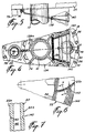
- Fig. 5 is a horizontal cross-section taken along lines 5-5 of Fig. 4;
- Fig. 6 is an enlarged fragmentary side elevation of a detail of the present invention;
- Fig. 7 is an enlarged fragmentary vertical cross-section taken along lines 7-7 of Fig. 6;
- Fig. 8 is an enlarged fragmentary cross-section of a detail shown in Fig.1.;
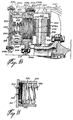
- Fig. 9 is an enlarged fragmentary front elevation of the brake assembly with parts removed to view further details of the present invention;
- Fig. 10 is a fragmentary axial section of another embodiment of a detail of the present invention;
- Fig. 11 is an enlarged fragmentary axial section showing still another embodiment of the detail shown in Fig.10;
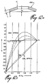
- Fig. 12a is a schematic view of a spring disc which can be used in an embodiment of the present invention; and
- Fig. 12b is a graph showing relative spring load characteristics of the spring disc.
-
- Referring to Figs. 1 to 3 the wheel assembly is shown with an
axle 10.Axle 10 is a dead axle andbearings 14 mount thewheel 12 for rotation thereabout. Anadapter sleeve 16 is mounted to thewheel 12 and extends concentrically over theaxle 10 within thedisc brake housing 18. A mountingring 20 is fixed to theaxle 10 and thehousing 18 is mounted to the mountingring 20. Two radial ventedrotor discs housing 18. Thehousing 18 includes anannular housing wall 26 on the inboard side of the assembly, anannular housing wall 28 on the outboard side, and the whole is surrounded by aperipheral wall 30.Ventilation openings 32 are provided in theperipheral wall 30. Nut andbolt arrangements 34 secure thehousing walls intermediate wall 62 together to form thehousing 18. - The
adapter sleeve 16 hasaxial splines 44 and the annularrotor brake discs disc openings teeth teeth splines 44, thereby providing limited axial movement to thediscs wheel 12. - Each
brake disc radial vent channels 46. It has been found that it is possible to maintain brake discs having vented channels within reasonable axial dimensions or thickness, by making the discs out of a composite of aluminum called "DURALCAN". Thus, it is possible to provide two or more brake discs in a space where only one vented cast iron brake disc was previously possible. Theopenings discs annular air deflector 48 is provided onadapter sleeve 16 in the plane of thehousing wall 28. - The
brake shoe 50 includes anannular backing plate 52 axially movable within thehousing 18 to which is mounted abrake lining 54. Thebacking plate 52,brake lining 54, andannular brake lining 56 are provided with peripheral slots and teeth which engage betweenbolts 34 of the housing to restrain them from rotation but to allow them to slide axially. Thebrake lining 54 is adapted to frictionally engage the planar radial disc surface 22A.Annular brake lining 56 is provided between thediscs annular brake lining 58 is mounted to thehousing wall 28. - Annular spacing rings 152 are provided in the
housing wall 30 and on the removal of the spacing rings 152 the housing will be reduced in axial dimension, thereby compensating for the wear on thelinings disc - An
intermediate wall 62 is mounted to the mountingring 20 on theaxle 10 by means of bolt andnut arrangements 71. Of course theintermediate wall 62 may be welded to mountingring 20. Theintermediate wall 62 also serves to support thehousing wall 26,cylindrical wall 30, andhousing wall 28 by means of the nut andbolt arrangements Ventilation channels 64 are provided in theintermediate wall 62 whileaxial ventilation openings 148 are provided in spaced apart relationship near the inner opening of the annularintermediate wall 62. - In the present embodiment a
plate 66 is placed against theintermediate wall 62 and is bolted thereto by means of nut andbolt arrangements plate 66 acts to support thebladder 68.Bladder 68 is an annular bladder made of stainless steel sheets, welded together as shown in Fig. 2. Air under pressure is fed to thebladder 68 through thetube 106 and inlet 108. Other gases may also be used to inflate the bladder. Stoppers (not shown) may be provided on theplate 66 adjacent thebladder 68 to prevent thebladder 68 from being crushed accidentally. - The
spring abutment member 92 is mounted for axial movements relative to theintermediate wall 62. Thespring abutment member 92 is in the form of a spider withlegs 94 spaced about the periphery of anannular plate 92A and integral therewith. Thelegs 94 extend throughopenings 72 in theintermediate wall 62.Seals 94A are provided in theopenings 72 surrounding thelegs 94 in order to prevent dust, oil or other debris from entering anyfurther into the housing. Thelegs 94 engage thebacking plate 52 near the peripheral edge thereof. In view of the stresses on the peripheral edge of thebacking plate 52, thebacking plate 52 may be constructed with a slight flare in the direction of the legs to compensate for the stresses which would apply when thelegs 94 come into contact at the peripheral edge of thebacking plate 52. The ends oflegs 94 might also be provided with a slight beveled angle to compensate for such stresses. -
Springs 90 urge thespring abutment plate 92 towards thebrake shoe 50. A plurality ofsprings 90 are provided in annular spaced apart locations on thehousing wall 26, each within abell cover 78 fitted within arespective opening 76 on thewall 26. The bell covers 78, in one embodiment have a rotary bayonet type of connection to engage thehousing wall 26 so that they can be removed in order to replace thesprings 90 for instance. Anut 80 having aflange 82 is provided exteriorly of thebell cover 78. Thenut 80 engages the threads ofbolt 84. The head of thebolt 84 is in ablind sleeve 86 which has a flange 88 and which abuts thecoil spring 90. Thus, if it is necessary to remove the tension of thesprings 90 against thespring abutment plate 92 thenut 80 is rotated to point where the head of thebolt 84 moves theblind sleeve 86 towards the left in Fig. 1 thereby releasing thespring 90 from thespring abutment member 92. Thenut 80 has arivet shoulder 80A to retain the nut to thebell cover 78. Although acoil spring 90 is shown, other types of springs such as an annular disc spring may be used. - To provide a service brake, a
bladder 70 is contemplated between theintermediate wall 62 and thebacking plate 52 ofbrake shoe 50. Thebladder 70 may be supplied with a gaseous fluid under pressure by an inlet similar to inlet 108 andtube 106. - During an emergency or parking brake mode, the
springs 90 urge against thespring abutment plate 92 which in turn presses thelegs 94 against thebacking plate 52 of thebrake shoe 50 to press thebrake linings brake discs - In other words, when the parking brakes or service brakes are applied, the pressure from the
brake shoe assembly 50 moves thedisc 22,brake lining 56 anddisc 24 axially such that the friction surfaces 22a,b, 24a,b ondiscs brake linings - Thus, the
springs 90 provide a safety brake, for the vehicle which would typically be a truck, tractor, or trailer. Once the truck or tractor is in operation, and the safety brakes are to be released, air pressure would be supplied to thebladder 68 by means oftube 106 and inlet 108, thereby expanding thebladder 68 to move thespring abutment member 92 axially to overcome thesprings 90 and thus removing the pressure on thebrake shoe 50, thereby allowing thediscs bladder 70 in order to move thebrake shoe 50 axially to positively apply the brakes. At the same time, air pressure could be released from thebladder 68, if necessary, although it is contemplated that the safety brakes would normally be kept released during operation. - As a safety feature, if the air pressure was to fall under a predetermined level, the
springs 90 would overcome thebladder 68 and cause the safety brakes to be applied. - A
quick release valve 126 is located on theintermediate wall 62 and communicates with thebladder 70. Thequick release valve 126 will operate when it is required to deflate thebladder 70. At the same time the exhaust from the quick release valve will be directed along theintermediate wall 62 throughventilation channels 64 thereby enabling theintermediate wall 62 to be cooled as well as the adjoining parts of the housing such asplate 66. The gas under pressure within thebladder 70 cools during decompression as it is released. - On the other hand a choke or restricted
passage 106A is provided on theconduit 106 to provide a slow release from thebladder 68 in order to avoid sudden violent application of the safety brakes while the vehicle is moving if a service brake malfunction should occur. A time delay valve might also be provided instead of the choke. - It has been contemplated to interconnect the
bladders bladders - The end edge of the
sleeve 16 may be provided with teeth and an antilock-brake sensor orcounter sensor 150 may be mounted to theintermediate wail 62 as shown in Fig. 1 for the purpose of sensing the movement of theteeth 151 as theadapter sleeve 16 rotates. - As shown in Fig. 2 the brake assembly is provided with a
thermal sensor 102 connected to theintermediate wall 62 and having alead 104. A thermal sensor 100 may be provided on thehousing wall 28 with a lead 105 extending through apassage 96 provided for in thehousing wall 30. Thethermal sensors 100 and 102 can provide temperature data with respect to the heat generated in the disc brake assembly, particularly near the disc. For instance the sensor 100 is right at thehousing wall 28 next to thebrake lining 58 near thedisc 24. Thethermal sensor 102 will indicate the temperature of theintermediate wall 62. Other sensors may be provided. Thesensors 100 and 102 communicate with a temperature indicator on the control panel in the vehicle. Only one wheel may need be monitored in such a manner as it will give an indication of the type of heat generated in all the wheels of the same vehicle. - A warning device, connected to the brake thermal sensors, may be provided on the control panel in the cab. The warning device may be an audible signal such as a buzzer or a recorded voice, or a visual diode graphic screen with different colours to provide information on the temperature of the brakes. As is well known when the temperature of the brakes reaches a certain temperature, the brake pads begin to break down chemically, causing brake fading. The warning device could alert the operator to stop the vehicle in order to allow the brakes to cool down before the brakes reach a temperature level that might cause failure.
- Another feature provided in the brake assembly described herein is a wear sensor as shown in Figs. 2 and 3. Because of the particular axial movement of the present brake assembly a wear sensor can be provided between the
housing wall 26 and thespring abutment member 92 and the distance between the two elements measured, particularly when the brakes are applied through the parking brakes under the urging ofsprings 90. - In one embodiment as shown in Fig. 2 the
wear sensor 112 includes arubber cap 114 and aplunger 116 urged by aspring 118 within a blind sleeve 120. Abearing sleeve 122 is provided within the sleeve 120 to allow the plunger to slide towards thespring abutment member 92 under the urging of thespring 118. The plunger is provided with a flange 124 to receive thespring 118. - Another form of wear sensor is shown in Fig. 3.
Wear sensor 130 is an electronic sensor including aplunger 132, spring mounted within thesensor 130, and urged against thespring abutment member 92.Sensor 130 communicates with a brake wear indicator on the control panel in the cab. Only one wheel need be monitored as it give a reliable indicator of the amount of wear occurring at all the wheels of a vehicle. - A still further wear sensor could be provided by allowing an opening in the
housing wall 26, closed by a rubber nipple 110. When the rubber nipple is removed a measuring gauge can be inserted to determine the distance between thewall 26 and thespring abutment member 92 when the parking brake is applied. - It is also contemplated to provide the brake sensors on the
housing wall 28 so that the measurements can be taken against a backing plate associated withbrake shoe 58 when the latter is made to move axially and thebladder 70 is mounted on the wall 28 (not shown). The service brake must be applied in order to take a proper reading. - With the use of the brake wear sensors or gauges a warning device can be provided on the control panel in the cab of the vehicle which would include an audible signal such as a buzzer when the brake linings and discs have been worn to a predetermined level to at least warn the operator to replace the brake linings and discs or at least plan the maintenance thereof. It may even be contemplated to provide an interlock which would intervene at the parking brake control valve to impede the release of the parking brakes when the brake wear has exceeded accepted levels of wear. In any event the brake wear system can give warning or control at different levels of brake wear.
- A ventilation system for the disc brakes is provided. As partially, previously described and shown in Figs. 1 and 9,
openings 148 are located in theintermediate wall 62 and as shown in Fig. 4 aplenum 134, in the form of an annular cover, may be placed over theopenings 148. Theplenum 134 communicates with ascoop 136. Thescoop 136 may be mounted on thehousing wall 26 and would be facing the normal direction of travel of the vehicle so that air flow would be deflected into theplenum 134, through theopenings 148 to thediscs openings ventilation channels 46 of thediscs baffle 48 could be eliminated if thedisc 24 is closed to theadapter sleeve 16. Thediscs openings ventilation openings 32 allowing a great amount of heat to be dissipated in this way. Thescoop 136 and theplenum 134 may be a molded plastic member with ahinge 138 molded therein along with nut andbolt adjustments 140 to open or reduce the opening of thescoop 136. - It has been contemplated to use this ventilation system for a different purpose, such as in an aircraft utilization. Accordingly, by providing a similar brake configuration on the wheels of the landing gear of an aircraft, that is with
scoop 136,ventilation openings 32 and ventilateddiscs scoop 136 may be remotely adjusted and the active brakes could be applied. The wheel speed may be calibrated to the ground speed of the aircraft using a microprocessor using information from thecounter sensor 150 and the aircraft ground speed data. The precise rate of rotation could be achieved by having the microprocessor modulate the scoop opening and the brakes to compensate for the excess of torque generated by the air flow through the brakes. This would be an important safety factor with respect to aircraft tires. - A fragment of a
brake disc 22 is shown in Figs. 6 and 7 with the surfaces 22A and 22B illustrated. Agroove 142 extends somewhat radially of the surfaces 22A and 22B and has a semi-circular cross-section. In a specific example, the groove may be 0.09" in depth with a width of 0.25" and a radius of 1/8 of an inch. It has been found that the provision of such a groove allows air to enter, when the brakes are released and the discs are rotating, to form a slight air cushion between the brake linings and the friction surface on the disc, thereby eliminating dragging and helping to cool the friction surfaces. At the same time the groove allows the brake surfaces to be cleaned by providing a drainage channel for any liquid forming on the brake linings or debris between the friction surface of the disc and the linings. - It has also been found that by providing a coating on the disc brake surface the heat is more easily dissipated. This coating may be a ceramic with aluminum particulates mixed therein and which has a particular heat sink and wear resistance properties. The coating may also be titanium carbo-nitride or chromium carbide. A coating is presently being developed by "SERMATECH INTERNATIONAL INC." for military purposes.
- It has also been contemplated to provide a spray mix where water is sprayed into the
plenum 134 throughopening 134a to mix with ventilation air being deflected into the brake assembly to enhance the cooling of the brake assembly. - In the present embodiment, and as shown in Fig. 8, the
bladder 70, which is in the form of an annular ring, is provided with an externalannular dust cap 70a and aninternal dust cap 70b. The dust caps 70a and 70b are provided to prevent debris from entering between the accordion like fins formed in the bellows-like bladder. - In the embodiment shown in Fig. 10, the
bladder 290 adjusts the distance between lining 273 andfriction surface 232a ofdisc 232, as will be described. In this embodiment,plate 223 is provided with integral posts 223a, which slide inbushings 266 mounted to the circumferential wall 226. Thebushings 266 prevent posts 223a from jamming and thus plate 262 to slide parallel tointermediate wall 244. These posts 223a engage against themovable plate 262.Posts 264 extend fromplate 262 to engage thebacking plate 272. - A
bladder 290 is provided betweenplate 223 and housing wall 222 which is bolted to thehousing walls 226 and 248, as shown. Thebladder 290 may be oil or grease filled. In either case, the increase of the volume in thebladder 290 will tend to distance theplate 223 from the wall 222, thereby moving the parking brakeassembly including spring 256,spring abutment plate 262,posts 264, backingplate 272, and lining 273 closer to thedisc 232. When the posts 223a have engaged theplate 262, thebladder 290 is used to compensate for brake disc or lining wear by pressing theplate 223 and posts 223a against the cage formed byplate 262 and posts 264. - As shown in Fig. 10, the
bladders bladder 284 andbladder 282 is deflated, or to remove the brakes against the force ofspring 256 by increasing the air pressure inbladder 282 and deflatingbladder 284. - It is also contemplated that the
bladders housing walls brake linings - Instead of the
bladder 290, the compensation for brake wear could be provided by the compensating ring 229. Ring 229 is a segmental ring which can easily be removed from betweenintermediate wall 244 and flange 226b of housing wall 226. A compensating ring (not shown) may be provided betweenintermediate wall 244 andflanges 248b and 226a. The compensating ring 229 could also be placed between the housing wall 222 and the mountingflange 226c therefor. A compensating ring (not shown) would then be mounted between wall 222 and flange 248a. The idea is to allow for a decrease of the axial length of thehousing 216 in order to compensate for wear of all parts of the braking system. - Fig. 11 shows an embodiment of the device for adjusting the spring length to increase the force against the brake shoes or for compensating for brake wear. In the embodiment shown, a
grease nipple 392 incap 361 can be utilized to insert grease or oil into thecavity 390 to displace thewall 355 incylinder 354. When it is required to release thespring 356, theplug 393 can be released to allow the grease or oil to exit, thereby allowing thewall 355 to slide towards thecap 361. - In another embodiment, disc springs 490 could be used instead of coil springs 90,256,356. A single disc spring is illustrated in Fig. 12a and the characteristics thereof are shown in Fig. 12b. For a more ample description of the disc spring reference is made to the "Schnorr Handbook for Disc Springs" published 1983 by Adolf Schnorr GmbH & Co. KG, P.O. Box 60, D-7032 Sindelfingen 6, Germany. It has been found that by stacking disc springs in different configurations, different spring rates can be obtained.
- One characteristic of the disc spring which is particularly useful in the present invention is that the full deflection spring load characteristic does not decrease until a large percentage of the spring deflection has occurred, i.e. approximately 50% to 70% when ho/t is larger than 1.6 and smaller than 2.0. The distance represented by the travel within these limits may represent the compensation for wear. With other spring characteristics the same travel, i.e. 50% to 70% would result in a significant reduction in the spring load characteristic as shown in Fig. 12b where
- ho
- represents the formed height of an unloaded single disc in mm;
- t
- represents the thickness of a single disc spring in mm;
- S
- is the deflection in mm;
- K
- = F/Fc;
- F
- is the spring load;
- Fc
- is the calculated load given by a single disc pressed flat.
- It should be understood that the various embodiments of the invention are not only covered by any of the following claims but also by any combination of these claims.
Claims (10)
- A disc brake assembly for a vehicle wheel (12) on a vehicle wherein the wheel (12) includes a hub journaled (14) to an axle (10) on the vehicle, the disc brake assembly is within the confines of the wheel (12) and concentric with the axle (10), the disc brake assembly including a housing (18) mounted to the vehicle and at least a radial disc (22, 24) within the housing (18), and means (16) mounting the disc (22, 24) to the wheel (12) the disc (22, 24) having at least a first radial planar friction surface (22a) and a first brake shoe (50) provided adjacent the first planar friction surface (22a) movable axially towards and away from the first friction surface (22a) of the disc (22, 24) for friction engagement therewith and release thereof, an intermediate wall member (62) mounted within the housing (18) and fixed thereto and extending parallel with the radial disc (22,24) and located such that the first brake shoe (50) moves axially between the intermediate wall (62) and the radial disc (22, 24), means provided for restraining the first brake shoe from rotating with the disc (22, 24), movable spring abutment means (92) mounted for axial movement within the housing (18) between the intermediate wall (62) and a housing wall (26) such that the intermediate wall (62) is between the movable spring abutment means (92) and the first brake shoe (50), rigid pusher link members (94) extending between the spring abutment means (92) and the first brake shoe (50) and passing by the intermediate wall 62) such that the first brake shoe (50) moves axially with the spring abutment means (92), a spring means (90) extending between the housing wall (26) and the spring abutment means (92) such that the spring means (90) urges against the spring abutment means (92) to press the first brake shoe (50) against the first friction surface (22a) of the disc (22, 24) in a parking brake mode, the brake shoe (50) including linings (54) to engage the first planar friction surface (22a) of the disc (22, 24) and wear gauge means (110,112,130) adapted to the housing wall (26) such that the distance between the housing wall (26) and the spring abutment means (92) can be monitored when in the parking brake mode, to determine the wear of the linings (54,56,58) and disc (22,24) of the brake assembly.
- A brake assembly as defined in claim 1, wherein the wear gauge means (110,112,130) is in the form of an aperture provided in the housing wall (26) to allow a measuring gauge to be passed therethrough.
- A brake assembly as defined in claim 1, wherein the brake wear gauge means (110, 112, 130) includes a spring mounted plunger means (116) provided on the housing wall (26) and wherein the spring (118) urges the plunger (116) against the spring abutment means (92) and a portion of the plunger extends beyond the housing wall (26) whereby the brake wear will be gauged by determining the amount of protrusion of the plunger (116) exterior of the housing wall.
- A brake assembly as defined in claim 1, wherein the brake wear gauge means (110, 112, 130) is in the form of an electronic measuring device (130) in association with a plunger (132) urging against the spring abutment means (92) to determine the distance between the housing wall (26) and the spring abutment means (92) and means for communicating the results to a display means.
- A disc brake assembly for a vehicle wheel (12) on a vehicle wherein the wheel (12) includes a hub journaled (14) to an axle (10) on the vehicle, the disc brake assembly is within the confines of the wheels (12) and includes a housing (18) mounted to the vehicle, housing (18) including at least a housing wall (28) and at least a radial disc (22, 24) within the housing (18) and means (16, 44) mounting the disc (22, 24) to the wheel (12), the radial disc (22, 24) having at least a first radial planar friction surface (22a,b, 24a,b) and a first brake shoe means (50, 58) provided adjacent the first planar friction surface (22a,b...) of the disc (22, 24) movable axially towards and away from the first friction surface (22a,b ...) of the disc (22, 24) for friction engagement therewith and release thereof, means provided for restraining the first brake shoe means (5O, 58) from rotating with the disc (22, 24), means for axially moving the first brake shoe means away from the housing wall (28) to engage the first friction surface (22a,b...) of the disc (22, 24), wear gauge means (110,112,130) adapted to the housing wall (28) and the first brake shoe means such that the distance between the housing wall (28) and the first brake shoe means (50, 58) can be monitored when the brakes are applied, to determine the wear of the lining and of the disc of the brake assembly.
- A brake assembly as defined in claim 5, wherein the wear gauge means (110,112,130) is in the form of an aperture provided in the housing wall (28) to allow a measuring gauge to be passed there through.
- A brake assembly as defined in claim 5, wherein the brake wear gauge means (110,112,130) includes a spring mounted plunger means (116) provided on the housing wall (28) and wherein the spring (118) urges the plunger (116) against the first brake shoe means (50, 58) and a portion of the plunger (116) extends beyond the housing wall (28) whereby the brake wear will be gauged by determining the amount of protrusion of the plunger (116) exterior of the housing wall (28).
- A brake assembly as defined in claim 5, wherein the brake wear gauge means (11O,112,130) is in the form of an electronic measuring device (130) in association with a plunger (132) urging against the first brake shoe means (50, 58) to determine the distance between the housing wall (28) and the first brake shoe means (50, 58) and means for communicating the results to a display means.
- A brake assembly as defined in claims 4 or 8, wherein a warning device means is provided on a vehicle to warn the operator that the brake lining (54, 56, 58) and disc (22, 24) are worn to a predeterminated level.
- A brake assembly as defined in claims 4 or 8, wherein an interlock means is provided and will intervene the parking brake control means when the lining (54, 56, 58) and disc (22, 24) have exceeded a predeterminated level of wear.
Applications Claiming Priority (6)
| Application Number | Priority Date | Filing Date | Title |
|---|---|---|---|
| US07/719,130 US5205380A (en) | 1990-07-13 | 1991-06-20 | Disc brake assembly |
| US86141992A | 1992-03-31 | 1992-03-31 | |
| US861419 | 1992-03-31 | ||
| EP97110121A EP0801246B1 (en) | 1991-06-20 | 1992-06-22 | Brake assembly |
| EP92913381A EP0588926B1 (en) | 1991-06-20 | 1992-06-22 | Brake assembly |
| US719130 | 1996-09-24 |
Related Parent Applications (1)
| Application Number | Title | Priority Date | Filing Date |
|---|---|---|---|
| EP97110121A Division EP0801246B1 (en) | 1991-06-20 | 1992-06-22 | Brake assembly |
Publications (3)
| Publication Number | Publication Date |
|---|---|
| EP1081404A2 true EP1081404A2 (en) | 2001-03-07 |
| EP1081404A3 EP1081404A3 (en) | 2001-04-18 |
| EP1081404B1 EP1081404B1 (en) | 2005-05-11 |
Family
ID=27110032
Family Applications (3)
| Application Number | Title | Priority Date | Filing Date |
|---|---|---|---|
| EP97110121A Expired - Lifetime EP0801246B1 (en) | 1991-06-20 | 1992-06-22 | Brake assembly |
| EP92913381A Expired - Lifetime EP0588926B1 (en) | 1991-06-20 | 1992-06-22 | Brake assembly |
| EP00124308A Expired - Lifetime EP1081404B1 (en) | 1991-06-20 | 1992-06-22 | Brake assembly |
Family Applications Before (2)
| Application Number | Title | Priority Date | Filing Date |
|---|---|---|---|
| EP97110121A Expired - Lifetime EP0801246B1 (en) | 1991-06-20 | 1992-06-22 | Brake assembly |
| EP92913381A Expired - Lifetime EP0588926B1 (en) | 1991-06-20 | 1992-06-22 | Brake assembly |
Country Status (10)
| Country | Link |
|---|---|
| EP (3) | EP0801246B1 (en) |
| AT (3) | ATE173527T1 (en) |
| AU (1) | AU2181392A (en) |
| CA (1) | CA2110996C (en) |
| DE (3) | DE69227629T2 (en) |
| DK (1) | DK0588926T3 (en) |
| ES (2) | ES2167643T3 (en) |
| GR (1) | GR3029430T3 (en) |
| RU (1) | RU2126503C1 (en) |
| WO (1) | WO1993000525A2 (en) |
Cited By (1)
| Publication number | Priority date | Publication date | Assignee | Title |
|---|---|---|---|---|
| WO2002101259A1 (en) * | 2001-06-13 | 2002-12-19 | Freni Brembo S.P.A. | A disk-brake disk with air cooling |
Families Citing this family (15)
| Publication number | Priority date | Publication date | Assignee | Title |
|---|---|---|---|---|
| ES1035357Y (en) * | 1995-06-15 | 1998-07-01 | Mellado Tomas Ismael | C.T.F. CONTROL OF BRAKE TEMPERATURE IN HEAVY VEHICLES. |
| EP1350979A3 (en) * | 1996-12-31 | 2004-01-07 | RANCOURT, Yvon | Improved disc brake assembly |
| US6003640A (en) | 1997-05-09 | 1999-12-21 | The B.F. Goodrich Company | Electronic braking system with brake wear measurement and running clearance adjustment |
| DE19724117A1 (en) * | 1997-06-09 | 1998-12-10 | Zf Luftfahrttechnik Gmbh | Brake for a lift flap adjustment mechanism |
| EP1409885A1 (en) * | 2001-02-21 | 2004-04-21 | Group Newtech International Inc. | Brake wear compensator |
| WO2006047887A1 (en) * | 2004-11-04 | 2006-05-11 | Groupe Newtech International Inc. | Rotor disk support for a full contact annular disk brake assembly |
| US20080092641A1 (en) * | 2006-10-18 | 2008-04-24 | Goodrich Corporation | Wear compensated torque measurement system |
| DE202006017481U1 (en) * | 2006-11-16 | 2007-12-27 | Niles-Simmons Industrieanlagen Gmbh | Device for clamping waves |
| RU2495792C2 (en) * | 2011-07-11 | 2013-10-20 | Сергей Иванович Ивандаев | Method of aircraft landing gear wheels driving and aircraft landing gear with driven wheels |
| RU2522643C2 (en) * | 2012-07-25 | 2014-07-20 | Российская Федерация, От Имени Которой Выступает Министерство Промышленности И Торговли Российской Федерации | Electromechanical drive unit for aircraft main landing gear wheel disc brake |
| CA2886962A1 (en) | 2012-09-24 | 2014-03-27 | Sergey Ivanovich IVANDAEV | Methods of the airplane's landing gear drive and landing gear construction |
| CN106151052B (en) * | 2016-08-26 | 2018-12-28 | 韩全伟 | Surface drive with hydraulic, speed limit, temperature control reverse-rotation preventing function |
| RU190192U1 (en) * | 2019-03-05 | 2019-06-24 | Публичное акционерное общество "Авиационная корпорация "Рубин" | BRAKE WHEEL WITH HYDRAULIC BRAKE, CARBON - CARBON MONODISKS AND AIR COOLING |
| AU2020371497A1 (en) * | 2019-10-23 | 2022-04-07 | Dexter Axle Company, LLC | Wheel sensors within vehicular brake assemblies |
| CN115163705B (en) * | 2022-08-01 | 2023-08-25 | 句容市天王汽车配件制造有限公司 | Lightweight brake disc and brake disc manufacturing process |
Citations (4)
| Publication number | Priority date | Publication date | Assignee | Title |
|---|---|---|---|---|
| US2547234A (en) | 1948-07-16 | 1951-04-03 | Cube Steak Machine Co | Meat tenderizing machine |
| US4057297A (en) | 1976-06-28 | 1977-11-08 | Beck Henry E | Brake mechanism with spring applied fluid pressure released assembly |
| US4102438A (en) | 1976-10-18 | 1978-07-25 | The Dolphin Brake Corp. | Disc brake assembly |
| CA1140486A (en) | 1976-10-18 | 1983-02-01 | Yvon Rancourt | Braking disc for disc brake assembly |
Family Cites Families (21)
| Publication number | Priority date | Publication date | Assignee | Title |
|---|---|---|---|---|
| US2248684A (en) * | 1938-03-29 | 1941-07-08 | Siam | Wheel for airplane undercarriages or other heavy vehicles |
| US2412884A (en) * | 1945-12-28 | 1946-12-17 | Peter J Grabash | Airplane wheel turning device |
| US2552571A (en) * | 1946-06-01 | 1951-05-15 | Mercier Pierre Ernest | Aircraft brake cooling means |
| GB639558A (en) * | 1947-03-29 | 1950-06-28 | Dunlop Rubber Co | Improvements in or relating to disc brakes |
| GB677248A (en) * | 1949-06-24 | 1952-08-13 | Dunlop Rubber Co | An improved wheel and brake assembly |
| US2822997A (en) * | 1953-12-17 | 1958-02-11 | Bendix Aviat Corp | Fairing scoop for aircraft wheel |
| US3096649A (en) * | 1959-12-14 | 1963-07-09 | Bendix Corp | Brake overtemperature detector and indicator |
| DE1555186A1 (en) * | 1966-12-23 | 1970-07-02 | Daimler Benz Ag | Air-cooled disc brakes for vehicles, especially for motor vehicles |
| FR1521872A (en) * | 1967-05-03 | 1968-04-19 | Fawick Corp | Brake or clutch device and friction element therefor |
| US3547234A (en) * | 1969-02-14 | 1970-12-15 | Caterpillar Tractor Co | Dual range brake system for vehicles |
| GB1410330A (en) * | 1972-02-28 | 1975-10-15 | Girling Ltd | Spring brake actuators for disc brakes |
| US3999634A (en) * | 1974-01-14 | 1976-12-28 | Howell Industries, Inc. | Pneumatic actuation for disc brake assemblies |
| US3946837A (en) * | 1974-12-26 | 1976-03-30 | Rohr Industries, Inc. | Disc brake and actuator assembly |
| DE7729939U1 (en) * | 1977-09-27 | 1978-03-02 | International Harvester Company Mbh, 4040 Neuss | DEVICE FOR CHECKING BRAKE PAD WEAR ON VEHICLE BRAKES, IN PARTICULAR DISC BRAKES |
| US4186822A (en) * | 1978-06-28 | 1980-02-05 | General Motors Corporation | Disc brake pack wear indicator |
| EP0038370A1 (en) * | 1980-04-18 | 1981-10-28 | Binder Magnete GmbH | Fluid-pressure operated disc clutch or disc brake |
| US4658936A (en) * | 1985-07-25 | 1987-04-21 | Goodyear Aerospace Corporation | Brake temperature and wear indicator |
| DE3606876C2 (en) * | 1986-03-03 | 1996-07-18 | Pulsgetriebe Dipl Ingenieure W | Wheel hub gear |
| US4815572A (en) * | 1987-07-24 | 1989-03-28 | Parker-Hannifin Corporation | Brake system with improved brake material |
| DE3815994A1 (en) * | 1988-05-10 | 1989-11-23 | Daimler Benz Ag | METHOD FOR TESTING THE TIGHTNESS OF SEALING ELEMENTS IN SHUT-OFF ARMATURES AND DEVICE FOR IMPLEMENTING THE METHOD |
| JP2987704B2 (en) * | 1988-07-15 | 1999-12-06 | 財団法人鉄道総合技術研究所 | Brake disc material for high-speed railway vehicles |
-
1992
- 1992-06-22 AT AT92913381T patent/ATE173527T1/en not_active IP Right Cessation
- 1992-06-22 RU RU93058604A patent/RU2126503C1/en not_active IP Right Cessation
- 1992-06-22 DE DE69227629T patent/DE69227629T2/en not_active Expired - Fee Related
- 1992-06-22 DE DE69232157T patent/DE69232157T2/en not_active Expired - Fee Related
- 1992-06-22 EP EP97110121A patent/EP0801246B1/en not_active Expired - Lifetime
- 1992-06-22 AT AT00124308T patent/ATE295490T1/en not_active IP Right Cessation
- 1992-06-22 AU AU21813/92A patent/AU2181392A/en not_active Abandoned
- 1992-06-22 ES ES97110121T patent/ES2167643T3/en not_active Expired - Lifetime
- 1992-06-22 ES ES92913381T patent/ES2127218T3/en not_active Expired - Lifetime
- 1992-06-22 DE DE69233511T patent/DE69233511T2/en not_active Expired - Fee Related
- 1992-06-22 EP EP92913381A patent/EP0588926B1/en not_active Expired - Lifetime
- 1992-06-22 DK DK92913381T patent/DK0588926T3/en active
- 1992-06-22 EP EP00124308A patent/EP1081404B1/en not_active Expired - Lifetime
- 1992-06-22 AT AT97110121T patent/ATE207581T1/en active
- 1992-06-22 CA CA002110996A patent/CA2110996C/en not_active Expired - Fee Related
- 1992-06-22 WO PCT/CA1992/000266 patent/WO1993000525A2/en active IP Right Grant
-
1999
- 1999-02-17 GR GR990400513T patent/GR3029430T3/en unknown
Patent Citations (5)
| Publication number | Priority date | Publication date | Assignee | Title |
|---|---|---|---|---|
| US2547234A (en) | 1948-07-16 | 1951-04-03 | Cube Steak Machine Co | Meat tenderizing machine |
| US4057297A (en) | 1976-06-28 | 1977-11-08 | Beck Henry E | Brake mechanism with spring applied fluid pressure released assembly |
| US4102438A (en) | 1976-10-18 | 1978-07-25 | The Dolphin Brake Corp. | Disc brake assembly |
| CA1112189A (en) | 1976-10-18 | 1981-11-10 | Yvon Rancourt | Disc brake assembly |
| CA1140486A (en) | 1976-10-18 | 1983-02-01 | Yvon Rancourt | Braking disc for disc brake assembly |
Cited By (1)
| Publication number | Priority date | Publication date | Assignee | Title |
|---|---|---|---|---|
| WO2002101259A1 (en) * | 2001-06-13 | 2002-12-19 | Freni Brembo S.P.A. | A disk-brake disk with air cooling |
Also Published As
| Publication number | Publication date |
|---|---|
| ATE207581T1 (en) | 2001-11-15 |
| EP0801246A3 (en) | 1998-11-18 |
| CA2110996C (en) | 2003-10-14 |
| DK0588926T3 (en) | 1999-06-23 |
| DE69233511T2 (en) | 2006-02-02 |
| DE69232157T2 (en) | 2002-07-04 |
| AU2181392A (en) | 1993-01-25 |
| EP0801246B1 (en) | 2001-10-24 |
| CA2110996A1 (en) | 1993-01-07 |
| ES2167643T3 (en) | 2002-05-16 |
| ATE173527T1 (en) | 1998-12-15 |
| ES2127218T3 (en) | 1999-04-16 |
| DE69232157D1 (en) | 2001-11-29 |
| EP0801246A2 (en) | 1997-10-15 |
| WO1993000525A2 (en) | 1993-01-07 |
| EP0588926A1 (en) | 1994-03-30 |
| RU2126503C1 (en) | 1999-02-20 |
| EP1081404B1 (en) | 2005-05-11 |
| ATE295490T1 (en) | 2005-05-15 |
| DE69233511D1 (en) | 2005-06-16 |
| EP0588926B1 (en) | 1998-11-18 |
| EP1081404A3 (en) | 2001-04-18 |
| DE69227629T2 (en) | 1999-09-09 |
| GR3029430T3 (en) | 1999-05-28 |
| WO1993000525A3 (en) | 1993-03-04 |
| DE69227629D1 (en) | 1998-12-24 |
Similar Documents
| Publication | Publication Date | Title |
|---|---|---|
| US5651430A (en) | Disc brake assembly | |
| US5330034A (en) | Brake assembly | |
| EP0588926B1 (en) | Brake assembly | |
| CA1056742A (en) | Annular single piston brake arrangement | |
| CA2046370C (en) | Disc brake assembly | |
| US3931871A (en) | Disc brake, hub and wheel assembly | |
| US5253737A (en) | Auxiliary brake force multiplying spring in a multidisc service and auxiliary brake system | |
| ZA200503844B (en) | Wheel hub. | |
| US20050252730A1 (en) | Wheel hub | |
| US6550588B2 (en) | Off highway truck brake assembly and wheel spindle having a spline joint | |
| US4845468A (en) | Brake condition warning system | |
| US3637053A (en) | Disc brake apparatus | |
| US5865277A (en) | Wheels and brakes for vehicles | |
| US5366046A (en) | Full-lining disk brake with heat dissipation features | |
| US3334946A (en) | Vehicle wheel and brake | |
| JP2010528920A (en) | Purge valve for mounting assembly | |
| GB2047365A (en) | Vehicle brakes | |
| WO2014176629A1 (en) | Disc brake system |
Legal Events
| Date | Code | Title | Description |
|---|---|---|---|
| PUAI | Public reference made under article 153(3) epc to a published international application that has entered the european phase |
Free format text: ORIGINAL CODE: 0009012 |
|
| PUAL | Search report despatched |
Free format text: ORIGINAL CODE: 0009013 |
|
| AC | Divisional application: reference to earlier application |
Ref document number: 588926 Country of ref document: EP Ref document number: 801246 Country of ref document: EP |
|
| AK | Designated contracting states |
Kind code of ref document: A2 Designated state(s): AT BE CH DE DK ES FR GB GR IT LI LU MC NL SE |
|
| AK | Designated contracting states |
Kind code of ref document: A3 Designated state(s): AT BE CH DE DK ES FR GB GR IT LI LU MC NL SE |
|
| RIC1 | Information provided on ipc code assigned before grant |
Free format text: 7F 16D 55/36 A, 7F 16D 65/16 B, 7F 16D 65/12 B, 7F 16D 65/847 B, 7F 16D 66/00 B, 7F 16D 66/02 B, 7B 64C 25/40 B, 7F 16D 55/28 B |
|
| 17P | Request for examination filed |
Effective date: 20011018 |
|
| AKX | Designation fees paid |
Free format text: AT BE CH DE DK ES FR GB GR IT LI LU MC NL SE |
|
| 17Q | First examination report despatched |
Effective date: 20020701 |
|
| GRAP | Despatch of communication of intention to grant a patent |
Free format text: ORIGINAL CODE: EPIDOSNIGR1 |
|
| GRAS | Grant fee paid |
Free format text: ORIGINAL CODE: EPIDOSNIGR3 |
|
| GRAA | (expected) grant |
Free format text: ORIGINAL CODE: 0009210 |
|
| AC | Divisional application: reference to earlier application |
Ref document number: 0801246 Country of ref document: EP Kind code of ref document: P Ref document number: 0588926 Country of ref document: EP Kind code of ref document: P |
|
| AK | Designated contracting states |
Kind code of ref document: B1 Designated state(s): AT BE CH DE DK ES FR GB GR IT LI LU MC NL SE |
|
| PG25 | Lapsed in a contracting state [announced via postgrant information from national office to epo] |
Ref country code: IT Free format text: LAPSE BECAUSE OF FAILURE TO SUBMIT A TRANSLATION OF THE DESCRIPTION OR TO PAY THE FEE WITHIN THE PRESCRIBED TIME-LIMIT;WARNING: LAPSES OF ITALIAN PATENTS WITH EFFECTIVE DATE BEFORE 2007 MAY HAVE OCCURRED AT ANY TIME BEFORE 2007. THE CORRECT EFFECTIVE DATE MAY BE DIFFERENT FROM THE ONE RECORDED. Effective date: 20050511 Ref country code: AT Free format text: LAPSE BECAUSE OF FAILURE TO SUBMIT A TRANSLATION OF THE DESCRIPTION OR TO PAY THE FEE WITHIN THE PRESCRIBED TIME-LIMIT Effective date: 20050511 Ref country code: BE Free format text: LAPSE BECAUSE OF FAILURE TO SUBMIT A TRANSLATION OF THE DESCRIPTION OR TO PAY THE FEE WITHIN THE PRESCRIBED TIME-LIMIT Effective date: 20050511 Ref country code: NL Free format text: LAPSE BECAUSE OF FAILURE TO SUBMIT A TRANSLATION OF THE DESCRIPTION OR TO PAY THE FEE WITHIN THE PRESCRIBED TIME-LIMIT Effective date: 20050511 Ref country code: LI Free format text: LAPSE BECAUSE OF FAILURE TO SUBMIT A TRANSLATION OF THE DESCRIPTION OR TO PAY THE FEE WITHIN THE PRESCRIBED TIME-LIMIT Effective date: 20050511 Ref country code: CH Free format text: LAPSE BECAUSE OF FAILURE TO SUBMIT A TRANSLATION OF THE DESCRIPTION OR TO PAY THE FEE WITHIN THE PRESCRIBED TIME-LIMIT Effective date: 20050511 |
|
| REG | Reference to a national code |
Ref country code: GB Ref legal event code: FG4D |
|
| REG | Reference to a national code |
Ref country code: CH Ref legal event code: EP |
|
| REF | Corresponds to: |
Ref document number: 69233511 Country of ref document: DE Date of ref document: 20050616 Kind code of ref document: P |
|
| PG25 | Lapsed in a contracting state [announced via postgrant information from national office to epo] |
Ref country code: LU Free format text: LAPSE BECAUSE OF NON-PAYMENT OF DUE FEES Effective date: 20050622 |
|
| PG25 | Lapsed in a contracting state [announced via postgrant information from national office to epo] |
Ref country code: MC Free format text: LAPSE BECAUSE OF NON-PAYMENT OF DUE FEES Effective date: 20050630 |
|
| PGFP | Annual fee paid to national office [announced via postgrant information from national office to epo] |
Ref country code: GB Payment date: 20050810 Year of fee payment: 14 |
|
| PG25 | Lapsed in a contracting state [announced via postgrant information from national office to epo] |
Ref country code: DK Free format text: LAPSE BECAUSE OF FAILURE TO SUBMIT A TRANSLATION OF THE DESCRIPTION OR TO PAY THE FEE WITHIN THE PRESCRIBED TIME-LIMIT Effective date: 20050811 Ref country code: GR Free format text: LAPSE BECAUSE OF FAILURE TO SUBMIT A TRANSLATION OF THE DESCRIPTION OR TO PAY THE FEE WITHIN THE PRESCRIBED TIME-LIMIT Effective date: 20050811 |
|
| PG25 | Lapsed in a contracting state [announced via postgrant information from national office to epo] |
Ref country code: ES Free format text: LAPSE BECAUSE OF FAILURE TO SUBMIT A TRANSLATION OF THE DESCRIPTION OR TO PAY THE FEE WITHIN THE PRESCRIBED TIME-LIMIT Effective date: 20050822 |
|
| PGFP | Annual fee paid to national office [announced via postgrant information from national office to epo] |
Ref country code: SE Payment date: 20050823 Year of fee payment: 14 |
|
| REG | Reference to a national code |
Ref country code: SE Ref legal event code: TRGR |
|
| PGFP | Annual fee paid to national office [announced via postgrant information from national office to epo] |
Ref country code: DE Payment date: 20050825 Year of fee payment: 14 |
|
| NLV1 | Nl: lapsed or annulled due to failure to fulfill the requirements of art. 29p and 29m of the patents act | ||
| REG | Reference to a national code |
Ref country code: CH Ref legal event code: PL |
|
| PLBE | No opposition filed within time limit |
Free format text: ORIGINAL CODE: 0009261 |
|
| STAA | Information on the status of an ep patent application or granted ep patent |
Free format text: STATUS: NO OPPOSITION FILED WITHIN TIME LIMIT |
|
| ET | Fr: translation filed | ||
| 26N | No opposition filed |
Effective date: 20060214 |
|
| PG25 | Lapsed in a contracting state [announced via postgrant information from national office to epo] |
Ref country code: GB Free format text: LAPSE BECAUSE OF NON-PAYMENT OF DUE FEES Effective date: 20060622 |
|
| PG25 | Lapsed in a contracting state [announced via postgrant information from national office to epo] |
Ref country code: SE Free format text: LAPSE BECAUSE OF NON-PAYMENT OF DUE FEES Effective date: 20060623 |
|
| PG25 | Lapsed in a contracting state [announced via postgrant information from national office to epo] |
Ref country code: DE Free format text: LAPSE BECAUSE OF NON-PAYMENT OF DUE FEES Effective date: 20070103 |
|
| EUG | Se: european patent has lapsed | ||
| GBPC | Gb: european patent ceased through non-payment of renewal fee |
Effective date: 20060622 |
|
| PGFP | Annual fee paid to national office [announced via postgrant information from national office to epo] |
Ref country code: FR Payment date: 20070630 Year of fee payment: 16 |
|
| REG | Reference to a national code |
Ref country code: FR Ref legal event code: ST Effective date: 20111202 |
|
| PG25 | Lapsed in a contracting state [announced via postgrant information from national office to epo] |
Ref country code: FR Free format text: LAPSE BECAUSE OF NON-PAYMENT OF DUE FEES Effective date: 20060630 |