EP1081383A2 - Rotary compressor - Google Patents
Rotary compressor Download PDFInfo
- Publication number
- EP1081383A2 EP1081383A2 EP00307523A EP00307523A EP1081383A2 EP 1081383 A2 EP1081383 A2 EP 1081383A2 EP 00307523 A EP00307523 A EP 00307523A EP 00307523 A EP00307523 A EP 00307523A EP 1081383 A2 EP1081383 A2 EP 1081383A2
- Authority
- EP
- European Patent Office
- Prior art keywords
- shaft
- cross
- eccentric
- rotary
- compressor according
- Prior art date
- Legal status (The legal status is an assumption and is not a legal conclusion. Google has not performed a legal analysis and makes no representation as to the accuracy of the status listed.)
- Granted
Links
Images


Classifications
-
- F—MECHANICAL ENGINEERING; LIGHTING; HEATING; WEAPONS; BLASTING
- F04—POSITIVE - DISPLACEMENT MACHINES FOR LIQUIDS; PUMPS FOR LIQUIDS OR ELASTIC FLUIDS
- F04C—ROTARY-PISTON, OR OSCILLATING-PISTON, POSITIVE-DISPLACEMENT MACHINES FOR LIQUIDS; ROTARY-PISTON, OR OSCILLATING-PISTON, POSITIVE-DISPLACEMENT PUMPS
- F04C18/00—Rotary-piston pumps specially adapted for elastic fluids
- F04C18/30—Rotary-piston pumps specially adapted for elastic fluids having the characteristics covered by two or more of groups F04C18/02, F04C18/08, F04C18/22, F04C18/24, F04C18/48, or having the characteristics covered by one of these groups together with some other type of movement between co-operating members
- F04C18/34—Rotary-piston pumps specially adapted for elastic fluids having the characteristics covered by two or more of groups F04C18/02, F04C18/08, F04C18/22, F04C18/24, F04C18/48, or having the characteristics covered by one of these groups together with some other type of movement between co-operating members having the movement defined in group F04C18/08 or F04C18/22 and relative reciprocation between the co-operating members
- F04C18/356—Rotary-piston pumps specially adapted for elastic fluids having the characteristics covered by two or more of groups F04C18/02, F04C18/08, F04C18/22, F04C18/24, F04C18/48, or having the characteristics covered by one of these groups together with some other type of movement between co-operating members having the movement defined in group F04C18/08 or F04C18/22 and relative reciprocation between the co-operating members with vanes reciprocating with respect to the outer member
- F04C18/3562—Rotary-piston pumps specially adapted for elastic fluids having the characteristics covered by two or more of groups F04C18/02, F04C18/08, F04C18/22, F04C18/24, F04C18/48, or having the characteristics covered by one of these groups together with some other type of movement between co-operating members having the movement defined in group F04C18/08 or F04C18/22 and relative reciprocation between the co-operating members with vanes reciprocating with respect to the outer member the inner and outer member being in contact along one line or continuous surfaces substantially parallel to the axis of rotation
- F04C18/3564—Rotary-piston pumps specially adapted for elastic fluids having the characteristics covered by two or more of groups F04C18/02, F04C18/08, F04C18/22, F04C18/24, F04C18/48, or having the characteristics covered by one of these groups together with some other type of movement between co-operating members having the movement defined in group F04C18/08 or F04C18/22 and relative reciprocation between the co-operating members with vanes reciprocating with respect to the outer member the inner and outer member being in contact along one line or continuous surfaces substantially parallel to the axis of rotation the surfaces of the inner and outer member, forming the working space, being surfaces of revolution
-
- F—MECHANICAL ENGINEERING; LIGHTING; HEATING; WEAPONS; BLASTING
- F04—POSITIVE - DISPLACEMENT MACHINES FOR LIQUIDS; PUMPS FOR LIQUIDS OR ELASTIC FLUIDS
- F04C—ROTARY-PISTON, OR OSCILLATING-PISTON, POSITIVE-DISPLACEMENT MACHINES FOR LIQUIDS; ROTARY-PISTON, OR OSCILLATING-PISTON, POSITIVE-DISPLACEMENT PUMPS
- F04C11/00—Combinations of two or more machines or pumps, each being of rotary-piston or oscillating-piston type; Pumping installations
- F04C11/001—Combinations of two or more machines or pumps, each being of rotary-piston or oscillating-piston type; Pumping installations of similar working principle
-
- F—MECHANICAL ENGINEERING; LIGHTING; HEATING; WEAPONS; BLASTING
- F04—POSITIVE - DISPLACEMENT MACHINES FOR LIQUIDS; PUMPS FOR LIQUIDS OR ELASTIC FLUIDS
- F04C—ROTARY-PISTON, OR OSCILLATING-PISTON, POSITIVE-DISPLACEMENT MACHINES FOR LIQUIDS; ROTARY-PISTON, OR OSCILLATING-PISTON, POSITIVE-DISPLACEMENT PUMPS
- F04C23/00—Combinations of two or more pumps, each being of rotary-piston or oscillating-piston type, specially adapted for elastic fluids; Pumping installations specially adapted for elastic fluids; Multi-stage pumps specially adapted for elastic fluids
- F04C23/001—Combinations of two or more pumps, each being of rotary-piston or oscillating-piston type, specially adapted for elastic fluids; Pumping installations specially adapted for elastic fluids; Multi-stage pumps specially adapted for elastic fluids of similar working principle
-
- F—MECHANICAL ENGINEERING; LIGHTING; HEATING; WEAPONS; BLASTING
- F04—POSITIVE - DISPLACEMENT MACHINES FOR LIQUIDS; PUMPS FOR LIQUIDS OR ELASTIC FLUIDS
- F04C—ROTARY-PISTON, OR OSCILLATING-PISTON, POSITIVE-DISPLACEMENT MACHINES FOR LIQUIDS; ROTARY-PISTON, OR OSCILLATING-PISTON, POSITIVE-DISPLACEMENT PUMPS
- F04C23/00—Combinations of two or more pumps, each being of rotary-piston or oscillating-piston type, specially adapted for elastic fluids; Pumping installations specially adapted for elastic fluids; Multi-stage pumps specially adapted for elastic fluids
- F04C23/008—Hermetic pumps
-
- F—MECHANICAL ENGINEERING; LIGHTING; HEATING; WEAPONS; BLASTING
- F04—POSITIVE - DISPLACEMENT MACHINES FOR LIQUIDS; PUMPS FOR LIQUIDS OR ELASTIC FLUIDS
- F04C—ROTARY-PISTON, OR OSCILLATING-PISTON, POSITIVE-DISPLACEMENT MACHINES FOR LIQUIDS; ROTARY-PISTON, OR OSCILLATING-PISTON, POSITIVE-DISPLACEMENT PUMPS
- F04C29/00—Component parts, details or accessories of pumps or pumping installations, not provided for in groups F04C18/00 - F04C28/00
Definitions
- the present invention relates to a rotary compressor and, in particular, to a two-cylinder type two-stage compression rotary compressor having a cylinder on either side of an intermediate partition plate.
- the pressure difference between the high and low pressure side may be very high.
- the refrigerant pressure may reach approximately 100 kg/cm 2 G on the high pressure side (high stage side), whilst being approximately 30 kg/cm 2 G on the low pressure side (low stage side). Therefore, the pressure difference between the high and low pressure sides can be in the region of 70 kg/cm 2 G.
- a rotary compressor of the type referred to above includes a rotary shaft having two eccentric portions thereon, one eccentric portion, with a phase difference of 180° with respect to the other, being disposed in each cylinder separated by the intermediate partition plate.
- the rotary shaft includes a connecting portion between the two eccentric portions that extends through an aperture in the intermediate partition plate.
- a disadvantage with a conventional rotary compressor is that the connecting portion of the shaft is placed under high loads which can cause it to deform elastically. This problem particularly occurs when refrigerant having a high working pressure, such as carbon dioxide, is used. When the rotary shaft becomes elastically deformed, it may contact a bearing or other component of the compressor causing abnormal abrasion and an increase in wear. This reduces the durability of the compressor and generates vibration and noise.
- a two stage rotary compressor including first and second cylinders separated by an intermediate partition plate and first and second compressing elements disposed in the first and second cylinders respectfully, the compressing elements being formed on a rotary shaft spaced from each other by a portion of the shaft that extends through an aperture in the intermediate partition plate.
- the cross-sectional area of said portion of the shaft between the compressing elements lying in a plane at right angles to the axis of rotation of the shaft is greater than the cross-sectional area of the shaft lying in any other parallel plane.
- the cross section of the portion of the shaft between the compressing elements is non-circular in shape.
- the compressing elements preferably comprise eccentrically positioned cylindrical members on the shaft, one member being arranged 180 degrees out of phase with the other member.
- the portion of the shaft has a first dimension substantially equal to the diameter of the remainder of the shaft in a direction in which the eccentric members extend from the shaft, and a second dimension greater than the diameter of the remainder of shaft in a direction at right angles to the direction in which the eccentric members extend from the shaft.
- the portion of the shaft has a first dimension greater than the diameter of the remainder of the shaft in a direction in which eccentric members extend from the shaft and a dimension substantially equal or greater than the first dimension in a direction at right angles to the direction in which the eccentric members extend from the shaft.
- the portion of the shaft may, preferably, be disposed eccentrically with respect to the remainder of the shaft.
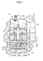
- a two-cylinder type two-stage compression rotary compressor 10 which is of an internal low pressure type according to an embodiment of the present invention includes: a cylindrical closed steel container 12; an electric motor 14 disposed in the closed container 14; and a rotary compression mechanism 18 drivable by a rotary shaft 16 of the electric motor 14.
- the cylindrical closed container 12 includes an oil tank it is base and comprises a container main body 12A for accommodating therein the electric motor 14 and the rotary compression mechanism 18, and a bowl-like cover 12B for closing the upper opening of the container main body 12A. Further, a terminal (wiring is omitted) 20 for supplying power to the electric motor portion 14 is provided on the cover 12B.
- the electric motor 14 includes stator 22 annually attached along the inner peripheral surface of the upper space of the cylindrical closed container 12, and a rotor 24 inserted and arranged inside the stator 22 with a small gap therebetween.
- the rotating shaft 16 extending through the centre in the vertical direction is fixed to the rotor 24.
- the stator 22 has a layered product 26 on which a ring-like electromagnetic steel plate is superimposed thereon and a stator coil 28 wound around the layered product 26.
- the rotor 24 is formed by a layered product 30 which is an electromagnetic steel plate similar to the stator 22.
- the rotor and stator 22 together constitute an alternating current motor.
- the alternating current motor can be substituted by a DC motor in which a permanent magnet is embedded.
- the rotary compression mechanism 18 includes: a low stage side compression portion 32; a high stage side compression portion 34; and an intermediate partition plate 36 which is sandwiched between the compression portions 32, 34 and has an aperture 36a through which a portion of the rotating shaft extends.
- Each compression portion 32, 34 comprises the intermediate partition plate 36; upper and lower cylinders 38 and 40 arranged on the upper and lower sides of the intermediate partition plate 36 respectively, upper and lower rollers 46 and 48 which are fitted to upper and lower eccentric portions 42 and 44 provided on the rotary shaft 16 with a phase difference of 180 degrees in the upper and lower cylinders 38 and 40; upper and lower vanes 50 and 52 which are in contact with the upper and lower rollers 46 and 48 to partition the insides of each of the upper and lower cylinders 38 and 40 into a low pressure chamber side 38a, 40a and a high pressure chamber side 38b, 40b; and upper and lower support members 54, 56 which closes the upper and lower cylinders 38 and 40 and serve as bearings for the rotating shaft 16.
- Inlet passages 58, 60 communicate with the inside of the upper and lower cylinders 38, 40 and outlet sound absorbing chambers 62 and 64 are formed on the upper and lower support members 54, 56.
- the openings to both of the outlet sound absorbing chambers 62, 64 are closed by an upper and lower plate 66, 68.
- the upper and lower vanes 50, 52 are arranged and accommodated in radial guide grooves 60, 72 formed in the cylinder walls of the upper and lower cylinders 38, 40 so as to be capable of reciprocal movement therein.
- the vanes 50, 52 are constantly pushed against the upper and lower rollers 46, 48 by springs 74, 76.
- the compression operation of the first stage (low stage side) is carried out in the upper cylinder 38, and the compression operation of the second stage (high stage side) for further compressing the refrigerant gas which has been compressed in the upper cylinder 38 to be boosted to have an intermediate pressure is performed in the lower cylinder 40.
- the upper support member 54, the upper cylinder 38, the intermediate partition plate 36, the lower cylinder 40 and the lower supporting member 56 are arranged in the stated order and are further integrally connected and fixed together with the upper plate 66 and the lower plate 68 using a plurality of fixing bolts 78.
- An oil hole 80 orthogonal to the axis of rotation of the shaft is formed near the lower end of the rotating shaft 16 and lateral fill holes 82, 84 are formed to this oil hole 80.
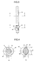
- the portion 90 of the shaft between the upper and lower eccentric portions 42, 44 is formed integrally with the shaft 16 and has a cross-sectional area is larger than the circular cross section of the remainder of the rotary shaft 16 to increase the rigidity of the rotary shaft 16.
- the cross section may be non-circular in shape.
- connecting portion 90 for connecting the upper and lower eccentric portions 42, 44 is coaxial with the rotating shaft 16
- its cross section is such that its thickness in a direction orthogonal to the direction in which the upper and lower eccentric portions 42, 44 extend from the rotary shaft 16 is greater than the thickness in the same direction in which the eccentric portions extend from the rotary shaft 16.
- a thickness dl in the direction in which the upper and lower eccentric portions 42, 44 extend from the shaft 16 is the same as the diameter d of the rotary shaft 16.
- FIG. 5 Another embodiment is shown in Figures 5 and 6.
- the non-circular cross-sectional area S2 of the connecting portion 90 is similarly larger than the non-circular cross-sectional area S1 in the foregoing embodiment (S2 > S1 > S).
- the connecting portion 90 has such a cross-sectional shape as that the thickness on the eccentricity side of the lower eccentric portion 44 is larger than the thickness on the eccentricity side of the upper eccentric portion 42.
- the cross-sectional area of the connecting portion 90 for connecting the upper and lower eccentric portions 42 and 44 integrally formed with the rotating shaft 16 is larger to increase the geometric secondary moment so that the strength (rigidity) of the rotary shaft is enhanced, thereby improving durability and reliability of the compressor.
- the increased cross-sectional area of the connecting portion 90 improves the strength (rigidity) of the shaft 16 and prevents the rotating shaft 16 from being elastically deformed.
- carbon dioxide (CO 2 ) is used as a refrigerant and any existing oil such as mineral oil, alkylbenzene oil, ether oil, ester oil is used as lubricating oil.
- Refrigerant inlet pipes 92, 94 for leading the refrigerant gas into the upper and lower cylinders 38, 40 through the inlet passages 58 and 60 and the outlet sound absorbing chambers 62 and 64 and refrigerant outlet pipes 96 and 98 for discharging the compressed refrigerant gas are respectively connected to the upper and lower support members 54, 56. Additionally, refrigerant pipes 100, 102, 104 and 106 are respectively connected to these refrigerant inlet pipes 92, 94 and the refrigerant outlet pipes 96, 98. Also, an accumulator 108 is connected between the refrigerant pipings 102, 104. It is to be noted that a mounting seat 110 is provided on the outer bottom surface of the closed container 112.
- the low-pressure refrigerant gas is sucked from an inlet port 112 into the low pressure chamber side 38a of the upper cylinder 38 through the refrigerant piping 100, the refrigerant inlet pipe 92 and the inlet passage 58 formed to the upper supporting member 54 and is compressed by the operation of the upper and roller 46 and the upper vane 50 to an intermediate pressure. It is then sent from the high pressure chamber side 38b of the upper cylinder 38 to the accumulator 108 on the outside of the closed container 12 through the outlet portion 114, the outlet sound absorbing chamber 62 formed to the upper supporting member 54, the refrigerant outlet pipe 96 and the refrigerant piping 102.
- the refrigerant gas with an intermediate pressure which has been sucked from the inlet portion 116 to the low pressure chamber side 40a of the lower cylinder 40 through the accumulator 108, the refrigerant piping 104, the refrigerant inlet pipe 94 and the inlet passage 60 formed to the lower supporting member 56 is subjected to the second-stage compression by the operation of the lower roller 48 and the lower vane 52 to become a high-pressure refrigerant gas. It is then sent from the high pressure chamber side 40b to an external refrigerant circuit (not shown) constituting a freezing cycle through the outlet port 118, the outlet sound absorbing chamber 64 formed to the lower supporting member 56, the refrigerant outlet pipe 98 and the refrigerant piping 106.
- Rotation of the rotating shaft 16 causes the lubricating oil reserved at the bottom of the closed container 12 to move up through the vertical oil hole 80 formed to the shaft centre of the rotating shaft 16, and the oil then flows out from the lateral fill holes 82 and 84 and is supplied to the bearing portion of the rotating shaft 16 and the upper and lower eccentric portions 42 and 44.
- the rotating shaft 16 and the upper and lower eccentric portions 42 and 44 can smoothly rotate.
- the rotating shaft can be prevented from being elastically deformed even if a difference between a high pressure and a low pressure is large, and the two-cylinder type two-stage compression rotary compressor having the excellent durability and the high reliability can be provided.
Landscapes
- Engineering & Computer Science (AREA)
- Mechanical Engineering (AREA)
- General Engineering & Computer Science (AREA)
- Applications Or Details Of Rotary Compressors (AREA)
Abstract
Description
Claims (9)
- A two stage rotary compressor including first and second cylinders (38, 40) separated by an intermediate partition plate (36) and first and second compressing elements (42, 44) disposed in the first and second cylinders (38, 40) respectfully, the compressing elements (42, 44) being formed on a rotary shaft (16) spaced from each other by a portion (90) of the shaft (16) that extends through an aperture (36a) in the intermediate partition plate (36), characterised in that the cross-sectional area of said portion (90) of the shaft (16) between the compressing elements (42, 44) lying in a plane at right angles to the axis of rotation of the shaft is greater than the cross-sectional area of the shaft lying in any other parallel plane.
- A compressor according to claim 1, wherein the cross section of the portion (90) of the shaft (16) between the compressing elements (42, 44) is non-circular in shape.
- A compressor according to claim 1 or 2, wherein the compressing elements (42, 44) comprise eccentrically positioned cylindrical members on the shaft (16), one member (42) being arranged 180 degrees out of phase with the other member (44).
- A compressor according to claim 3, wherein the portion (90) of the shaft (16) has a first dimension substantially equal to the diameter of the remainder of the shaft (16) in a direction in which the eccentric members (42, 44) extend from the shaft (16) and a second dimension greater than the diameter of the remainder of shaft (16) in a direction at right angles to the direction in which the eccentric members (42, 44) extend from the shaft (16).
- A compressor according to claim 3, wherein the portion (90) of the shaft (16) has a first dimension greater than the diameter of the remainder of the shaft (16) in a direction which eccentric members (42, 44) extend from the shaft (16) and a dimension substantially equal or greater than the first dimension in a direction at right angles to the direction in which the eccentric members (42, 44) extend from the shaft (16).
- A compressor according to claim 5, wherein the portion (90) of the shaft (16) is arranged eccentrically with respect to the remainder of the shaft (16).
- A two-cylindrical type two-stage rotary compressor comprising: a closed container; an electric motor portion accommodated in said closed container; two cylinders driven by a rotating shaft of said electric motor portion; and a rotary compression mechanism portion which eccentrically rotate rollers fitted to the eccentric portions provided to said rotating shaft in said respective cylinders, partitions the inside of said respective cylinders by vanes, and sucks and compresses a low-pressure refrigerant gas to be discharged, said rotary compression mechanism portion including: a low stage side compression portion for sucking a low pressure refrigerant gas to be compressed; a high stage side compression portion for sucking and compressing the refrigerant gas which is compressed by said low stage side compression portion to be boosted to have an intermediate portion; and an intermediate partition plate provided between said both compression portions to insert said rotating shaft therethrough,
wherein two eccentric portions provided to said rotating shaft has a phase difference of 180 degrees, and a connecting portion for connecting said both eccentric portions has a cross-sectional shape such that the thickness in a direction orthogonal to an eccentric direction is set larger than the thickness in the eccentric direction. - The two-cylinder type two-stage compression rotary compressor according to claim 7, wherein the cross-sectional shape of said connecting portion is non-circular.
- The two-cylinder type two-stage compression rotary compressor according to claim 7 or claim 8, wherein a cross-sectional area of said connecting portion is larger than a cross-sectional area of said rotating shaft.
Applications Claiming Priority (4)
| Application Number | Priority Date | Filing Date | Title |
|---|---|---|---|
| JP24500499 | 1999-08-31 | ||
| JP24500499 | 1999-08-31 | ||
| JP2000097487 | 2000-03-31 | ||
| JP2000097487A JP3723408B2 (en) | 1999-08-31 | 2000-03-31 | 2-cylinder two-stage compression rotary compressor |
Publications (3)
| Publication Number | Publication Date |
|---|---|
| EP1081383A2 true EP1081383A2 (en) | 2001-03-07 |
| EP1081383A3 EP1081383A3 (en) | 2001-11-07 |
| EP1081383B1 EP1081383B1 (en) | 2004-12-15 |
Family
ID=26537004
Family Applications (1)
| Application Number | Title | Priority Date | Filing Date |
|---|---|---|---|
| EP00307523A Expired - Lifetime EP1081383B1 (en) | 1999-08-31 | 2000-08-31 | Rotary compressor |
Country Status (5)
| Country | Link |
|---|---|
| US (1) | US6318981B1 (en) |
| EP (1) | EP1081383B1 (en) |
| JP (1) | JP3723408B2 (en) |
| CN (1) | CN1188601C (en) |
| DE (1) | DE60016680T2 (en) |
Cited By (4)
| Publication number | Priority date | Publication date | Assignee | Title |
|---|---|---|---|---|
| EP1405946A3 (en) * | 2002-10-01 | 2004-04-14 | Sanyo Electric Co. Ltd | Drier with refrigerant circuit |
| EP1517036A3 (en) * | 2001-09-27 | 2006-03-15 | Sanyo Electric Co., Ltd. | A high pressure pump for an internal-combustion engine |
| CN104302924A (en) * | 2012-07-31 | 2015-01-21 | 三菱重工业株式会社 | Rotary fluid machine and method for assembling same |
| EP3150758A4 (en) * | 2014-05-29 | 2017-11-29 | Qingdao Haier Drum Washing Machine Co., Ltd. | Heat pump clothes dryer with dual-exhaust compressor system and control method thereof |
Families Citing this family (18)
| Publication number | Priority date | Publication date | Assignee | Title |
|---|---|---|---|---|
| JP3389539B2 (en) * | 1999-08-31 | 2003-03-24 | 三洋電機株式会社 | Internal intermediate pressure type two-stage compression type rotary compressor |
| TW568996B (en) * | 2001-11-19 | 2004-01-01 | Sanyo Electric Co | Defroster of refrigerant circuit and rotary compressor for refrigerant circuit |
| US6929455B2 (en) | 2002-10-15 | 2005-08-16 | Tecumseh Products Company | Horizontal two stage rotary compressor |
| US6799956B1 (en) | 2003-04-15 | 2004-10-05 | Tecumseh Products Company | Rotary compressor having two-piece separator plate |
| TWI344512B (en) * | 2004-02-27 | 2011-07-01 | Sanyo Electric Co | Two-stage rotary compressor |
| US20080213116A1 (en) * | 2004-12-14 | 2008-09-04 | Young-Ju Bae | Multi-Stage Rotary Compressor |
| US7866962B2 (en) * | 2007-07-30 | 2011-01-11 | Tecumseh Products Company | Two-stage rotary compressor |
| JP5117503B2 (en) * | 2007-08-28 | 2013-01-16 | 東芝キヤリア株式会社 | Multi-cylinder rotary compressor and refrigeration cycle apparatus |
| JP5084692B2 (en) * | 2008-10-21 | 2012-11-28 | 三菱電機株式会社 | 2-cylinder rotary compressor |
| JP2010121481A (en) * | 2008-11-18 | 2010-06-03 | Mitsubishi Electric Corp | Rotary compressor |
| JP5453936B2 (en) * | 2009-06-05 | 2014-03-26 | ダイキン工業株式会社 | Multi-cylinder rotary compressor |
| US8794941B2 (en) | 2010-08-30 | 2014-08-05 | Oscomp Systems Inc. | Compressor with liquid injection cooling |
| US9267504B2 (en) | 2010-08-30 | 2016-02-23 | Hicor Technologies, Inc. | Compressor with liquid injection cooling |
| JP5441982B2 (en) * | 2011-10-31 | 2014-03-12 | 三菱電機株式会社 | Rotary compressor |
| JP5781019B2 (en) * | 2012-06-13 | 2015-09-16 | 三菱電機株式会社 | Rotary compressor |
| JP6350843B1 (en) * | 2017-10-18 | 2018-07-04 | 三菱重工サーマルシステムズ株式会社 | Rotary shaft of rotary compressor and rotary compressor |
| WO2019186695A1 (en) * | 2018-03-27 | 2019-10-03 | 東芝キヤリア株式会社 | Rotary compressor and refrigeration cycle device |
| JP7228730B1 (en) * | 2022-06-10 | 2023-02-24 | 日立ジョンソンコントロールズ空調株式会社 | Rotary compressor and air conditioner |
Family Cites Families (5)
| Publication number | Priority date | Publication date | Assignee | Title |
|---|---|---|---|---|
| US1929999A (en) * | 1933-10-10 | wilson | ||
| JPS53103212A (en) * | 1977-02-18 | 1978-09-08 | Matsushita Refrig Co | Multi cylinder rotary type compressor |
| US4204815A (en) * | 1977-12-06 | 1980-05-27 | Gast Manufacturing Corporation | Cartridge rotary vane pump |
| US4507064A (en) * | 1982-06-01 | 1985-03-26 | Vilter Manufacturing Corporation | Rotary gas compressor having rolling pistons |
| US4563137A (en) * | 1983-02-17 | 1986-01-07 | Rineer Arthur E | Rotary hydraulic energy-conversion device with two dams engaging a rotatable ring |
-
2000
- 2000-03-31 JP JP2000097487A patent/JP3723408B2/en not_active Expired - Fee Related
- 2000-08-29 US US09/650,767 patent/US6318981B1/en not_active Expired - Lifetime
- 2000-08-30 CN CNB001263110A patent/CN1188601C/en not_active Expired - Fee Related
- 2000-08-31 EP EP00307523A patent/EP1081383B1/en not_active Expired - Lifetime
- 2000-08-31 DE DE60016680T patent/DE60016680T2/en not_active Expired - Lifetime
Cited By (5)
| Publication number | Priority date | Publication date | Assignee | Title |
|---|---|---|---|---|
| EP1517036A3 (en) * | 2001-09-27 | 2006-03-15 | Sanyo Electric Co., Ltd. | A high pressure pump for an internal-combustion engine |
| EP1405946A3 (en) * | 2002-10-01 | 2004-04-14 | Sanyo Electric Co. Ltd | Drier with refrigerant circuit |
| CN104302924A (en) * | 2012-07-31 | 2015-01-21 | 三菱重工业株式会社 | Rotary fluid machine and method for assembling same |
| EP3150758A4 (en) * | 2014-05-29 | 2017-11-29 | Qingdao Haier Drum Washing Machine Co., Ltd. | Heat pump clothes dryer with dual-exhaust compressor system and control method thereof |
| US10633784B2 (en) | 2014-05-29 | 2020-04-28 | Qingdao Jiaonan Haier Washing Machine Co., Ltd. | Heat pump dryer with dual-exhaust compressor system and control method thereof |
Also Published As
| Publication number | Publication date |
|---|---|
| EP1081383B1 (en) | 2004-12-15 |
| DE60016680D1 (en) | 2005-01-20 |
| JP2001140783A (en) | 2001-05-22 |
| CN1286359A (en) | 2001-03-07 |
| JP3723408B2 (en) | 2005-12-07 |
| US6318981B1 (en) | 2001-11-20 |
| EP1081383A3 (en) | 2001-11-07 |
| CN1188601C (en) | 2005-02-09 |
| DE60016680T2 (en) | 2005-10-06 |
Similar Documents
| Publication | Publication Date | Title |
|---|---|---|
| EP1081383B1 (en) | Rotary compressor | |
| US6651458B1 (en) | Internal intermediate pressure 2-stage compression type rotary compressor | |
| US9435342B2 (en) | Horizontal type scroll compressor | |
| US8858205B2 (en) | Compressor having an inlet port formed to overlap with a roller and a cylinder-type rotor for compressing a refrigerant | |
| EP2749735B1 (en) | Compressor | |
| EP1703129B1 (en) | Rotary vane compressor | |
| US8814546B2 (en) | Compressor | |
| US9039390B2 (en) | Compressor | |
| US20050220655A1 (en) | Rolling piston and gas leakage preventing apparatus for rotary compressor having the same | |
| KR20070049969A (en) | Rotary compressor | |
| JP4007383B2 (en) | Rotary compressor | |
| US9181947B2 (en) | Compressor | |
| JP2016160911A (en) | Compressor | |
| US9394904B2 (en) | Compressor | |
| KR101337079B1 (en) | Two stage rotary compressor | |
| KR101380987B1 (en) | Rotary compressor | |
| JP4171321B2 (en) | Multistage compression compressor | |
| JP3579323B2 (en) | 2-cylinder 2-stage compression rotary compressor | |
| KR101587285B1 (en) | compressor | |
| KR101340164B1 (en) | Two stage rotary compressor | |
| JP2019035391A (en) | Compressor | |
| KR20090012860A (en) | Rotary two stage compressor | |
| KR20090012852A (en) | Rotary two stage compressor |
Legal Events
| Date | Code | Title | Description |
|---|---|---|---|
| PUAI | Public reference made under article 153(3) epc to a published international application that has entered the european phase |
Free format text: ORIGINAL CODE: 0009012 |
|
| AK | Designated contracting states |
Kind code of ref document: A2 Designated state(s): DE FR GB IT Kind code of ref document: A2 Designated state(s): AT BE CH CY DE DK ES FI FR GB GR IE IT LI LU MC NL PT SE |
|
| AX | Request for extension of the european patent |
Free format text: AL;LT;LV;MK;RO;SI |
|
| PUAL | Search report despatched |
Free format text: ORIGINAL CODE: 0009013 |
|
| AK | Designated contracting states |
Kind code of ref document: A3 Designated state(s): AT BE CH CY DE DK ES FI FR GB GR IE IT LI LU MC NL PT SE |
|
| AX | Request for extension of the european patent |
Free format text: AL;LT;LV;MK;RO;SI |
|
| 17P | Request for examination filed |
Effective date: 20020419 |
|
| AKX | Designation fees paid |
Free format text: DE FR GB IT |
|
| 17Q | First examination report despatched |
Effective date: 20030414 |
|
| GRAP | Despatch of communication of intention to grant a patent |
Free format text: ORIGINAL CODE: EPIDOSNIGR1 |
|
| GRAS | Grant fee paid |
Free format text: ORIGINAL CODE: EPIDOSNIGR3 |
|
| GRAA | (expected) grant |
Free format text: ORIGINAL CODE: 0009210 |
|
| AK | Designated contracting states |
Kind code of ref document: B1 Designated state(s): DE FR GB IT |
|
| REG | Reference to a national code |
Ref country code: GB Ref legal event code: FG4D |
|
| REF | Corresponds to: |
Ref document number: 60016680 Country of ref document: DE Date of ref document: 20050120 Kind code of ref document: P |
|
| ET | Fr: translation filed | ||
| PLBE | No opposition filed within time limit |
Free format text: ORIGINAL CODE: 0009261 |
|
| STAA | Information on the status of an ep patent application or granted ep patent |
Free format text: STATUS: NO OPPOSITION FILED WITHIN TIME LIMIT |
|
| 26N | No opposition filed |
Effective date: 20050916 |
|
| REG | Reference to a national code |
Ref country code: DE Ref legal event code: R082 Ref document number: 60016680 Country of ref document: DE Representative=s name: ROCHE, VON WESTERNHAGEN & EHRESMANN, DE Ref country code: DE Ref legal event code: R082 Ref document number: 60016680 Country of ref document: DE Representative=s name: PATENTANWAELTE OSTRIGA, SONNET, WIRTHS & VORWE, DE |
|
| REG | Reference to a national code |
Ref country code: DE Ref legal event code: R082 Ref document number: 60016680 Country of ref document: DE Representative=s name: ROCHE, VON WESTERNHAGEN & EHRESMANN, DE |
|
| PGFP | Annual fee paid to national office [announced via postgrant information from national office to epo] |
Ref country code: GB Payment date: 20140827 Year of fee payment: 15 Ref country code: FR Payment date: 20140808 Year of fee payment: 15 |
|
| PGFP | Annual fee paid to national office [announced via postgrant information from national office to epo] |
Ref country code: IT Payment date: 20140819 Year of fee payment: 15 |
|
| GBPC | Gb: european patent ceased through non-payment of renewal fee |
Effective date: 20150831 |
|
| PG25 | Lapsed in a contracting state [announced via postgrant information from national office to epo] |
Ref country code: IT Free format text: LAPSE BECAUSE OF NON-PAYMENT OF DUE FEES Effective date: 20150831 |
|
| REG | Reference to a national code |
Ref country code: FR Ref legal event code: ST Effective date: 20160429 |
|
| PG25 | Lapsed in a contracting state [announced via postgrant information from national office to epo] |
Ref country code: GB Free format text: LAPSE BECAUSE OF NON-PAYMENT OF DUE FEES Effective date: 20150831 |
|
| PG25 | Lapsed in a contracting state [announced via postgrant information from national office to epo] |
Ref country code: FR Free format text: LAPSE BECAUSE OF NON-PAYMENT OF DUE FEES Effective date: 20150831 |
|
| PGFP | Annual fee paid to national office [announced via postgrant information from national office to epo] |
Ref country code: DE Payment date: 20180821 Year of fee payment: 19 |
|
| REG | Reference to a national code |
Ref country code: DE Ref legal event code: R119 Ref document number: 60016680 Country of ref document: DE |
|
| PG25 | Lapsed in a contracting state [announced via postgrant information from national office to epo] |
Ref country code: DE Free format text: LAPSE BECAUSE OF NON-PAYMENT OF DUE FEES Effective date: 20200303 |