EP1081292A1 - Loader apparatus - Google Patents
Loader apparatus Download PDFInfo
- Publication number
- EP1081292A1 EP1081292A1 EP00402368A EP00402368A EP1081292A1 EP 1081292 A1 EP1081292 A1 EP 1081292A1 EP 00402368 A EP00402368 A EP 00402368A EP 00402368 A EP00402368 A EP 00402368A EP 1081292 A1 EP1081292 A1 EP 1081292A1
- Authority
- EP
- European Patent Office
- Prior art keywords
- section
- boom
- main boom
- loading
- bucket
- Prior art date
- Legal status (The legal status is an assumption and is not a legal conclusion. Google has not performed a legal analysis and makes no representation as to the accuracy of the status listed.)
- Withdrawn
Links
- 230000007246 mechanism Effects 0.000 claims abstract description 7
- 238000005007 materials handling Methods 0.000 description 10
- 239000004576 sand Substances 0.000 description 6
- 239000000463 material Substances 0.000 description 4
- 238000012423 maintenance Methods 0.000 description 3
- 230000010355 oscillation Effects 0.000 description 3
- 230000001174 ascending effect Effects 0.000 description 2
- 238000010586 diagram Methods 0.000 description 2
- 230000001681 protective effect Effects 0.000 description 2
- 229910000831 Steel Inorganic materials 0.000 description 1
- 238000009412 basement excavation Methods 0.000 description 1
- 230000008859 change Effects 0.000 description 1
- 238000010276 construction Methods 0.000 description 1
- 230000007423 decrease Effects 0.000 description 1
- 238000001514 detection method Methods 0.000 description 1
- 238000007599 discharging Methods 0.000 description 1
- 239000004519 grease Substances 0.000 description 1
- 238000007689 inspection Methods 0.000 description 1
- 238000000034 method Methods 0.000 description 1
- 238000012986 modification Methods 0.000 description 1
- 230000004048 modification Effects 0.000 description 1
- 230000004044 response Effects 0.000 description 1
- 239000010959 steel Substances 0.000 description 1
- 238000003466 welding Methods 0.000 description 1
Images


Classifications
-
- E—FIXED CONSTRUCTIONS
- E02—HYDRAULIC ENGINEERING; FOUNDATIONS; SOIL SHIFTING
- E02F—DREDGING; SOIL-SHIFTING
- E02F3/00—Dredgers; Soil-shifting machines
- E02F3/04—Dredgers; Soil-shifting machines mechanically-driven
- E02F3/28—Dredgers; Soil-shifting machines mechanically-driven with digging tools mounted on a dipper- or bucket-arm, i.e. there is either one arm or a pair of arms, e.g. dippers, buckets
- E02F3/34—Dredgers; Soil-shifting machines mechanically-driven with digging tools mounted on a dipper- or bucket-arm, i.e. there is either one arm or a pair of arms, e.g. dippers, buckets with bucket-arms, i.e. a pair of arms, e.g. manufacturing processes, form, geometry, material of bucket-arms directly pivoted on the frames of tractors or self-propelled machines
- E02F3/3402—Dredgers; Soil-shifting machines mechanically-driven with digging tools mounted on a dipper- or bucket-arm, i.e. there is either one arm or a pair of arms, e.g. dippers, buckets with bucket-arms, i.e. a pair of arms, e.g. manufacturing processes, form, geometry, material of bucket-arms directly pivoted on the frames of tractors or self-propelled machines the arms being telescopic
-
- E—FIXED CONSTRUCTIONS
- E02—HYDRAULIC ENGINEERING; FOUNDATIONS; SOIL SHIFTING
- E02F—DREDGING; SOIL-SHIFTING
- E02F3/00—Dredgers; Soil-shifting machines
- E02F3/04—Dredgers; Soil-shifting machines mechanically-driven
- E02F3/28—Dredgers; Soil-shifting machines mechanically-driven with digging tools mounted on a dipper- or bucket-arm, i.e. there is either one arm or a pair of arms, e.g. dippers, buckets
- E02F3/34—Dredgers; Soil-shifting machines mechanically-driven with digging tools mounted on a dipper- or bucket-arm, i.e. there is either one arm or a pair of arms, e.g. dippers, buckets with bucket-arms, i.e. a pair of arms, e.g. manufacturing processes, form, geometry, material of bucket-arms directly pivoted on the frames of tractors or self-propelled machines
- E02F3/3414—Dredgers; Soil-shifting machines mechanically-driven with digging tools mounted on a dipper- or bucket-arm, i.e. there is either one arm or a pair of arms, e.g. dippers, buckets with bucket-arms, i.e. a pair of arms, e.g. manufacturing processes, form, geometry, material of bucket-arms directly pivoted on the frames of tractors or self-propelled machines the arms being pivoted at the rear of the vehicle chassis, e.g. skid steer loader
-
- E—FIXED CONSTRUCTIONS
- E02—HYDRAULIC ENGINEERING; FOUNDATIONS; SOIL SHIFTING
- E02F—DREDGING; SOIL-SHIFTING
- E02F3/00—Dredgers; Soil-shifting machines
- E02F3/04—Dredgers; Soil-shifting machines mechanically-driven
- E02F3/28—Dredgers; Soil-shifting machines mechanically-driven with digging tools mounted on a dipper- or bucket-arm, i.e. there is either one arm or a pair of arms, e.g. dippers, buckets
- E02F3/36—Component parts
- E02F3/42—Drives for dippers, buckets, dipper-arms or bucket-arms
- E02F3/43—Control of dipper or bucket position; Control of sequence of drive operations
- E02F3/431—Control of dipper or bucket position; Control of sequence of drive operations for bucket-arms, front-end loaders, dumpers or the like
- E02F3/432—Control of dipper or bucket position; Control of sequence of drive operations for bucket-arms, front-end loaders, dumpers or the like for keeping the bucket in a predetermined position or attitude
-
- E—FIXED CONSTRUCTIONS
- E02—HYDRAULIC ENGINEERING; FOUNDATIONS; SOIL SHIFTING
- E02F—DREDGING; SOIL-SHIFTING
- E02F9/00—Component parts of dredgers or soil-shifting machines, not restricted to one of the kinds covered by groups E02F3/00 - E02F7/00
- E02F9/20—Drives; Control devices
- E02F9/2025—Particular purposes of control systems not otherwise provided for
- E02F9/2037—Coordinating the movements of the implement and of the frame
Definitions
- the present invention relates to a loader such as a skid steer loader, etc. More particularly, the present invention relates to a stable, rear end engine mounted loader apparatus having a new and improved boom mechanism and loading and unloading means.
- the skid steer loader has a second lift boom part 102 by which the lift boom base is coupled to a main frame 101 to oscillate freely.
- the base of a main lift boom 103 is coupled to the extreme end of the second lift boom 102 to oscillate freely.
- Bucket 104 which is the loading and unloading means of the loader, is mounted on the extreme end of main lift boom 103, which lengthens when bent downward, to oscillate freely. Bucket 104 oscillates freely in response to the extension of at extendable actuator 105.
- An approximately T-shaped control arm 106 is fixed at the middle of main lift boom 103.
- the extreme end of a control link 107 of prescribed length is mounted on the extreme end of control arm 106 to oscillate freely.
- the base end of control link 107 is mounted on the main frame 101 to oscillate freely.
- the extreme end of an extendable cylinder assembly 108 is attached to control arm 106.
- the base end of assembly 108 is attached to main frame 101 to respectively oscillate freely.
- the path 109 (shown dotted) of the extreme end of main lift boom 103 is an arc shaped path from the lowermost position to a specific height H, and is a vertical path from this height H to the highest lift height, as shown in the aforementioned Figure 9.
- the second lift boom part 102 is interposed between the main frame 101 and the main lift boom 103 in order to make the path 109 of the extreme end of the main lift boom 103 vertical. Consequently, the number of joints in the boom is increased. This leads to much unsteadiness of the center of oscillation in the boom after long use. Thus, the movement of the main lift boom 103 is no longer smooth. Also, it is necessary to constantly grease the joints of the boom in order to prevent this type of unsteadiness, and the time necessary for maintenance and inspection increases. Thus, the availability time for the equipment decreases.
- control arm 106 is arranged beside the driver's seat, therefore, the field of view beside the worker is blocked by the control arm 106 when the main lift boom 103 is raised or lowered. This makes it difficult for the loading and unloading to be performed properly.
- the present invention was made by focusing on the aforementioned problems, and has as an object to provide a loader which changes the path of the bucket as desired and which has minimal unsteadiness of the boom.
- a second object of the present invention is to provide a boom mechanism in a loader apparatus having a frame with a front and rear end and an engine mounted at the rear end.
- the boom mechanism includes a main boom having at least a first and second section.
- the first section is pivotally mounted on the frame substantially at the rear end thereof.
- the second section is slideably mounted on said first section so that the sections telescope with each other and the second section has a free end.
- a moving member is provided for moving the second section with respect to the first section to vary the length of the main boom.
- loading and unloading means are pivotally mounted on the free end of the second section whereby the main boom may be pivoted and telescoped to move the loading and unloading means along a path to a desired position and such means may be pivoted to a desired angle for loading and unloading.
- the moving member is a telescoping cylinder mounted on the first and second sections of the main boom.
- the cylinder is a hydraulically operated cylinder.
- the loading and unloading means may be a bucket pivotally mounted on the free end of the second section.
- the main boom has a pair of first sections respectively telescoping with a pair of second sections.
- spacing means for maintaining the pair of first sections and the pair of second sections a predetermined distance apart and wherein the moving member moves said pairs of sections simultaneously.
- the main boom may be pivoted through several inclination angles with respect to the frame.
- the boom mechanism also includes a boom angle sensor for detecting the inclination angle of the main boom and producing an output signal indicating such angle.
- a controller is included responsive to the output signal for controlling the path of the loading and unloading means.
- a plurality of sensors are provided for producing respective output signals related to the relative positions of the main boom, the frame and the loading and unloading means.
- a controller responsive to the plurality of output signals automatically controls the path of movement of the loading and unloading means.
- a desired bucket path such a movement horizontally in addition to vertically, can be obtained and the path can be changed according to the positional relationship of the obstacle and the materials handling equipment or according to the job requirements, and loading can be executed efficiently.
- the boom is composed so that the telescoping cylinder can be accommodated inside the main boom, the oil seal is not contaminated by dirt and sand falling on the telescoping cylinder, and the telescoping cylinder will remain in good condition.
- the boom dies not have a structure that obstructs the field of view beside the driver's seat, so the field of view is wide and work performance is good.
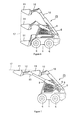
- Figure 1 shows a side view of a skid steer loader according to a preferred embodiment of the present invention.
- the traveling direction of the skid steer loader indicated by arrow F (front) - R (rear) at the bottom of this figure will be referred to as the longitudinal direction.
- the width direction of the vehicle which crosses this longitudinal direction will be referred to as the lateral direction, and left and right in the lateral direction will be determined according to the direction perceived by a worker seated in the driver's seat facing forward.
- the skid steer loader is provided with drive motor frame 1 and is provided, respectively with wheels 6 and 6 at the bottom part thereof, engine 7 at the inside rear part thereof, and boom 25 at the top part thereof.
- a pair of left and right pillars 2 are erected on the top part at the rear of drive motor frame 1, and protective screens 3 and 3 which have many holes are respectively erected at both the left and right sides in front of pillars 2.
- roof 4 is provided across the top part of the left and right protective screens 3 and 3 and a driver's cab 5, with the front having an opening for the operator to enter.
- the main boom 25 is provided with a hollow first section 8 and a hollow telescoping second section 10.
- the base of first section 8 is pivotally mounted bode engine 7 at the rear of drive motor frame 1 to oscillate freely.
- This first section 8 is moved vertically according to the extension of a main cylinder 9, which is mounted at the base to the drive motor frame 1 and at its extreme end to the middle of main boom 8, respectively.
- Telescoping boom second section 10 is inserted inside main boom first section 8 to slide freely.
- Bucket 11 which is the loading and unloading means in this embodiment, is pivotally mounted at the extreme end of telescoping boom 10 to oscillate freely and is oscillated by means of a bucket cylinder 12.
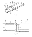
- boom 25 A perspective view of boom 25 is shown in figure 2 and a top cross section of boom 25 is shown in Figure 3. As indicated in both figures, boom 25 is provided with main boom first section 8, telescoping boom second section 10, and telescoping cylinder 16.
- main boom section 8 square columnar shaped bracket 13 and 13 made of steel are inserted into square tubing 14 and 14 and are mutually fixed by a round pipe 15 by means of, for example, welding, etc., by positions these first sections horizontally at a prescribed spacing. Also, telescoping boom section 10 is constituted by horizontally opposing square tubing 27 and 27 in which the extreme ends are bend downwardly at a prescribed spacing and mutually fixed by round pipe 26.
- Telescoping cylinder 16 is inserted into the inside part of main boom section 8 and the cylinder base thereof is fixed to the internal wall of section 8. Also, the extreme end of the piston of telescoping cylinder 16 is fixed to the wall of telescoping boom second section 10 which is inserted inside of main boom 8 to slide freely. Consequently, telescoping boom section 10 slides inside of boom section 8 by the extension of telescoping cylinder 16. Thus, the extension and retraction of cylinder 16 moves section 10 respectively out from section 8 and back into section 8, as desired.
- the distance that section 10 extends out from Section 8 may be designated as the stroke distance.
- an operating lever (not shown in the figure) for operating boom section 8 and bucket 11 is provided inside driver's cab 5. By moving this operating lever forward and backward, the inclination angle of main boom 8 can be controlled. By moving the operating lever left and right, the inclination angle of bucket 11 can be controlled.
- the skid steer loader shown in Figures 1-3 is provided with various sensors for detecting the length and angle of boom 25, and a controller which controls boom 25 based on these detected values.
- a block diagram of the sensors and controller provided on the skid steer loader is shown in Figure 4.
- a boom angle sensor 18 which detects the inclination angle of boom section 8 with respect to the frame; is mounted at the center of oscillation of section 8,.
- this boom angle sensor 18 for example, potentiometers, etc., are suitable.
- a stroke sensor 19 is integrated into telescoping cylinder 16 and detects the amount of stroke by which telescoping boom section 10 extends from section 8.
- bucket angle sensor 20 similar to boom angle sensor 18, is mounted at the center of oscillation of bucket 11 and detects the inclination angle of bucket 11 with respect to the horizontal.
- Controller 21 receives the signals from these sensors and respectively measures the inclination angle of boom section 8, the amount of stroke of telescoping boom 10, and inclination angle of bucket 11.
- operating lever sensor 33 for detecting the movement of operating lever, 32 is electrically connected to controller 21.
- mode switch 34 which specifies path 17, shown in Figures 6-8, to be followed by bucket 11, is connected to controller 21.
- Controller 21 is electrically connected to electromagnetic control valves 29, 30 and 31 arranged at the bottom part of drive motor frame 1. Controller 21 controls the discharge pressure of electromagnetic control valve 29, 30, and 31 by sending electric signals to electromagnetic control valves 29 20 and 31 based on the detection signals of sensors 18, 19, and 20, the operation of operating lever 32, and the mode signal input from mode switch 34.
- main boom control valve 29 which controls the inclination angle of main boom section 8 by driving main cylinder 9
- telescoping boom control valve 30 which controls the extension of telescoping boom section 10 by driving telescoping cylinder 16
- bucket control valve 31 which controls the inclination angle of bucket 11 by driving bucket cylinder 12.
- Electromagnetic control valves 29, 30, and 31 are respectively connected to the main valve not shown in the figure by means of hydraulic piping.
- the main valve outputs a pressure corresponding to the discharge pressures of electromagnetic control valves 29, 30, and 31, used as the control pressures and drives main cylinder 9, telescoping cylinder 16, and bucket cylinder 12.
- controller 21 can move bucket 11 so it follows the necessary path 17 according to the movement of operating lever 32. At the same time, controller 21 can execute control so that the inclination angle of bucket 11 is arranged at the desired angle.
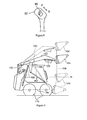
- FIGS 5-7 Examples of path 17 of bucket 11 are shown in Figures 5-7. According to Figure 5, approximately an arc path is followed by bucket 11 from the lowest position to a prescribed height (H) by ascending main boom section 8 with the length of boom 25 at its minimum without extending telescoping boom 10, as in the prior art. Then, from the height (H) to the highest lift height, boom 25 is extended by gradually extending telescoping boom section 10 so that bucket 11 follows approximately a vertical path 17.
- H prescribed height
- This type of path 17 is suited for scooping earth and sand in bucket 11 by digging into a pile of earth and sand, etc. located in front, with bucket 11, and loading this into materials handling equipment.
- the path 17 of bucket 11 can follow an arc when digging into a pile of earth and sand so the digging force is strong and more earth and sand can be scooped into bucket 11. Therefore, the digging efficiency improves. Also, if control is executed at this time so that the open part of bucket 11 becomes approximately horizontal from height (H) to the highest lift height, loss of the material loaded in the bucket is minimal.
- bucket 11 can be extended in the horizontal direction as shown in Figure 7.
- FIG. 7 For example, if there is an obstacle between the skid steer loader and the materials handling equipment and it is difficult for the skid steer loader to approach the materials handling equipment, loading into the materials handling equipment becomes possible by thus moving bucket 11 in the horizontal direction.
- the system may be set up to follow path 17 shown in Figure 5 by selecting number 1 with mode switch 34 and ascending main boom section 8: it may also be set up to follow path 17 shown in Figure 6 by selecting number 2.
- the worker can obtain the necessary path 17 by selecting a number with mode switch 34.
- toggle switch 35 is provided at the uppermost part of operating lever 32 and telescoping boom section 10 extends by telescoping cylinder 16 extending when this toggle switch 35 is pushed forward. Also telescoping boom section 10 retracts by telescoping cylinder 16 retracing when this toggle switch is pushed backward.
- boom mechanism 25 which supports bucket 11 is constituted of hollow main boom first section 8 and telescoping boom second section 10 which slides on the inside thereof.
- the telescoping boom section 10 is made to extend from main boom 8 by means of telescoping cylinder 16. Consequently, it is possible to change the length of boom 25 as desired.
- the number of joints in boom 25 is not increased in order to obtain this type of path 17 of bucket 11.
- maintenance such as greasing, etc., of the joints of boom 25 is minimized, and unsteadiness of boom 25 is minimized.
- path 17 of bucket 11 can be a desired path, for example, horizontal path, etc., in addition to a vertical path, so path 17 can be changed according to the positional relationship of obstacles and the materials handling equipment, and loading can be performed efficiently.
- Telescoping cylinder 16 is accommodated inside main boom 8 so the oil seal is not contaminated by dirt and sand falling on telescoping cylinder 16, and telescoping cylinder 16 can be always be in working condition.
- the inclination angle of bucket 11 can be controlled to be the necessary angle so it is possible to prevent loaded material from falling out by controlling the angle according to the type of quantity of material loaded in bucket 11. As one example, control can be executed so that that the open part of the bucket remains horizontal when the bucket is above a specific height. Furthermore, it is possible to determine the inclination angle of bucket 11 so that the digging force increases during excavation, etc.
- controller 21 controls path 17 of bucket 11 to be the required path based on these detected values. Consequently, path 17 of bucket 11 is automatically controlled base don a procedure programmed in controller 21 beforehand, so the burden on the worker is minimal, and moreover, an accurate path 17 can be obtained.
- telescoping boom section 10 was shown inserted inside main boom section 8 to slide freely in the aforementioned embodiment. It is not restricted to this however and can be constructed so that main boom section 8 is installed inside telescoping boom section 10.
Landscapes
- Engineering & Computer Science (AREA)
- Mining & Mineral Resources (AREA)
- Civil Engineering (AREA)
- General Engineering & Computer Science (AREA)
- Structural Engineering (AREA)
- Mechanical Engineering (AREA)
- Operation Control Of Excavators (AREA)
Abstract
Description
- The present invention relates to a loader such as a skid steer loader, etc. More particularly, the present invention relates to a stable, rear end engine mounted loader apparatus having a new and improved boom mechanism and loading and unloading means.
- Conventionally, a skid steer loader capable of raising a bucket vertically in order to perform a smooth loading job is known described in, for example, Japanese Kokai Patent application No. Hei 6[1994]-26068. Figure 9 of the present application shows a side view of the skid steer loader disclosed in such application. The prior art will be explained below based on Figure 9.
- In this figure, the skid steer loader has a second
lift boom part 102 by which the lift boom base is coupled to amain frame 101 to oscillate freely. The base of amain lift boom 103 is coupled to the extreme end of thesecond lift boom 102 to oscillate freely.Bucket 104, which is the loading and unloading means of the loader, is mounted on the extreme end ofmain lift boom 103, which lengthens when bent downward, to oscillate freely.Bucket 104 oscillates freely in response to the extension of atextendable actuator 105. - An approximately T-
shaped control arm 106 is fixed at the middle ofmain lift boom 103. The extreme end of acontrol link 107 of prescribed length is mounted on the extreme end ofcontrol arm 106 to oscillate freely. The base end ofcontrol link 107 is mounted on themain frame 101 to oscillate freely. Also, the extreme end of anextendable cylinder assembly 108 is attached tocontrol arm 106. The base end ofassembly 108 is attached tomain frame 101 to respectively oscillate freely. - When the
cylinder assembly 108 is extended or retracted thebucket 104 is raised or lowered according to this type of construction, the path 109 (shown dotted) of the extreme end ofmain lift boom 103 is an arc shaped path from the lowermost position to a specific height H, and is a vertical path from this height H to the highest lift height, as shown in the aforementioned Figure 9. - However, there are problems, described below, in the prior art disclosed in the aforementioned Japanese Kokai Patent Application No. Hei 6[1994]-26068.
- According to the illustrated prior art, the second
lift boom part 102 is interposed between themain frame 101 and themain lift boom 103 in order to make thepath 109 of the extreme end of themain lift boom 103 vertical. Consequently, the number of joints in the boom is increased. This leads to much unsteadiness of the center of oscillation in the boom after long use. Thus, the movement of themain lift boom 103 is no longer smooth. Also, it is necessary to constantly grease the joints of the boom in order to prevent this type of unsteadiness, and the time necessary for maintenance and inspection increases. Thus, the availability time for the equipment decreases. - Furthermore, the
control arm 106 is arranged beside the driver's seat, therefore, the field of view beside the worker is blocked by thecontrol arm 106 when themain lift boom 103 is raised or lowered. This makes it difficult for the loading and unloading to be performed properly. - Also, with the increase in loading work in confined spaces in recent years, a skid steer loader is required which is capable of more readily changing the path of the
bucket 104 to correspond with the position of materials handling equipment such as a dump truck, etc. However, according to the prior art, the path of the extreme end of themain lift boom 103 namely, the path ofbucket 104 is always fixed, which is a problem. - The present invention was made by focusing on the aforementioned problems, and has as an object to provide a loader which changes the path of the bucket as desired and which has minimal unsteadiness of the boom.
- A second object of the present invention is to provide a boom mechanism in a loader apparatus having a frame with a front and rear end and an engine mounted at the rear end. The boom mechanism includes a main boom having at least a first and second section. The first section is pivotally mounted on the frame substantially at the rear end thereof. The second section is slideably mounted on said first section so that the sections telescope with each other and the second section has a free end. A moving member is provided for moving the second section with respect to the first section to vary the length of the main boom. Finally, loading and unloading means are pivotally mounted on the free end of the second section whereby the main boom may be pivoted and telescoped to move the loading and unloading means along a path to a desired position and such means may be pivoted to a desired angle for loading and unloading.
- In a further embodiment, the moving member is a telescoping cylinder mounted on the first and second sections of the main boom.
- In still a further embodiment, the cylinder is a hydraulically operated cylinder.
- The loading and unloading means may be a bucket pivotally mounted on the free end of the second section.
- In another preferred embodiment, the main boom has a pair of first sections respectively telescoping with a pair of second sections. In addition, spacing means for maintaining the pair of first sections and the pair of second sections a predetermined distance apart and wherein the moving member moves said pairs of sections simultaneously.
- In yet a further preferred embodiment, the main boom may be pivoted through several inclination angles with respect to the frame. The boom mechanism also includes a boom angle sensor for detecting the inclination angle of the main boom and producing an output signal indicating such angle. Finally, a controller is included responsive to the output signal for controlling the path of the loading and unloading means.
- In an improved embodiment a plurality of sensors are provided for producing respective output signals related to the relative positions of the main boom, the frame and the loading and unloading means. A controller responsive to the plurality of output signals automatically controls the path of movement of the loading and unloading means.
- In a further improved embodiment, the plurality of sensors include a boom angle sensor which detects the angle of inclination between the main boom and the frame and produces a first output signal. A stroke sensor detects the amount of stroke by which the second section of the main boom extends from the first section and produces a second output signal. Finally, a loading and unloading means sensor detects the inclination angle between this means and the second section of the main boom and produces a third output signal. The controller is responsive to the first, second and third output signals and controls the path which the loading and unloading means must follow based on the detected values.
- Also, a desired bucket path, such a movement horizontally in addition to vertically, can be obtained and the path can be changed according to the positional relationship of the obstacle and the materials handling equipment or according to the job requirements, and loading can be executed efficiently.
- Moreover, the number of boom joints are not increased, as required in the prior art, to obtain this type of bucket path, so maintenance such as greasing, etc., of the boom joints becomes unnecessary, and unsteadiness of the boom is also minimized.
- Also, for example, if the boom is composed so that the telescoping cylinder can be accommodated inside the main boom, the oil seal is not contaminated by dirt and sand falling on the telescoping cylinder, and the telescoping cylinder will remain in good condition.
- Furthermore, the boom dies not have a structure that obstructs the field of view beside the driver's seat, so the field of view is wide and work performance is good.
- Other features and advantages of the present invention will be understood from the following detailed description of the preferred embodiments made with reference to the appended drawings, in which:
- Figure 1 is a side view of a skid steer loader according to an embodiment of the present invention;
- Figure 2 is a perspective view of the boom portion of Figure 1;
- Figure 3 is a cross section of the boom shown in Figure 2.
- Figure 4 is a block diagram of the sensors and the controller used to control movement of the boom and bucket;
- Figure 5 is a side view showing an example of the pat of the bucket;
- Figure 6 is a side view showing an example of a further path of the bucket;
- Figure 7 is a side view showing an example of still another path of the bucket possible within the preferred embodiment;
- Figure 8 is a perspective view of an operating lever for the loader; and
- Figure 9 is a side view of a prior art skid steer loader.
-
- Below, an embodiment according to the principles of the present invention will be explained in detail with reference to the figures. In the embodiment, the elements identical to those in Figure 9 are given the same numerals, and duplicate explanation is omitted.
- Figure 1 shows a side view of a skid steer loader according to a preferred embodiment of the present invention. The traveling direction of the skid steer loader indicated by arrow F (front) - R (rear) at the bottom of this figure will be referred to as the longitudinal direction. The width direction of the vehicle which crosses this longitudinal direction will be referred to as the lateral direction, and left and right in the lateral direction will be determined according to the direction perceived by a worker seated in the driver's seat facing forward.
- In Figure 1, the skid steer loader is provided with
drive motor frame 1 and is provided, respectively withwheels engine 7 at the inside rear part thereof, andboom 25 at the top part thereof. A pair of left andright pillars 2 are erected on the top part at the rear ofdrive motor frame 1, andprotective screens pillars 2. Then,roof 4 is provided across the top part of the left and rightprotective screens cab 5, with the front having an opening for the operator to enter. - The
main boom 25 is provided with a hollowfirst section 8 and a hollow telescopingsecond section 10. The base offirst section 8 is pivotally mounted bodeengine 7 at the rear ofdrive motor frame 1 to oscillate freely. Thisfirst section 8 is moved vertically according to the extension of amain cylinder 9, which is mounted at the base to thedrive motor frame 1 and at its extreme end to the middle ofmain boom 8, respectively. - Telescoping boom
second section 10 is inserted inside main boomfirst section 8 to slide freely.Bucket 11, which is the loading and unloading means in this embodiment, is pivotally mounted at the extreme end oftelescoping boom 10 to oscillate freely and is oscillated by means of abucket cylinder 12. - A perspective view of
boom 25 is shown in figure 2 and a top cross section ofboom 25 is shown in Figure 3. As indicated in both figures,boom 25 is provided with main boomfirst section 8, telescoping boomsecond section 10, andtelescoping cylinder 16. - In
main boom section 8, square columnar shapedbracket square tubing round pipe 15 by means of, for example, welding, etc., by positions these first sections horizontally at a prescribed spacing. Also,telescoping boom section 10 is constituted by horizontally opposingsquare tubing round pipe 26. - Telescoping
cylinder 16 is inserted into the inside part ofmain boom section 8 and the cylinder base thereof is fixed to the internal wall ofsection 8. Also, the extreme end of the piston oftelescoping cylinder 16 is fixed to the wall of telescoping boomsecond section 10 which is inserted inside ofmain boom 8 to slide freely. Consequently,telescoping boom section 10 slides inside ofboom section 8 by the extension of telescopingcylinder 16. Thus, the extension and retraction ofcylinder 16moves section 10 respectively out fromsection 8 and back intosection 8, as desired. The distance thatsection 10 extends out fromSection 8 may be designated as the stroke distance. - At this time, the internal circumferential surfaces of the four sides of
main boom section 8 are machined to smoothly correspond with the spacing ofsquare tubing 27 ofboom section 10. Consequently, the dimensional difference of the space between thebrackets boom section 8 and the space betweensquare tubing telescoping boom section 109 is compensated for andboom section 10 is made to slide smoothly inboom section 8. - Also, an operating lever (not shown in the figure) for
operating boom section 8 andbucket 11 is provided inside driver'scab 5. By moving this operating lever forward and backward, the inclination angle ofmain boom 8 can be controlled. By moving the operating lever left and right, the inclination angle ofbucket 11 can be controlled. - The skid steer loader shown in Figures 1-3 is provided with various sensors for detecting the length and angle of
boom 25, and a controller which controlsboom 25 based on these detected values. A block diagram of the sensors and controller provided on the skid steer loader is shown in Figure 4. - First of all, a
boom angle sensor 18 which detects the inclination angle ofboom section 8 with respect to the frame; is mounted at the center of oscillation ofsection 8,. As thisboom angle sensor 18, for example, potentiometers, etc., are suitable. - Also, a
stroke sensor 19 is integrated intotelescoping cylinder 16 and detects the amount of stroke by whichtelescoping boom section 10 extends fromsection 8. Furthermore,bucket angle sensor 20 similar toboom angle sensor 18, is mounted at the center of oscillation ofbucket 11 and detects the inclination angle ofbucket 11 with respect to the horizontal. - These sensors are connected electrically to a
controller 21 arranged insidedrive motor frame 1 or inside driver'scab 5.Controller 21 receives the signals from these sensors and respectively measures the inclination angle ofboom section 8, the amount of stroke oftelescoping boom 10, and inclination angle ofbucket 11. - Also operating
lever sensor 33 for detecting the movement of operating lever, 32 is electrically connected tocontroller 21. Furthermore,mode switch 34, which specifiespath 17, shown in Figures 6-8, to be followed bybucket 11, is connected tocontroller 21. -
Controller 21 is electrically connected toelectromagnetic control valves drive motor frame 1.Controller 21 controls the discharge pressure ofelectromagnetic control valve electromagnetic control valves 29 20 and 31 based on the detection signals ofsensors lever 32, and the mode signal input frommode switch 34. - As the electromagnetic control valves, there are such examples as main
boom control valve 29 which controls the inclination angle ofmain boom section 8 by drivingmain cylinder 9, telescopingboom control valve 30 which controls the extension oftelescoping boom section 10 by drivingtelescoping cylinder 16, andbucket control valve 31 which controls the inclination angle ofbucket 11 by drivingbucket cylinder 12. -
Electromagnetic control valves electromagnetic control valves main cylinder 9, telescopingcylinder 16, andbucket cylinder 12. - By being constituted as described above,
controller 21 can movebucket 11 so it follows thenecessary path 17 according to the movement of operatinglever 32. At the same time,controller 21 can execute control so that the inclination angle ofbucket 11 is arranged at the desired angle. - Examples of
path 17 ofbucket 11 are shown in Figures 5-7. According to Figure 5, approximately an arc path is followed bybucket 11 from the lowest position to a prescribed height (H) by ascendingmain boom section 8 with the length ofboom 25 at its minimum without extendingtelescoping boom 10, as in the prior art. Then, from the height (H) to the highest lift height,boom 25 is extended by gradually extendingtelescoping boom section 10 so thatbucket 11 follows approximately avertical path 17. - This type of
path 17 is suited for scooping earth and sand inbucket 11 by digging into a pile of earth and sand, etc. located in front, withbucket 11, and loading this into materials handling equipment. In other words, thepath 17 ofbucket 11 can follow an arc when digging into a pile of earth and sand so the digging force is strong and more earth and sand can be scooped intobucket 11. Therefore, the digging efficiency improves. Also, if control is executed at this time so that the open part ofbucket 11 becomes approximately horizontal from height (H) to the highest lift height, loss of the material loaded in the bucket is minimal. - The case where
bucket 11 follows avertical path 17 from the lowest position to the highest lift height is shown in Figure 6. By controlling so thatbucket 11 follows a vertical path, it is possible to load into the materials handling equipment without moving the skid steer loader too much away from when the load is loaded intobucket 11 at the lowest position. Therefore, the loading efficiency improves. - Also, by lower the inclination angle of
main boom section 8 while extendingtelescoping boom section 10 after lifting the load to a prescribed height,bucket 11 can be extended in the horizontal direction as shown in Figure 7. For example, if there is an obstacle between the skid steer loader and the materials handling equipment and it is difficult for the skid steer loader to approach the materials handling equipment, loading into the materials handling equipment becomes possible by thus movingbucket 11 in the horizontal direction. - It is preferable for selection of these types of
various paths 17 to be executed by the operator operatingmode switch 34 to specify the path tocontroller 21. For example, the system may be set up to followpath 17 shown in Figure 5 by selectingnumber 1 withmode switch 34 and ascending main boom section 8: it may also be set up to followpath 17 shown in Figure 6 by selectingnumber 2. Thus, the worker can obtain thenecessary path 17 by selecting a number withmode switch 34. - Also, whether the inclination angle of
bucket 11 is to be controlled bycontroller 21 or by the operator with the operation of operatinglever 32 can be selected at this time withmode switch 34. - It is also possible to obtain the desired
path 17 by means of manual operation instead of controllingpath 17 ofbucket 11 withcontroller 21 as was described above. It is preferable for even this type of manual operation mode to be selected withmode switch 34. - An example of an operating lever enabling manual operation is shown in Figure 8. In this figure,
toggle switch 35 is provided at the uppermost part of operatinglever 32 andtelescoping boom section 10 extends by telescopingcylinder 16 extending when thistoggle switch 35 is pushed forward. Also telescopingboom section 10 retracts by telescopingcylinder 16 retracing when this toggle switch is pushed backward. - By the worker operating the
aforementioned toggle switch 35 and operatinglever 32 simultaneously the desiredpath 17 ofbucket 11 can be obtained, in accordance with the surrounding situation. - As explained above, according to the illustrated embodiment,
boom mechanism 25 which supportsbucket 11 is constituted of hollow main boomfirst section 8 and telescoping boomsecond section 10 which slides on the inside thereof. Thetelescoping boom section 10 is made to extend frommain boom 8 by means of telescopingcylinder 16. Consequently, it is possible to change the length ofboom 25 as desired. Thus it is possible, for example, whenbucket 11 has been lowered, to makepath 17 at the extreme end ofbucket 11 approximately vertical by making the boom the shortest at a slightly raised position and then gradually extendingboom 25 while raising it further. - In other words, when loading material onto materials handling equipment such as a truck, etc., it is possible to bring
bucket 11 even closer to the materials handling equipment than in a case whenpath 17 ofbucket 11 is arc shaped without moving the skid steer loader, and loading can be performed efficiently. - Moreover, the number of joints in
boom 25 is not increased in order to obtain this type ofpath 17 ofbucket 11. Thus, maintenance such as greasing, etc., of the joints ofboom 25 is minimized, and unsteadiness ofboom 25 is minimized. - Also,
path 17 ofbucket 11 can be a desired path, for example, horizontal path, etc., in addition to a vertical path, sopath 17 can be changed according to the positional relationship of obstacles and the materials handling equipment, and loading can be performed efficiently. - Telescoping
cylinder 16 is accommodated insidemain boom 8 so the oil seal is not contaminated by dirt and sand falling on telescopingcylinder 16, andtelescoping cylinder 16 can be always be in working condition. - Also, the inclination angle of
bucket 11 can be controlled to be the necessary angle so it is possible to prevent loaded material from falling out by controlling the angle according to the type of quantity of material loaded inbucket 11. As one example, control can be executed so that that the open part of the bucket remains horizontal when the bucket is above a specific height. Furthermore, it is possible to determine the inclination angle ofbucket 11 so that the digging force increases during excavation, etc. - Furthermore, there is no structural member, as in the prior art, obstructing the field of view besides the driver's
cab 5 so the field of view is wide and the work performance is good. - Also, the inclination angle of
main boom section 8 and the amount of stroke of telescoping,boom section 10 are detected andcontroller 21controls path 17 ofbucket 11 to be the required path based on these detected values. Consequently,path 17 ofbucket 11 is automatically controlled base don a procedure programmed incontroller 21 beforehand, so the burden on the worker is minimal, and moreover, anaccurate path 17 can be obtained. - In the aforementioned embodiment, an explanation was given in which operation of
cylinders electromagnetic control valves cylinders main valve 27 according to the electric signal output fromcontroller 21. - Also,
telescoping boom section 10 was shown inserted insidemain boom section 8 to slide freely in the aforementioned embodiment. It is not restricted to this however and can be constructed so thatmain boom section 8 is installed insidetelescoping boom section 10. - The invention has been described above in detail with respect to preferred embodiments. However, it is clear that various modifications can be carried out within the scope of the present invention which is defined by the following claims.
Claims (12)
- In a loader having a frame with a front and rear end and an engine mounted at said rear end, a boom mechanism characterized by:a main boom having at least a first and second section, said first section being pivotally mounted on said frame substantially at said rear end thereof, said second section being slideably mounted on said first section so that said sections telescope with each other and said second section has a free end;a moving member for moving said second section with respect to said first section to vary the length of said main boom; andloading and unloading means pivotally mounted on said free end of said second section whereby said main boom may be pivoted and telescoped to move said loading and unloading means along a path to a desired position and said means may be pivoted to a desired loading and unloading.
- Apparatus as claimed in claim 1 characterized in that said moving member is a telescoping cylinder mounted on said first and second sections of said main boom.
- Apparatus as claimed in claim 2 characterized in that said telescoping cylinder is mounted within said first section of said main boom.
- Apparatus as claimed in claim 2 or 3 characterized in that said telescoping cylinder is a hydraulically operated cylinder.
- Apparatus as claimed in any one of claims 1-4 characterized in that a second moving member is provided for moving said first section through different inclination angles with respect to said frame.
- Apparatus as claimed in claim 5 characterized in that said second moving member is a hydraulically operated cylinder having one end connected to said frame and a second end connected to said first section of said main boom.
- Apparatus as claimed in any one of claims 1-6 characterized in that said loading and unloading means is a bucket pivotally mounted on said free end of said second section.
- Apparatus as claimed in any one of claims 1-7 characterized in that said second section slides inside of said first section to vary the length of said main boom.
- Apparatus as claimed in any one of claims 1-8 characterized in that said main boom has a pair of first sections respectively telescoping with a pair of second sections; and spacing means for maintaining said pair of first sections and said pair of second sections a predetermined distance apart and wherein said moving member moves said pairs of sections simultaneously.
- Apparatus as claimed in any one of claims 1-9 characterized in that said main boom may be pivoted through several inclination angles with respect to said frame and further comprising:a boom angle sensor for detecting said inclination angle of said main boom and producing an output signal indicating said angle; anda controller responsive to said output signal for controlling said path of said loading and unloading means.
- Apparatus as claimed in any one of claims 1-9 characterized by a plurality of sensorsproducing respective output signals related to the relative positions of said main boom, said frame and said loading and unloading means; anda controller responsive to said plurality of output signals for automatically controlling the path of movement of said loading and unloading means.
- Apparatus as claimed in claim 11 characterized in that said plurality of sensors include a boom angle sensor which detects the angle of inclination between said main boom and said frame and producing a first output signal;a stroke sensor for detecting the amount of stroke by which said second section of said main boom extends from said first section and producing a second output signal;
anda loading and unloading means sensor which detects the inclination angle between said means and said second section of said main boom and produces a third output signal, wherein said controller is responsive to said first, second and third output signals and controls the path which said loading and unloading means must follow based on said detected values.
Applications Claiming Priority (2)
| Application Number | Priority Date | Filing Date | Title |
|---|---|---|---|
| JP24576599 | 1999-08-31 | ||
| JP24576599A JP4041861B2 (en) | 1999-08-31 | 1999-08-31 | Loading work vehicle |
Publications (1)
| Publication Number | Publication Date |
|---|---|
| EP1081292A1 true EP1081292A1 (en) | 2001-03-07 |
Family
ID=17138482
Family Applications (1)
| Application Number | Title | Priority Date | Filing Date |
|---|---|---|---|
| EP00402368A Withdrawn EP1081292A1 (en) | 1999-08-31 | 2000-08-28 | Loader apparatus |
Country Status (2)
| Country | Link |
|---|---|
| EP (1) | EP1081292A1 (en) |
| JP (1) | JP4041861B2 (en) |
Cited By (21)
| Publication number | Priority date | Publication date | Assignee | Title |
|---|---|---|---|---|
| WO2004007337A1 (en) * | 2002-07-15 | 2004-01-22 | Stock Of Sweden Ab | A device in a vehicle adapted to handle loads |
| ITBO20090189A1 (en) * | 2009-03-26 | 2010-09-27 | Cast Group S R L | EARTH MOVING MACHINE |
| DE202009005058U1 (en) * | 2009-07-24 | 2010-12-30 | Hubtex Maschinenbau Gmbh & Co. Kg | Converter transport vehicle |
| CN102605813A (en) * | 2012-03-29 | 2012-07-25 | 厦门厦工机械股份有限公司 | Perpendicular hoisting working device of slippage loader |
| US8342789B2 (en) | 2008-06-26 | 2013-01-01 | Kubota Corporation | Loader work machine |
| US8459927B2 (en) | 2009-07-29 | 2013-06-11 | Cnh America Llc | Vertical lift arm device |
| US8827625B2 (en) | 2010-08-25 | 2014-09-09 | Cnh Industrial America Llc | Load arm arrangement for a skid-steer loader |
| CN104110047A (en) * | 2014-06-23 | 2014-10-22 | 山东科技大学 | Mining built-in scraper type bucket rear-unloading loader |
| CN104975624A (en) * | 2015-06-30 | 2015-10-14 | 江苏柳工机械有限公司 | Telescopic type working device of sliding-steering loader |
| US9267262B2 (en) | 2014-06-06 | 2016-02-23 | Caterpillar Sarl | Lift arm linkage with extension cylinder |
| US9458602B2 (en) | 2012-02-15 | 2016-10-04 | Hitachi Construction Machinery Co., Ltd. | Dual-arm work machine |
| CN107859080A (en) * | 2017-11-26 | 2018-03-30 | 江苏沪越机械设备有限公司 | A kind of Multipurpose dredger |
| WO2018112211A3 (en) * | 2016-12-16 | 2018-08-30 | Clark Equipment Company | Loader with telescopic lift arm |
| USD832552S1 (en) | 2017-10-12 | 2018-10-30 | Clark Equipment Company | Lift arm for loader |
| USD832551S1 (en) | 2017-10-12 | 2018-10-30 | Clark Equipment Company | Loader |
| EP3358087B1 (en) | 2017-02-03 | 2019-08-14 | Manitou Bf | Construction machine, in particular for construction site, and method for controlling such a machine |
| CN113323043A (en) * | 2021-07-13 | 2021-08-31 | 湖南一二机械科技有限公司 | Mining shovel car |
| EP4148190A1 (en) * | 2021-09-14 | 2023-03-15 | Robert Bosch GmbH | Method for controlling an equipment movement of a working equipment of a working machine and working machine |
| EP4148188A1 (en) * | 2021-09-14 | 2023-03-15 | Robert Bosch GmbH | Method for controlling equipment rotation of working equipment of working machine, and working machine |
| US20230304252A1 (en) * | 2020-09-08 | 2023-09-28 | The Toro Company | Compact utility loader with synchronized lift and extension of working tool attachment |
| GB2619080A (en) * | 2022-05-27 | 2023-11-29 | Bamford Excavators Ltd | A working machine |
Families Citing this family (4)
| Publication number | Priority date | Publication date | Assignee | Title |
|---|---|---|---|---|
| JP3828856B2 (en) | 2002-10-21 | 2006-10-04 | ヤンマー株式会社 | Skid steer loader |
| JP4919869B2 (en) * | 2007-04-27 | 2012-04-18 | 株式会社アイチコーポレーション | Work vehicle |
| JP5346553B2 (en) * | 2008-10-31 | 2013-11-20 | 株式会社クボタ | Front loader and extension used for front loader |
| DE102009006168A1 (en) * | 2009-01-26 | 2010-07-29 | Jungheinrich Aktiengesellschaft | Counterbalanced trucks |
Citations (8)
| Publication number | Priority date | Publication date | Assignee | Title |
|---|---|---|---|---|
| US2791341A (en) * | 1954-11-08 | 1957-05-07 | Mid Western Ind Inc | Tractor mounted power unit |
| US4082197A (en) * | 1976-10-12 | 1978-04-04 | Caterpillar Tractor Co. | Articulated high lift vehicle |
| US4306832A (en) * | 1979-04-30 | 1981-12-22 | Gregory Schmiesing | Front end loader with improved reach controls |
| FR2552415A1 (en) * | 1983-09-23 | 1985-03-29 | Noirot Yves | Loader with side access and a telescopic arm |
| US4741662A (en) * | 1980-03-14 | 1988-05-03 | Gregory Schmiesing | Material handling equipment |
| US4910662A (en) * | 1985-03-19 | 1990-03-20 | Sundstrand-Sauer | Boom control system |
| US4999022A (en) * | 1987-06-05 | 1991-03-12 | Veys Jeff M | Bucket-blade attachment for tractors |
| US5257177A (en) * | 1990-09-29 | 1993-10-26 | Danfoss A/S | Apparatus for controlling the movement of hydraulically movable work equipment and a path control arrangement |
-
1999
- 1999-08-31 JP JP24576599A patent/JP4041861B2/en not_active Expired - Fee Related
-
2000
- 2000-08-28 EP EP00402368A patent/EP1081292A1/en not_active Withdrawn
Patent Citations (8)
| Publication number | Priority date | Publication date | Assignee | Title |
|---|---|---|---|---|
| US2791341A (en) * | 1954-11-08 | 1957-05-07 | Mid Western Ind Inc | Tractor mounted power unit |
| US4082197A (en) * | 1976-10-12 | 1978-04-04 | Caterpillar Tractor Co. | Articulated high lift vehicle |
| US4306832A (en) * | 1979-04-30 | 1981-12-22 | Gregory Schmiesing | Front end loader with improved reach controls |
| US4741662A (en) * | 1980-03-14 | 1988-05-03 | Gregory Schmiesing | Material handling equipment |
| FR2552415A1 (en) * | 1983-09-23 | 1985-03-29 | Noirot Yves | Loader with side access and a telescopic arm |
| US4910662A (en) * | 1985-03-19 | 1990-03-20 | Sundstrand-Sauer | Boom control system |
| US4999022A (en) * | 1987-06-05 | 1991-03-12 | Veys Jeff M | Bucket-blade attachment for tractors |
| US5257177A (en) * | 1990-09-29 | 1993-10-26 | Danfoss A/S | Apparatus for controlling the movement of hydraulically movable work equipment and a path control arrangement |
Cited By (29)
| Publication number | Priority date | Publication date | Assignee | Title |
|---|---|---|---|---|
| WO2004007337A1 (en) * | 2002-07-15 | 2004-01-22 | Stock Of Sweden Ab | A device in a vehicle adapted to handle loads |
| US8342789B2 (en) | 2008-06-26 | 2013-01-01 | Kubota Corporation | Loader work machine |
| ITBO20090189A1 (en) * | 2009-03-26 | 2010-09-27 | Cast Group S R L | EARTH MOVING MACHINE |
| DE202009005058U1 (en) * | 2009-07-24 | 2010-12-30 | Hubtex Maschinenbau Gmbh & Co. Kg | Converter transport vehicle |
| US8459927B2 (en) | 2009-07-29 | 2013-06-11 | Cnh America Llc | Vertical lift arm device |
| US8827625B2 (en) | 2010-08-25 | 2014-09-09 | Cnh Industrial America Llc | Load arm arrangement for a skid-steer loader |
| US9458602B2 (en) | 2012-02-15 | 2016-10-04 | Hitachi Construction Machinery Co., Ltd. | Dual-arm work machine |
| CN102605813B (en) * | 2012-03-29 | 2015-05-13 | 厦门厦工机械股份有限公司 | Perpendicular hoisting working device of slippage loader |
| CN102605813A (en) * | 2012-03-29 | 2012-07-25 | 厦门厦工机械股份有限公司 | Perpendicular hoisting working device of slippage loader |
| US9267262B2 (en) | 2014-06-06 | 2016-02-23 | Caterpillar Sarl | Lift arm linkage with extension cylinder |
| CN104110047A (en) * | 2014-06-23 | 2014-10-22 | 山东科技大学 | Mining built-in scraper type bucket rear-unloading loader |
| CN104975624A (en) * | 2015-06-30 | 2015-10-14 | 江苏柳工机械有限公司 | Telescopic type working device of sliding-steering loader |
| WO2018112211A3 (en) * | 2016-12-16 | 2018-08-30 | Clark Equipment Company | Loader with telescopic lift arm |
| US10626576B2 (en) | 2016-12-16 | 2020-04-21 | Clark Equipment Company | Loader with telescopic lift arm |
| CN110088406A (en) * | 2016-12-16 | 2019-08-02 | 克拉克设备公司 | Loading machine with telescopic lift arm |
| EP3358087B1 (en) | 2017-02-03 | 2019-08-14 | Manitou Bf | Construction machine, in particular for construction site, and method for controlling such a machine |
| EP3358087B2 (en) † | 2017-02-03 | 2024-12-18 | Manitou Bf | Construction machine, in particular for construction site, and method for controlling such a machine |
| USD832552S1 (en) | 2017-10-12 | 2018-10-30 | Clark Equipment Company | Lift arm for loader |
| USD832551S1 (en) | 2017-10-12 | 2018-10-30 | Clark Equipment Company | Loader |
| CN107859080A (en) * | 2017-11-26 | 2018-03-30 | 江苏沪越机械设备有限公司 | A kind of Multipurpose dredger |
| US20230304252A1 (en) * | 2020-09-08 | 2023-09-28 | The Toro Company | Compact utility loader with synchronized lift and extension of working tool attachment |
| AU2021341818B2 (en) * | 2020-09-08 | 2026-07-23 | The Toro Company | Compact utility loader with synchronized lift and extension of working tool attachment |
| CN113323043A (en) * | 2021-07-13 | 2021-08-31 | 湖南一二机械科技有限公司 | Mining shovel car |
| EP4148190A1 (en) * | 2021-09-14 | 2023-03-15 | Robert Bosch GmbH | Method for controlling an equipment movement of a working equipment of a working machine and working machine |
| EP4148188A1 (en) * | 2021-09-14 | 2023-03-15 | Robert Bosch GmbH | Method for controlling equipment rotation of working equipment of working machine, and working machine |
| DE102021210113A1 (en) | 2021-09-14 | 2023-03-16 | Robert Bosch Gesellschaft mit beschränkter Haftung | Method of controlling an attachment rotation of a work attachment of a work machine and work machine |
| DE102021210112A1 (en) | 2021-09-14 | 2023-03-16 | Robert Bosch Gesellschaft mit beschränkter Haftung | Method for controlling an equipment movement of a work equipment of a work machine and work machine |
| GB2619080A (en) * | 2022-05-27 | 2023-11-29 | Bamford Excavators Ltd | A working machine |
| EP4283050A1 (en) * | 2022-05-27 | 2023-11-29 | J.C. Bamford Excavators Limited | A working machine |
Also Published As
| Publication number | Publication date |
|---|---|
| JP4041861B2 (en) | 2008-02-06 |
| JP2001064990A (en) | 2001-03-13 |
Similar Documents
| Publication | Publication Date | Title |
|---|---|---|
| JP4041861B2 (en) | Loading work vehicle | |
| EP2543777B1 (en) | Damper operation control device for a work vehicle, and damper operation control method | |
| CN112513381B (en) | Hydraulic drive device for excavating construction machine | |
| JP4223893B2 (en) | Control method and control device for hydraulic pump for work machine of work vehicle | |
| CN110462137B (en) | work vehicle | |
| KR102649042B1 (en) | work vehicle | |
| KR20110069942A (en) | Position control device and position control method for construction equipment | |
| US11898327B2 (en) | Hydraulic system for working machine | |
| WO2022070954A1 (en) | Construction machine | |
| WO1996029479A1 (en) | Device for controlling bulldozing blade of bulldozer and method thereof | |
| JP2006249709A (en) | Lift arm device in work vehicle and work vehicle including the same | |
| CN105324539B (en) | The control method of working truck, the control device of working truck and working truck | |
| JP4483681B2 (en) | Lift arm device for work vehicle and work vehicle | |
| CN114423907B (en) | Engineering machinery | |
| WO2004083099A1 (en) | Self-propelled working machine | |
| EP0397076A1 (en) | Electrohydraulic system | |
| JP3537099B2 (en) | Bucket angle control device for industrial vehicles | |
| CN113396256B (en) | Work machine and work machine control method | |
| JP7130606B2 (en) | work machine | |
| JP4201122B2 (en) | Reach forklift | |
| JP5320003B2 (en) | Hydraulic control device for work machine | |
| JPH06185093A (en) | Wheel loader front controller | |
| JP2000335899A (en) | Work vehicle boom operation control device | |
| EP4722457A1 (en) | Work machine | |
| JP4308617B2 (en) | Boom type work vehicle horizontal and vertical movement control device |
Legal Events
| Date | Code | Title | Description |
|---|---|---|---|
| PUAI | Public reference made under article 153(3) epc to a published international application that has entered the european phase |
Free format text: ORIGINAL CODE: 0009012 |
|
| AK | Designated contracting states |
Kind code of ref document: A1 Designated state(s): GB IT |
|
| AX | Request for extension of the european patent |
Free format text: AL;LT;LV;MK;RO;SI |
|
| 17P | Request for examination filed |
Effective date: 20010810 |
|
| AKX | Designation fees paid |
Free format text: GB IT |
|
| 17Q | First examination report despatched |
Effective date: 20070105 |
|
| REG | Reference to a national code |
Ref country code: DE Ref legal event code: 8566 |
|
| STAA | Information on the status of an ep patent application or granted ep patent |
Free format text: STATUS: THE APPLICATION IS DEEMED TO BE WITHDRAWN |
|
| 18D | Application deemed to be withdrawn |
Effective date: 20110301 |