EP1081079A2 - Sheet conveying apparatus - Google Patents
Sheet conveying apparatus Download PDFInfo
- Publication number
- EP1081079A2 EP1081079A2 EP00117715A EP00117715A EP1081079A2 EP 1081079 A2 EP1081079 A2 EP 1081079A2 EP 00117715 A EP00117715 A EP 00117715A EP 00117715 A EP00117715 A EP 00117715A EP 1081079 A2 EP1081079 A2 EP 1081079A2
- Authority
- EP
- European Patent Office
- Prior art keywords
- sheet
- rotary member
- discharging
- sheet discharging
- conveying
- Prior art date
- Legal status (The legal status is an assumption and is not a legal conclusion. Google has not performed a legal analysis and makes no representation as to the accuracy of the status listed.)
- Granted
Links
- 238000007599 discharging Methods 0.000 claims abstract description 171
- 238000003825 pressing Methods 0.000 claims abstract description 23
- 230000001105 regulatory effect Effects 0.000 claims description 50
- 238000011144 upstream manufacturing Methods 0.000 claims description 30
- 230000010355 oscillation Effects 0.000 claims description 27
- 230000002093 peripheral effect Effects 0.000 claims description 4
- 230000000717 retained effect Effects 0.000 claims description 2
- 238000004804 winding Methods 0.000 claims description 2
- 238000007639 printing Methods 0.000 description 8
- 239000010410 layer Substances 0.000 description 5
- 238000004140 cleaning Methods 0.000 description 3
- 238000007373 indentation Methods 0.000 description 3
- 239000000758 substrate Substances 0.000 description 3
- 239000002344 surface layer Substances 0.000 description 3
- VYPSYNLAJGMNEJ-UHFFFAOYSA-N Silicium dioxide Chemical compound O=[Si]=O VYPSYNLAJGMNEJ-UHFFFAOYSA-N 0.000 description 2
- 238000004040 coloring Methods 0.000 description 2
- 239000000428 dust Substances 0.000 description 2
- 239000001023 inorganic pigment Substances 0.000 description 2
- 239000007788 liquid Substances 0.000 description 2
- 238000000034 method Methods 0.000 description 2
- 238000013459 approach Methods 0.000 description 1
- 230000006399 behavior Effects 0.000 description 1
- 238000005452 bending Methods 0.000 description 1
- 238000009835 boiling Methods 0.000 description 1
- 239000003086 colorant Substances 0.000 description 1
- 239000002131 composite material Substances 0.000 description 1
- 230000010485 coping Effects 0.000 description 1
- 238000000151 deposition Methods 0.000 description 1
- 230000008021 deposition Effects 0.000 description 1
- 238000001514 detection method Methods 0.000 description 1
- 238000001035 drying Methods 0.000 description 1
- 238000005530 etching Methods 0.000 description 1
- 238000001704 evaporation Methods 0.000 description 1
- 230000008020 evaporation Effects 0.000 description 1
- 238000007667 floating Methods 0.000 description 1
- 238000004519 manufacturing process Methods 0.000 description 1
- 239000000463 material Substances 0.000 description 1
- 239000004033 plastic Substances 0.000 description 1
- 230000003405 preventing effect Effects 0.000 description 1
- 230000002940 repellent Effects 0.000 description 1
- 239000005871 repellent Substances 0.000 description 1
- 239000011347 resin Substances 0.000 description 1
- 229920005989 resin Polymers 0.000 description 1
- 230000000452 restraining effect Effects 0.000 description 1
- 238000005096 rolling process Methods 0.000 description 1
- 239000004065 semiconductor Substances 0.000 description 1
- 239000000377 silicon dioxide Substances 0.000 description 1
- 238000004544 sputter deposition Methods 0.000 description 1
- XLYOFNOQVPJJNP-UHFFFAOYSA-N water Substances O XLYOFNOQVPJJNP-UHFFFAOYSA-N 0.000 description 1
Images




Classifications
-
- B—PERFORMING OPERATIONS; TRANSPORTING
- B65—CONVEYING; PACKING; STORING; HANDLING THIN OR FILAMENTARY MATERIAL
- B65H—HANDLING THIN OR FILAMENTARY MATERIAL, e.g. SHEETS, WEBS, CABLES
- B65H29/00—Delivering or advancing articles from machines; Advancing articles to or into piles
- B65H29/12—Delivering or advancing articles from machines; Advancing articles to or into piles by means of the nip between two, or between two sets of, moving tapes or bands or rollers
- B65H29/14—Delivering or advancing articles from machines; Advancing articles to or into piles by means of the nip between two, or between two sets of, moving tapes or bands or rollers and introducing into a pile
-
- B—PERFORMING OPERATIONS; TRANSPORTING
- B65—CONVEYING; PACKING; STORING; HANDLING THIN OR FILAMENTARY MATERIAL
- B65H—HANDLING THIN OR FILAMENTARY MATERIAL, e.g. SHEETS, WEBS, CABLES
- B65H27/00—Special constructions, e.g. surface features, of feed or guide rollers for webs
-
- B—PERFORMING OPERATIONS; TRANSPORTING
- B65—CONVEYING; PACKING; STORING; HANDLING THIN OR FILAMENTARY MATERIAL
- B65H—HANDLING THIN OR FILAMENTARY MATERIAL, e.g. SHEETS, WEBS, CABLES
- B65H29/00—Delivering or advancing articles from machines; Advancing articles to or into piles
- B65H29/20—Delivering or advancing articles from machines; Advancing articles to or into piles by contact with rotating friction members, e.g. rollers, brushes, or cylinders
- B65H29/22—Delivering or advancing articles from machines; Advancing articles to or into piles by contact with rotating friction members, e.g. rollers, brushes, or cylinders and introducing into a pile
-
- B—PERFORMING OPERATIONS; TRANSPORTING
- B65—CONVEYING; PACKING; STORING; HANDLING THIN OR FILAMENTARY MATERIAL
- B65H—HANDLING THIN OR FILAMENTARY MATERIAL, e.g. SHEETS, WEBS, CABLES
- B65H2402/00—Constructional details of the handling apparatus
- B65H2402/50—Machine elements
- B65H2402/52—Bearings, e.g. magnetic or hydrostatic bearings
-
- B—PERFORMING OPERATIONS; TRANSPORTING
- B65—CONVEYING; PACKING; STORING; HANDLING THIN OR FILAMENTARY MATERIAL
- B65H—HANDLING THIN OR FILAMENTARY MATERIAL, e.g. SHEETS, WEBS, CABLES
- B65H2404/00—Parts for transporting or guiding the handled material
- B65H2404/10—Rollers
- B65H2404/13—Details of longitudinal profile
- B65H2404/133—Limited number of active elements on common axis
-
- B—PERFORMING OPERATIONS; TRANSPORTING
- B65—CONVEYING; PACKING; STORING; HANDLING THIN OR FILAMENTARY MATERIAL
- B65H—HANDLING THIN OR FILAMENTARY MATERIAL, e.g. SHEETS, WEBS, CABLES
- B65H2404/00—Parts for transporting or guiding the handled material
- B65H2404/10—Rollers
- B65H2404/13—Details of longitudinal profile
- B65H2404/134—Axle
- B65H2404/1345—Axle with two or more degrees of freedom
-
- B—PERFORMING OPERATIONS; TRANSPORTING
- B65—CONVEYING; PACKING; STORING; HANDLING THIN OR FILAMENTARY MATERIAL
- B65H—HANDLING THIN OR FILAMENTARY MATERIAL, e.g. SHEETS, WEBS, CABLES
- B65H2404/00—Parts for transporting or guiding the handled material
- B65H2404/10—Rollers
- B65H2404/18—Rollers composed of several layers
- B65H2404/181—Rollers composed of several layers with cavities or projections at least at one layer
-
- B—PERFORMING OPERATIONS; TRANSPORTING
- B65—CONVEYING; PACKING; STORING; HANDLING THIN OR FILAMENTARY MATERIAL
- B65H—HANDLING THIN OR FILAMENTARY MATERIAL, e.g. SHEETS, WEBS, CABLES
- B65H2511/00—Dimensions; Position; Numbers; Identification; Occurrences
- B65H2511/20—Location in space
- B65H2511/21—Angle
- B65H2511/216—Orientation, e.g. with respect to direction of movement
-
- B—PERFORMING OPERATIONS; TRANSPORTING
- B65—CONVEYING; PACKING; STORING; HANDLING THIN OR FILAMENTARY MATERIAL
- B65H—HANDLING THIN OR FILAMENTARY MATERIAL, e.g. SHEETS, WEBS, CABLES
- B65H2511/00—Dimensions; Position; Numbers; Identification; Occurrences
- B65H2511/20—Location in space
- B65H2511/24—Irregularities, e.g. in orientation or skewness
-
- B—PERFORMING OPERATIONS; TRANSPORTING
- B65—CONVEYING; PACKING; STORING; HANDLING THIN OR FILAMENTARY MATERIAL
- B65H—HANDLING THIN OR FILAMENTARY MATERIAL, e.g. SHEETS, WEBS, CABLES
- B65H2601/00—Problem to be solved or advantage achieved
- B65H2601/20—Avoiding or preventing undesirable effects
- B65H2601/25—Damages to handled material
- B65H2601/251—Smearing
-
- B—PERFORMING OPERATIONS; TRANSPORTING
- B65—CONVEYING; PACKING; STORING; HANDLING THIN OR FILAMENTARY MATERIAL
- B65H—HANDLING THIN OR FILAMENTARY MATERIAL, e.g. SHEETS, WEBS, CABLES
- B65H2801/00—Application field
- B65H2801/03—Image reproduction devices
- B65H2801/12—Single-function printing machines, typically table-top machines
Definitions
- the present invention relates to a sheet conveying apparatus. More particularly, the present invention relates to a sheet discharging apparatus as the sheet conveying apparatus, and an image forming apparatus having this sheet discharging apparatus in which a sheet having an image formed thereon is discharged by sheet discharging means and a rotary member rotated by a rotation of the sheet discharging means while the sheet is pressed by the rotary member.
- a recorder such as a printer, a copying machine, a facsimile, or a recorder used as an output device for a composite type electronic device including a computer, a word processor, etc. or a work station.
- a recorder is constructed such that an image is recorded to a recording material (hereinafter referred to as a sheet) such as a sheet of paper, a plastic thin plate on the basis of image information.
- Such a recorder is divided into a serial type using a serial scan system for performing a main scanning operation in a direction crossing a conveying direction (sub-scanning direction) of the sheet, and a line type in which the image is recorded by only the sub-scan in the conveying direction of the sheet.
- the image is recorded (mainly scanned) by recording means mounted on a carriage which can move along the sheet. After the image is completely recorded on one line, the sheet is fed (pitch conveyance) by a predetermined amount. Thereafter, an image on the next line is recorded (mainly scanned) with respect to the sheet again stopped. Such an operation is repeated so that the recording operation of the entire sheet is performed.
- the sheet In the recorder of the line type, the sheet is set to a predetermined recording position and the recording operation on one line is collectively performed. Thereafter, the sheet is fed (pitch conveyance) by a predetermined amount, and the recording operation on the next line is further collectively performed. Such an operation is repeated so that the recording operation of the entire sheet is performed.
- an ink jet system for performing the recording operation by discharging ink from the recording means (recording head) to the sheet by utilizing thermal energy is used, the recording means is easily made compact and a high definition image can be recorded at high speed.
- running cost is inexpensive and noises are small since the ink jet system is a non-impact system. Furthermore, it is easy to record a color image by using ink of many colors. Especially, in the case of a line type using the recording means of the line type in which many discharging ports are arranged in a sheet width direction, the recording operation can be performed at higher speed.
- the recording means (recording head) with a structure having a liquid path arrangement (discharging port arrangement) of high density can be easily manufactured by using an electrothermal converting member, an electrode, a liquid path wall, a top plate, etc., which are formed on a substrate, through semiconductor manufacturing processes of etching, evaporation, sputtering, etc. so that the recorder can be made further compact.
- the recording means is easily elongated and sheet-shaped (two-dimensionally constructed), and is fully multiplied and mounted at high density by practically using the advantages of an IC technique and a micro processing technique.
- coated paper is often used as a sheet for coping with coloring, an improvement in image quality and an increase in operating speed of such a recorder.
- an ink receiving layer is formed on basic paper having an ink absorbing property by using a porous inorganic pigment.
- the coated paper having such an ink receiving layer it is possible to obtain a clear image with high image density and high resolution, and sufficiently cope with an increase in speed of a print output.
- silica disclosed in Japanese Patent Application Laid-Open No. 56-185690 is used as the porous inorganic pigment for forming such an ink receiving layer, and has an excellent coloring property.
- the sheet fed by feeding means is held by a platen in a recording region, and an image is recorded to the sheet by the recording head. Thereafter, the sheet is discharged by a sheet discharging apparatus arranged downstream of the recording head in the conveying direction.
- this sheet discharging apparatus there is one having a structure constructed of a sheet discharging roller and a spur arranged opposite to the sheet discharging roller and rotated by a rotation of the sheet discharging roller while the spur is pressed against the sheet.
- Fig. 9 is a view showing an attaching state of the spur constituting such a sheet discharging apparatus.
- a plurality of sharp projections 1a for reducing a contact area with the sheet are formed into serration on an outer circumference of this spur 1.
- the projections 1a come in contact with the sheet in this way, and the contact area with the sheet is reduced so that indentation onto the sheet on which unfixed ink is deposited just after printing, and an ink mark are restrained.
- the spur 1 is attached to a base member 3 such that the spur 1 is rotated with an elastic shaft 2 as a center, and obtains pressing force against the sheet by the elastic shaft 2. Further, the spur 1 is regulated by thrust regulating walls 3a, 3b, 3c, 3d of the base member 3 such that a rotating direction of the spur 1 is in conformity with a discharging direction A of the sheet.
- an object of the present invention is to provide a sheet discharging apparatus and an image forming apparatus having the sheet discharging apparatus in which a sheet can be discharged without causing any spur trace on a surface of the sheet.
- a sheet discharging apparatus for discharging a sheet having an image formed thereon to a sheet discharging section
- the apparatus comprising: sheet discharging means for discharging the sheet to the sheet discharging section; a rotary member having a plurality of projections formed on an outer circumferential portion thereof, the rotary member being rotated by a rotation of the sheet discharging means while pressing the sheet by the projections; and attitude changing means that changes an orientation of the rotary member in accordance with a movement of the sheet so that, when the rotary member is rotated while pressing the sheet, a rotating direction of the rotary member is in conformity with a discharging direction of the sheet.
- the attitude changing means includes a retaining member for oscillatably retaining the rotary member, and regulating members, which are opposingly arranged on both sides of the rotary member while abutting against the rotary member, for regulating an axial movement of the rotary member, and wherein the regulating members are constructed in such a manner that the regulating members abut against the rotary member upstream of a contact point of the rotary member with the sheet in the sheet discharging direction so that an oscillation center of the rotary member is located upstream of the contact in the sheet discharging direction.
- a sheet discharging apparatus wherein a distance between the regulating members opposingly arranged is gradually increased from an upstream side to a downstream side in the sheet discharging direction so that the oscillation center of the rotary member is located upstream of the contact point in the sheet discharging direction.
- a sheet discharging apparatus wherein projecting portions abutting against the rotary member are provided on the opposed regulating members upstream of the contact point in the sheet discharging direction so that the oscillation center of the rotary member is located on the upstream side in the sheet discharging direction from the contact point.
- a sheet discharging apparatus wherein the distance between the regulating members opposingly arranged on the upstream side of the contact point in the sheet discharging direction is narrowed in comparison with the distance on the downstream side so that the oscillation center of the rotary member is located upstream of the contact point in the sheet discharging direction.
- a sheet discharging apparatus wherein the rotary member is rotated about an elastic shaft as a center, and is oscillatably retained by the retaining member through the elastic shaft.
- the attitude changing means includes an oscillation member for rotatably retaining the rotary member, a retaining member for oscillatably retaining the oscillation member, and regulating members, which are opposingly arranged on both sides of the oscillation member while abutting against the oscillation member, for regulating an axial movement of the oscillation member; and wherein the regulating members are constructed in such a manner that the regulating members abut against the oscillation member upstream of a contact point of the rotary member with the sheet in the sheet discharging direction so that an oscillation center of the oscillation member is located upstream of the contact point in the sheet discharging direction.
- a sheet discharging apparatus for discharging a sheet having an image formed thereon to a sheet discharging section, the apparatus comprising: sheet discharging means for discharging the sheet to the sheet discharging section; a rotary member having a plurality of projections formed on an outer circumferential portion thereof, the rotary member being rotated by a rotation of the sheet discharging means while pressing the sheet by the projections; and supporting means for supporting the rotary member so that, when the rotary member is rotated while pressing the sheet, an orientation of the rotary member is changed in accordance with a moving direction of the sheet.
- an image forming apparatus comprising an image forming section and a sheet discharging apparatus for discharging a sheet having an image formed in the image forming section to a sheet discharging section, the sheet discharging apparatus comprising one as set forth in any one of the above apparatus.
- a sheet having an image formed thereon is discharged to a sheet discharging section by sheet discharging means and a rotary member having a plurality of projections formed on an outer circumferential portion of the rotary member, the rotary member being rotated by a rotation of the sheet discharging means while pressing the sheet.
- an orientation of the rotary member is changed by attitude changing means in accordance with a movement of the sheet so that the rotating direction of the rotary member is made coincide with a discharging direction of the sheet.
- Fig. 1 is a perspective view showing the entire structure of a recorder as one example of an image forming apparatus in accordance with a first embodiment of the present invention.
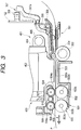
- Fig. 2 is a cross-sectional view showing the entire structure of the recorder.
- reference numeral 100 designates a recorder of an ink jet system.
- the recorder 100 is constructed of a feeding section 201, a conveying section 301, a recording section 401, a sheet discharging section 501 and a cleaning section 601.
- the feeding section 201 is constructed such that a pressure plate 202 for slantingly stacking plural sheets P and a feeding rotary member 203 for feeding the sheets P are attached to a base 204.
- a movable side guide 205 is arranged in the pressure plate 202 such that the movable side guide 205 can be moved leftward and rightward. Stacking positions of the sheets P in left and right directions are regulated by the movable side guide 205.
- An unillustrated separating means for separating the sheets P one by one and an unillustrated feed releasing means are arranged in the feeding section 201.
- the feed releasing means makes the pressure plate 202 come in contact with the feeding rotary member 203, and separates the pressure plate 202 from the feeding rotary member 203.
- the conveying section 301 has a conveying roller 302, a platen 303 and sheet end detecting means (hereinafter referred to as PE detecting means) 307.
- the conveying roller 302 constitutes conveying means for conveying a sheet P.
- the platen 303 has ribs 303a, 303b for setting the distance between the sheet P and a recording head 402 described later.
- a driving output from a sheet feeding motor 309 is deceleration-transmitted to the conveying roller 302 by a suitable gear system 309a.
- a pinch roller 304 abuts against the conveying roller 302 and is moved by frictional driving force of the conveying roller 302 and the sheet P.
- the pinch roller 304 is held by a pinch roller holder 305 biased toward the conveying roller 302 by a pinch roller spring 306.
- the pinch roller 304 comes in press contact with the conveying roller 302 and conveying force of the sheet P is generated.
- the platen 303 and the pinch roller holder 305 are extended to guide the sheet P as far as a position near an inlet of the conveying section 301 in which the sheet P is conveyed.
- the PE detecting means 307 is constructed of a PE lever 307a and a PE sensor 308. A rotating angle of the PE lever 307a is changed in accordance with existence and nonexistence of the sheet P.
- the PE sensor 308 converts a light-shielding/light-opening state into an electric signal by the change in the rotating angle of the PE lever 307a at its paper passing opposite end.
- the recording section 401 as an image forming section or image forming means is arranged downstream of the conveying roller 302 in the sheet conveying direction.
- This recording section 401 has a recording head 402 for forming an image on the basis of image information, and a carriage section 403 having a carriage 404 for detachably holding the recording head 402.
- the carriage 404 of the carriage section 403 is supported by a guide shaft 405 and a guide rail 406.
- the guide shaft 405 is arranged to reciprocate the carriage 404 in scanning in a direction (main scanning direction) perpendicular to a conveying direction of the sheet P.
- the guide rail 406 is arranged in a chassis 101 as shown in Fig. 1 to hold a rear end of the carriage 404 and maintain the distance between the recording head 402 and the sheet P.
- the guide shaft 405 is attached to the chassis 101.
- the guide rail 406 is formed by bending an upper portion of the chassis 101 in a Z-shape, and is formed integrally with the chassis 101.
- the carriage 404 is linearly driven by a carriage motor 407 attached to the chassis 101 through a timing belt 408.
- This timing belt 408 is tensioned by an idle pulley 409.
- the carriage 404 has an FFC cable 410 for transmitting a signal from an electric substrate 102 to the recording head 402.
- the recording head 402 has an unillustrated electrothermal converting member such as a heater, etc. for generating thermal energy for discharging ink.
- a film of the ink is boiled by the thermal energy applied by this electrothermal converting member.
- the ink is discharged from an unillustrated nozzle (ink discharging port) of the recording head 402 by a change in pressure caused by the growth or shrinkage of air bubbles due to the film boiling so that an image is formed on the sheet P.
- the sheet discharging section 501 is arranged downstream of the recording section 401.
- the sheet discharging section 501 discharges the sheet P to which the image is completely recorded. Further, the sheet discharging section 501 stabilizes a behavior of the sheet P during the image recording, and is constructed of a sheet discharging apparatus having two sheet discharging rollers 502, 503 as first rotary members or sheet discharging means, plural spurs 504, 505 as second rotary members or rotary members, a spur base 509 as a retaining member, a sheet discharging tray 506 (see Fig. 1) as a sheet discharging section, etc.
- the sheet discharging rollers 502, 503 are arranged in parallel with the conveying roller 302.
- the spurs 504, 505 are rotated by a movement of the sheet while these spurs press against the sheet P.
- the spur base 509 is fixed to the platen 303 and supports the spurs, etc.
- the sheet discharging tray 506 stacks the discharged sheet P.
- the sheet discharging rollers 502, 503 respectively have shaft portions 502a, 503a and plural rubber roller portions 502b, 503b press-fitted onto the shaft portions 502a, 503a or molded integrally with these shaft portions. These rubber roller portions 502b, 503b are arranged downstream of ribs 303a, 303b of the platen 303.
- These sheet discharging rollers 502, 503 are constructed such that the shaft portions 502a, 503a are attached to the platen 303 by a snap fit and driving force is transmitted from a drive output gear 310 arranged at one end of the conveying roller 302 to the sheet discharging rollers 502, 503 through a suitable gear series 310A.
- the spurs 504, 505 are arranged in positions opposed to the respective rubber roller portions 502b, 503b of the sheet discharging rollers 502, 503. These spurs 504, 505 are respectively rotated by the sheet discharging rollers 502, 503 while the spurs 504, 505 press against the sheet P.
- Peripheral speeds of the sheet discharging rollers 502, 503 are higher than that of the conveying roller 302. A conveying speed of the sheet is approximately equal to the peripheral speed of the conveying roller 302.
- the sheet discharging rollers 502, 503 give conveying force to the sheet while they are slipped with respect to the sheet P.
- the spurs 504, 505 respectively have sharp projections 504a, 505a on their outer circumferences to restrain indentations and ink marks onto the sheet P on which unfixed ink is deposited just after printing. These projections 504a, 505a are respectively formed into serration on the outer-circumferences of thin disk portions 504A, 505A shown in Fig. 5. Water repellent finishing is performed on blade edge surfaces of the projections 504a, 505a.
- SUS having about 0.1 mm in plate thickness, etc. are preferably used as the thin disk portions 504A, 505A.
- the thin disk portions 504A, 505A are respectively nipped by retaining portions 504b, 505b formed of resin (e.g., POM, etc.) having a preferable sliding property.
- Hole portions 504c, 505c are respectively formed in central portions of the retaining portions 504b, 505b.
- Spring shafts 507, 508 as supporting means for supporting the spurs 504, 505 are respectively inserted into these hole portions 504c, 505c such that orientations of the spurs 504, 505 are changed in accordance with a movement of the sheet P when the spurs 504, 505 are rotated while the spurs 504, 505 press against the sheet P.
- the spring shafts 507, 508 are elastic shafts each formed by winding a wire rod of SUS, etc. in a coil shape, and respectively have outside diameters slightly smaller than inside diameters of the hole portions 504c, 505c of the spurs 504, 505. Both ends of all the spring shafts 507, 508 are supported by the spur base 509.
- all the spurs 504, 505 can be independently moved in a vertical direction (paper thickness direction), and respectively obtain pressing force against the sheet P by the spring shafts 507, 508.
- the spurs 504, 505 are oscillatably held by the spur base 509 through the spring shafts 507, 508.
- Force for pressing the sheet against the sheet discharging rollers 502, 503 by the spurs 504, 505 is weaker than force for pressing the sheet against the conveying roller 302 by the pinch roller 304.
- a spur cleaner 510 is rotatably attached to the spur base 509. This spur cleaner 510 is rotated by rotations of the spurs 504, 505 while the spur cleaner 510 abuts against both the projections 504a, 505a of the spurs 504, 505. Thus, ink and dust deposited on the spurs 504, 505 are removed therefrom, and the deposition of contact traces of the spurs 504, 505 to the sheet P is prevented.
- the spur cleaner 510 is constructed of a open-cell porous member to remove the ink and the dust deposited on the spurs 504, 505 in this way so that the ink, etc. are easily absorbed into the spur cleaner.
- the spur cleaner 510 is attached to the spur base 509 at a suitable distance and is oscillated as the spurs 504, 505 are oscillated. However, since the spur cleaner 510 is rotated by the rotation of the spurs 504, 505, no oscillating movements of the spurs 504, 505 are regulated by the spur cleaner 510 when the spurs 504, 505 are rotated.
- Press contact amounts of the spurs 504, 505 and the spur cleaner 510 are set such that a suitable press contact force having no influence on the rotations of the spurs 504, 505 is obtained.
- the spurs 504, 505 are respectively rotated by the movement of the sheet P or the rotations of the sheet discharging rollers 502, 503, and the spur cleaner 510 is rotated by the rotations of the spurs 504, 505.
- a proximal portion of the sheet discharging tray 506 is supported by an apparatus outer mounting portion (see Fig. 2), and has a suitable height from the sheet discharging roller 503 on an upstream side so as to stack plural discharged sheets P.
- the height of the sheet discharging tray 506 is gradually increased toward a distal end portion.
- the conveying roller 302, the platen 303, the sheet discharging rollers 502, 503 and distal end portion of the sheet discharging tray 506 approximately have the same height.
- the sheet P is supported by such a structure in a substantial plane shape or a concave shape in which the sheet P is slightly pressed against the platen 303. Thus, upward floating of the sheet P in the recording section 401 is prevented.
- the cleaning section 601 is constructed of an unillustrated pump for cleaning the recording head 402, a cap 602 for restraining drying of the recording head 402 shown in Fig. 1, and drive switching means for switching driving force from the conveying roller 302 to the feeding section 201 or the pump.
- This drive switching means has a drive switching arm 603 associated with the carriage 404.
- the drive switching arm 603 can switch to a state in which the driving force is transmitted to either the feeding section 201 or the pump, or to neither of them in accordance with a moving position of the carriage 404.
- the pressure plate 202 approaches the feeding rotary member 203, and the feeding rotary member 203 is then rotated. Thus, a sheet P in an uppermost position among sheets P slantingly stacked on the pressure plate 202 is fed out. Thereafter, only the sheet P in the uppermost position is separated by a separating means and is horizontally fed to the conveying section 301.
- the sheet P fed to the conveying section 301 is guided by the platen 303 and the pinch roller holder 305, and is fed between the conveying roller 302 and the pinch roller 304.
- the PE detecting means 307 detects a leading end of the conveying sheet P by the PE lever 307a
- the sheet P is conveyed by the conveying roller 302 on the basis of this detection to a predetermined recording position.
- the feed releasing means of the feeding section 201 is operated so that the pressure plate 202 is separated from the feeding rotary member 203.
- the carriage section 403 is moved by the carriage motor 407 to a column position (a position perpendicular to the conveying direction of the sheet P) for recording the image.
- the recording head 402 is opposed to an image recording position. Thereafter, the recording head 402 discharges ink toward the sheet P by a signal from the electric substrate 102 so that the image is recorded to the sheet P.
- the above image recording per one row is repeated by desirable plural rows so that an arbitrary image is recorded on the sheet P.
- a trailing end of the sheet P is detected by the PE detecting means 307.
- the image can be recorded to a calculated trailing end position of the sheet P.
- the sheet P having the image recorded in the recording section 401 is conveyed in a state in which the sheet P is nipped by the sheet discharging rollers 502, 503 and the plural spurs 504, 505, and is discharged onto the sheet discharging tray 506.
- Regulating walls 509a to 509d, 509e to 509h as regulating members are arranged in the spur base 509 for holding these spurs 504, 505.
- the regulating walls 509a to 509d, 509e to 509h are opposingly arranged on both sides of the respective spurs 504, 505, abut against the retaining portions 504b, 505b (see Fig. 5) of the respective spurs 504, 505, and regulate movements of the spurs 504, 505 in their thrust directions and changes in attitudes of the spurs 504, 505.
- extending directions of the regulating walls 509a to 509d, 509e to 509h are respectively set to form a predetermined angle ⁇ with respect to a discharging direction A of the sheet P.
- the distances of regulating walls 509c to 509d, 509g to 509h on a downstream side in the sheet discharging direction are gradually widened in comparison with the distances of regulating walls 509a to 509b, 509e to 509f on an upstream side in the sheet discharging direction.
- the spurs 504, 505 when no rotating directions of the spurs 504, 505 are in conformity with the discharging direction A of the sheet P in discharging of the sheet, the spurs 504, 505 abut against the regulating walls 509a, 509b, 509e, 509f on the upstream side in the sheet discharging direction so that movements of these spurs in their thrust directions are regulated. Further, the spurs 504, 505 are oscillated in a direction indicated by an arrow B around points upstream of pressing points against the sheet P in the sheet discharging direction by the assistance of force from contact portions (contact points) with the sheet P located downstream of abutting portions of the spurs on these regulating walls.
- the spurs 504, 505 when no rotating directions of the spurs 504, 505 are in conformity with the discharging direction A of the sheet P, the spurs 504, 505 abut against the regulating walls 509a, 509b, 509e, 509f upstream of the contact portions with the sheet P in the sheet discharging direction.
- the spurs 504, 505 can be oscillated by the conveying force of the sheet P in a state in which the points upstream of the contact portions with the sheet P in the sheet discharging direction are set to oscillation centers.
- the spurs 504, 505 can be changed to attitudes in which the rotating directions (rolling directions) of these spurs are in conformity with the discharging direction A of the sheet P. Accordingly, the rotating directions of the spurs 504, 505 are conformed to the discharging direction A of the sheet P in accordance with the movement of the sheet P by an attitude changing means constructed of the spur base 509 and the regulating walls 509a to 509d, 509e to 509h.
- the sheet can be conveyed and discharged without separating any ink receiving layer on the printing surface and damaging the spurs even when coated paper having a weak surface layer is particularly printed. As a result, an image of good quality can be obtained.
- the spurs 504, 505 are oscillated by gradually increasing the distance between the regulating walls 509a to 509d, 509e to 509h from the upstream side to the downstream side in the discharging direction A of the sheet.
- a dedicated oscillation member may be separately arranged, and the spurs 504, 505 may be also rotatably attached to this oscillation member.
- Fig. 7 is a typical view in which a spur portion of the sheet discharging section of a recorder in accordance with this embodiment is seen from above the recorder.
- the same reference numerals as in Fig. 6 designate the same or corresponding portions.
- regulating walls 509a' to 509d', 509e' to 509h' are formed in a spur base 509. Each of these regulating walls 509a' to 509d', 509e' to 509h' is formed approximately parallel with the discharging direction A of the sheet P.
- projecting portions 509a1, 509b1, 509e1, 509f1 are respectively projected toward the spurs 504, 505 from regulating walls 509a', 509b', 509e', 509f' upstream of centers of the spurs 504, 505 in the sheet discharging direction A.
- These projecting portions 509a1, 509b1, 509e1, 509f1 abut against retaining portions 504b, 505b of the respective spurs 504, 505 so that movements of the respective spurs 504, 505 in their thrust directions and changes in attitudes caused by these movements are regulated.
- the respective spurs 504, 505 are oscillated such that their rotating directions are in conformity with the discharging direction A of the sheet P. Therefore, the sheet P can be conveyed and discharged without forming any spur trace.
- the projecting portions 509a1, 509b1, 509e1, 509f1 abut against portions near rotation centers of the respective spurs 504, 505. Therefore, sliding resistance against the rotation of each of the spurs 504, 505 is reduced, and the spurs 504, 505 smoothly follow the movement of the sheet P. As a result, spur trace preventing effects of the sheet P can be further expected.
- Fig. 8 is a schematic view in which a spur portion of the sheet discharging section of a recorder in accordance with a third embodiment of the present invention is seen from above the recorder.
- each of regulating walls 509a" to 509d", 509e" to 509h” is formed on a plane approximately parallel to the discharging direction A of the sheet P.
- the distances between regulating walls 509c" and 509d", 509g" and 509h" on a downstream side from centers of the spurs 504, 505 in the sheet discharging direction A are widened in comparison with the distances between regulating walls 509a" and 509b", 509e” and 509f" on an upstream side from these centers.
- the respective spurs 504, 505 are oscillated such that their rotating directions are in conformity with the discharging direction A of the sheet P. Therefore, the sheet P can be conveyed and discharged without forming any spur trace.
- a plurality of projections 504a, 505a are respectively formed on outer circumferential portions of the rotary members 504, 505.
- the rotary members 504, 505 are rotated by rotation of the sheet discharging device 502, 503 while the sheet P is pressed by the projections 504a, 505a.
- orientations of the rotary members 504, 505 are changed by an attitude changing device in accordance with a movement of the sheet P so that rotating directions of the rotary members 504, 505 are made coincide with a discharging direction of the sheet P.
Landscapes
- Engineering & Computer Science (AREA)
- Mechanical Engineering (AREA)
- Delivering By Means Of Belts And Rollers (AREA)
- Ink Jet (AREA)
Abstract
Description
Claims (20)
- A sheet discharging apparatus for discharging a sheet having an image formed thereon to a sheet discharging section, said apparatus comprising:sheet discharging means for discharging said sheet to said sheet discharging section;a rotary member having a plurality of projections formed on an outer circumferential portion thereof, said rotary member being rotated by a movement of said sheet discharging means while pressing said sheet by said projections; andattitude changing means that changes an orientation of said rotary member in accordance with a movement of the sheet so that, when said rotary member is rotated while pressing the sheet, a rotating direction of said rotary member is in conformity with a discharging direction of the sheet.
- A sheet discharging apparatus according to claim 1, wherein said attitude changing means includes a retaining member for oscillatably retaining said rotary member, and regulating members, which are opposingly arranged on both sides of said rotary member while abutting against said rotary member, for regulating an axial movement of said rotary member, and
wherein said regulating members are constructed in such a manner that said regulating members abut against said rotary member upstream of a contact point of said rotary member with the sheet in the sheet discharging direction so that an oscillation center of said rotary member is located upstream of said contact point in the sheet discharging direction. - A sheet discharging apparatus according to claim 2, wherein a distance between said regulating members opposingly arranged is gradually increased from an upstream side to a downstream side in the sheet discharging direction so that the oscillation center of said rotary member is located upstream of said contact point in the sheet discharging direction.
- A sheet discharging apparatus according to claim 2, wherein projecting portions abutting against said rotary member is provided on said regulating members opposingly arranged upstream of said contact point in the sheet discharging direction so that the oscillation center of said rotary member is located upstream of said contact point in the sheet discharging direction.
- A sheet discharging apparatus according to claim 2, wherein a distance between said regulating members opposingly arranged upstream of said contact point in the sheet discharging direction is narrowed than a distance between said regulating members downstream of said contact point so that the oscillation center of said rotary member is located upstream of said contact point in the sheet discharging direction.
- A sheet discharging apparatus according to claim 2, wherein said rotary member is rotated about an elastic shaft as a center, and is oscillatably retained to said retaining member with said elastic shaft.
- A sheet discharging apparatus according to claim 1, wherein said attitude changing means includes an oscillation member for rotatably retaining said rotary member, a retaining member for oscillatably retaining said oscillation member, and regulating members, which are opposingly arranged on both sides of said oscillation member while abutting against said oscillation member, for regulating an axial movement of the oscillation member; and
wherein said regulating members are constructed in such a manner that said regulating members abut against said oscillation member upstream of a contact point of said rotary member with the sheet in said sheet discharging direction so that an oscillation center of said oscillation member is located upstream of said contact point in the sheet discharging direction. - A sheet discharging apparatus for discharging a sheet having an image formed thereon to a sheet discharging section, said apparatus comprising:sheet discharging means for discharging said sheet to said sheet discharging section;a rotary member having a plurality of projections formed on an outer circumferential portion thereof, said rotary member being rotated by a movement of said sheet discharging means while pressing said sheet by said projections; andsupporting means for supporting said rotary member so that, when said rotary member is rotated while pressing the sheet, an orientation of said rotary member is changed in accordance with a moving direction of the sheet.
- An image forming apparatus comprising:an image forming section; anda sheet discharging apparatus for discharging a sheet having an image formed in said image forming section to a sheet discharging section, said sheet discharging apparatus being one as recited in any one of claims 1 to 8.
- A sheet conveying apparatus comprising:a first rotary member for conveying a sheet;a second rotary member having a plurality of projections formed on an outer circumferential portion thereof, said second rotary member being rotated by a movement of the sheet while pressing the sheet against said first rotary member by said projections; andsupporting means for supporting said second rotary member so that, when said second rotary member is rotated while pressing the sheet, an orientation of said second rotary member is changed in accordance with a moving direction of the sheet.
- A sheet conveying apparatus according to claim 10, wherein tips of said projections are brought into contact with the sheet, and are sharp.
- A sheet conveying apparatus according to claim 10, wherein said supporting means includes a shaft loosely fitted into a hole formed in said second rotary member, and said shaft has an outside diameter smaller than an inside diameter of said hole.
- A sheet conveying apparatus according to claim 12, wherein said shaft is formed by winding a wire rod in a coil shape.
- A sheet conveying apparatus according to claim 10, further comprising conveying means for conveying the sheet, said conveying means being arranged upstream of said first rotary member in the sheet moving direction.
- A sheet conveying apparatus according to claim 14, wherein said conveying means includes a conveying roller for conveying the sheet and a pinch roller for pressing the sheet against said conveying roller.
- A sheet conveying apparatus according to claim 15, wherein a peripheral speed of said first rotary member is higher than a peripheral speed of said conveying roller.
- A sheet conveying apparatus according to claim 16, wherein said first rotary member conveys the sheet while being slipped with respect to the sheet.
- A sheet conveying apparatus according to claim 17, wherein a force for pressing the sheet against the conveying roller by said pinch roller is larger than a force for pressing the sheet against said first rotary member by said second rotary member.
- A sheet conveying apparatus according to any one of claims 14 to 18, further comprising image forming means, arranged between said first rotary member and said conveying roller, for forming an image on the sheet.
- A sheet conveying apparatus according to claim 19, wherein said image forming means forms the image by discharging ink to the sheet.
Applications Claiming Priority (2)
| Application Number | Priority Date | Filing Date | Title |
|---|---|---|---|
| JP23469699 | 1999-08-20 | ||
| JP23469699A JP3762155B2 (en) | 1999-08-20 | 1999-08-20 | Paper discharge device and image forming apparatus having the same |
Publications (3)
| Publication Number | Publication Date |
|---|---|
| EP1081079A2 true EP1081079A2 (en) | 2001-03-07 |
| EP1081079A3 EP1081079A3 (en) | 2002-06-19 |
| EP1081079B1 EP1081079B1 (en) | 2005-11-02 |
Family
ID=16974988
Family Applications (1)
| Application Number | Title | Priority Date | Filing Date |
|---|---|---|---|
| EP00117715A Expired - Lifetime EP1081079B1 (en) | 1999-08-20 | 2000-08-17 | Sheet conveying and discharging apparatus |
Country Status (5)
| Country | Link |
|---|---|
| US (1) | US6457888B1 (en) |
| EP (1) | EP1081079B1 (en) |
| JP (1) | JP3762155B2 (en) |
| DE (1) | DE60023616T2 (en) |
| MX (1) | MXPA00008081A (en) |
Families Citing this family (15)
| Publication number | Priority date | Publication date | Assignee | Title |
|---|---|---|---|---|
| JP4194205B2 (en) * | 1999-05-14 | 2008-12-10 | キヤノン株式会社 | Inkjet recording device |
| JP3762228B2 (en) * | 2001-01-31 | 2006-04-05 | キヤノン株式会社 | Recording apparatus and recording method |
| US6979080B2 (en) * | 2001-08-29 | 2005-12-27 | Brother Kogyo Kabushiki Kaisha | Printer having improved recording medium feeding mechanism |
| US6848850B2 (en) * | 2001-10-24 | 2005-02-01 | Matsushita Electric Industrial Co., Ltd. | Recording apparatus |
| JP2003292224A (en) * | 2002-01-31 | 2003-10-15 | Seiko Epson Corp | Ink jet recording device and paper ejection device |
| KR100472479B1 (en) * | 2002-10-31 | 2005-03-08 | 삼성전자주식회사 | Paper guide of ink jet printer and inkjet printer having thereof |
| SG122813A1 (en) | 2003-01-24 | 2006-06-29 | Seiko Epson Corp | Printing apparatus and printing method |
| JP4208673B2 (en) * | 2003-08-29 | 2009-01-14 | キヤノン株式会社 | Recording device |
| JP4236259B2 (en) * | 2004-03-08 | 2009-03-11 | キヤノン株式会社 | Recording device |
| JP4764073B2 (en) * | 2005-06-07 | 2011-08-31 | キヤノン株式会社 | Sheet feeding apparatus and recording apparatus |
| JP5361347B2 (en) * | 2008-11-21 | 2013-12-04 | キヤノン株式会社 | RECORDING MEDIUM CONVEYING DEVICE AND RECORDING DEVICE |
| JP5703588B2 (en) * | 2010-04-19 | 2015-04-22 | セイコーエプソン株式会社 | Liquid ejector |
| JP2012206497A (en) | 2011-03-15 | 2012-10-25 | Seiko Epson Corp | Multifunction printing device |
| JP5847856B2 (en) * | 2014-01-14 | 2016-01-27 | キヤノン株式会社 | Conveying apparatus and printing apparatus provided with conveying apparatus |
| JP2017164907A (en) * | 2016-03-14 | 2017-09-21 | セイコーエプソン株式会社 | Printer |
Family Cites Families (9)
| Publication number | Priority date | Publication date | Assignee | Title |
|---|---|---|---|---|
| DE2734041C2 (en) * | 1977-07-28 | 1979-05-31 | Olympia Werke Ag, 2940 Wilhelmshaven | Paper guide for an ink jet printer |
| JPS56148585A (en) | 1980-04-21 | 1981-11-18 | Canon Inc | Recording material |
| JPS62211260A (en) | 1986-03-13 | 1987-09-17 | Mitsubishi Heavy Ind Ltd | Steering device for strip |
| US5291224A (en) * | 1989-10-27 | 1994-03-01 | Canon Kabushiki Kaisha | Sheet feeding apparatus using pairs of spur rollers |
| US5368403A (en) * | 1993-04-30 | 1994-11-29 | Hewlett-Packard Company | Carriage support system for computer driven printer |
| US5738454A (en) * | 1993-10-29 | 1998-04-14 | Hewlett-Packard Company | Multiple-function printer with common output path mechanism with floating guide ribs to accommodate media and documents of different thickness |
| US5807003A (en) * | 1995-05-24 | 1998-09-15 | Seiko Epson Corporation | Sheet discharge section for a printer |
| JP3525577B2 (en) | 1995-09-27 | 2004-05-10 | ブラザー工業株式会社 | Feed roller and inkjet printer |
| KR0184571B1 (en) * | 1996-10-16 | 1999-05-15 | 삼성전자주식회사 | Paper jam prevention structure of ink jet printer |
-
1999
- 1999-08-20 JP JP23469699A patent/JP3762155B2/en not_active Expired - Fee Related
-
2000
- 2000-08-11 US US09/636,637 patent/US6457888B1/en not_active Expired - Lifetime
- 2000-08-17 DE DE60023616T patent/DE60023616T2/en not_active Expired - Lifetime
- 2000-08-17 EP EP00117715A patent/EP1081079B1/en not_active Expired - Lifetime
- 2000-08-18 MX MXPA00008081A patent/MXPA00008081A/en unknown
Also Published As
| Publication number | Publication date |
|---|---|
| MXPA00008081A (en) | 2002-08-06 |
| EP1081079B1 (en) | 2005-11-02 |
| JP3762155B2 (en) | 2006-04-05 |
| US6457888B1 (en) | 2002-10-01 |
| JP2001058749A (en) | 2001-03-06 |
| EP1081079A3 (en) | 2002-06-19 |
| DE60023616D1 (en) | 2005-12-08 |
| DE60023616T2 (en) | 2006-07-20 |
Similar Documents
| Publication | Publication Date | Title |
|---|---|---|
| EP1081079B1 (en) | Sheet conveying and discharging apparatus | |
| EP0581276B1 (en) | Sheet conveying apparatus | |
| JP4501373B2 (en) | Recording device | |
| EP1818180B1 (en) | Sheet feeding apparatus and recording apparatus | |
| US6789889B2 (en) | Inkjet printing media handling system with advancing guide shim | |
| US20060163803A1 (en) | Feeding Device And Image Recording Apparatus Equipped With The Feeding Device | |
| JP2004276374A (en) | Recorder | |
| US7441772B2 (en) | Sheet-conveying device | |
| EP1782959B1 (en) | Ink-jet printing machine and printing method | |
| US6575459B1 (en) | Recording-medium transport device | |
| US7896566B2 (en) | Printing apparatus and printing method | |
| JPH10250181A (en) | Image recording device | |
| JP2008049555A (en) | Recording apparatus and conveyance control method | |
| JP2005096146A (en) | Recording apparatus | |
| US8896644B2 (en) | Recording apparatus | |
| JP4795168B2 (en) | Recording device | |
| JP2006044060A (en) | Recording device | |
| JP2007083500A (en) | Recording device | |
| JP2002248822A (en) | Sheet conveying device and recording device | |
| JPH07125358A (en) | Inkjet recording device | |
| JP2003145867A (en) | Recording material transport device and ink jet recording device using the same | |
| JP2002068516A (en) | Sheet conveying device and image recording device | |
| JP2009233930A (en) | Recording apparatus | |
| JP2004338155A (en) | Recording head and recording device | |
| JP2006205647A (en) | Recording device |
Legal Events
| Date | Code | Title | Description |
|---|---|---|---|
| PUAI | Public reference made under article 153(3) epc to a published international application that has entered the european phase |
Free format text: ORIGINAL CODE: 0009012 |
|
| AK | Designated contracting states |
Kind code of ref document: A2 Designated state(s): AT BE CH CY DE DK ES FI FR GB GR IE IT LI LU MC NL PT SE |
|
| AX | Request for extension of the european patent |
Free format text: AL;LT;LV;MK;RO;SI |
|
| PUAL | Search report despatched |
Free format text: ORIGINAL CODE: 0009013 |
|
| AK | Designated contracting states |
Kind code of ref document: A3 Designated state(s): AT BE CH CY DE DK ES FI FR GB GR IE IT LI LU MC NL PT SE |
|
| AX | Request for extension of the european patent |
Free format text: AL;LT;LV;MK;RO;SI |
|
| 17P | Request for examination filed |
Effective date: 20021104 |
|
| AKX | Designation fees paid |
Designated state(s): DE ES FR GB IT NL |
|
| 17Q | First examination report despatched |
Effective date: 20030410 |
|
| GRAP | Despatch of communication of intention to grant a patent |
Free format text: ORIGINAL CODE: EPIDOSNIGR1 |
|
| RTI1 | Title (correction) |
Free format text: SHEET CONVEYING AND DISCHARGING APPARATUS |
|
| GRAJ | Information related to disapproval of communication of intention to grant by the applicant or resumption of examination proceedings by the epo deleted |
Free format text: ORIGINAL CODE: EPIDOSDIGR1 |
|
| GRAP | Despatch of communication of intention to grant a patent |
Free format text: ORIGINAL CODE: EPIDOSNIGR1 |
|
| GRAS | Grant fee paid |
Free format text: ORIGINAL CODE: EPIDOSNIGR3 |
|
| GRAA | (expected) grant |
Free format text: ORIGINAL CODE: 0009210 |
|
| AK | Designated contracting states |
Kind code of ref document: B1 Designated state(s): DE ES FR GB IT NL |
|
| PG25 | Lapsed in a contracting state [announced via postgrant information from national office to epo] |
Ref country code: NL Free format text: LAPSE BECAUSE OF FAILURE TO SUBMIT A TRANSLATION OF THE DESCRIPTION OR TO PAY THE FEE WITHIN THE PRESCRIBED TIME-LIMIT Effective date: 20051102 |
|
| REG | Reference to a national code |
Ref country code: GB Ref legal event code: FG4D |
|
| REF | Corresponds to: |
Ref document number: 60023616 Country of ref document: DE Date of ref document: 20051208 Kind code of ref document: P |
|
| PG25 | Lapsed in a contracting state [announced via postgrant information from national office to epo] |
Ref country code: ES Free format text: LAPSE BECAUSE OF FAILURE TO SUBMIT A TRANSLATION OF THE DESCRIPTION OR TO PAY THE FEE WITHIN THE PRESCRIBED TIME-LIMIT Effective date: 20060213 |
|
| NLV1 | Nl: lapsed or annulled due to failure to fulfill the requirements of art. 29p and 29m of the patents act | ||
| ET | Fr: translation filed | ||
| PLBE | No opposition filed within time limit |
Free format text: ORIGINAL CODE: 0009261 |
|
| STAA | Information on the status of an ep patent application or granted ep patent |
Free format text: STATUS: NO OPPOSITION FILED WITHIN TIME LIMIT |
|
| 26N | No opposition filed |
Effective date: 20060803 |
|
| REG | Reference to a national code |
Ref country code: FR Ref legal event code: PLFP Year of fee payment: 16 |
|
| PGFP | Annual fee paid to national office [announced via postgrant information from national office to epo] |
Ref country code: DE Payment date: 20150831 Year of fee payment: 16 Ref country code: GB Payment date: 20150826 Year of fee payment: 16 |
|
| PGFP | Annual fee paid to national office [announced via postgrant information from national office to epo] |
Ref country code: FR Payment date: 20150826 Year of fee payment: 16 |
|
| PGFP | Annual fee paid to national office [announced via postgrant information from national office to epo] |
Ref country code: IT Payment date: 20150819 Year of fee payment: 16 |
|
| REG | Reference to a national code |
Ref country code: DE Ref legal event code: R119 Ref document number: 60023616 Country of ref document: DE |
|
| GBPC | Gb: european patent ceased through non-payment of renewal fee |
Effective date: 20160817 |
|
| REG | Reference to a national code |
Ref country code: FR Ref legal event code: ST Effective date: 20170428 |
|
| PG25 | Lapsed in a contracting state [announced via postgrant information from national office to epo] |
Ref country code: FR Free format text: LAPSE BECAUSE OF NON-PAYMENT OF DUE FEES Effective date: 20160831 Ref country code: GB Free format text: LAPSE BECAUSE OF NON-PAYMENT OF DUE FEES Effective date: 20160817 Ref country code: DE Free format text: LAPSE BECAUSE OF NON-PAYMENT OF DUE FEES Effective date: 20170301 |
|
| PG25 | Lapsed in a contracting state [announced via postgrant information from national office to epo] |
Ref country code: IT Free format text: LAPSE BECAUSE OF NON-PAYMENT OF DUE FEES Effective date: 20160817 |