EP1080857A2 - Bois lamellé collé et procédé de sciage de bois - Google Patents
Bois lamellé collé et procédé de sciage de bois Download PDFInfo
- Publication number
- EP1080857A2 EP1080857A2 EP00660148A EP00660148A EP1080857A2 EP 1080857 A2 EP1080857 A2 EP 1080857A2 EP 00660148 A EP00660148 A EP 00660148A EP 00660148 A EP00660148 A EP 00660148A EP 1080857 A2 EP1080857 A2 EP 1080857A2
- Authority
- EP
- European Patent Office
- Prior art keywords
- timber
- block
- glued
- sawn
- pieces
- Prior art date
- Legal status (The legal status is an assumption and is not a legal conclusion. Google has not performed a legal analysis and makes no representation as to the accuracy of the status listed.)
- Withdrawn
Links
Images


Classifications
-
- B—PERFORMING OPERATIONS; TRANSPORTING
- B27—WORKING OR PRESERVING WOOD OR SIMILAR MATERIAL; NAILING OR STAPLING MACHINES IN GENERAL
- B27M—WORKING OF WOOD NOT PROVIDED FOR IN SUBCLASSES B27B - B27L; MANUFACTURE OF SPECIFIC WOODEN ARTICLES
- B27M3/00—Manufacture or reconditioning of specific semi-finished or finished articles
- B27M3/0013—Manufacture or reconditioning of specific semi-finished or finished articles of composite or compound articles
- B27M3/0026—Manufacture or reconditioning of specific semi-finished or finished articles of composite or compound articles characterised by oblong elements connected laterally
- B27M3/0053—Manufacture or reconditioning of specific semi-finished or finished articles of composite or compound articles characterised by oblong elements connected laterally using glue
-
- B—PERFORMING OPERATIONS; TRANSPORTING
- B27—WORKING OR PRESERVING WOOD OR SIMILAR MATERIAL; NAILING OR STAPLING MACHINES IN GENERAL
- B27B—SAWS FOR WOOD OR SIMILAR MATERIAL; COMPONENTS OR ACCESSORIES THEREFOR
- B27B1/00—Methods for subdividing trunks or logs essentially involving sawing
- B27B1/007—Methods for subdividing trunks or logs essentially involving sawing taking into account geometric properties of the trunks or logs to be sawn, e.g. curvature
-
- E—FIXED CONSTRUCTIONS
- E04—BUILDING
- E04C—STRUCTURAL ELEMENTS; BUILDING MATERIALS
- E04C3/00—Structural elongated elements designed for load-supporting
- E04C3/02—Joists; Girders, trusses, or trusslike structures, e.g. prefabricated; Lintels; Transoms; Braces
- E04C3/12—Joists; Girders, trusses, or trusslike structures, e.g. prefabricated; Lintels; Transoms; Braces of wood, e.g. with reinforcements, with tensioning members
- E04C3/14—Joists; Girders, trusses, or trusslike structures, e.g. prefabricated; Lintels; Transoms; Braces of wood, e.g. with reinforcements, with tensioning members with substantially solid, i.e. unapertured, web
Definitions
- the object of the invention is a glued-laminated timber element comprising two or more longitudinal and wedge-shaped timber pieces glued together, in at least two of which pieces the grain runs in different directions, so that these timber pieces narrow in the opposite directions, so that they together form a timber element of uniform width and thickness.
- Known timber elements such as glulam timber beams, usually comprise sawn timber of uniform thickness and uniform width glued together.
- wood's grain structure is broken in timber sawn to uniform thickness and width. The breaking of the grain naturally reduces the strength of the sawn pieces and hence the strength of the timber elements formed by gluing them together. The breaking of the grain also reduces the capacity of a glued-laminated timber element, such as a glulam beam, to remain straight.
- the grain pattern also varies depending on the position of the outer and inner face of the wood. When the outer face of sawn timber is on the surface of the panel, the tree's grain may rise, forming a dangerously sharp crack.
- the warping of glulam panels made of regular sawn timber is also great because of the variations in the radial and tangential contraction of the timber pieces used in their manufacture. This causes variable contraction on the various surfaces of the glulam panel, as the inner and outer sides and edges of the timber are not present to equal degrees in the various surfaces of the glulam panel.
- the diameter of the top end of the wood used as raw material is usually at least 15 cm, which means that knots are also relatively large. Sawlog grade timber would not have knots, but it would be uneconomical to use it for manufacturing glulam panels.
- glulam elements made of wedge-shaped timber pieces have not proved to have sufficiently good properties in demanding conditions of use.
- the purpose of this invention is to eliminate the disadvantages of known elements and to create a novel kind of glulam element.
- the surfaces of wedge-shaped timber pieces have been sawn parallel to the grain, since in resawing, the block is sawn in two parallel to the heart and the opposite sides of the blanks are then resawn parallel to the grain at that point. In this way the grain structure of the wood remains intact, which has the effect that the wedge-shaped timber pieces and the elements made of them are stronger than known glulam elements.
- the glulam elements relating to the invention also have fewer seams than known glulam elements and they and also keep their straightness better than known glulam beams.
- the outside face of a wedge-shaped timber piece is made to face towards the inside of the element, and the heartwood is on the surface of the glulam element.
- the softer outside face which is more susceptible to splitting is protected inside the element, and the stronger and more weather-proof heartwood is on the surface.
- the purpose of the invention is also to create a new glulam element, such as a glulam panel, which does not have the above-mentioned disadvantages.
- the glued-laminated timber element consists of one or more such layers made up of at least two timber pieces, in which the cores of the joined timber pieces face towards the inside of the layer, mainly equidistant from both planar surfaces of the layer.
- the glulam panel relating to the invention has no harmful split sawn knots in sight, as the knots start from inside the panel towards the surface. This means that the knots stay in place well when the panel is worked, and the panel is homogeneous in terms of both appearance and knottiness. It is also light-coloured, and the heart pith is always concealed inside the product.
- the grain structure remains better intact and the panel surface obtains a scantling structure in which the grain is perpendicular to the surface. The grain pattern is even and the grain structure does not disintegrate.
- the contraction of both sides of the glulam panel is equal and the panel's lateral contraction is smaller than with present panels.
- the timber pieces used for the glulam panel can be sawn from thin pulpwood grade timber with a diameter of 7-15 cm at the top of the stem. This saves raw material and improves the wood utilisation ratio. Using sawn timber obtained from pulpwood grade for the panels is also less expensive.
- the timber pieces in the layer of the glued-laminated timber element have been joined in such a way that the core of every other timber piece faces one side of the layer and the core of every other timber piece faces the opposite side of the layer.
- the glued-laminated timber element is a glued-laminated timber beam comprising two or more layers, in each of which the cores of the timber pieces face the inside of the layer mainly equidistant from both planar surfaces of the layer.
- the glued-laminated timber element is a glued-laminated timber panel, in which one layer comprises several timber pieces, the cores of which face towards the inside of the layer mainly equidistant from both planar surfaces of the glued-laminated timber panel.
- the glued-laminated timber element is a door panel, on both sides of which mainly identical recesses or the like have been milled in such a way that also at the recesses, the cores of the timber pieces are in the centre of the door panel, mainly equidistant from the bottom of the recess.
- the timber pieces are sawn in such a way that first of all a block is sawn in which the opposite sawn sides are parallel. Then the flat block is resawn in two through the centre at the heart and at the sides it is sawn parallel to the wood's surface and grain. In this way the block produces two wedge-shaped pieces.
- a timber panel is assembled in such a way that the wedge-shaped pieces are laid together so that the heart pith remains in the middle of the panel and the knots start from the inside of the panel towards the surface. This ensures that no split sawn knots remain visible on the panel surface.
- the glulam panel has a scantling structure, in which the grain runs at right angles to the panel's surface.
- the grain structure does not break on the panel surface, because the wedge-shaped timber pieces have been sawn parallel to the wood surface and parallel to the grain. Because the grain runs perpendicular to the surface, the grain does not disintegrate from the panel surface and the grain pattern on the surface is even. Moreover, since the grain structure is always perpendicular to the surface and in the same direction, equally strong tensions are created on both panel surfaces and their contraction is equal.
- the lateral warping is less in the glulam panel than in a traditional panel. Because of the scantling structure, the warping and twisting of the glulam panel relating to the invention is less than with panels in which the angles of the grain vary in the timber pieces.
- Another advantage of the glulam panel relating to the invention is the fact that it is sawn from the top portion of trees, which means that its knottiness is sound and homogeneous, and the panel is of uniform light colour. Sawing the timber into wedge-shaped pieces at the resawing stage saves timber raw material and makes panel production less expensive.
- Another object of the invention is a novel method for sawing timber, in which method two wedge-shaped timber pieces are sawn from a tree stem in such a way
- the timber is sawn so that first normal block sawing is done, which gives the block two parallel flat surfaces. Then the block is resawn in two through the centre, and the side pieces are resawn or worked to form flat surfaces in line with the side surfaces of the stem.
- wedge-shaped timber pieces are obtained, which are blanks with sawn, hewn or planed surfaces. Then two or more blanks are joined on top of each other, side by side or end to end, with the narrowing and widening ends of the wedges either pointing in the same direction or in opposite directions. This allows glulam beams of desired size and form to be formed.
- the sawn timber pieces are relatively larger in relation to the thickness of the stem than when sawing timber of uniform thickness and width. Therefore fewer timber pieces are required and the number of glued seams needed decreases in the glulam elements relating to the invention.
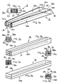
- Figures 1a and 1b show diagrammatically a block 31, which has been sawn from a round, conical stem, in such a way that parallel sawn surfaces 32a and 32b have been formed, the distance between which surfaces is, for instance, 150 mm.
- the width of the block is 150 mm throughout its whole length. Since the block 31 has been sawn symmetrically from the stem, the core 50 of the block 31 is mainly equidistant from both surfaces 32a, 32b of the block 31. Then the block 31 is resawn in two through the centre at the core 50 at the point 33, which results in two wedge-shaped block halves 34a and 34b. Next, the sides opposite the core 50 of both block halves 34a and 34b are sawn parallel to the surface along lines 35a and 35b.
- the thickness of the block halves 34a and 34b, or the wedge-shaped timber pieces 38a and 38b sawn from them, at the narrow top 36 of the block 31 is, for instance, 50 mm, and due to the conical form of the block the thickness of the halves 34a and 34b increases towards the butt 37, for instance, by 5 mm per one metre, then the thickness of the 5-metre long halves 34a and 34b of the block 31 at the butt end 37 is 75 mm.
- Figures 2a-2c show a timber element (30) seen from three different angles, which element has been formed of the wedge-shaped sawn from the halves 34a and 34b of the block 31.
- One wedge-shaped timber piece 38a has been turned around 180° so that its faces the butt end 37 of the opposite wedge-shaped timber piece 38b.
- the outer faces of both wedge-shaped timber pieces 38a and 38b have been laid to face each other and the inner faces 39 to face outwards. This way a 5-metre long, 125-mm wide and 150-mm thick timber element 30 is created, which element is in this example a glued-laminated timber beam.
- the wedge-shaped block 31 halves 34a and 34b can be joined to one another either side by side, as in figures 2a-2c, or on top of each other, as shown in figures 3a-3c.
- the stem's heart side 39 has been laid to face outwards in the glulam beam 30 and the outer face, more susceptible to splitting, to face inwards. In this way any splits occurring remain concealed inside the beam.
- Figures 4a-4c show a glulam beam with several wedge-shaped timber pieces 38 on top of each other.
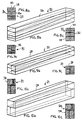
- the timber pieces 38 may also be placed end to end, as shown in figure 5, or side by side, as shown in figures 6a-6c.
- Figures 7a-7c show a glulam beam 30 in which the wedge-shaped timber pieces 38 are placed in the same direction.
- Figures 8a-8c show two beams, shown in figures 7a-7c, joined in such a way that two wedge-shaped timber pieces 38 are placed in one direction and two timber pieces in the opposite direction.
- All the glued-laminated timber elements 30 shown in figures 2-8 have only one layer of wedge-shaped timber pieces 38, which have been joined to each other in such a way that the core 50 of each timber piece 38 always faces towards the inside of the beam, i.e. is mainly equidistant from the outer surfaces 32a and 32b of the glued-laminated timber beam 30.
- the cores 50 of the timber pieces 38 can either face one another, away from one another or in the same direction in the glued-laminated timber beam 30.
- the outermost timber pieces 38 in the glued-laminated timber beam 30 have the heart face 39 of the core 50 facing outside. In this way the surface parts of all timber pieces 38 remain enclosed in the glued-laminated timber beam 30, and possible splits occurring as the timber dries will not show.
- Another essential advantage of positioning the timber pieces 38 as presented above is that in this way, there will be no elongated knots on the surface of the glued-laminated timber beam 30, which knots might cause dangerous cracks and break and come loose when the beam is being worked.
- the knots face the surface of the glued-laminated beam 30 almost at right angles, which means that they are smaller.
- the scantling structure thus formed also has the effect that the grain pattern of the glued-laminated timber beam 30, made up of timber pieces 38 glued together, is more intact and has a more pleasant appearance. Perhaps the most attractive surface pattern is achieved by placing the simultaneously sawn pairs of timber pieces 38a and 38b side by side in the glued-laminated timber beam 30.
- Figures 9a-9c and 10a-10c show two examples of glulam beams 30, which comprise several wedge-shaped timber pieces 38 placed in different directions. Both beams 30 have two pairs of timber pieces 38 placed in such a way that in both pairs two timber pieces 38 together form a rectangular prism, which can be joined to a similar rectangular prism formed by the timber pieces in the other pair.
- the heart sides of the stem face outwards and the outer faces inwards towards the inside of the beam, or vice versa.
- Figures 11a and 11b show a conical tree stem 40, from which a wedge-shaped block 31 has been sawn in such a way that it is wider at the butt end 37 of the stem 40 than at the top end 36.
- schaalboards 41 have also been sawn at both sides, parallel to the grain of the stem 40.
- Figures 12a and 12b show the sawing of a wedge-shaped block 31, outlined by flat surfaces 32a and 32b, at the resawing stage into timber pieces 38 of uniform thickness. This results in similar wedge-shaped timber pieces as above, where the sawing was done so that the block sawing was uniform-thickness and the resawing wedge-like.
- Figures 13a-13c show a glulam beam 31, in which two timber pieces 38, sawn to be wedge-shaped at the block sawing stage, have been joined one on top of the other.
- Figures 14a-15c show glulam beams 31, in which wedge-shaped timber pieces 38 have been placed both one on top of the other and side by side.
- Figures 16a and 16b show a sawing method in which only side pieces 42 are sawn from the block 31 parallel to the grain and sides of the stem. After this the block 31 can be utilised as raw material for a glulam beam.
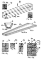
- Figures 17a-17c show vanous glulam beams 31, in which the heart face 39 of the timber pieces has been placed so as to face towards the inside of the beam 31, unlike in the previous examples.
- Figure 17d shows glued-laminated timber beam 30 where two layers 51a and 51b have been joined, in which layers the cores 50 of interconnected timber pieces 38 face the inside of each layer, mainly equidistant from both outer surfaces 32a and 32b of the layers.
- the outermost timber pieces 38 of both layers 51a and 51b in the glued-laminated timber beam 30 have been placed so that the cores 50 of the timber pieces 38 are not visible.
- the outermost timber pieces 38 in the glued-laminated timber beam 30 can also be placed so that their cores 50 face outwards, as in the single-layer solutions shown in figures 4, 6 and 8.
- a similar double-layer solution is also shown in figures 9 and 10.
- Figure 18 shows a timber element 30 relating to the invention, which in this case is a timber panel. It has been glued together from wedge-shaped timber pieces 38 in such a way that every two adjacent timber pieces 38 are placed to face in opposite directions and their heart sides are facing each other. In this way the stems' heart piths remain concealed inside the glulam panel 30.
- the panel has a scantling structure, in which the grain structure is mainly perpendicular to the surface. In this particular case this means that in the timber piece 38, the annual rings are almost at right angles to the surface of the glulam panel 30.
- Figure 18 shows the angle a between the tangent of the annual rings and the normal of the surface of the glulam panel 30, which angle is most advantageously as small as possible. The angle a should at least be less than 45°.
- the wedge-shaped timber pieces 38 have been sawn in the direction of the grain of the stem, as shown in figure 20. In this way the timber's grain structure is intact on the surface of the glulam panel
- Figure 19 shows diagrammatically how the knots 43 in the timber pieces 38 of the glulam panel 30 start from the inside of the panel 30 towards the surface. In this way the knots 43 cause the least possible harm to the surface of the glulam panel 30. Due to the symmetrical structure of the glulam panel 30 it also follows that the radial contraction of the panel is equal on both its surfaces. The scantling structure also makes it possible to achieve reduced lateral warping and contraction of the panel compared to a structure where the grain of the timber is at some other angle.
- the structure of the panel can be changed by gluing timber pieces 38 together with their heart sides facing each other or the outer sides facing each other.
- the sides can also be in a random order depending on the end use, as in the embodiment of the timber panel 30 shown in figure 21.
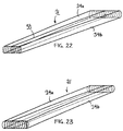
- Figure 22 shows the resawing of a block 31 sawn from a conical stem, in which process the block 31 is sawn in two along the sawing line 33, which is as close as possible to the heart pith of the tree.
- Figure 23 shows the next stage of the manufacture of the glulam panel relating to the invention, at which stage one half 34b of the block 31 has been turned around 180° and placed back to face the other half 34a of the block 31.
- stage one half 34b of the block 31 has been turned around 180° and placed back to face the other half 34a of the block 31.
- the heartwoods of both halves 34a and 34b of the block 31 are still facing each other, but the top end of one block half 34a faces the butt end of the other block half 34a.
- Figure 24 shows a conical tree stem 40 used as starting material for the glulam element. It is sawn according to prior art, first to form the block 31 shown in figure 25 using two usually vertical saw blades, which are not shown in the figure. The saw blades saw the tree stem 40 so that two opposite, parallel flat surfaces 32 are formed on the block 31. The distance of the saw blades from each other determines the width b of the block 31. In figure 25 the block 31 has been turned 90° onto its face.
- Figure 26 shows block 31, which has been sawn in two in the centre at right angles to the surface 32 along the sawing line 33, which most advantageously follows as closely as possible the heart pith at the centre of the sawn stem.
- one half 34b of the block 31 has been turned around 180° so that its top end faces the butt end 37a of the opposite half 34a of the block 31.
- the half 34b of the block 31 has also had to be turned upside down so that in the half 34b the bottom surface 32b of the block 31 now faces upwards.
- the opposite half 34a of the block 31 is still in its original position, with the surface 32a facing upwards.
- the edges 42a and 42b of the block 31 are sawn off along the sawing lines 35a and 35b, after which the shape of the pair of elements, formed by the main part of the timber element 30, i.e. the two wedge-shaped timber pieces 38a and 38b, is complete. It is shown in figure 28.
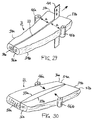
- Figure 29 shows the resawing relating to the invention, in which the block 31 is sawn in two by a saw 44.
- Figure 29 shows that the stem from which the block 31 has been sawn has been crooked. This means that the block 31 is equally crooked. Since according to the invention the block 31 is sawn as closely as possible following the core centre line of the stem, the guide rollers 45a and 45b keep the saw blade 44 in the centre of the block 31 throughout the sawing process, in which case the distance (a) of the saw blade 44 from both guide rollers 45a and 45b is equal. This means that the crookedness of the block 31 also causes the sawing line 33, following the core of the stem, to be crooked. The purpose of this arrangement is to utilise the greatest possible portion of the sawn timber. It is clear that if the resawing line of a crooked stem were straight, the sawn halves would turn out indefinitely shaped and wood would be wasted.
- Figure 30 shows the process of joining the halves 34a and 34b of the block 31 in figure 29, after the first half 34a of the block 31 has been turned around 180° so that its top end 36a becomes against the butt end 37 of the second half 34b.
- the figure shows that the crooked sawing lines 33a and 33b of the two halves 34a and 34b do not match each other as such. Therefore pressure rollers 46a and 46b have been arranged in the sawing equipment, which rollers press the halves 34a and 34b of the block 31 against each other with sufficiently strong pressure. In this way a compact, elongated beam is obtained, from which the edges can be sawn off.
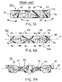
- Figure 31 shows the sawing of the edges of the pair of timber pieces 38a and 38b.
- Pressure rollers 46a and 46b press the halves 34a and 34b of the block 31 against each other, and photocells 47a and 47b or other similar members measure the form of the outer sides of the pair of timber pieces 38a and 38b.
- the edge saw blades 49a and 49b are placed at the appropriate point and the edge parts 42a and 42b are sawn off.
- Figure 32 shows a cross section of a timber panel 30a according to the prior art.
- the figure illustrates that the timber pieces 38 making up the panel 30a have been sawn at random and that they have also been placed in the timber panel 30a in no particular order.
- the cores 50 of the timber pieces 38 and correspondingly their surface parts can be located at almost any point in the panel 30a.
- the surface of the timber panel 30a may contain harmful elongated knots 43, which may cause dangerous cracks.
- splits 52 are caused and these show on the surface of the timber panel 30a. Uneven shrinkage also exerts torsional forces in different directions in the timber panel 30a, which forces cause the timber panel 30a to twist and warp.
- Figure 33 shows a cross section, analogous to figure 32, of a timber panel 30, which however has a structure that is in accordance with the invention.
- the figure shows that the cores 50 of all the timber pieces 38 of the timber panel 30 are located symmetrically near the centre line 53 of the panel 30, mainly equidistant from both surfaces 32a and 32b of the timber panel 30.
- No surface parts of the timber pieces 38 show on any surface of the timber panel 30, so that any splits 52 resulting from shrinkage remain enclosed within the timber panel 30.
- at least roughly similar shrinkage forces are present on both surfaces 32a and 32b of the timber panel 30, which means that the timber panel will not warp or twist.
- the knots 43 in the timber pieces 38 can not be harmful elongated knots, as the knots 43 face the surfaces 32a and 32b at right angles and not parallel with the surfaces.
- the timber panel 30 in the figure 33 can, for instance, be used as a floor panel, in which case its sides are provided with tongues and grooves.
- Figure 34 shows one preferred embodiment of the timber panel 30 relating to the invention.
- Figure 34 shows a massive door panel 30 similar to the one in figure 33, with recesses 54 milled into it.
- the symmetrical structure of the timber panel 30 and the position of the cores 50 of the timber pieces 38 near the centre line 53 of the panel 30 have the effect that any knots 43 occurring will not impede the cutting of the recesses 54. This is because the knots 43 are at right angles to the surfaces of the panel 30 and the parts of knots showing are therefore small and round. Any splits 52 in the timber pieces 38 also remain enclosed within the door panel 30 despite the milling of recesses.
- the outermost timber pieces 38 in the door panel 30 can be positioned advantageously, with the core 50 facing outward, as they will not show in a disturbing manner. And even if the pith ray of the core 50 of the timber piece 38 would otherwise remain visible on the door panel 30, it will be removed when the sides of the door are milled too their final shape.
- the surfaces to be joined can be sawn, honed or planed.
- the timber pieces can be wedge-shaped or straight.
- the element is made of pairs of timber pieces, in which one piece has been turned around 180° in respect to the opposite timber piece.
- Panels according to the invention can be used in furniture, floorboards, floor panels, door frames, doors or other timber products. The panels are easy to work, since they are symmetrical in structure.
- the surface side of the timber pieces faces outwards and the heart face inwards or vice versa, depending on the end use of the element.
Landscapes
- Engineering & Computer Science (AREA)
- Life Sciences & Earth Sciences (AREA)
- Wood Science & Technology (AREA)
- Architecture (AREA)
- Forests & Forestry (AREA)
- Civil Engineering (AREA)
- Structural Engineering (AREA)
- Manufacturing & Machinery (AREA)
- Mechanical Engineering (AREA)
Priority Applications (1)
| Application Number | Priority Date | Filing Date | Title |
|---|---|---|---|
| EP00660148A EP1080857A2 (fr) | 1999-09-02 | 2000-09-01 | Bois lamellé collé et procédé de sciage de bois |
Applications Claiming Priority (5)
| Application Number | Priority Date | Filing Date | Title |
|---|---|---|---|
| FI990368U | 1999-09-02 | ||
| FI990368U FI4517U1 (fi) | 1999-09-02 | 1999-09-02 | Kartiorakenteinen puupalkki ja puulevy |
| EP00660025A EP1125701A1 (fr) | 2000-02-15 | 2000-02-15 | Bois lamellé collé et méthode de fabrication |
| EP00660025 | 2000-02-15 | ||
| EP00660148A EP1080857A2 (fr) | 1999-09-02 | 2000-09-01 | Bois lamellé collé et procédé de sciage de bois |
Publications (1)
| Publication Number | Publication Date |
|---|---|
| EP1080857A2 true EP1080857A2 (fr) | 2001-03-07 |
Family
ID=27223674
Family Applications (1)
| Application Number | Title | Priority Date | Filing Date |
|---|---|---|---|
| EP00660148A Withdrawn EP1080857A2 (fr) | 1999-09-02 | 2000-09-01 | Bois lamellé collé et procédé de sciage de bois |
Country Status (1)
| Country | Link |
|---|---|
| EP (1) | EP1080857A2 (fr) |
Cited By (14)
| Publication number | Priority date | Publication date | Assignee | Title |
|---|---|---|---|---|
| WO2006005209A1 (fr) * | 2004-07-14 | 2006-01-19 | Peter Herzog-Schymura | Plaques, planches, elements et garnitures en bois massif colles et/ou lamelles-colles, dotes de joints cintres, ondules, arques, incurves ou courbes |
| EP1721714A1 (fr) * | 2005-05-02 | 2006-11-15 | Holzindustrie Leitinger Gesellschaft M.B.H. | Poutre composite en bois |
| RU2492997C1 (ru) * | 2012-06-18 | 2013-09-20 | Федеральное государственное бюджетное образовательное учреждение высшего профессионального образования "Московский государственный строительный университет" (ФГБОУ ВПО "МГСУ") | Способ изготовления опорно-ограждающих элементов стенового бруса из тонкомерного древесного сырья |
| RU2492998C1 (ru) * | 2012-06-20 | 2013-09-20 | Федеральное государственное бюджетное образовательное учреждение высшего профессионального образования "Московский государственный строительный университет" (ФГБОУ ВПО "МГСУ") | Способ изготовления опорно-ограждающих элементов стенового бруса из тонкомерного древесного сырья |
| RU2514295C1 (ru) * | 2012-10-22 | 2014-04-27 | Федеральное государственное бюджетное образовательное учреждение высшего профессионального образования "Московский государственный строительный университет" (ФГБОУ ВПО "МГСУ") | Способ изготовления опорно-ограждающих элементов стенового бруса из тонкомерного древесного сырья |
| RU2515229C1 (ru) * | 2012-10-25 | 2014-05-10 | Федеральное государственное бюджетное образовательное учреждение высшего профессионального образования "Московский государственный строительный университет" (ФГБОУ ВПО "МГСУ") | Способ изготовления опорно-ограждающих элементов стенового бруса из тонкомерного древесного сырья |
| RU2517966C2 (ru) * | 2012-06-26 | 2014-06-10 | Федеральное государственное бюджетное образовательное учреждение высшего профессионального образования "Московский государственный строительный университет" (ФГБОУ ВПО "МГСУ") | Способ изготовления опорно-ограждающих элементов стенового бруса из тонкомерного древесного сырья |
| RU2519885C1 (ru) * | 2012-11-22 | 2014-06-20 | Федеральное государственное бюджетное образовательное учреждение высшего профессионального образования "Московский государственный строительный университет" (ФГБОУ ВПО "МГСУ") | Способ изготовления опорно-ограждающих элементов разнопородного стенового бруса из тонкомерного древесного сырья |
| RU2520017C1 (ru) * | 2012-12-05 | 2014-06-20 | Федеральное государственное бюджетное образовательное учреждение высшего профессионального образования "Московский государственный строительный университет" (ФГБОУ ВПО "МГСУ") | Способ изготовления опорно-ограждающих элементов разнопородного стенового бруса из тонкомерного древесного сырья |
| RU2521713C1 (ru) * | 2012-11-06 | 2014-07-10 | Федеральное государственное бюджетное образовательное учреждение высшего профессионального образования "Московский государственный строительный университет" (ФГБОУ ВПО "МГСУ") | Способ изготовления опорно-ограждающих элементов стенового бруса из тонкомерного древесного сырья |
| RU2521676C1 (ru) * | 2012-12-18 | 2014-07-10 | Федеральное государственное бюджетное образовательное учреждение высшего профессионального образования "Московский государственный строительный университет" (ФГБОУ ВПО "МГСУ") | Способ изготовления опорно-ограждающих элементов разнопородного стенового бруса из тонкомерного древесного сырья |
| RU2527031C1 (ru) * | 2012-12-28 | 2014-08-27 | Федеральное государственное бюджетное образовательное учреждение высшего профессионального образования "Московский государственный строительный университет" (ФГБОУ ВПО "МГСУ") | Способ изготовления опорно-ограждающих элементов разнопородного стенового бруса из тонкомерного древесного сырья |
| FR3100552A1 (fr) * | 2019-09-11 | 2021-03-12 | Paul-Henri Mathis | Elément de construction et procédé de production d’au moins un élément de construction à partir d’un rondin de bois |
| SE2230140A1 (sv) * | 2022-05-11 | 2023-11-12 | Oehman Jan | K1-balken |
-
2000
- 2000-09-01 EP EP00660148A patent/EP1080857A2/fr not_active Withdrawn
Cited By (14)
| Publication number | Priority date | Publication date | Assignee | Title |
|---|---|---|---|---|
| WO2006005209A1 (fr) * | 2004-07-14 | 2006-01-19 | Peter Herzog-Schymura | Plaques, planches, elements et garnitures en bois massif colles et/ou lamelles-colles, dotes de joints cintres, ondules, arques, incurves ou courbes |
| EP1721714A1 (fr) * | 2005-05-02 | 2006-11-15 | Holzindustrie Leitinger Gesellschaft M.B.H. | Poutre composite en bois |
| RU2492997C1 (ru) * | 2012-06-18 | 2013-09-20 | Федеральное государственное бюджетное образовательное учреждение высшего профессионального образования "Московский государственный строительный университет" (ФГБОУ ВПО "МГСУ") | Способ изготовления опорно-ограждающих элементов стенового бруса из тонкомерного древесного сырья |
| RU2492998C1 (ru) * | 2012-06-20 | 2013-09-20 | Федеральное государственное бюджетное образовательное учреждение высшего профессионального образования "Московский государственный строительный университет" (ФГБОУ ВПО "МГСУ") | Способ изготовления опорно-ограждающих элементов стенового бруса из тонкомерного древесного сырья |
| RU2517966C2 (ru) * | 2012-06-26 | 2014-06-10 | Федеральное государственное бюджетное образовательное учреждение высшего профессионального образования "Московский государственный строительный университет" (ФГБОУ ВПО "МГСУ") | Способ изготовления опорно-ограждающих элементов стенового бруса из тонкомерного древесного сырья |
| RU2514295C1 (ru) * | 2012-10-22 | 2014-04-27 | Федеральное государственное бюджетное образовательное учреждение высшего профессионального образования "Московский государственный строительный университет" (ФГБОУ ВПО "МГСУ") | Способ изготовления опорно-ограждающих элементов стенового бруса из тонкомерного древесного сырья |
| RU2515229C1 (ru) * | 2012-10-25 | 2014-05-10 | Федеральное государственное бюджетное образовательное учреждение высшего профессионального образования "Московский государственный строительный университет" (ФГБОУ ВПО "МГСУ") | Способ изготовления опорно-ограждающих элементов стенового бруса из тонкомерного древесного сырья |
| RU2521713C1 (ru) * | 2012-11-06 | 2014-07-10 | Федеральное государственное бюджетное образовательное учреждение высшего профессионального образования "Московский государственный строительный университет" (ФГБОУ ВПО "МГСУ") | Способ изготовления опорно-ограждающих элементов стенового бруса из тонкомерного древесного сырья |
| RU2519885C1 (ru) * | 2012-11-22 | 2014-06-20 | Федеральное государственное бюджетное образовательное учреждение высшего профессионального образования "Московский государственный строительный университет" (ФГБОУ ВПО "МГСУ") | Способ изготовления опорно-ограждающих элементов разнопородного стенового бруса из тонкомерного древесного сырья |
| RU2520017C1 (ru) * | 2012-12-05 | 2014-06-20 | Федеральное государственное бюджетное образовательное учреждение высшего профессионального образования "Московский государственный строительный университет" (ФГБОУ ВПО "МГСУ") | Способ изготовления опорно-ограждающих элементов разнопородного стенового бруса из тонкомерного древесного сырья |
| RU2521676C1 (ru) * | 2012-12-18 | 2014-07-10 | Федеральное государственное бюджетное образовательное учреждение высшего профессионального образования "Московский государственный строительный университет" (ФГБОУ ВПО "МГСУ") | Способ изготовления опорно-ограждающих элементов разнопородного стенового бруса из тонкомерного древесного сырья |
| RU2527031C1 (ru) * | 2012-12-28 | 2014-08-27 | Федеральное государственное бюджетное образовательное учреждение высшего профессионального образования "Московский государственный строительный университет" (ФГБОУ ВПО "МГСУ") | Способ изготовления опорно-ограждающих элементов разнопородного стенового бруса из тонкомерного древесного сырья |
| FR3100552A1 (fr) * | 2019-09-11 | 2021-03-12 | Paul-Henri Mathis | Elément de construction et procédé de production d’au moins un élément de construction à partir d’un rondin de bois |
| SE2230140A1 (sv) * | 2022-05-11 | 2023-11-12 | Oehman Jan | K1-balken |
Similar Documents
| Publication | Publication Date | Title |
|---|---|---|
| EP1080857A2 (fr) | Bois lamellé collé et procédé de sciage de bois | |
| US6519912B1 (en) | Composite wood products | |
| AU727987B2 (en) | Converted wood articles, composite wood products made therefrom and method of making same | |
| US6446412B2 (en) | Glulam wood beams and method of making same | |
| CN107735233B (zh) | 生产层叠的木制品的方法,以及层叠的木制品 | |
| EP3352986B1 (fr) | Procédé de formation d'un composant de bois stratifié, et composant de bois stratifié ainsi formé | |
| FI103486B (fi) | Tukin sahausmenetelmä | |
| US6164027A (en) | Method to produce elongated objects of wood | |
| CA2957254C (fr) | Element structurel de lamelle-colle, et procede de production d'un tel element structurel de lamelle-colle | |
| EP1125701A1 (fr) | Bois lamellé collé et méthode de fabrication | |
| Sandberg | Radially sawn timber: the PrimWood Method for improved properies | |
| NZ562263A (en) | Laminated wood product | |
| US20020059775A1 (en) | Converted wood article | |
| US4700524A (en) | Tongue and groove tapered planks | |
| WO2006005176A1 (fr) | Systeme de gros bois d'oeuvre travaille en dimensions variables | |
| CA2212179A1 (fr) | Procede pour diviser un tronc et pour produire une unite en bois composee | |
| EP3259103B1 (fr) | Procédé et dispositif de production de lamelles en bois | |
| Sandberg | Radially sawn timber: a new manufacturing system for the wood industry | |
| JP3411545B2 (ja) | 建築材および建築材の加工方法 | |
| FI81293C (fi) | Konstruktion foer motverkande av virkets skevning och foerfarande foer att bilda densamma. | |
| NZ737785B2 (en) | Method of producing a laminated wood product, and laminated wood products | |
| FI104845B (fi) | Pylväs tai hirsi | |
| NZ728649B2 (en) | A gluelam structural member and a method of producing such a gluelam structural member |
Legal Events
| Date | Code | Title | Description |
|---|---|---|---|
| PUAI | Public reference made under article 153(3) epc to a published international application that has entered the european phase |
Free format text: ORIGINAL CODE: 0009012 |
|
| AK | Designated contracting states |
Kind code of ref document: A2 Designated state(s): AT BE CH CY DE DK ES FI FR GB GR IE IT LI LU MC NL PT SE |
|
| AX | Request for extension of the european patent |
Free format text: AL;LT;LV;MK;RO;SI |
|
| STAA | Information on the status of an ep patent application or granted ep patent |
Free format text: STATUS: THE APPLICATION IS DEEMED TO BE WITHDRAWN |
|
| 18D | Application deemed to be withdrawn |
Effective date: 20030401 |