EP1080787A2 - Method and apparatus for measuring and adjusting a liquid spray pattern - Google Patents
Method and apparatus for measuring and adjusting a liquid spray pattern Download PDFInfo
- Publication number
- EP1080787A2 EP1080787A2 EP00119124A EP00119124A EP1080787A2 EP 1080787 A2 EP1080787 A2 EP 1080787A2 EP 00119124 A EP00119124 A EP 00119124A EP 00119124 A EP00119124 A EP 00119124A EP 1080787 A2 EP1080787 A2 EP 1080787A2
- Authority
- EP
- European Patent Office
- Prior art keywords
- spray pattern
- liquid spray
- dispenser
- sensor
- edge
- Prior art date
- Legal status (The legal status is an assumption and is not a legal conclusion. Google has not performed a legal analysis and makes no representation as to the accuracy of the status listed.)
- Granted
Links
- 239000007788 liquid Substances 0.000 title claims abstract description 228
- 239000007921 spray Substances 0.000 title claims abstract description 186
- 238000000034 method Methods 0.000 title claims description 34
- 239000011344 liquid material Substances 0.000 claims description 26
- 239000012530 fluid Substances 0.000 claims description 25
- 230000001105 regulatory effect Effects 0.000 claims description 13
- 230000003247 decreasing effect Effects 0.000 claims description 9
- 230000007423 decrease Effects 0.000 claims description 6
- 230000000977 initiatory effect Effects 0.000 claims 4
- 238000005259 measurement Methods 0.000 abstract description 7
- 230000001960 triggered effect Effects 0.000 description 25
- 239000000835 fiber Substances 0.000 description 24
- 238000000576 coating method Methods 0.000 description 15
- 239000000758 substrate Substances 0.000 description 12
- 239000011248 coating agent Substances 0.000 description 11
- 238000001514 detection method Methods 0.000 description 6
- 238000010586 diagram Methods 0.000 description 6
- 239000000463 material Substances 0.000 description 6
- 238000010926 purge Methods 0.000 description 6
- 238000011109 contamination Methods 0.000 description 3
- 238000004519 manufacturing process Methods 0.000 description 3
- 230000004048 modification Effects 0.000 description 3
- 230000007704 transition Effects 0.000 description 3
- 238000003079 width control Methods 0.000 description 3
- 230000004888 barrier function Effects 0.000 description 2
- 230000001276 controlling effect Effects 0.000 description 2
- 230000004907 flux Effects 0.000 description 2
- 230000006870 function Effects 0.000 description 2
- 238000012986 modification Methods 0.000 description 2
- 239000003973 paint Substances 0.000 description 2
- 229920004943 Delrin® Polymers 0.000 description 1
- 239000004831 Hot glue Substances 0.000 description 1
- 239000000853 adhesive Substances 0.000 description 1
- 230000001070 adhesive effect Effects 0.000 description 1
- 239000011247 coating layer Substances 0.000 description 1
- 239000002529 flux (metallurgy) Substances 0.000 description 1
- 239000010410 layer Substances 0.000 description 1
- 210000002445 nipple Anatomy 0.000 description 1
- 229920001778 nylon Polymers 0.000 description 1
- 238000003908 quality control method Methods 0.000 description 1
- 239000000565 sealant Substances 0.000 description 1
- 230000035945 sensitivity Effects 0.000 description 1
- 239000000126 substance Substances 0.000 description 1
Images


Classifications
-
- B—PERFORMING OPERATIONS; TRANSPORTING
- B05—SPRAYING OR ATOMISING IN GENERAL; APPLYING FLUENT MATERIALS TO SURFACES, IN GENERAL
- B05B—SPRAYING APPARATUS; ATOMISING APPARATUS; NOZZLES
- B05B1/00—Nozzles, spray heads or other outlets, with or without auxiliary devices such as valves, heating means
- B05B1/02—Nozzles, spray heads or other outlets, with or without auxiliary devices such as valves, heating means designed to produce a jet, spray, or other discharge of particular shape or nature, e.g. in single drops, or having an outlet of particular shape
- B05B1/04—Nozzles, spray heads or other outlets, with or without auxiliary devices such as valves, heating means designed to produce a jet, spray, or other discharge of particular shape or nature, e.g. in single drops, or having an outlet of particular shape in flat form, e.g. fan-like, sheet-like
-
- B—PERFORMING OPERATIONS; TRANSPORTING
- B05—SPRAYING OR ATOMISING IN GENERAL; APPLYING FLUENT MATERIALS TO SURFACES, IN GENERAL
- B05B—SPRAYING APPARATUS; ATOMISING APPARATUS; NOZZLES
- B05B12/00—Arrangements for controlling delivery; Arrangements for controlling the spray area
- B05B12/08—Arrangements for controlling delivery; Arrangements for controlling the spray area responsive to condition of liquid or other fluent material to be discharged, of ambient medium or of target ; responsive to condition of spray devices or of supply means, e.g. pipes, pumps or their drive means
- B05B12/082—Arrangements for controlling delivery; Arrangements for controlling the spray area responsive to condition of liquid or other fluent material to be discharged, of ambient medium or of target ; responsive to condition of spray devices or of supply means, e.g. pipes, pumps or their drive means responsive to a condition of the discharged jet or spray, e.g. to jet shape, spray pattern or droplet size
-
- B—PERFORMING OPERATIONS; TRANSPORTING
- B05—SPRAYING OR ATOMISING IN GENERAL; APPLYING FLUENT MATERIALS TO SURFACES, IN GENERAL
- B05B—SPRAYING APPARATUS; ATOMISING APPARATUS; NOZZLES
- B05B15/00—Details of spraying plant or spraying apparatus not otherwise provided for; Accessories
- B05B15/50—Arrangements for cleaning; Arrangements for preventing deposits, drying-out or blockage; Arrangements for detecting improper discharge caused by the presence of foreign matter
-
- H—ELECTRICITY
- H05—ELECTRIC TECHNIQUES NOT OTHERWISE PROVIDED FOR
- H05K—PRINTED CIRCUITS; CASINGS OR CONSTRUCTIONAL DETAILS OF ELECTRIC APPARATUS; MANUFACTURE OF ASSEMBLAGES OF ELECTRICAL COMPONENTS
- H05K3/00—Apparatus or processes for manufacturing printed circuits
- H05K3/0091—Apparatus for coating printed circuits using liquid non-metallic coating compositions
Definitions
- the present invention relates generally to control systems for liquid dispensers and, more particularly, to a control system and method for controlling the dispensed liquid spray pattern of a liquid dispensing system.
- liquid dispensing systems have been developed to dispense a liquid spray pattern from a nozzle outlet toward a surface of a substrate.
- liquid dispensing systems have been designed to dispense flat, fan-like liquid spray patterns of conformal coating material onto a surface of the substrate, such as a printed circuit board.
- the dispensing nozzle of these systems may be a cross-cut, slit or air-assisted slot nozzle, for example, that is configured to dispense the coating material as a spray, continuous band or sheet, or fibrous web of a predetermined pattern width toward the circuit board.
- the dispensing nozzle is typically moved by a robotic movement platform in opposite back-and-forth directions relative to the circuit board to dispense side-by-side tracks or bands of conformal coating onto the circuit board and thereby obtain a uniform moisture resistant barrier on the board surface.
- the circuit board may be moved relative to the liquid dispenser which may be fixed.
- pattern width control is also critical in other liquid dispensing applications as well, such as in paint, flux and hot melt adhesive dispensing environments. In each of these applications, very often the edge positions of the dispensed liquid pattern relative to a substrate surface or to an adjacent liquid pattern dispensed on the substrate must be properly adjusted and set to obtain the desired material application.
- the control system of the present invention is operable to measure and adjust the liquid spray pattern dispensed from a liquid dispensing system.
- the control system includes a sensor fixture located in the vicinity of the liquid dispensing system, and an interface unit that is electrically and fluidly connected to the sensor fixture.
- the interface unit is also fluidly connected to the liquid dispensing system and a source of supply air, and further electrically coupled to a robot controller of an X-Y-Z robot movement platform associated with the liquid dispensing system.
- the sensor fixture includes a drain pan or receptacle for receiving and draining liquid material that is dispensed from the liquid dispensing system during a pattern measurement and adjustment procedure.
- the drain pan is fluidly connected to a fluid reservoir that is connected to main system vent air.
- a pair of fiber optic sensors are mounted in confronting relationship on opposite sides of the drain pan.
- Each of the sensors is mounted in a sensor shroud that is releasably engageable with the drain pan through one of a pair of upstanding resilient fingers or clips formed on opposite side walls of the drain pan.
- the sensor shrouds each receive regulated supply air from the interface unit so that air flows toward the dispensed liquid spray pattern to keep the sensors free from contamination during the measurement and adjustment procedure.
- the interface unit of the control system includes a voltage/pressure regulator that is operable to provide a regulated output air pressure to a pneumatically controlled fluid regulator associated with the liquid dispensing system.
- the regulated output air pressure supplied by the voltage/pressure regulator is controlled by a pressure controller of the interface unit.
- the pressure controller is operable to receive signals from the robot controller to increase or decrease the regulated output air pressure supplied from the voltage/pressure regulator to the pneumatically controlled fluid regulator of the liquid dispensing system.
- the robot controller is operable to receive signals from a fiber optic amplifier of the interface unit that is electrically coupled to the pair of fiber optic sensors.
- the width of the liquid spray pattern dispensed from a nozzle of the liquid dispensing system may be readily varied by varying the output air pressure supplied from the voltage/pressure regulator to the pneumatically controlled regulator of the liquid dispensing system.
- the sensors of the sensor fixture are operable to detect the presence or absence of an edge of the dispensed liquid spray pattern.
- the nozzle of the liquid dispensing system is moved to a predetermined position relative to the sensors.
- the pattern width of the liquid spray pattern is automatically adjusted to the pattern width set by the operator by increasing or decreasing the width of the dispensed spray pattern until the presence or absence of an edge of the spray pattern is detected by the sensors.
- the nozzle is moved relative to the sensors until the opposite edges of the spray pattern are detected by the sensors.
- the positional location of each edge is recorded at the location of detection by the sensors.
- the control system is operable to measure the width of the dispensed spray pattern from the positional locations of the detected opposite edges of the spray pattern. If the measured pattern width falls outside of an acceptable range, a warning is provided to the operator.
- the control system is also operable to measure the offset of the spray pattern relative to a centerline of the nozzle from the positional locations of the detected edges of the spray pattern. If the measured offset falls outside of an acceptable range, a warning is also provided to the operator.
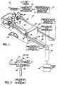
- liquid spray control system is illustrated for use in a liquid spray dispensing system, indicated generally at 12.
- liquid spray dispensing system 12 includes a supply of liquid material 14 that is fluidly connected to a pneumatically controlled regulator 16.
- the regulator 16 controls the fluid pressure of liquid material within dispensing barrel and nozzle 18 of dispenser 19 so that the liquid material may be dispensed in a flat, fan-like spray pattern 20 (Figs. 1 and 8G-8J) onto a substrate (not shown).
- Liquid dispensing system 12 may be a Nordson Model SC105 or SC205 Select Coat Dispensing System manufactured and sold by Nordson Corporation of Westlake. Ohio.
- the barrel and nozzle 18 of the liquid dispensing system is moved in X-Y-Z directions relative to the substrate (not shown) under the control of an X-Y-Z robotic movement platform (not shown) to dispense side-by-side, partially overlapping tracks of liquid material onto a surface of the substrate (not shown), such as in a conformal coating process, to provide a uniformly coated moisture proof barrier on the substrate as is well known in the art.
- liquid spray dispensing system is not limited in any way to liquid dispensing systems for use in a conformal coating process or to liquid dispensing systems that atomize the dispensed liquid. Rather, the term “liquid spray dispensing system” as used herein more broadly refers to any liquid material dispensing system that is operable to dispense liquid material with a predetermined pattern width in a direction toward a substrate.
- the liquid spray control system 10 of the present invention may be used with liquid material dispensers that spray paint, adhesives, sealants or fluxes, by way of example, onto a substrate that is positioned in facing relationship to a dispensing nozzle of the dispensing system.
- the spray pattern dispensed from the liquid dispenser may be atomized or, alternatively, may comprise a continuous band or ribbon of dispensed liquid material, as well as a fibrous web or band of liquid material that emits from a dispensing nozzle with a predetermined pattern width.
- the liquid dispense pattern may be a flat, fan-like pattern as illustrated in the exemplary embodiment described in detail herein or, alternatively, may have an oval, circular, rectangular, square or other cross-section as taken in a plane generally parallel to a plane of the substrate.
- the liquid spray control system 10 of the present invention is particularly adapted to measure and adjust the dispensed pattern of liquid material emitting from the nozzle 18, as well as to measure the alignment of the dispensed liquid material pattern relative to a centerline 22 (Fig. 8A) of the dispensing nozzle 18.
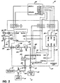
- the liquid spray control system 10 includes an interface unit 24 (Fig. 2) that is electrically and fluidly connected to a sensor fixture 26 (Fig. 1). Interface unit 24 is also fluidly connected to the liquid dispensing system 12 and a source of supply air, and is further electrically coupled to a robot controller 28 (Fig. 2) that is associated with the X-Y-Z robotic movement platform (not shown). More particularly, the sensor fixture 26 includes a drain pan or receptacle 30 made of DELRIN® or similar material that includes a recessed chamber or well 32 for receiving and draining liquid material that is dispensed by the liquid spray dispensing system 12 during the pattern measurement and adjustment procedure as described in detail below.
- a drain pan or receptacle 30 made of DELRIN® or similar material that includes a recessed chamber or well 32 for receiving and draining liquid material that is dispensed by the liquid spray dispensing system 12 during the pattern measurement and adjustment procedure as described in detail below.
- the drain pan 30 has a mounting bracket 34 connected on its lower end that permits the drain pan 30 to be readily mounted through screws (not shown) to a line conveyor (not shown) or other convenient location in the workcell area.
- the drain pan 30 is connected through Nylon® nipples 36 and tubing 38 to a fluid reservoir 40 that is connected to main system vent air through tubing (not shown).
- the liquid spray control system 10 includes a fiber optic emitter 42a mounted on one side wall 44 of the drain pan 30, and a fiber optic receiver 42b mounted in confronting relationship on the opposite side wall 44 of the drain pan 30.
- Suitable fiber optic emitters and receivers are commercially available from Keyence as Part No. FU-77, although other fiber optic emitters and receivers are possible as well.
- the emitter 42a is operable to emit a beam of light that is received by the receiver 42b as is well known in the art.
- Each of the fiber optic emitter and receiver 42a and 42b includes a sensor 46 (Figs. 2 and 3) coupled to a fiber optic cable 48.
- the sensors 46 are threaded into a generally cylindrical sensor shroud 50 (Figs.
- the drain pan 30 includes a pair of upstanding resilient fingers or clips 54 formed in each side wall 44 of the drain pan 30 that are adapted to resiliently engage with an annular recess 56 (Fig. 3) formed on the sensor shroud 50. In this way, the sensor shrouds 50, and their respective sensors 46, may be easily and securely mounted in aligned, confronting relationship on the opposite side walls 44 of the drain pan 30 without tools or adjustment.
- the interface unit 24 of the liquid spray control system 10 includes a fiber optic digital amplifier 58 that is coupled to the fiber optic emitter 42a and receiver 42b through the pair of fiber optic cables 48.
- a suitable fiber optic digital amplifier is commercially available from Keyence as Part No. FS-V1, although other fiber optic digital amplifiers are possible as well.
- Each of the sensor shrouds 50 is fluidly connected to the interface unit 24 through an air purge tubing 60 that extends from a fluid connection fitting 62 on the interface unit 24 to an air purge fitting 64 (Fig. 3) associated with each sensor shroud 50.
- the sensor shrouds 50 each receive regulated supply air from the interface unit 24 so that air flows toward the dispensed liquid pattern 20 (Fig.
- the interface unit 24 receives supply air from a supply air source 70 that is fluidly connected through fitting 72 to the interface unit 24.
- the supply air is fluidly connected to an input 74 of a voltage/pressure regulator 75.
- a suitable voltage/pressure regulator is commercially available from SMC as Part No. ITV2030-31N2L4, although other voltage/pressure regulators are possible as well.
- the supply air is also fluidly connected to the fitting 62 associated with air purge tubing 60 through a regulator 76 and an adjustable needle valve 78.
- the regulator 76 and needle valve 78 permit the purge air pressure supplied to the sensor shrouds 50 to be manually regulated or controlled.
- a pressure gage 80 is provided on the interface unit 24 between the regulator 76 and the needle valve 78 to provide an operator with a readable value of the purge air pressure supplied to the sensor shrouds 50.
- the voltage/pressure regulator 75 is operable to provide a regulated air pressure at its output 82 that is fluidly connected to a three-way solenoid valve 84 and a fitting 86 on the interface unit 24.
- a pressure gage 88 is provided on the interface unit 24 to provide an operator with a readable value of the regulated output air pressure provided by the voltage/pressure regulator 75.
- the pneumatically controlled fluid regulator 16 of the liquid dispensing system 12 is fluidly coupled to the fitting 86 through tubing 90 to receive the regulated air from the voltage/pressure regulator 75.
- the width of the liquid spray pattern 20 dispensed from the nozzle 18 may be readily controlled by varying the air pressure supplied by the voltage/pressure regulator 75 to the pneumatically controlled fluid regulator 16 of the liquid dispensing system 12.
- the regulated output air pressure supplied by the voltage/pressure regulator 75 is controlled through analog voltage input signal 92 received by regulator 75 from a pressure controller 94 of the interface unit 24. More particularly, the pressure controller 94 is the interface between the robot controller 28 and the voltage/pressure regulator 75.
- the pressure controller 94 is operable to receive and interpret digital input signals 96 from the robot controller 28 to increase or decrease the regulated output air pressure supplied from the voltage/pressure regulator 75 to the pneumatically controlled fluid regulator 16.
- the pressure controller 94 converts the digital signals received from the robot controller 28 into the analog signal that is then applied to the voltage/ pressure regulator 75.
- the analog signal which is proportional to the desired pressure setting, is applied to the voltage/pressure regulator 75 and sets the pressure.
- a suitable pressure controller is commercially available from Z-World as Part No. 101-0267, although other pressure controllers are possible as well.
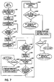
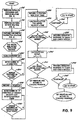
- the robot controller 28 is operable to run the software routines of Figs. 4-7 or alternatively Fig. 9 to perform three functions: 1) automatically adjust the width of the dispensed liquid spray pattern to an operator selected value; 2) automatically measure the width of the liquid spray pattern, compare that value to a predefined acceptable patten width range set by the operator, and provide a warning to the operator if that value falls outside the acceptable range; and 3) automatically measure the offset of the liquid spray pattern relative to the centerline (Fig.
- the software may reside in memory (RAM/ROM) and/or on tape, disc or diskette associated with the robot controller, although the location of the software is not limited to the robot controller 28 as will be appreciated by those of ordinary skill in the art.
- the "INITIALIZE DISPENSER AND SENSOR ROUTINE" 100 will now be described.
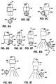
- the purpose of this routine is primarily to positionally associate the centerline 22 (Fig. 8A) of barrel and nozzle 18 with the vertical centerline 102 (Fig. 8A) of the sensors 46.
- the operator moves the barrel and nozzle 18 in X-Y-Z directions through keyboard (not shown) or keypad (not shown) instructions to trigger the sensors 46 (i.e. fiber optic receiver 42b) as shown in Fig. 8B.
- triggering refers to a state of the sensors 46 in which either the light beam transitions from a state of being absent to the fiber optic receiver 42b to a state of being present to the fiber optic receiver 42b, or the light beam transitions from a state of being present to the fiber optic receiver 42b to a state of being absent to the fiber optic receiver 42b. Each of these transitions will cause one of the sensors 46 (fiber optic receiver 42b) to "trigger” and couple a signal to the digital fiber optic amplifier 58.
- the light beam sensitivity of the sensors 46 is adjustable at the digital fiber optic amplifier 58.
- the "FIND BARREL CENTERLINE ROUTINE" 106 is executed. The purpose of this routine is to positionally locate the centerline 22 of barrel and nozzle 18.
- the barrel 18 is moved from the sensor centerline 102 in a +Y direction as shown in Fig. 8C and indicated by arrow 110.
- a determination is made whether a sensor 46 was triggered by a side edge 114a of the barrel 18. If a sensor 46 is not triggered, control passes back to step 108 and the barrel 18 continues to move in the +Y direction from the sensor centerline 102. If, on the other hand, the sensor 46 is triggered by the barrel side edge 114a as shown in Fig. 8C, the +Y position of the sensed barrel edge 114a is recorded at step 116.
- step 118 the barrel 18 is moved in the -Y direction as shown in Fig. 8D and indicated by arrow 120.
- step 128 the barrel 18 is moved so that barrel centerline 22 coincides with the sensor centerline 102 as shown in Fig. 8E.
- step 130 the barrel 18 is moved in the +Z direction as shown in Fig. 8F and indicated by arrow 132.
- step 134 a determination is made whether a sensor 46 has been triggered by barrel end 136. If a sensor 46 has not been triggered by the barrel end 136, control passes back to step 130 and the barrel 18 continues to move in the +Z direction. If a sensor 46 is triggered by the barrel end 136, the +Z position of the barrel end 136 is recorded at step 138.
- the desired air pressure value for the fluid regulator 16 is received from the operator or a preset air pressure is used.
- step 142 the "INITIALIZE DISPENSER AND SENSOR ROUTINE" is complete and control passes over to the "PATTERN SETTING ROUTINE" 144 of Fig. 5.
- the purpose of the "PATTERN SETTING ROUTINE” 144 is to set the desired fan width ("FW”) and fan height ("FH") desired by the operator. To this end, as shown in Fig. 5, at step 146, of the "PATTERN SETTING ROUTINE” 144, the fan width ("FW") and the fan height (“FH") values are received from the operator. At step 148, the "PATTERN SETTING ROUTINE” 144 is complete and control passes over to the "FAN WIDTH CALIBRATION ROUTINE" 150 shown in Fig. 6.
- the purpose of the "FAN WIDTH CALIBRATION ROUTINE” 150 is to automatically adjust the actual width of the fan to the programmed fan width ("FW") value.
- the barrel 18 is moved in the +Z direction to fan height ("FH") as shown in Fig. 8G.
- the barrel 18 is moved in the -Y direction to a -Y position corresponding to"FW"/2 as shown in Fig. 8G.
- the air pressure value to the fluid regulator 16 is set with either the operator selected value or the preset air pressure value.
- the dispenser 19 is turned on.
- a determination is made whether a sensor 46 has been triggered by a fan spray edge 162.
- step 164 increases the air pressure supplied to fluid regulator 16 in 2 PSI increments to increase the fan width ("FW") as indicated by arrow 166.
- the increase in air pressure of fluid regulator 16 results from electrical signals being coupled from the amplifier 58 to robot controller 28 which provides digital input signals 96 to the pressure controller 94.
- the pressure controller 94 converts the digital input signals 96 to the analog signal 92 that is applied to the voltage/pressure regulator 75 as described in detail above.
- a determination is made whether a sensor 46 was triggered by fan spray edge 162, thereby indicating that a properly adjusted fan width ("FW") has been set. If yes, the dispenser 19 is turned off at step 168.
- the purpose of the "FAN WIDTH AND OFFSET DETECTION ROUTINE” 178 is to automatically measure the actual fan width ("FW") and offset of the fan pattern relative to the barrel centerline 22.
- the dispenser 19 is turned on.
- the barrel 18 is moved in the +Y direction as indicated by the arrow 184 in Fig. 8G.
- a determination is made whether a sensor 46 was triggered by a fan spray edge 162. If the sensor 46 is not triggered, control passes back to step 182 and the barrel 18 continues to move in the +Y direction, If the sensor 46 is triggered by the fan spray edge 162, as occurs in Fig. 8H, the +Y position of the barrel 18 is recorded at step 188.
- step 190 the barrel 18 is moved in the -Y direction as indicated by arrow 191 in Fig. 8H.
- step 196 the actual fan width is calculated as the difference of the stored +Y and -Y values.
- step 210 a determination is made whether the operator wants to continue at step 210. If not, control passes back to "START.” Otherwise, the pressure is set and control is returned to the coating program. If a determination is made at step 206 that the fan offset is within an acceptable range, the pressure is set and control is also passed to the coating program.
- an alternative software program is shown for execution by the liquid spray control system 10.
- the "INITIALIZE DISPENSER AND SENOR ROUTINE” is performed as described in detail above in relation to Fig. 4.
- the "PATTERN SETTING ROUTINE” is performed as described in detail above in relation to Fig. 5.
- the "FAN WIDTH CALIBRATION ROUTINE” is performed as described in detail above in relation to Fig. 6.
- the dispenser 19 is turned on. Barrel 18 is then moved in the +Y direction at step 222 as shown in Fig. 8G and represented by arrow 184.
- control passes to step 232 and the -Y position of the barrel 18 is recorded and the timer is stopped.
- the actual fan width is calculated as the product of the known velocity and the elapsed time established by the timer.
- liquid dispenser system 12 is responsive to air pressure supplied by the voltage/pressure regulator 75, those skilled in the art will readily appreciate the multitude of other regulator devices that could be substituted in the present invention for controlling the fluid pressure within the liquid dispensing system 12.
- the liquid spray control system 10 of the present invention automatically performs the function of adjusting the width of the spray pattern 20 to the value set by the operator. For example, if the fan width is initially too narrow, the liquid spray control system 10 incrementally increases the air pressure supplied to the fluid regulator 16 to widen the fan width as indicated by arrow 166 in Fig. 8G. On the other hand, if the fan width is initially too wide, the liquid spray control system 10 automatically decreases the fan width to the preset value by incrementally decreasing the air pressure supplied to the fluid regulator 16 to thereby narrow the fan width as indicated by arrow 174 in Fig. 8G.
- the liquid spray control system 10 automatically measures the actual fan width and determines whether the actual fan width falls within an acceptable range. In this way, if the actual fan width falls outside of the acceptable range, the operator is automatically given a warning and a decision on whether to continue. Thus, a wasteful coating production run is avoided. Additionally, the liquid spray control system 10 automatically measures the offset of the fan pattern relative to the centerline 22 of the barrel 18. If the measured offset is outside an acceptable, the operator is also given a warning and a decision on whether to continue with the coating process. Thus, the liquid spray control system 10 of the present invention improves width control of a dispensed liquid pattern. The liquid spray control system 10 also improves the operator's ability to readily identify problems in the dispensed liquid spray pattern. Moreover, the liquid spray control system 10 of the present invention improves the operator's ability to adjust the width of the liquid spray pattern to accommodate for variations on liquid material viscosities and pressures.
Landscapes
- Spray Control Apparatus (AREA)
- Nozzles (AREA)
Abstract
Description
Claims (35)
- A method of measuring the width of a liquid spray pattern having a first and second edge using a liquid dispenser having a centerline, a first edge and a second opposite edge and a sensor, comprising:dispensing the liquid spray pattern from the liquid dispenser;moving the liquid spray pattern in one direction relative to the sensor;detecting the first edge of the liquid spray pattern with the sensor;associating the detected liquid spray pattern first edge with a first position;moving the liquid spray pattern in an opposite direction relative to the sensor;detecting the second edge of the liquid spray pattern with the sensor;associating the detected liquid spray pattern second edge with a second position; andcalculating the width of the liquid spray pattern using the first and second positions.
- The method of claim 1 further comprising the steps of:determining a position of the sensor;determining a position of the dispenser centerline;associating the position of the dispenser centerline with the position the sensor; andcalculating an offset of the liquid spray pattern relative to the dispenser centerline using the first and second positions.
- The method of claim 2 wherein the step of determining the position of the dispenser centerline comprises:moving the dispenser in one direction relative to the sensor;detecting the first edge of the dispenser with the sensor;associating the detected dispenser first edge with a third position;moving the dispenser in an opposite direction relative to the sensor;detecting the second opposite edge of the dispenser with the sensor;associating the detected dispenser second opposite edge with a fourth position; andcalculating the position of the dispenser centerline using the third and fourth positions.
- The method of claim 1 wherein the step of detecting the first edge of the liquid spray pattern comprises:transmitting a beam of light;moving the liquid spray pattern through the beam of light; andgenerating a signal in response to one of the presence or absence of the liquid spray pattern first edge within the beam of light.
- The method of claim 4 wherein the step of detecting the second edge of the liquid spray pattern comprises:continuing to move the liquid spray pattern through the beam of light; andgenerating a signal in response to one of the presence or absence of the liquid spray pattern second edge within the beam of light.
- A method of measuring the width of a liquid spray pattern having a first and second edge using a liquid dispenser having a centerline, a first edge and a second opposite edge, a sensor and a timer, comprising:dispensing the liquid spray pattern from the liquid dispenser;moving the liquid spray pattern in one direction relative to the sensor;detecting the first edge of the liquid spray pattern with the sensor;initiating the timer upon detecting the first edge of the liquid spray pattern;moving the liquid spray pattern at a constant velocity in an opposite direction relative to the sensor;detecting the second edge of the liquid spray pattern with the sensor;terminating the timer upon detecting the second edge of the liquid spray pattern;determining the elapsed time between said initiation of the timer and said termination of the timer; andcalculating a width of the liquid spray pattern using the elapsed time and the constant velocity.
- The method of claim 6 further comprising the steps of:associating the detected liquid spray pattern first edge with a first position;associating the detected liquid spray pattern second edge with a second position;determining a position of the sensor;determining a position of the dispenser centerline;associating the position of the dispenser centerline with the position of the sensor; andcalculating an offset of the liquid spray pattern relative to the dispenser centerline using the first and second positions.
- The method of claim 7 wherein the step of determining the position of the dispenser centerline comprises:moving the dispenser in one direction relative to the sensor;detecting the first edge of the dispenser with the sensor;associating the detected dispenser first edge with a third position;moving the dispenser in an opposite direction relative to the sensor;detecting the second opposite edge of the dispenser with the sensor;associating the detected dispenser second opposite edge with a fourth position; andcalculating the position of the dispenser centerline using the third and fourth positions.
- The method of claim 8 wherein the step of detecting the first edge of the liquid spray pattern comprises:transmitting a beam of light;moving the liquid spray pattern through the beam of light; andgenerating a signal in response to one of the presence or absence of the liquid spray pattern first edge within the beam of light.
- The method of claim 9 wherein the step of detecting the second edge of the liquid spray pattern comprises:continuing to move the liquid spray pattern through the beam of light; andgenerating a signal in response to one of the presence or absence of the liquid spray pattern second edge within the beam of light.
- A method of adjusting the width of a liquid spray pattern using a liquid dispenser and a sensor, comprising:positioning the liquid dispenser at a predetermined position relative to the sensor;dispensing the liquid spray pattern from the liquid dispenser at a predetermined dispensing pressure;detecting an absence of the liquid spray pattern with the sensor;increasing the width of the liquid spray pattern by increasing the dispensing pressure until the liquid spray pattern is detected by the sensor.
- A method of adjusting the width of a liquid spray pattern using a liquid dispenser and a sensor, comprising:positioning the liquid dispenser at a predetermined position relative to the sensor;dispensing the liquid spray pattern from the liquid dispenser at a predetermined dispensing pressure;detecting a presence of the liquid spray pattern with the sensor;decreasing the width of the liquid spray pattern by decreasing the dispensing pressure until an absence of the liquid spray pattern is detected by the sensor.
- A liquid dispensing system for dispensing a variable width liquid spray pattern having a first and second edge, comprising:a source of liquid material;a dispensing nozzle connected to said source of liquid material and capable of dispensing said liquid material as a liquid spray pattern with a predetermined spray pattern width;a pressure regulator operatively coupled to said source of liquid material and said dispensing nozzle to regulate a pressure at which said liquid material is dispensed by said dispensing nozzle; anda control circuit coupled to said pressure regulator and capable of varying the regulated pressure at which said liquid material is dispensed by said dispensing nozzle to increase or decrease the width of the liquid spray pattern.
- The liquid dispensing system of claim 13 further comprising a source of air operatively connected to said control circuit, wherein said pressure regulator comprises a pneumatically controlled fluid regulator having an air inlet coupled to said source of air and capable of increasing or decreasing the pressure at which said liquid material is dispensed by said dispensing nozzle by varying a pressure of air at said air inlet.
- The liquid dispensing system of claim 14 wherein said control circuit is capable of varying the pressure of air at said air inlet of said pneumatically controlled fluid regulator to increase or decrease the pressure at which said liquid material is dispensed by said dispensing nozzle.
- The liquid dispensing system of claim 14 further comprising a sensor coupled to said control circuit and capable of detecting one of the presence or absence of the first edge and second edge of the liquid spray pattern.
- The liquid dispensing system of claim 16 wherein said sensor is capable of applying a signal to said control circuit in response to detecting one of the presence or absence of at least one of the first edge and second edge, and further wherein said control circuit is capable of varying the regulated pressure at which said liquid material is dispensed by said dispensing nozzle in response to receipt of said signal to increase or decrease the width of the liquid spray pattern.
- The liquid dispensing system of claim 17 wherein said sensor comprises a light beam emitter and a light beam receiver.
- The liquid dispensing system of claim 16 further comprising a fluid receptacle defined by a bottom wall, a pair of upstanding side walls and a pair of upstanding end walls and capable of receiving said liquid material dispensed from said dispensing nozzle, each of said side walls having a pair of resilient retaining members capable of releasably engaging therebetween said sensor.
- The liquid dispensing system of claim 19 wherein each of said pair of resilient retaining members are formed in each of said fluid receptacle side walls.
- The liquid dispensing system of claim 16 further comprising a shroud member mounted about said sensor to form an annular chamber thereabout, said shroud member having an air inlet connected to said annular chamber and to said source of air and being capable of emitting air toward the liquid spray pattern.
- A method of measuring a liquid spray pattern, comprising:dispensing a liquid spray pattern from a liquid dispenser;moving said liquid spray pattern in one direction relative to a sensor;detecting one edge of said liquid spray pattern with said sensor and associating said detected liquid spray edge with a first position;moving said liquid spray pattern in an opposite direction relative to said sensor;detecting an opposite edge of said liquid spray pattern with said sensor and associating said detected opposite liquid spray edge with a second position; andcalculating a width of said liquid spray pattern from said first and second positions.
- The method of claim 22 further comprising the steps of:determining a dispenser centerline position;associating said dispenser centerline position with a position of said sensor; andcalculating an offset of said liquid spray pattern relative to said dispenser centerline from said first and second positions.
- The method of claim 23 wherein the step of determining said dispenser centerline position comprises:moving said dispenser in one direction relative to said sensor;detecting one side edge of said dispenser with said sensor and associating said detected dispenser side edge with a third position;moving said dispenser in an opposite direction relative to said dispenser;detecting an opposite side edge of said dispenser with said sensor and associating said detected opposite dispenser side edge with a fourth position; andcalculating a dispenser centerline position from said third and fourth positions.
- The method of claim 22 wherein the step of detecting one edge of said liquid spray pattern comprises:transmitting a beam of light;moving one of said liquid spray pattern edges through said beam of light; andgenerating a signal in response to the presence or absence of said liquid spray pattern edge within said beam of light.
- A method of measuring a liquid spray pattern, comprising:dispensing a liquid spray pattern from a liquid dispenser;moving said liquid spray pattern in one direction relative to a sensor at a constant velocity;detecting one edge of said liquid spray pattern with said sensor and associating said detected liquid spray edge with a first position;initiating a timer upon detecting said one edge of said liquid spray pattern;detecting an opposite edge of said liquid spray pattern with said sensor and associating said detected opposite liquid spray edge with a second position;terminating said timer upon detecting said opposite edge of said liquid spray pattern;determining an elapsed time between the initiation and termination of said timer; andcalculating a width of said liquid spray pattern from said elapsed time and said constant velocity.
- The method of claim 26 further comprising the steps of:determining a dispenser centerline position;associating said dispenser centerline position with a position of said sensor; andcalculating an offset of said liquid spray pattern relative to said dispenser centerline from said first and second positions.
- The method of claim 27 wherein the step of determining said dispenser centerline position comprises:moving said dispenser in one direction relative to said sensor;detecting one side edge of said dispenser with said sensor and associating said detected dispenser side edge with a third position;moving said dispenser in an opposite direction relative to said dispenser;detecting an opposite side edge of said dispenser with said sensor and associating said detected opposite dispenser side edge with a fourth position; andcalculating a dispenser centerline position from said third and fourth positions.
- The method of claim 26 wherein the step of detecting one edge of said liquid spray pattern comprises:transmitting a beam of light;moving one of said liquid spray pattern edges through said beam of light; andgenerating a signal in response to the presence or absence of said liquid spray pattern edge within said beam of light.
- A method of adjusting a liquid spray pattern, comprising:positioning a liquid dispenser at a predetermined position relative to a sensor;dispensing a liquid spray pattern from said liquid dispenser;detecting an absence of one edge of said liquid spray pattern with said sensor;increasing a width of said liquid spray pattern until a presence of said one edge of said liquid spray pattern is detected by said sensor.
- The method of claim 30 wherein said dispensing step includes dispensing said liquid spray pattern at a predetermined fluid pressure.
- The method of claim 31 wherein said liquid spray pattern width increasing step includes increasing said fluid pressure until a presence of said one edge of said liquid spray pattern is detected by said sensor.
- A method of adjusting a liquid spray pattern, comprising:positioning a liquid dispenser at a predetermined position relative to a sensor;dispensing a liquid spray pattern from said liquid dispenser;detecting a presence of one edge of said liquid spray pattern with said sensor;decreasing a width of said liquid spray pattern until an absence of said one edge of said liquid spray pattern is detected by said sensor.
- The method of claim 33 wherein said dispensing step includes dispensing said liquid spray pattern at a predetermined fluid pressure.
- The method of claim 34 wherein said liquid spray pattern width decreasing step includes decreasing said fluid pressure until an absence of said one edge of said liquid spray pattern is detected by said sensor.
Applications Claiming Priority (2)
| Application Number | Priority Date | Filing Date | Title |
|---|---|---|---|
| US15241399P | 1999-09-03 | 1999-09-03 | |
| US152413P | 1999-09-03 |
Publications (3)
| Publication Number | Publication Date |
|---|---|
| EP1080787A2 true EP1080787A2 (en) | 2001-03-07 |
| EP1080787A3 EP1080787A3 (en) | 2004-11-24 |
| EP1080787B1 EP1080787B1 (en) | 2008-02-20 |
Family
ID=22542816
Family Applications (1)
| Application Number | Title | Priority Date | Filing Date |
|---|---|---|---|
| EP00119124A Expired - Lifetime EP1080787B1 (en) | 1999-09-03 | 2000-09-04 | Method and apparatus for measuring and adjusting a liquid spray pattern |
Country Status (3)
| Country | Link |
|---|---|
| US (1) | US6457655B1 (en) |
| EP (1) | EP1080787B1 (en) |
| DE (1) | DE60038080T2 (en) |
Cited By (4)
| Publication number | Priority date | Publication date | Assignee | Title |
|---|---|---|---|---|
| EP1432526A4 (en) * | 2002-01-22 | 2005-04-20 | Nordson Corp | Method and apparatus for detecting a liquid spray pattern |
| EP3216526A1 (en) * | 2016-03-11 | 2017-09-13 | Precision Valve & Automation, Inc. | Automatically controlling a liquid spray pattern |
| WO2018153997A1 (en) * | 2017-02-24 | 2018-08-30 | Vermes Microdispensing GmbH | Guide system for detection devices |
| RU2712974C1 (en) * | 2016-04-25 | 2020-02-03 | Рем Термал Системз Гмбх | Device and method of measuring lacquer jet for varnishing of printed-circuit plates |
Families Citing this family (20)
| Publication number | Priority date | Publication date | Assignee | Title |
|---|---|---|---|---|
| US7107129B2 (en) | 2002-02-28 | 2006-09-12 | Oshkosh Truck Corporation | Turret positioning system and method for a fire fighting vehicle |
| US7162332B2 (en) * | 1999-07-30 | 2007-01-09 | Oshkosh Truck Corporation | Turret deployment system and method for a fire fighting vehicle |
| US7729831B2 (en) | 1999-07-30 | 2010-06-01 | Oshkosh Corporation | Concrete placement vehicle control system and method |
| US7184862B2 (en) | 1999-07-30 | 2007-02-27 | Oshkosh Truck Corporation | Turret targeting system and method for a fire fighting vehicle |
| US7127331B2 (en) * | 1999-07-30 | 2006-10-24 | Oshkosh Truck Corporation | Turret operator interface system and method for a fire fighting vehicle |
| US7277782B2 (en) | 2001-01-31 | 2007-10-02 | Oshkosh Truck Corporation | Control system and method for electric vehicle |
| NL1024402C2 (en) * | 2003-09-30 | 2005-03-31 | Lely Entpr Ag | Device and method for applying a fluid to a teat of a dairy animal. |
| US7143654B2 (en) * | 2003-12-11 | 2006-12-05 | Massachusetts Institute Of Technology | Methods and apparatus for detecting the presence, intensity, trajectory or location of a liquid stream |
| US6962070B1 (en) * | 2004-04-28 | 2005-11-08 | Spraying Systems Co. | Apparatus and method for measuring characteristics of fluid spray patterns |
| US8154711B1 (en) | 2004-10-01 | 2012-04-10 | Ingo Werner Scheer | Spray diagnostic and control method and system |
| US7792611B2 (en) * | 2004-10-01 | 2010-09-07 | Ingo Werner Scheer | Spray pattern characterization and monitoring method and system |
| US20070088469A1 (en) * | 2005-10-04 | 2007-04-19 | Oshkosh Truck Corporation | Vehicle control system and method |
| US20080011333A1 (en) * | 2006-07-13 | 2008-01-17 | Rodgers Michael C | Cleaning coating dispensers |
| DE102007062132A1 (en) * | 2007-12-21 | 2009-07-02 | Dürr Systems GmbH | Test method and test device for functional testing of a painting device |
| US8448377B1 (en) * | 2008-05-09 | 2013-05-28 | Hampton Harold Price, III | Closed-circuit pest extermination system |
| JP6122271B2 (en) * | 2012-10-17 | 2017-04-26 | アルファーデザイン株式会社 | Liquid ejection device, spray pattern width measuring method, program |
| JP6864680B2 (en) * | 2015-11-04 | 2021-04-28 | ノードソン コーポレーションNordson Corporation | Methods and systems for controlling the fluid pattern of dispense fluids |
| US10712187B2 (en) | 2018-02-19 | 2020-07-14 | Cnh Industrial America Llc | Spray pattern monitoring system |
| CN112275483A (en) * | 2020-09-07 | 2021-01-29 | 惠州市德赛西威汽车电子股份有限公司 | Multifunctional three-proofing paint coating equipment and control method thereof |
| EP4359146A2 (en) * | 2021-06-24 | 2024-05-01 | Nordson Corporation | Non-contact ultrasonic nozzle cleaner with closed-loop automatic clog detection |
Family Cites Families (10)
| Publication number | Priority date | Publication date | Assignee | Title |
|---|---|---|---|---|
| DE2514612A1 (en) * | 1975-04-03 | 1976-10-07 | Asbrand Rudolf | Continuous contactless measurement method apparatus - determines thickness of esp. extruded products, using radiation beam partially interrupted by measured object |
| US4346849A (en) | 1976-07-19 | 1982-08-31 | Nordson Corporation | Airless spray nozzle and method of making it |
| US4349947A (en) | 1980-09-29 | 1982-09-21 | Nordson Corporation | Method for manufacturing an airless spray nozzle |
| US5017409A (en) | 1988-06-13 | 1991-05-21 | Union Carbide Chemicals And Plastics Technology Corporation | Method of conformal coating |
| CA2052699A1 (en) | 1990-10-19 | 1992-04-20 | Stephen L. Merkel | Method and apparatus for monitoring parameters of coating material dispensing systems and processes by analysis of swirl pattern dynamics |
| US5208064A (en) | 1991-11-04 | 1993-05-04 | Nordson Corporation | Method and apparatus for optically monitoring and controlling a moving fiber of material |
| CA2098784A1 (en) | 1992-07-08 | 1994-01-09 | Bentley Boger | Apparatus and methods for applying conformal coatings to electronic circuit boards |
| US5316219A (en) * | 1992-07-08 | 1994-05-31 | Nordson Corporation | Coating apparatus with pattern width control |
| DE19727484C2 (en) * | 1997-06-27 | 2001-02-08 | Sensor Instr Gmbh | Method and device for measuring a spray jet emerging from a spray nozzle |
| IT1296419B1 (en) * | 1997-11-28 | 1999-06-25 | Procomac Spa | PROCEDURE AND DEVICE FOR THE CONTROL OF NOZZLES, IN PARTICULAR FOR SPRAY NOZZLES IN THE RINSING MACHINE. |
-
2000
- 2000-09-01 US US09/654,404 patent/US6457655B1/en not_active Expired - Lifetime
- 2000-09-04 EP EP00119124A patent/EP1080787B1/en not_active Expired - Lifetime
- 2000-09-04 DE DE60038080T patent/DE60038080T2/en not_active Expired - Lifetime
Cited By (9)
| Publication number | Priority date | Publication date | Assignee | Title |
|---|---|---|---|---|
| EP1432526A4 (en) * | 2002-01-22 | 2005-04-20 | Nordson Corp | Method and apparatus for detecting a liquid spray pattern |
| US7188781B2 (en) | 2002-01-22 | 2007-03-13 | Nordson Corporation | Method and apparatus for detecting a liquid spray pattern |
| CN100509176C (en) * | 2002-01-22 | 2009-07-08 | 诺德森公司 | Method and apparatus for detecting a liquid spray pattern |
| EP3216526A1 (en) * | 2016-03-11 | 2017-09-13 | Precision Valve & Automation, Inc. | Automatically controlling a liquid spray pattern |
| US10562054B2 (en) | 2016-03-11 | 2020-02-18 | Precision Valve & Automation, Inc. | Automatically controlling a liquid spray pattern |
| US11938498B2 (en) | 2016-03-11 | 2024-03-26 | Precision Valve & Automation, Inc. | Automatically controlling a liquid spray pattern |
| RU2712974C1 (en) * | 2016-04-25 | 2020-02-03 | Рем Термал Системз Гмбх | Device and method of measuring lacquer jet for varnishing of printed-circuit plates |
| US11524310B2 (en) | 2016-04-25 | 2022-12-13 | Rehm Thermal Systems Gmbh | Device and method for measuring a varnish jet for varnishing circuit boards |
| WO2018153997A1 (en) * | 2017-02-24 | 2018-08-30 | Vermes Microdispensing GmbH | Guide system for detection devices |
Also Published As
| Publication number | Publication date |
|---|---|
| DE60038080D1 (en) | 2008-04-03 |
| EP1080787B1 (en) | 2008-02-20 |
| US6457655B1 (en) | 2002-10-01 |
| DE60038080T2 (en) | 2009-03-05 |
| EP1080787A3 (en) | 2004-11-24 |
Similar Documents
| Publication | Publication Date | Title |
|---|---|---|
| US6457655B1 (en) | Method and apparatus for measuring and adjusting a liquid spray pattern | |
| US7188781B2 (en) | Method and apparatus for detecting a liquid spray pattern | |
| US6348098B1 (en) | Flow controller | |
| US9393586B2 (en) | Dispenser and method of dispensing and controlling with a flow meter | |
| US9847265B2 (en) | Flow metering for dispense monitoring and control | |
| US11938498B2 (en) | Automatically controlling a liquid spray pattern | |
| JP2834817B2 (en) | Powdering equipment | |
| JP3731616B2 (en) | Coating apparatus and coating method, and color filter manufacturing apparatus and manufacturing method | |
| WO2017048688A1 (en) | Dispense monitoring and control | |
| CN100478967C (en) | Methods for regulating the placement of fluid dispensed from an applicator onto a workpiece | |
| JP4772180B2 (en) | Method and apparatus for measuring and adjusting a liquid spray pattern | |
| JP2003033687A (en) | Automatic flow controller for paint supply air pump | |
| JP2002361147A (en) | Viscous liquid coating device | |
| JPH079454U (en) | Control device for spray coating amount | |
| JPH05104050A (en) | Device for controlling flow rate of high viscosity material | |
| JPH04271861A (en) | Painting robot device | |
| JPS62106869A (en) | Color matching method | |
| JP2000051764A (en) | Pattern coating system |
Legal Events
| Date | Code | Title | Description |
|---|---|---|---|
| PUAI | Public reference made under article 153(3) epc to a published international application that has entered the european phase |
Free format text: ORIGINAL CODE: 0009012 |
|
| AK | Designated contracting states |
Kind code of ref document: A2 Designated state(s): AT BE CH CY DE DK ES FI FR GB GR IE IT LI LU MC NL PT SE |
|
| AX | Request for extension of the european patent |
Free format text: AL;LT;LV;MK;RO;SI |
|
| PUAL | Search report despatched |
Free format text: ORIGINAL CODE: 0009013 |
|
| AK | Designated contracting states |
Kind code of ref document: A3 Designated state(s): AT BE CH CY DE DK ES FI FR GB GR IE IT LI LU MC NL PT SE |
|
| AX | Request for extension of the european patent |
Extension state: AL LT LV MK RO SI |
|
| 17P | Request for examination filed |
Effective date: 20050524 |
|
| AKX | Designation fees paid |
Designated state(s): DE FR GB |
|
| 17Q | First examination report despatched |
Effective date: 20060728 |
|
| GRAP | Despatch of communication of intention to grant a patent |
Free format text: ORIGINAL CODE: EPIDOSNIGR1 |
|
| GRAS | Grant fee paid |
Free format text: ORIGINAL CODE: EPIDOSNIGR3 |
|
| GRAA | (expected) grant |
Free format text: ORIGINAL CODE: 0009210 |
|
| AK | Designated contracting states |
Kind code of ref document: B1 Designated state(s): DE FR GB |
|
| REG | Reference to a national code |
Ref country code: GB Ref legal event code: FG4D |
|
| REF | Corresponds to: |
Ref document number: 60038080 Country of ref document: DE Date of ref document: 20080403 Kind code of ref document: P |
|
| ET | Fr: translation filed | ||
| PLBE | No opposition filed within time limit |
Free format text: ORIGINAL CODE: 0009261 |
|
| STAA | Information on the status of an ep patent application or granted ep patent |
Free format text: STATUS: NO OPPOSITION FILED WITHIN TIME LIMIT |
|
| 26N | No opposition filed |
Effective date: 20081121 |
|
| REG | Reference to a national code |
Ref country code: FR Ref legal event code: PLFP Year of fee payment: 17 |
|
| REG | Reference to a national code |
Ref country code: FR Ref legal event code: PLFP Year of fee payment: 18 |
|
| REG | Reference to a national code |
Ref country code: FR Ref legal event code: PLFP Year of fee payment: 19 |
|
| PGFP | Annual fee paid to national office [announced via postgrant information from national office to epo] |
Ref country code: DE Payment date: 20190918 Year of fee payment: 20 Ref country code: FR Payment date: 20190925 Year of fee payment: 20 |
|
| PGFP | Annual fee paid to national office [announced via postgrant information from national office to epo] |
Ref country code: GB Payment date: 20190920 Year of fee payment: 20 |
|
| REG | Reference to a national code |
Ref country code: DE Ref legal event code: R071 Ref document number: 60038080 Country of ref document: DE |
|
| REG | Reference to a national code |
Ref country code: GB Ref legal event code: PE20 Expiry date: 20200903 |
|
| PG25 | Lapsed in a contracting state [announced via postgrant information from national office to epo] |
Ref country code: GB Free format text: LAPSE BECAUSE OF EXPIRATION OF PROTECTION Effective date: 20200903 |