EP1080706A1 - Laser treatment apparatus - Google Patents
Laser treatment apparatus Download PDFInfo
- Publication number
- EP1080706A1 EP1080706A1 EP00118775A EP00118775A EP1080706A1 EP 1080706 A1 EP1080706 A1 EP 1080706A1 EP 00118775 A EP00118775 A EP 00118775A EP 00118775 A EP00118775 A EP 00118775A EP 1080706 A1 EP1080706 A1 EP 1080706A1
- Authority
- EP
- European Patent Office
- Prior art keywords
- optical system
- sighting
- laser
- treatment
- aiming
- Prior art date
- Legal status (The legal status is an assumption and is not a legal conclusion. Google has not performed a legal analysis and makes no representation as to the accuracy of the status listed.)
- Granted
Links
- 238000013532 laser treatment Methods 0.000 title claims abstract description 36
- 238000011282 treatment Methods 0.000 claims abstract description 87
- 230000003287 optical effect Effects 0.000 claims abstract description 75
- 238000012545 processing Methods 0.000 claims abstract description 27
- 238000001514 detection method Methods 0.000 claims abstract description 19
- 230000001678 irradiating effect Effects 0.000 claims abstract description 15
- 238000003384 imaging method Methods 0.000 claims abstract description 3
- 238000000034 method Methods 0.000 description 7
- 230000007246 mechanism Effects 0.000 description 5
- 238000005286 illumination Methods 0.000 description 3
- 239000000284 extract Substances 0.000 description 2
- 230000004907 flux Effects 0.000 description 2
- 238000012986 modification Methods 0.000 description 2
- 230000004048 modification Effects 0.000 description 2
- 230000000649 photocoagulation Effects 0.000 description 2
- 239000004065 semiconductor Substances 0.000 description 2
- 206010036346 Posterior capsule opacification Diseases 0.000 description 1
- 208000017442 Retinal disease Diseases 0.000 description 1
- 208000020221 Short stature Diseases 0.000 description 1
- 230000002159 abnormal effect Effects 0.000 description 1
- 239000002775 capsule Substances 0.000 description 1
- 230000008859 change Effects 0.000 description 1
- ZPUCINDJVBIVPJ-LJISPDSOSA-N cocaine Chemical compound O([C@H]1C[C@@H]2CC[C@@H](N2C)[C@H]1C(=O)OC)C(=O)C1=CC=CC=C1 ZPUCINDJVBIVPJ-LJISPDSOSA-N 0.000 description 1
- 238000013461 design Methods 0.000 description 1
- 230000000694 effects Effects 0.000 description 1
- 239000000835 fiber Substances 0.000 description 1
- 239000013307 optical fiber Substances 0.000 description 1
- 230000010355 oscillation Effects 0.000 description 1
- 230000010287 polarization Effects 0.000 description 1
- 230000001681 protective effect Effects 0.000 description 1
- 230000035939 shock Effects 0.000 description 1
- 238000012360 testing method Methods 0.000 description 1
Images



Classifications
-
- A—HUMAN NECESSITIES
- A61—MEDICAL OR VETERINARY SCIENCE; HYGIENE
- A61F—FILTERS IMPLANTABLE INTO BLOOD VESSELS; PROSTHESES; DEVICES PROVIDING PATENCY TO, OR PREVENTING COLLAPSING OF, TUBULAR STRUCTURES OF THE BODY, e.g. STENTS; ORTHOPAEDIC, NURSING OR CONTRACEPTIVE DEVICES; FOMENTATION; TREATMENT OR PROTECTION OF EYES OR EARS; BANDAGES, DRESSINGS OR ABSORBENT PADS; FIRST-AID KITS
- A61F9/00—Methods or devices for treatment of the eyes; Devices for putting in contact-lenses; Devices to correct squinting; Apparatus to guide the blind; Protective devices for the eyes, carried on the body or in the hand
- A61F9/007—Methods or devices for eye surgery
- A61F9/008—Methods or devices for eye surgery using laser
-
- A—HUMAN NECESSITIES
- A61—MEDICAL OR VETERINARY SCIENCE; HYGIENE
- A61B—DIAGNOSIS; SURGERY; IDENTIFICATION
- A61B18/00—Surgical instruments, devices or methods for transferring non-mechanical forms of energy to or from the body
- A61B18/18—Surgical instruments, devices or methods for transferring non-mechanical forms of energy to or from the body by applying electromagnetic radiation, e.g. microwaves
- A61B18/20—Surgical instruments, devices or methods for transferring non-mechanical forms of energy to or from the body by applying electromagnetic radiation, e.g. microwaves using laser
- A61B2018/2015—Miscellaneous features
- A61B2018/2025—Miscellaneous features with a pilot laser
-
- A—HUMAN NECESSITIES
- A61—MEDICAL OR VETERINARY SCIENCE; HYGIENE
- A61F—FILTERS IMPLANTABLE INTO BLOOD VESSELS; PROSTHESES; DEVICES PROVIDING PATENCY TO, OR PREVENTING COLLAPSING OF, TUBULAR STRUCTURES OF THE BODY, e.g. STENTS; ORTHOPAEDIC, NURSING OR CONTRACEPTIVE DEVICES; FOMENTATION; TREATMENT OR PROTECTION OF EYES OR EARS; BANDAGES, DRESSINGS OR ABSORBENT PADS; FIRST-AID KITS
- A61F9/00—Methods or devices for treatment of the eyes; Devices for putting in contact-lenses; Devices to correct squinting; Apparatus to guide the blind; Protective devices for the eyes, carried on the body or in the hand
- A61F9/007—Methods or devices for eye surgery
- A61F9/008—Methods or devices for eye surgery using laser
- A61F2009/00844—Feedback systems
- A61F2009/00846—Eyetracking
Definitions
- the present invention relates to a laser treatment apparatus for irradiating an affected part of a patient's eye with a treatment laser beam.
- a laser treatment apparatus for irradiating an affected part of the patient's eye with a treatment laser beam of pulse wave.
- the apparatus of this kind is designed to vaporize and crush the tissue of the affected part by focusing the treatment laser beam on a desired point (an area to be treated) of the affected part, thereby forming plasma to generate shock waves. Accordingly, the importance is to precisely focus the treatment laser beam on the desired point.
- a laser treatment apparatus for irradiating an affected part of a patient's eye with a treatment laser beam of continuous wave.
- the apparatus of this type is designed so that a visible aiming beam is irradiated to focus on a desired point which is the same as a focus point of the treatment laser beam to form an image with the minimum spot diameter, whereby the treatment laser beam is precisely focused on the desired point.
- the focusing of the aiming beam on the desired point to ensure the focusing of the treatment laser beam thereon is also referred to as "sighting".
- the sighting is performed by an operator while observing the coincident state of the two aiming beams (the overlapping condition of the two images of the aiming beams) or the focusing condition of the aiming beam (the spot diameter of the image of the aiming beam) through eyepieces of a microscopic section of the apparatus. This would cause a difficulty for low-skilled operators in judging the propriety of the sighting. Furthermore, differences among operators may be included in determinations about the propriety of the sighting.
- the present invention has been made in view of the above circumstances and has an object to overcome the above problems and to provide a laser treatment apparatus which allows an operator to easily observe a patient's eye and to precisely easily perform sighting in order to focus a treatment laser beam on a desired point.
- a laser treatment apparatus for irradiating an affected part of a patient's eye with a treatment laser beam to treat the affected part, including: treatment beam irradiation means including a first irradiation optical system for irradiating the treatment beam; aiming beam irradiation means including a second irradiation optical system for irradiating an aiming beam, the second irradiation optical system being optically adjusted such that sighting of the treatment beam is completed when the aiming beam forms a predetermined shape on a reflection plane; image pickup means including an image pickup optical system for imaging an area including the affected part of the patient's eye; sighting detection means for processing an image of the aiming beam picked-up by the image pickup means to detect a sighting state; movement detection means for detecting movement in an optical axis direction of at least one of at least a part of the image pickup optical system and at least a part of the irradiation optical system; and determination means for determining a direction in
- the laser treatment apparatus further includes observation means including a display for displaying an image picked up by the image pickup means on the display.
- the laser treatment apparatus further includes display control means for causing the display to display that the sighting state is proper based on the result detected by the sighting detection means.
- the laser treatment apparatus further includes display control means for causing the display to display the direction in which at least one of at least the parts of the image pickup optical system and the irradiation optical system are to be moved based on the result detected by the determination means.
- the display is place-changeably mounted on the apparatus.
- the laser treatment apparatus further includes movement means for automatically moving at least one of at least the part of the image pickup optical system and at least the part of the irradiation optical system based on the result detected by the determination means.
- the laser treatment apparatus further includes: movement means for automatically moving at least one of at least the part of the image pickup optical system and at least the part of the irradiation optical system; and movement control means for controlling the movement means to move at least one of at least the part of the image pickup optical system and at least the part of the irradiation optical system by a predetermined amount in a predetermined direction based on an instruction to start automatic sighting.
- the aiming beam irradiation means irradiates a plurality of aiming beams which are symmetrical about an optical axis to coincide with each other at a focus point of the treatment laser beam, and the sighting detection means detects the sighting state based on an overlapping condition of the images of the plurality of aiming beams.
- the aiming beam irradiation means irradiates the aiming beam to focus on a focus point of the treatment laser beam, and the sighting detection means detects the sighting state based on a spot diameter of the image of the aiming beam.
- the treatment beam irradiation means includes a laser source which emits a YAG laser beam as the treatment laser beam.
- Fig. 1 is a schematic perspective view of the laser treatment apparatus (YAG laser operation apparatus) in the first embodiment according to the present invention.
- Numeral 1 is a main unit of the apparatus for emitting a treatment laser beam (which is hereinafter simply referred to as a treatment beam) of pulsed wave.
- This main unit 1 is internally provided with a treatment laser source, an aiming laser source, a light delivery optical system, a controller, and others.
- Numeral 2 is a stand with a table which is movable up and down, on which the main unit 1 is mounted.
- Numeral 4 is a joystick used for moving the main unit 1 on the table of the stand 2 in a back-to-front and right-to-left directions. The joystick 4 is provided at its upper portion with a rotating knob which is used for moving the main unit 1 up and down.
- the moving mechanism of the main unit 1 by means of the joystick and the rotating knob are well known, of which explanation is therefore omitted.
- the joystick 4 is also provided at its top portion with a trigger switch 4a for generating an instruction signal to start emission of the treatment beam.
- Numeral 3 is a control panel used for setting laser irradiation conditions such as the number of pulses of the treatment beam, the power of the same, and the luminous intensity of an aiming laser beam (which is hereinafter simply referred to as an aiming beam), and others.
- Numeral 5 is a display for displaying information (data) transmitted from a CCD camera 26 and a controller 30 (which will be mentioned later) through a cable 7.
- This display 5 is attached on a rack 6 fixedly provided to the main unit 1 as shown in Fig. 1A, and is removable from the rack 6 as shown in Fig. 1B.
- the display 5 can thus be used in any place where an operator wishes.
- the display 5 is attached on the rack 6 under the condition that a support shaft 6a of the rack 6 is inserted in a hole 5a of the display 5 as shown in Fig. 2.
- the display 5 is rotatable about the support shaft 6a.
- Numeral 8 is an axle for moving the main unit 1 in a forward (an arrow F in Figs. 1A and 3) direction and a backward (an arrow B) direction.
- a potentiometer 9 is attached on the axle 8 through gears, whereby to allow detection of a moving direction (and also a moving amount) of the main unit 1 on the basis of a rotating direction of the axle 8 (and also a rotating amount).
- Information (data) on a detected moving direction (and also a moving amount) is used in a sighting operation for focusing of the treatment beam.
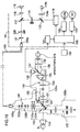
- Fig. 4 is a schematic structural view of an optical system and a control system of the apparatus in the first embodiment.
- Numeral 10 is a Nd:YAG laser serving as a treatment laser source which emits a treatment beam having a dominant wavelength of 1064nm.
- Numeral 11 is a half-wavelength plate for rotating the direction of polarization of the treatment beam.
- Numeral 12 is a polarizing filter placed at the Brewster angle. The wavelength plate 11 is rotated by operation of an energy adjusting knob not shown to adjust the power of the treatment beam to be irradiated to the affected part in combination with the polarizing filter 12.
- Numeral 13 is a beam splitter. A part of the treatment beam passed through the polarizing filter 12 is reflected by the beam splitter 13 to enter a power sensor 14 which detects the power of the treatment beam.
- Numeral 15 is a safety shutter serving to intercept the treatment beam when inserted on the beam path in a predetermined case for example of an oscillation test or occurrence of an abnormal event. While the shutter 15 is out of the beam path, the treatment beam being not intercepted by the shutter 15 is expanded by a group of expander lenses 16. The treatment beam is then reflected by a dichroic mirror 17 to made coaxial with the aiming beam (which is a red light having a dominant wavelength of 633nm) emitted from a semiconductor laser 18 serving as an aiming laser source. The aiming beam emitted from the laser source 18 is made into parallel luminous flux by a lens 19 and split into two beams by an aperture 20 having two openings formed symmetrically with respect to an optical axis L.
- aiming beam which is a red light having a dominant wavelength of 633nm
- Numeral 21 is a group of expander lenses for expanding each luminous flux of the treatment beam and the aiming beam.
- Numeral 22 is a dichroic mirror which reflects most of the treatment beam and the aiming beam, while transmitting an observation light, whereby to make the optical axis L coaxial with the optical axis of an objective lens 23.
- the treatment beam after reflected by the dichroic mirror 22, is focused on a point near the affected part of the patient's eye E through the objective lens 23 and a contact lens 24.
- the two split aiming beams are reflected by the dichroic mirror 22 and coincide with each other at a reference focus point of the treatment beam.
- the focus point of the treatment beam may be shifted with respect to the coincident point of the aiming beams by movement of the expander lenses 16 in the optical axis direction.
- Numeral 25 is a slit light projecting optical system.
- the slit light from the projecting optical system 25 is delivered to illuminate the eye E through the contact lens 24.
- Numeral 26 is a CCD camera for receiving the reflection light from the eye E. The image picked-up by the CCD camera 26 is displayed on the display 5.
- Numeral 30 is a controller for controlling the whole apparatus.
- Numeral 31 is an image processing section for processing the images of the two aiming beams picked-up by the camera 26 to detect the overlapping condition of the images.
- Fig. 5 is an explanatory view of the method of detecting the overlapping condition of the aiming beams by extracting only the images of the aiming beams and its surrounding area picked-up by the camera 26.
- numerals 50a and 50b denote the images of the two split aiming beams irradiated in two directions to the eye E. For example, they are the images of the aiming beams reflected at the desired point (the area to be treated) such as a point in posterior capsule and picked-up by the camera 26.
- the image processing is executed in the following manner.
- the image processing section 31 first extracts the images 50a and 50b of the aiming beams based on a difference in light quantity with respect to the surroundings in the image data coming from the camera 26. Sequentially, a straight line Xa is created to come in contact with the uppermost end of the extracted images of the aiming beams (which is an upper end of the image 50a of the aiming beam in the present embodiment) and to be parallel with an X-axis, and another straight line Xb is created to come in contact with the lowermost end of the images (which is an lower end of the image 50b in the present embodiment) and to be parallel with the X-axis, as shown in Fig. 5A.
- a straight line Ya is created to come in contact with the leftmost end of the images (which is a left end of either one of the images 50a and 50b) and to be parallel with a Y-axis
- another straight line Yb is created to come in contact with the rightmost end of the images (which is a right end of either one of the images 50a and 50b) and to be parallel with the Y-axis.
- the straight lines Xa, Xb, Ya, and Yb created as above define a rectangle region 51.
- This region 51 changes in area depending on an overlapping condition of the two images of the aiming beams, namely, a coincident state of those images.
- the image processing section 31 determines that sighting to the treatment area is completed, namely, that the sighting point is proper.
- an operator sets laser irradiation conditions such as the power of the treatment beam and others.
- the controller 30 then causes the display 5 to display the set laser irradiation conditions as setting information 53 in a lower part on the display 5 (see Fig. 6). With the laser irradiation conditions displayed on the display 5, the operator can confirm the laser irradiation conditions without the need of directly viewing the main unit 1 side (the control panel 3).
- the operator may place the display 5 in an easy-to-see place in consideration of treatment using the contact lens 24.
- the operator moves the main unit 1 until the image of the eye E appears on the display 5.
- the two images of the aiming beams reflected by the treatment area come to appear.
- the operator further operates the joystick 4 to slightly move the main unit 1 so that the images 50a and 50b of the aiming beams overlap each other.
- the image processing section 31 detects the overlapping condition (the coincident state) of the images 50a and 50b by the image processing at all times to transmit the image information (data) to the controller 30.
- the potentiometer 9 transmits the movement information (data) on the movement of the main unit 1 to the controller 30.
- the controller 30 causes the display 5 to display the information (data) on the coincident state of the aiming beams with respect to the treatment area based on the image information (data) coming from the image processing section 31 and the movement information (data) coming from the potentiometer 9 respectively.
- the controller 30 can find the deviation direction of the coincident point of the aiming beams (i.e., the focus point of the treatment beam) with respect to a proper sighting point based on the information (data) on the moving direction of the main unit 1 from the potentiometer 9 and the information (data) on the changes in area of the region 51 (which is the information on the overlapping condition of the images of the aiming beams).
- the controller 30 causes the display 5 to display an "ant" sign representing that effect and an arrow mark 55 indicating the direction in which the main unit 1 should be moved.
- the operator viewing the displayed information, operates the joystick 4 to move the main unit 1 forward.
- the images 50a and 50b of the aiming beams come to overlap each other on the treatment area, resulting in difficulty in recognizing them with the naked eye of the operator. However, the operator can perform the sighting based on the information displayed on the display 5.
- the controller 30 causes the display 5 to display an "OK" sign and a mark 56 indicating that the sighting is the most proper.
- the operator stops the sighting and depresses the trigger switch 4a to start irradiation of the treatment beam to the treatment area.
- the sighting can be executed based on the information (data) produced by the image processing, so that the operator can properly perform the sighting even if the coincident state of the aiming beams is difficult for the operator to recognize.
- control panel 3 is used to set the laser irradiation conditions, but it is not limited thereto.
- the display 5 may be configured in a touch panel type so as to allow the operator to set the laser irradiation condition with a touch of the screen of the display 5.
- the deviation direction of the coincident point of the aiming beams can also be found in the following manner.
- a shutter 27 is provided to alternately open the openings 20a and 20b of the aperture 20.
- the controller 30 determines the deviation direction of the coincident point of the aiming beams and the propriety as to whether the sighting is proper.
- the opening 20a is opened to allow irradiation of the aiming beam, whereby the image 50a shown in Fig. 5A is detected.
- the image 50b is detected.
- the coincident point is deviated to the rear side (in the direction F)
- the detected image is opposite to above.
- the deviation direction in relation to the coincident point can be found; the operator's side or the rear side.
- the propriety of the sighting can be determined according to whether the distance between the centers of the images 50a and 50b of the aiming beams is within a predetermined acceptable range.
- the sighting also can be executed automatically (see Figs. 5 and 8).
- the controller 30 drives a lens driving section not shown consisted of motors and cams to move the lens 23 by a predetermined amount in a predetermined direction (which may be either direction of the optical axis) (S2).
- a predetermined direction which may be either direction of the optical axis
- S2 the controller 30 drives a lens driving section not shown consisted of motors and cams to move the lens 23 by a predetermined amount in a predetermined direction (which may be either direction of the optical axis) (S2).
- S3:YES the lens 23 is further moved in the same direction as the predetermined direction (S4).
- the lens 23 is moved in the reverse direction to reduce the area of the region 51.
- the lens 23 is then stopped when the region 51 is reduced to the minimum area (S7). If NO in S6, on the other hand, the lens 23 is further moved in the same direction as in S4 (S8).
- the lens 23 can be easily returned to the position where the area of the region 51 reaches the minimum.
- the lens 23 is moved in the reverse direction to reduce the area of the region 51 (S5). Then, when the area of the region 51 comes to increase (S6:YES), the lens 23 is moved in the reverse direction to in S5 and is stopped when the region 51 is reduced to the minimum area (S7). If No in S6, the lens 23 is further moved in the same direction as in S5 (S8).
- the OK sign and the mark 56 are displayed on the display 5. Viewing the displayed information, the operator stops the sighting and depresses the trigger switch 4a to start irradiation of the treatment beam to the treatment area.
- the deviation direction of the coincident point of the aiming beams and the propriety of the sighting can be determined based on the information (data) on the images 50a and 50b of the aiming beams by the image processing and the information (data) on opening/closing of the shutter 27, thus enabling the automatic sighting.
- the apparatus may be arranged to automatically irradiate the treatment beam after completion of the sighting, where the trigger switch 4a may be omitted. It may also be arranged to preclude laser irradiation until the sighting is completed by inserting the shutter 15 in the beam path. The same goes for the manual sighting mentioned above.
- the automatic sighting is conducted by movement of the lens 23 in the optical axis direction in the above embodiment
- the sighting may be conducted by automatic movement of the main unit 1 caused by means of a mechanism for electrically moving the main unit 1 forward and backward based on the information and others by the image processing.
- the manual sighting may be executed by movement of the lens 23 by operation of a knob not shown instead of movement of the main unit 1 by operation of the joystick 4.
- the automatic sighting is effective in a conventional laser treatment apparatus provided with a microscope.
- FIG. 9 is a schematic perspective view of a laser treatment apparatus (Green-YAG laser photocoagulation apparatus) in the second embodiment.
- Numeral 101 is a main unit of the laser treatment apparatus for emitting a treatment laser beam of continuous wave (which is hereinafter simply referred to as a treatment beam).
- the main unit 101 is internally provided with a treatment laser source, an aiming laser source, a light delivery optical system, and a controller, and others.
- Numeral 102 is a stand movable up and down.
- Numeral 104 is a joystick (and a rotating knob) used for moving the main unit 101 and is provided at its top with a trigger switch 104a for generating an instruction signal of emission of the treatment beam.
- Numeral 103 is a control panel used for setting laser irradiation conditions such as the power and the number of pulses of the treatment beam, the luminous intensity of a laser beam for aiming (which is hereinafter simply referred to as an aiming beam).
- Numeral 105 is a slit-lamp delivery unit for irradiating the treatment beam to an affected part of a patient's eye E while allowing an operator to observe the affected part.
- the slit-lamp delivery unit 105 is essentially consisted of a laser irradiation section 105a internally provided with an irradiation optical system 140, an illumination section 105b internally provided with an illumination optical system 125, and a microscopic section 105c internally provided with an observation optical system 150.
- Numeral 107 is a cable for transmitting the image information (data) from a CCD camera 126 included in the observation optical system 150 to the main unit 101.
- Numeral 109 is a toot switch serving as a trigger switch used for generating an instruction signal of emission of the treatment beam.
- Fig. 10 is a schematic structural view of an optical system and a control system of the apparatus in the second embodiment.
- Numeral 110 is a laser source which is an Nd:YAG laser capable of oscillating a fundamental wavelength of 1064nm.
- the laser source 110 generates a green treatment beam of 532nm (linearly polarized light) which is double the fundamental wavelength.
- a part of the treatment beam emitted from the laser source 110 is reflected by a beam splitter 113 and, after passing through a diffusing plate 114a, is detected by a power sensor 114b.
- Numeral 115 is a first safety shutter for intercepting the treatment beam.
- Numeral 117 is a dichroic mirror for reflecting the treatment beam to make it coaxial with the aiming beam (which is a red light of a dominant wavelength of 633nm) from a semiconductor laser 118 serving as an aiming laser source.
- Numeral 119 is a collimator lens and numeral 120 is a second safety shutter which is inserted in the beam path while the aiming laser source 118 does not emit the aiming beam.
- the shutter 120 is moved out of the beam path, the treatment beam and the aiming beam are allowed to pass without interception by the shutter 120 and are converged by a focusing lens 121 into an entrance 106a of an optical fiber 106.
- Numeral 140 is an irradiation optical system in the laser irradiation section 105a.
- the treatment beam and the aiming beam delivered to the system 140 through the fiber 106 pass through a relay lens 122a, a group of zoom lenses 122b movable in the optical path for changing a spot diameter of the beams, and an objective lens 123.
- the beams are then reflected by a movable mirror 127 to irradiate the affected part of the eye E through a contact lens 124.
- the objective lens 123 is structured of a fixed lens 123a and a movable lens 123b. Moving the movable lens 123b in the optical axis direction executes a minute sighting.
- Numeral 125 is a slit-light projecting optical system in the illumination section 105b. The slit light from this system 125 illuminates the eye E through the contact lens 124.
- Numeral 150 is an observation optical system in the microscopic section 105c.
- This microscopic section 105 is designed for binocular observation and provided with a pair of the observation optical systems 150, though only one of the systems 150 is shown in Fig. 10.
- the observation optical system 150 includes an objective lens 151, a group of variable magnification lenses 152, a protective filter 153, a group of erect prisms 154, a field diaphragm 155, and eyepieces 156.
- a half mirror 157 is disposed between the erect prisms 154 and the field diaphragm 155 on either one of binocular observation optical paths. The light reflected by the half mirror 157 is received by a CCD camera 126.
- Numeral 130 is a controller for controlling the whole apparatus.
- Numeral 131 is an image processing section for processing the image of the aiming beam picked-up by the camera 126 to detect a forming state (a spot diameter) of the image.
- the lens 123b and the lens 151 are moved interlockingly on respective optical axes by means of corresponding lens driving sections 132 and 133.
- the image processing section 131 Upon depression of an automatic sighting switch not shown on the control panel 103 (S11), the image processing section 131 extracts the image of the aiming beam based on a difference in light quantity with respect to the surroundings in the image data transmitted from the camera 126 to detect the spot diameter of the aiming beam. Subsequently, the controller 130 causes the lens driving sections 132 and 133 to move the lenses 123b and 151 in a predetermined direction (which may be either direction of each of the optical axes) by a predetermined amount whereby a change of the spot diameter can be recognized (S12). The image processing section 131 detects the spot diameter which varies with the movement of the lenses 123b and 151 and transmits the information (data) on the spot diameter to the controller 130.
- a predetermined direction which may be either direction of each of the optical axes
- the controller 130 compares the spot diameters between before and after the movement of the lenses 123b and 151. If the spot diameter after the lens movement is smaller than that before the lens movement (S13:YES), the controller 130 further moves the lenses 123b and 151 in the same direction as above (S14). It the spot diameter after the lens movement is larger (S13:NO), to the contrary, the controller 130 moves the lenses 123b and 151 in the reverse direction (S15).
- the image processing section 131 detects the spot diameter of the aiming beam continuously and transmits the information (data) thereon to the controller 130.
- the controller 130 stops movements of the lenses 123b and 151 at the time when the spot diameter increases past the minimum value (S16:YES), and then moves the lenses 123b and 151 in the reverse direction to in S14 (for S13: YES) or in S15 (for S13: NO) to return them to the positions where the minimum value of the spot diameter is detected (S17). If NO in S16, on the other hand, the lenses 123b and 151 are moved in the same direction as in S14 (for S13: YES) or in S15 (for S13: NO) (S18).
- the lenses 123b and 151 can be easily returned to the positions where the minimum spot diameter is detected. Using the above manner, the automatic sighting can be conducted.
- the lenses 123b and 151 are moved interlockingly on respective optical axes, However, it is not so difficult for the operator to conduct sighting by manual operation while observing the affected part until the surroundings of the affected part is clearly observed. Accordingly, it is possible to move only the lens 123b without moving the lens 151.
- the automatic sighting is conducted by movement of the lenses 123b and 151 in the respective optical axis directions.
- An alternative design is to provide a mechanism for electrically move the main unit 101 forward and backward whereby to execute the sighting by automatically moving the main unit 101 based on the information (data) obtained by the image processing.
- the apparatus of the second embodiment may be arranged such that manual sighting is conducted by displaying the information (data) on the display, instead of the automatic sighting.
- the automatic sighting switch may be provided on the head of the joystick instead of the control panel.
- the foot switch may also be used as a trigger switch.
- it may be provided a selection switch for selecting use/nonuse of the automatic sighting.
- the operator can easily observe the patient's eye in a comfortable position.
- the apparatus can ensure accuracy and easiness in sighting to focus the treatment laser beam to the desired point.
Landscapes
- Health & Medical Sciences (AREA)
- Ophthalmology & Optometry (AREA)
- Heart & Thoracic Surgery (AREA)
- Vascular Medicine (AREA)
- Optics & Photonics (AREA)
- Surgery (AREA)
- Engineering & Computer Science (AREA)
- Biomedical Technology (AREA)
- Physics & Mathematics (AREA)
- Nuclear Medicine, Radiotherapy & Molecular Imaging (AREA)
- Life Sciences & Earth Sciences (AREA)
- Animal Behavior & Ethology (AREA)
- General Health & Medical Sciences (AREA)
- Public Health (AREA)
- Veterinary Medicine (AREA)
- Laser Surgery Devices (AREA)
Abstract
Description
- The present invention relates to a laser treatment apparatus for irradiating an affected part of a patient's eye with a treatment laser beam.
- For treatment for aftercataract and so on of a patient's eye, there conventionally has been used a laser treatment apparatus (laser operation equipment) for irradiating an affected part of the patient's eye with a treatment laser beam of pulse wave. The apparatus of this kind is designed to vaporize and crush the tissue of the affected part by focusing the treatment laser beam on a desired point (an area to be treated) of the affected part, thereby forming plasma to generate shock waves. Accordingly, the importance is to precisely focus the treatment laser beam on the desired point. For achieving this purpose, there has been known a method of focusing a treatment laser beam on a desired point after irradiating two (or more) visible aiming beams so as to coincide with each other (i.e., to overlap two images of the aiming beams) at the desired point on which the treatment laser beam is to be focused. It is to be noted that the coincidence of two aiming beams at the desired point for the focusing of the treatment laser beam on the desired point is referred hereinafter to as "sighting".
- Moreover, there is a method of shifting a focus point of the treatment laser beam to the coincident point of the aiming beams. In this case, the sighting is also important.
- For treatment for retinal diseases, there has been used a laser treatment apparatus (photocoagulation apparatus) for irradiating an affected part of a patient's eye with a treatment laser beam of continuous wave. The apparatus of this type is designed so that a visible aiming beam is irradiated to focus on a desired point which is the same as a focus point of the treatment laser beam to form an image with the minimum spot diameter, whereby the treatment laser beam is precisely focused on the desired point. It is also noted that the focusing of the aiming beam on the desired point to ensure the focusing of the treatment laser beam thereon is also referred to as "sighting".
- The sighting, however, is performed by an operator while observing the coincident state of the two aiming beams (the overlapping condition of the two images of the aiming beams) or the focusing condition of the aiming beam (the spot diameter of the image of the aiming beam) through eyepieces of a microscopic section of the apparatus. This would cause a difficulty for low-skilled operators in judging the propriety of the sighting. Furthermore, differences among operators may be included in determinations about the propriety of the sighting.
- During treatment, for example, during sighting of the aiming beams or irradiating of the treatment laser beam, the operator has to observe the patient's eye through the eyepieces of the microscopic section while holding a contact lens by one hand on the patient's eye. Thus, some operators who are for example of short stature must operate and observe in a forced or uncomfortable position.
- The present invention has been made in view of the above circumstances and has an object to overcome the above problems and to provide a laser treatment apparatus which allows an operator to easily observe a patient's eye and to precisely easily perform sighting in order to focus a treatment laser beam on a desired point.
- Additional objects and advantages of the invention will be set forth in part in the description which follows and in part will be obvious from the description, or may be learned by practice of the invention. The objects and advantages of the invention may be realized and attained by means of the instrumentalities and combinations particularly pointed out in the appended claims.
- To achieve the purpose of the invention, there is provided a laser treatment apparatus for irradiating an affected part of a patient's eye with a treatment laser beam to treat the affected part, including: treatment beam irradiation means including a first irradiation optical system for irradiating the treatment beam; aiming beam irradiation means including a second irradiation optical system for irradiating an aiming beam, the second irradiation optical system being optically adjusted such that sighting of the treatment beam is completed when the aiming beam forms a predetermined shape on a reflection plane; image pickup means including an image pickup optical system for imaging an area including the affected part of the patient's eye; sighting detection means for processing an image of the aiming beam picked-up by the image pickup means to detect a sighting state; movement detection means for detecting movement in an optical axis direction of at least one of at least a part of the image pickup optical system and at least a part of the irradiation optical system; and determination means for determining a direction in which at least one of at least the part of the image pickup optical system and at least the part of the irradiation optical system is to be moved based on results detected by the sighting detection means and the movement detection means respectively.
- It is preferable that the laser treatment apparatus further includes observation means including a display for displaying an image picked up by the image pickup means on the display.
- It is preferable that the laser treatment apparatus further includes display control means for causing the display to display that the sighting state is proper based on the result detected by the sighting detection means.
- It is further preferable that the laser treatment apparatus further includes display control means for causing the display to display the direction in which at least one of at least the parts of the image pickup optical system and the irradiation optical system are to be moved based on the result detected by the determination means.
- Preferably, in the laser treatment apparatus the display is place-changeably mounted on the apparatus.
- It is preferable that the laser treatment apparatus further includes movement means for automatically moving at least one of at least the part of the image pickup optical system and at least the part of the irradiation optical system based on the result detected by the determination means.
- It is preferable that the laser treatment apparatus further includes: movement means for automatically moving at least one of at least the part of the image pickup optical system and at least the part of the irradiation optical system; and movement control means for controlling the movement means to move at least one of at least the part of the image pickup optical system and at least the part of the irradiation optical system by a predetermined amount in a predetermined direction based on an instruction to start automatic sighting.
- Preferably, in the laser treatment apparatus the aiming beam irradiation means irradiates a plurality of aiming beams which are symmetrical about an optical axis to coincide with each other at a focus point of the treatment laser beam, and the sighting detection means detects the sighting state based on an overlapping condition of the images of the plurality of aiming beams.
- Preferably, in the laser treatment apparatus the aiming beam irradiation means irradiates the aiming beam to focus on a focus point of the treatment laser beam, and the sighting detection means detects the sighting state based on a spot diameter of the image of the aiming beam.
- Preferably, in the laser treatment apparatus the treatment beam irradiation means includes a laser source which emits a YAG laser beam as the treatment laser beam.
- The accompanying drawings, which are incorporated in and constitute a part of this specification illustrate an embodiment of the invention and, together with the description, serve to explain the objects, advantages and principles of the invention.
- In the drawings,
- Figs. 1A and 1B are schematic perspective views of a laser treatment apparatus in a first embodiment according to the present invention;
- Fig. 2 is a schematic sectional view of a mechanism for mounting a display on a main unit in the first embodiment;
- Fig. 3 is a schematic structural view of a mechanism for detecting moving directions of the main unit;
- Fig. 4 is a schematic structural view of an optical system and a control system of the apparatus in the first embodiment;
- Figs. 5A, 5B, and 5C are explanatory views of showing a method of detecting a coincident state of aiming beams by image processing;
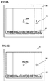
- Figs. 6A and 6B are examples of a screen appearing on the display;
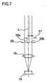
- Fig. 7 is an explanatory view of showing a method of finding a deviation direction of the aiming beams;
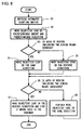
- Fig. 8 is a flowchart of showing a routine of automatic sighting in the first embodiment;
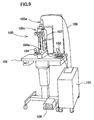
- Fig. 9 is a schematic perspective view of a laser treatment apparatus in a second embodiment according to the present invention;
- Fig. 10 is a schematic structural view of an optical system and a control system of the apparatus in the second embodiment; and
- Fig. 11 is a flowchart of showing a routine of automatic sighting in the second embodiment.
-
- A detailed description of preferred embodiments of a laser treatment apparatus embodying the present invention will now be given referring to the accompanying drawings.
- Fig. 1 is a schematic perspective view of the laser treatment apparatus (YAG laser operation apparatus) in the first embodiment according to the present invention.
-
Numeral 1 is a main unit of the apparatus for emitting a treatment laser beam (which is hereinafter simply referred to as a treatment beam) of pulsed wave. Thismain unit 1 is internally provided with a treatment laser source, an aiming laser source, a light delivery optical system, a controller, and others. Numeral 2 is a stand with a table which is movable up and down, on which themain unit 1 is mounted.Numeral 4 is a joystick used for moving themain unit 1 on the table of thestand 2 in a back-to-front and right-to-left directions. Thejoystick 4 is provided at its upper portion with a rotating knob which is used for moving themain unit 1 up and down. The moving mechanism of themain unit 1 by means of the joystick and the rotating knob are well known, of which explanation is therefore omitted. Thejoystick 4 is also provided at its top portion with atrigger switch 4a for generating an instruction signal to start emission of the treatment beam.Numeral 3 is a control panel used for setting laser irradiation conditions such as the number of pulses of the treatment beam, the power of the same, and the luminous intensity of an aiming laser beam (which is hereinafter simply referred to as an aiming beam), and others. -
Numeral 5 is a display for displaying information (data) transmitted from aCCD camera 26 and a controller 30 (which will be mentioned later) through acable 7. Thisdisplay 5 is attached on arack 6 fixedly provided to themain unit 1 as shown in Fig. 1A, and is removable from therack 6 as shown in Fig. 1B. Thedisplay 5 can thus be used in any place where an operator wishes. - The
display 5 is attached on therack 6 under the condition that asupport shaft 6a of therack 6 is inserted in ahole 5a of thedisplay 5 as shown in Fig. 2. Thedisplay 5 is rotatable about thesupport shaft 6a. -
Numeral 8 is an axle for moving themain unit 1 in a forward (an arrow F in Figs. 1A and 3) direction and a backward (an arrow B) direction. As shown in Fig. 3, in the main unit 1 a potentiometer 9 is attached on theaxle 8 through gears, whereby to allow detection of a moving direction (and also a moving amount) of themain unit 1 on the basis of a rotating direction of the axle 8 (and also a rotating amount). Information (data) on a detected moving direction (and also a moving amount) is used in a sighting operation for focusing of the treatment beam. - Fig. 4 is a schematic structural view of an optical system and a control system of the apparatus in the first embodiment.
Numeral 10 is a Nd:YAG laser serving as a treatment laser source which emits a treatment beam having a dominant wavelength of 1064nm.Numeral 11 is a half-wavelength plate for rotating the direction of polarization of the treatment beam.Numeral 12 is a polarizing filter placed at the Brewster angle. Thewavelength plate 11 is rotated by operation of an energy adjusting knob not shown to adjust the power of the treatment beam to be irradiated to the affected part in combination with thepolarizing filter 12.Numeral 13 is a beam splitter. A part of the treatment beam passed through thepolarizing filter 12 is reflected by thebeam splitter 13 to enter apower sensor 14 which detects the power of the treatment beam. -
Numeral 15 is a safety shutter serving to intercept the treatment beam when inserted on the beam path in a predetermined case for example of an oscillation test or occurrence of an abnormal event. While theshutter 15 is out of the beam path, the treatment beam being not intercepted by theshutter 15 is expanded by a group ofexpander lenses 16. The treatment beam is then reflected by adichroic mirror 17 to made coaxial with the aiming beam (which is a red light having a dominant wavelength of 633nm) emitted from asemiconductor laser 18 serving as an aiming laser source. The aiming beam emitted from thelaser source 18 is made into parallel luminous flux by alens 19 and split into two beams by anaperture 20 having two openings formed symmetrically with respect to an optical axis L. -
Numeral 21 is a group of expander lenses for expanding each luminous flux of the treatment beam and the aiming beam.Numeral 22 is a dichroic mirror which reflects most of the treatment beam and the aiming beam, while transmitting an observation light, whereby to make the optical axis L coaxial with the optical axis of anobjective lens 23. The treatment beam, after reflected by thedichroic mirror 22, is focused on a point near the affected part of the patient's eye E through theobjective lens 23 and acontact lens 24. The two split aiming beams are reflected by thedichroic mirror 22 and coincide with each other at a reference focus point of the treatment beam. The focus point of the treatment beam may be shifted with respect to the coincident point of the aiming beams by movement of theexpander lenses 16 in the optical axis direction. -
Numeral 25 is a slit light projecting optical system. The slit light from the projectingoptical system 25 is delivered to illuminate the eye E through thecontact lens 24. -
Numeral 26 is a CCD camera for receiving the reflection light from the eye E. The image picked-up by theCCD camera 26 is displayed on thedisplay 5. -
Numeral 30 is a controller for controlling the whole apparatus.Numeral 31 is an image processing section for processing the images of the two aiming beams picked-up by thecamera 26 to detect the overlapping condition of the images. - Next, explanation is made on a method of detecting the overlapping condition (coincident state) of the images of the aiming beams by image processing, referring to Fig. 5. Fig. 5 is an explanatory view of the method of detecting the overlapping condition of the aiming beams by extracting only the images of the aiming beams and its surrounding area picked-up by the
camera 26. - In Fig. 5,
numerals camera 26. - The image processing is executed in the following manner. The
image processing section 31 first extracts theimages camera 26. Sequentially, a straight line Xa is created to come in contact with the uppermost end of the extracted images of the aiming beams (which is an upper end of theimage 50a of the aiming beam in the present embodiment) and to be parallel with an X-axis, and another straight line Xb is created to come in contact with the lowermost end of the images (which is an lower end of theimage 50b in the present embodiment) and to be parallel with the X-axis, as shown in Fig. 5A. Similarly, a straight line Ya is created to come in contact with the leftmost end of the images (which is a left end of either one of theimages images - The straight lines Xa, Xb, Ya, and Yb created as above define a
rectangle region 51. Thisregion 51 changes in area depending on an overlapping condition of the two images of the aiming beams, namely, a coincident state of those images. To be more specific, when theimages region 51 is reduced. When theregion 51 is reduced to the minimum area where theimages image processing section 31 determines that sighting to the treatment area is completed, namely, that the sighting point is proper. - Operation of the laser treatment apparatus having the above configuration will be explained below.
- At first, using the
control panel 3, an operator sets laser irradiation conditions such as the power of the treatment beam and others. Thecontroller 30 then causes thedisplay 5 to display the set laser irradiation conditions as settinginformation 53 in a lower part on the display 5 (see Fig. 6). With the laser irradiation conditions displayed on thedisplay 5, the operator can confirm the laser irradiation conditions without the need of directly viewing themain unit 1 side (the control panel 3). - The operator may place the
display 5 in an easy-to-see place in consideration of treatment using thecontact lens 24. By the operation of thejoystick 4, the operator moves themain unit 1 until the image of the eye E appears on thedisplay 5. - As shown in Fig. 6A, on the
display 5 the two images of the aiming beams reflected by the treatment area come to appear. The operator further operates thejoystick 4 to slightly move themain unit 1 so that theimages image processing section 31 detects the overlapping condition (the coincident state) of theimages controller 30. - Simultaneously the potentiometer 9 transmits the movement information (data) on the movement of the
main unit 1 to thecontroller 30. Thecontroller 30 causes thedisplay 5 to display the information (data) on the coincident state of the aiming beams with respect to the treatment area based on the image information (data) coming from theimage processing section 31 and the movement information (data) coming from the potentiometer 9 respectively. - For example, when the coincident point of the aiming beams is at an operator's side (in the direction B), the
main unit 1 should be moved forward (in the direction F), whereby theregion 51 shown in Fig. 5A is reduced in area. Thecontroller 30 can find the deviation direction of the coincident point of the aiming beams (i.e., the focus point of the treatment beam) with respect to a proper sighting point based on the information (data) on the moving direction of themain unit 1 from the potentiometer 9 and the information (data) on the changes in area of the region 51 (which is the information on the overlapping condition of the images of the aiming beams). When the deviation direction of the coincident point is at the operator's side with respect to the proper sighting point, thecontroller 30 causes thedisplay 5 to display an "ant" sign representing that effect and anarrow mark 55 indicating the direction in which themain unit 1 should be moved. The operator, viewing the displayed information, operates thejoystick 4 to move themain unit 1 forward. In further sighting, theimages display 5. - When the
image processing section 31 detects that theimages controller 30 causes thedisplay 5 to display an "OK" sign and amark 56 indicating that the sighting is the most proper. When that sign appears on thedisplay 5, the operator stops the sighting and depresses thetrigger switch 4a to start irradiation of the treatment beam to the treatment area. - In the above manner, the sighting can be executed based on the information (data) produced by the image processing, so that the operator can properly perform the sighting even if the coincident state of the aiming beams is difficult for the operator to recognize.
- In the present embodiment, the
control panel 3 is used to set the laser irradiation conditions, but it is not limited thereto. Thedisplay 5 may be configured in a touch panel type so as to allow the operator to set the laser irradiation condition with a touch of the screen of thedisplay 5. - The deviation direction of the coincident point of the aiming beams (the focus point of the treatment beam) can also be found in the following manner. As shown in Fig. 7, a
shutter 27 is provided to alternately open theopenings aperture 20. Under control of thecontroller 30, theshutter 27 is driven to alternately allow irradiation of the two aiming beams. Based on the information (data) on theimages shutter 27, thecontroller 30 determines the deviation direction of the coincident point of the aiming beams and the propriety as to whether the sighting is proper. To be more specific, when the coincident point is deviated to the operator's side (in the direction B), theopening 20a is opened to allow irradiation of the aiming beam, whereby theimage 50a shown in Fig. 5A is detected. When theopening 20b is opened, theimage 50b is detected. On the other hand, when the coincident point is deviated to the rear side (in the direction F), the detected image is opposite to above. Thus, the deviation direction in relation to the coincident point can be found; the operator's side or the rear side. Alternatively, the propriety of the sighting can be determined according to whether the distance between the centers of theimages - Utilizing the above information, the sighting also can be executed automatically (see Figs. 5 and 8). Upon depression of an automatic sighting switch not shown of the control panel 3 (S1), the
controller 30 drives a lens driving section not shown consisted of motors and cams to move thelens 23 by a predetermined amount in a predetermined direction (which may be either direction of the optical axis) (S2). If theregion 51 is reduced in area in association of the movement of thelens 23 in the predetermined direction (S3:YES), thelens 23 is further moved in the same direction as the predetermined direction (S4). When the area of theregion 51 comes to increase past the minimum (S6:YES), thelens 23 is moved in the reverse direction to reduce the area of theregion 51. Thelens 23 is then stopped when theregion 51 is reduced to the minimum area (S7). If NO in S6, on the other hand, thelens 23 is further moved in the same direction as in S4 (S8). - If the moving direction and the moving amount of the
lens 23 are stored in thecontroller 30 in relation to the information (data) detected by the image processing, thelens 23 can be easily returned to the position where the area of theregion 51 reaches the minimum. - On the other hand, if the
region 51 is increased in area when thelens 23 is moved in the predetermined direction (S3:NO), thelens 23 is moved in the reverse direction to reduce the area of the region 51 (S5). Then, when the area of theregion 51 comes to increase (S6:YES), thelens 23 is moved in the reverse direction to in S5 and is stopped when theregion 51 is reduced to the minimum area (S7). If No in S6, thelens 23 is further moved in the same direction as in S5 (S8). - Upon stop of the lens 23 (completion of the sighting), the OK sign and the
mark 56 are displayed on thedisplay 5. Viewing the displayed information, the operator stops the sighting and depresses thetrigger switch 4a to start irradiation of the treatment beam to the treatment area. - In the case where the two aiming beams are alternately irradiated as shown in Fig. 7, similarly, the deviation direction of the coincident point of the aiming beams and the propriety of the sighting can be determined based on the information (data) on the
images shutter 27, thus enabling the automatic sighting. - In the automatic sighting, the apparatus may be arranged to automatically irradiate the treatment beam after completion of the sighting, where the
trigger switch 4a may be omitted. It may also be arranged to preclude laser irradiation until the sighting is completed by inserting theshutter 15 in the beam path. The same goes for the manual sighting mentioned above. - Although the automatic sighting is conducted by movement of the
lens 23 in the optical axis direction in the above embodiment, the sighting may be conducted by automatic movement of themain unit 1 caused by means of a mechanism for electrically moving themain unit 1 forward and backward based on the information and others by the image processing. - To the contrary, the manual sighting may be executed by movement of the
lens 23 by operation of a knob not shown instead of movement of themain unit 1 by operation of thejoystick 4. - It is needless to say that the automatic sighting is effective in a conventional laser treatment apparatus provided with a microscope.
- Next, a second embodiment according to the present invention will be described. Fig. 9 is a schematic perspective view of a laser treatment apparatus (Green-YAG laser photocoagulation apparatus) in the second embodiment.
-
Numeral 101 is a main unit of the laser treatment apparatus for emitting a treatment laser beam of continuous wave (which is hereinafter simply referred to as a treatment beam). Themain unit 101 is internally provided with a treatment laser source, an aiming laser source, a light delivery optical system, and a controller, and others.Numeral 102 is a stand movable up and down.Numeral 104 is a joystick (and a rotating knob) used for moving themain unit 101 and is provided at its top with atrigger switch 104a for generating an instruction signal of emission of the treatment beam.Numeral 103 is a control panel used for setting laser irradiation conditions such as the power and the number of pulses of the treatment beam, the luminous intensity of a laser beam for aiming (which is hereinafter simply referred to as an aiming beam). -
Numeral 105 is a slit-lamp delivery unit for irradiating the treatment beam to an affected part of a patient's eye E while allowing an operator to observe the affected part. The slit-lamp delivery unit 105 is essentially consisted of alaser irradiation section 105a internally provided with an irradiationoptical system 140, anillumination section 105b internally provided with an illuminationoptical system 125, and amicroscopic section 105c internally provided with an observationoptical system 150.Numeral 107 is a cable for transmitting the image information (data) from aCCD camera 126 included in the observationoptical system 150 to themain unit 101. -
Numeral 109 is a toot switch serving as a trigger switch used for generating an instruction signal of emission of the treatment beam. - Fig. 10 is a schematic structural view of an optical system and a control system of the apparatus in the second embodiment.
Numeral 110 is a laser source which is an Nd:YAG laser capable of oscillating a fundamental wavelength of 1064nm. In the present embodiment, thelaser source 110 generates a green treatment beam of 532nm (linearly polarized light) which is double the fundamental wavelength. A part of the treatment beam emitted from thelaser source 110 is reflected by abeam splitter 113 and, after passing through a diffusingplate 114a, is detected by apower sensor 114b. -
Numeral 115 is a first safety shutter for intercepting the treatment beam.Numeral 117 is a dichroic mirror for reflecting the treatment beam to make it coaxial with the aiming beam (which is a red light of a dominant wavelength of 633nm) from asemiconductor laser 118 serving as an aiming laser source.Numeral 119 is a collimator lens and numeral 120 is a second safety shutter which is inserted in the beam path while the aiminglaser source 118 does not emit the aiming beam. When theshutter 120 is moved out of the beam path, the treatment beam and the aiming beam are allowed to pass without interception by theshutter 120 and are converged by a focusinglens 121 into anentrance 106a of anoptical fiber 106. -
Numeral 140 is an irradiation optical system in thelaser irradiation section 105a. The treatment beam and the aiming beam delivered to thesystem 140 through thefiber 106 pass through arelay lens 122a, a group ofzoom lenses 122b movable in the optical path for changing a spot diameter of the beams, and anobjective lens 123. The beams are then reflected by amovable mirror 127 to irradiate the affected part of the eye E through acontact lens 124. Theobjective lens 123 is structured of a fixedlens 123a and amovable lens 123b. Moving themovable lens 123b in the optical axis direction executes a minute sighting. -
Numeral 125 is a slit-light projecting optical system in theillumination section 105b. The slit light from thissystem 125 illuminates the eye E through thecontact lens 124. -
Numeral 150 is an observation optical system in themicroscopic section 105c. Thismicroscopic section 105 is designed for binocular observation and provided with a pair of the observationoptical systems 150, though only one of thesystems 150 is shown in Fig. 10. The observationoptical system 150 includes anobjective lens 151, a group ofvariable magnification lenses 152, aprotective filter 153, a group oferect prisms 154, afield diaphragm 155, andeyepieces 156. Ahalf mirror 157 is disposed between theerect prisms 154 and thefield diaphragm 155 on either one of binocular observation optical paths. The light reflected by thehalf mirror 157 is received by aCCD camera 126. -
Numeral 130 is a controller for controlling the whole apparatus.Numeral 131 is an image processing section for processing the image of the aiming beam picked-up by thecamera 126 to detect a forming state (a spot diameter) of the image. - It is to be noted that the
lens 123b and thelens 151 are moved interlockingly on respective optical axes by means of correspondinglens driving sections - Next, explanation is made on a method for executing automatic sighting based on image processing, referring to a flowchart in Fig. 11. To focus the aiming beam on the same point as the treatment beam, the sighting is conducted such that the spot diameter of the aiming beam reflected at a desired point (the treatment area) is reduced to the minimum.
- Upon depression of an automatic sighting switch not shown on the control panel 103 (S11), the
image processing section 131 extracts the image of the aiming beam based on a difference in light quantity with respect to the surroundings in the image data transmitted from thecamera 126 to detect the spot diameter of the aiming beam. Subsequently, thecontroller 130 causes thelens driving sections lenses image processing section 131 detects the spot diameter which varies with the movement of thelenses controller 130. Thecontroller 130 then compares the spot diameters between before and after the movement of thelenses controller 130 further moves thelenses controller 130 moves thelenses - The
image processing section 131 detects the spot diameter of the aiming beam continuously and transmits the information (data) thereon to thecontroller 130. Thecontroller 130 stops movements of thelenses lenses lenses - If the moving direction and the moving amount of the
lenses lenses - In the above embodiment, the
lenses lens 123b without moving thelens 151. - In the above embodiment, the automatic sighting is conducted by movement of the
lenses main unit 101 forward and backward whereby to execute the sighting by automatically moving themain unit 101 based on the information (data) obtained by the image processing. - In the apparatus of the second embodiment, as well as in the first embodiment, it may be arranged such that manual sighting is conducted by displaying the information (data) on the display, instead of the automatic sighting.
- The automatic sighting switch may be provided on the head of the joystick instead of the control panel. In this case, the foot switch may also be used as a trigger switch. Moreover, it may be provided a selection switch for selecting use/nonuse of the automatic sighting.
- With the laser treatment apparatus in the above embodiments, the operator can easily observe the patient's eye in a comfortable position. The apparatus can ensure accuracy and easiness in sighting to focus the treatment laser beam to the desired point.
- The foregoing description of the preferred embodiment of the invention has been presented for purposes of illustration and description. It is not intended to be exhaustive or to limit the invention to the precise form disclosed, and modifications and variations are possible in light of the above teachings or may be acquired from practice of the invention. The embodiment chosen and described in order to explain the principles of the invention and its practical application to enable one skilled in the art to utilize the invention in various embodiments and with various modifications as are suited to the particular use contemplated. It is intended that the scope of the invention be defined by the claims appended hereto, and their equivalents.
Claims (10)
- A laser treatment apparatus for irradiating an affected part of a patient's eye with a treatment laser beam to treat the affected part, including:treatment beam irradiation means including a first irradiation optical system (10-13, 16, 17, 21-23; 110, 113, 117, 121, 106, 140) for irradiating the treatment beam;aiming beam irradiation means including a second irradiation optical system (17-23; 118, 119, 117, 121, 106, 140) for irradiating an aiming beam, the second irradiation optical system being optically adjusted such that sighting of the treatment beam is completed when the aiming beam forms a predetermined shape on a reflection plane;image pickup means including an image pickup optical system (22, 23, 26; 127, 151-154, 126, 157) for imaging an area including the affected part of the patient's eye;sighting detection means (31; 131)for processing an image of the aiming beam picked-up by the image pickup means to detect a sighting state;movement detection means (9, 30; 130) for detecting movement in an optical axis direction of at least one of at least a part of the image pickup optical system and at least a part of the irradiation optical system; anddetermination means (30; 130) for determining a direction in which at least one of at least the part of the image pickup optical system and at least the part of the irradiation optical system is to be moved based on results detected by the sighting detection means and the movement detection means respectively.
- The laser treatment apparatus according to claim 1 further including observation means including a display (5) for displaying an image picked up by the image pickup means on the display.
- The laser treatment apparatus according to claim 2 further including display control means (30) for causing the display to display that the sighting state is proper based on the result detected by the sighting detection means.
- The laser treatment apparatus according to claim 2 further including display control means (30) for causing the display to display the direction in which at least one of at least the parts of the image pickup optical system and the irradiation optical system are to be moved based on the result detected by the determination means.
- The laser treatment apparatus according to claim 2, wherein the display is place-changeably mounted on the apparatus.
- The laser treatment apparatus according to one of claims 1 to 5, further including movement means (30; 130, 132, 133) for automatically moving at least one of at least the part of the image pickup optical system and at least the part of the irradiation optical system based on the result detected by the determination means.
- The laser treatment apparatus according to one of claims 1 to 5, further including:movement means (30; 130, 132, 133) for automatically moving at least one of at least the part of the image pickup optical system and at least the part of the irradiation optical system; andmovement control means (30; 130) for controlling the movement means to move at least one of at least the part of the image pickup optical system and at least the part of the irradiation optical system by a predetermined amount in a predetermined direction based on an instruction to start automatic sighting.
- The laser treatment apparatus according to one of claims 1 to 7,
wherein the aiming beam irradiation means irradiates a plurality of aiming beams which are symmetrical about an optical axis to coincide with each other at a focus point of the treatment laser beam, and the sighting detection means detects the sighting state based on an overlapping condition of the images of the plurality of aiming beams. - The laser treatment apparatus according to one of claims 1 to 7,
wherein the aiming beam irradiation means irradiates the aiming beam to focus on a focus point of the treatment laser beam, and the sighting detection means detects the sighting state based on a spot diameter of the image of the aiming beam. - The laser treatment apparatus according to one of claims 1 to 9,
wherein the treatment beam irradiation means includes a laser source (10, 110) which emits a YAG laser beam as the treatment laser beam.
Applications Claiming Priority (4)
| Application Number | Priority Date | Filing Date | Title |
|---|---|---|---|
| JP24719299A JP2001070337A (en) | 1999-09-01 | 1999-09-01 | Laser surgery equipment |
| JP24719299 | 1999-09-01 | ||
| JP27648199A JP2001095816A (en) | 1999-09-29 | 1999-09-29 | Laser therapy equipment |
| JP27648199 | 1999-09-29 |
Publications (2)
| Publication Number | Publication Date |
|---|---|
| EP1080706A1 true EP1080706A1 (en) | 2001-03-07 |
| EP1080706B1 EP1080706B1 (en) | 2005-01-19 |
Family
ID=26538123
Family Applications (1)
| Application Number | Title | Priority Date | Filing Date |
|---|---|---|---|
| EP00118775A Expired - Lifetime EP1080706B1 (en) | 1999-09-01 | 2000-08-30 | Laser treatment apparatus |
Country Status (3)
| Country | Link |
|---|---|
| US (1) | US6932807B1 (en) |
| EP (1) | EP1080706B1 (en) |
| DE (1) | DE60017514T2 (en) |
Cited By (16)
| Publication number | Priority date | Publication date | Assignee | Title |
|---|---|---|---|---|
| EP1228740A1 (en) * | 2001-02-01 | 2002-08-07 | Nidek Co., Ltd. | Laser eye treatment apparatus |
| WO2009124140A1 (en) * | 2008-04-01 | 2009-10-08 | Amo Development, Llc | Ophthalmic laser apparatus, system, and method with high resolution imaging |
| ITRM20090071A1 (en) * | 2009-02-17 | 2010-08-18 | Strumenti Oftalmici C S O S R L Costruzioni | SLOT LAMP WITH LASER OUTPUT |
| US9421131B2 (en) | 2008-04-01 | 2016-08-23 | Amo Development, Llc | System and method of iris-pupil contrast enhancement |
| US20210235986A1 (en) * | 2020-02-04 | 2021-08-05 | Vialase, Inc. | System and method for locating a surface of ocular tissue for glaucoma surgery based on dual aiming beams |
| US11173067B2 (en) | 2018-09-07 | 2021-11-16 | Vialase, Inc. | Surgical system and procedure for precise intraocular pressure reduction |
| US11246754B2 (en) | 2018-07-16 | 2022-02-15 | Vialase, Inc. | Surgical system and procedure for treatment of the trabecular meshwork and Schlemm's canal using a femtosecond laser |
| US11583445B2 (en) | 2018-09-07 | 2023-02-21 | Vialase, Inc. | Non-invasive and minimally invasive laser surgery for the reduction of intraocular pressure in the eye |
| US11612315B2 (en) | 2020-04-09 | 2023-03-28 | Vialase, Inc. | Alignment and diagnostic device and methods for imaging and surgery at the irido-corneal angle of the eye |
| US11666483B2 (en) | 2018-07-16 | 2023-06-06 | Vialase, Inc. | System and method for angled optical access to the irido-corneal angle of the eye |
| US11986424B2 (en) | 2018-07-16 | 2024-05-21 | Vialase, Inc. | Method, system, and apparatus for imaging and surgical scanning of the irido-corneal angle for laser surgery of glaucoma |
| US12002567B2 (en) | 2021-11-29 | 2024-06-04 | Vialase, Inc. | System and method for laser treatment of ocular tissue based on patient biometric data and apparatus and method for determining laser energy based on an anatomical model |
| US12016799B2 (en) | 2018-07-16 | 2024-06-25 | Vialase, Inc. | Integrated surgical system and method for treatment in the irido-corneal angle of the eye |
| US12226345B2 (en) | 2019-12-14 | 2025-02-18 | Vialase, Inc. | Near eye reflective devices for diagnostic and therapeutic ophthalmic procedures |
| US12245974B2 (en) | 2018-07-16 | 2025-03-11 | Vialase, Inc. | System and method for clearing an obstruction from the path of a surgical laser |
| US12642699B2 (en) | 2022-08-17 | 2026-06-02 | Vialase, Inc. | System and method for laser treatment of ocular tissue using non-collinear imaging |
Families Citing this family (27)
| Publication number | Priority date | Publication date | Assignee | Title |
|---|---|---|---|---|
| AU2002951467A0 (en) | 2002-09-18 | 2002-10-03 | Ellex Medical Pty Ltd | Ophthalmic laser |
| US7766903B2 (en) * | 2003-12-24 | 2010-08-03 | The Board Of Trustees Of The Leland Stanford Junior University | Patterned laser treatment of the retina |
| DE102004014181A1 (en) | 2004-03-23 | 2005-10-06 | Carl Zeiss Meditec Ag | Material processing device and method |
| US7584756B2 (en) * | 2004-08-17 | 2009-09-08 | Amo Development, Llc | Apparatus and method for correction of aberrations in laser system optics |
| JP4492874B2 (en) * | 2005-03-31 | 2010-06-30 | 株式会社ニデック | Ophthalmic laser treatment device |
| US8232535B2 (en) * | 2005-05-10 | 2012-07-31 | Tomotherapy Incorporated | System and method of treating a patient with radiation therapy |
| WO2009033111A2 (en) | 2007-09-06 | 2009-03-12 | Lensx Lasers, Inc. | Precise targeting of surgical photodisruption |
| US8467497B2 (en) * | 2007-10-25 | 2013-06-18 | Tomotherapy Incorporated | System and method for motion adaptive optimization for radiation therapy delivery |
| JP2011502010A (en) * | 2007-10-25 | 2011-01-20 | トモセラピー・インコーポレーテッド | System and method for motion adaptive optimization of radiation therapy delivery |
| US8130904B2 (en) | 2009-01-29 | 2012-03-06 | The Invention Science Fund I, Llc | Diagnostic delivery service |
| US8041008B2 (en) | 2009-01-29 | 2011-10-18 | The Invention Science Fund I, Llc | Diagnostic delivery service |
| US9492322B2 (en) | 2009-11-16 | 2016-11-15 | Alcon Lensx, Inc. | Imaging surgical target tissue by nonlinear scanning |
| US8265364B2 (en) | 2010-02-05 | 2012-09-11 | Alcon Lensx, Inc. | Gradient search integrated with local imaging in laser surgical systems |
| US8414564B2 (en) | 2010-02-18 | 2013-04-09 | Alcon Lensx, Inc. | Optical coherence tomographic system for ophthalmic surgery |
| US8398236B2 (en) | 2010-06-14 | 2013-03-19 | Alcon Lensx, Inc. | Image-guided docking for ophthalmic surgical systems |
| US9532708B2 (en) | 2010-09-17 | 2017-01-03 | Alcon Lensx, Inc. | Electronically controlled fixation light for ophthalmic imaging systems |
| US20120089134A1 (en) * | 2010-10-11 | 2012-04-12 | Christopher Horvath | Contactless Photodisruptive Laser assisted Cataract Surgery |
| US8512319B2 (en) * | 2010-12-28 | 2013-08-20 | Nidek Co., Ltd. | Ophthalmic laser treatment apparatus |
| JP5958027B2 (en) * | 2011-03-31 | 2016-07-27 | 株式会社ニデック | Ophthalmic laser treatment device |
| US8459794B2 (en) | 2011-05-02 | 2013-06-11 | Alcon Lensx, Inc. | Image-processor-controlled misalignment-reduction for ophthalmic systems |
| US9622913B2 (en) | 2011-05-18 | 2017-04-18 | Alcon Lensx, Inc. | Imaging-controlled laser surgical system |
| US8398238B1 (en) | 2011-08-26 | 2013-03-19 | Alcon Lensx, Inc. | Imaging-based guidance system for ophthalmic docking using a location-orientation analysis |
| US9023016B2 (en) | 2011-12-19 | 2015-05-05 | Alcon Lensx, Inc. | Image processor for intra-surgical optical coherence tomographic imaging of laser cataract procedures |
| US9066784B2 (en) | 2011-12-19 | 2015-06-30 | Alcon Lensx, Inc. | Intra-surgical optical coherence tomographic imaging of cataract procedures |
| US9211214B2 (en) * | 2012-03-21 | 2015-12-15 | Valeant Pharmaceuticals International, Inc | Photodynamic therapy laser |
| CN105027227B (en) | 2013-02-26 | 2017-09-08 | 安科锐公司 | Electromagnetically actuated multi-leaf collimator |
| US10420608B2 (en) * | 2014-05-20 | 2019-09-24 | Verily Life Sciences Llc | System for laser ablation surgery |
Citations (5)
| Publication number | Priority date | Publication date | Assignee | Title |
|---|---|---|---|---|
| EP0293126A1 (en) * | 1987-05-20 | 1988-11-30 | Keeler Limited | Photocoagulation apparatus |
| US5076685A (en) * | 1989-07-04 | 1991-12-31 | Carl-Zeiss-Stiftung | Apparatus for ophthalmological laser-therapy instruments |
| US5285223A (en) * | 1991-08-30 | 1994-02-08 | Nikon Corporation | Ophthalmic optical apparatus having an alignment optical system |
| US5488443A (en) * | 1992-11-07 | 1996-01-30 | Nidek Co., Ltd. | Portable laser apparatus for ophthalmological operation |
| US5537163A (en) * | 1994-06-17 | 1996-07-16 | Nikon Corporation | Ophthalmologic apparatus with automatic focusing using two reference marks and having an in-focus detecting system |
Family Cites Families (16)
| Publication number | Priority date | Publication date | Assignee | Title |
|---|---|---|---|---|
| US4638801A (en) * | 1983-07-06 | 1987-01-27 | Lasers For Medicine | Laser ophthalmic surgical system |
| DE3607721A1 (en) | 1986-03-08 | 1987-09-10 | Rodenstock Instr | DEVICE FOR LASER TREATMENT OF THE EYE |
| US5177511A (en) | 1986-11-08 | 1993-01-05 | G. Rodenstock Instruments Gmbh | Apparatus for producing images of an object and in particular for observing the rear portions of the eye |
| US4907586A (en) * | 1988-03-31 | 1990-03-13 | Intelligent Surgical Lasers | Method for reshaping the eye |
| US5364390A (en) * | 1988-05-19 | 1994-11-15 | Refractive Laser Research And Development, Inc. | Handpiece and related apparatus for laser surgery and dentistry |
| US5098426A (en) * | 1989-02-06 | 1992-03-24 | Phoenix Laser Systems, Inc. | Method and apparatus for precision laser surgery |
| US5048946A (en) * | 1990-05-15 | 1991-09-17 | Phoenix Laser Systems, Inc. | Spectral division of reflected light in complex optical diagnostic and therapeutic systems |
| US5439462A (en) * | 1992-02-25 | 1995-08-08 | Intelligent Surgical Lasers | Apparatus for removing cataractous material |
| JPH0690907A (en) | 1992-09-11 | 1994-04-05 | Kowa Co | Fundus camera |
| JP3512822B2 (en) | 1992-11-19 | 2004-03-31 | 興和株式会社 | Photocoagulation equipment |
| JPH0767909A (en) | 1993-06-28 | 1995-03-14 | Kowa Co | Photo-coagulator |
| IL108335A (en) * | 1994-01-14 | 1999-04-11 | Laser Ind Ltd | Laser microscope adaptor apparatus with auto-focus |
| US5980513A (en) * | 1994-04-25 | 1999-11-09 | Autonomous Technologies Corp. | Laser beam delivery and eye tracking system |
| GB2293659B (en) | 1994-09-30 | 1998-06-24 | Nidek Kk | Ophthalmic apparatus provided with alignment mechanism |
| JPH08299280A (en) | 1995-04-28 | 1996-11-19 | Canon Inc | Fundus camera |
| JP3872219B2 (en) | 1998-11-02 | 2007-01-24 | 株式会社ニデック | Laser therapy device |
-
2000
- 2000-08-28 US US09/648,547 patent/US6932807B1/en not_active Expired - Lifetime
- 2000-08-30 EP EP00118775A patent/EP1080706B1/en not_active Expired - Lifetime
- 2000-08-30 DE DE60017514T patent/DE60017514T2/en not_active Expired - Lifetime
Patent Citations (5)
| Publication number | Priority date | Publication date | Assignee | Title |
|---|---|---|---|---|
| EP0293126A1 (en) * | 1987-05-20 | 1988-11-30 | Keeler Limited | Photocoagulation apparatus |
| US5076685A (en) * | 1989-07-04 | 1991-12-31 | Carl-Zeiss-Stiftung | Apparatus for ophthalmological laser-therapy instruments |
| US5285223A (en) * | 1991-08-30 | 1994-02-08 | Nikon Corporation | Ophthalmic optical apparatus having an alignment optical system |
| US5488443A (en) * | 1992-11-07 | 1996-01-30 | Nidek Co., Ltd. | Portable laser apparatus for ophthalmological operation |
| US5537163A (en) * | 1994-06-17 | 1996-07-16 | Nikon Corporation | Ophthalmologic apparatus with automatic focusing using two reference marks and having an in-focus detecting system |
Cited By (29)
| Publication number | Priority date | Publication date | Assignee | Title |
|---|---|---|---|---|
| EP1228740A1 (en) * | 2001-02-01 | 2002-08-07 | Nidek Co., Ltd. | Laser eye treatment apparatus |
| US6673061B2 (en) | 2001-02-01 | 2004-01-06 | Nidek Co., Ltd. | Laser treatment apparatus |
| WO2009124140A1 (en) * | 2008-04-01 | 2009-10-08 | Amo Development, Llc | Ophthalmic laser apparatus, system, and method with high resolution imaging |
| US9421131B2 (en) | 2008-04-01 | 2016-08-23 | Amo Development, Llc | System and method of iris-pupil contrast enhancement |
| US9844463B2 (en) | 2008-04-01 | 2017-12-19 | Amo Development, Llc | Ophthalmic laser apparatus, system, and method with high resolution imaging |
| US10687980B2 (en) | 2008-04-01 | 2020-06-23 | Amo Development, Llc | System and method of iris-pupil contrast enhancement |
| US10695223B2 (en) | 2008-04-01 | 2020-06-30 | Amo Development, Llc | System and method of iris-pupil contrast enhancement |
| ITRM20090071A1 (en) * | 2009-02-17 | 2010-08-18 | Strumenti Oftalmici C S O S R L Costruzioni | SLOT LAMP WITH LASER OUTPUT |
| US12016799B2 (en) | 2018-07-16 | 2024-06-25 | Vialase, Inc. | Integrated surgical system and method for treatment in the irido-corneal angle of the eye |
| US11246754B2 (en) | 2018-07-16 | 2022-02-15 | Vialase, Inc. | Surgical system and procedure for treatment of the trabecular meshwork and Schlemm's canal using a femtosecond laser |
| US12465523B2 (en) | 2018-07-16 | 2025-11-11 | Vialase, Inc. | Surgical system procedure for treatment of the trabecular meshwork and Schlemm's canal using a femtosecond laser |
| US12245974B2 (en) | 2018-07-16 | 2025-03-11 | Vialase, Inc. | System and method for clearing an obstruction from the path of a surgical laser |
| US11666483B2 (en) | 2018-07-16 | 2023-06-06 | Vialase, Inc. | System and method for angled optical access to the irido-corneal angle of the eye |
| US11986424B2 (en) | 2018-07-16 | 2024-05-21 | Vialase, Inc. | Method, system, and apparatus for imaging and surgical scanning of the irido-corneal angle for laser surgery of glaucoma |
| US12115105B2 (en) | 2018-09-07 | 2024-10-15 | Vialase, Inc. | Non-invasive and minimally invasive laser surgery for the reduction of intraocular pressure in the eye |
| US11173067B2 (en) | 2018-09-07 | 2021-11-16 | Vialase, Inc. | Surgical system and procedure for precise intraocular pressure reduction |
| US11583445B2 (en) | 2018-09-07 | 2023-02-21 | Vialase, Inc. | Non-invasive and minimally invasive laser surgery for the reduction of intraocular pressure in the eye |
| US11654053B2 (en) | 2018-09-07 | 2023-05-23 | Vialase, Inc. | Surgical system and procedure for precise intraocular pressure reduction |
| US12226345B2 (en) | 2019-12-14 | 2025-02-18 | Vialase, Inc. | Near eye reflective devices for diagnostic and therapeutic ophthalmic procedures |
| US11564567B2 (en) * | 2020-02-04 | 2023-01-31 | Vialase, Inc. | System and method for locating a surface of ocular tissue for glaucoma surgery based on dual aiming beams |
| AU2021216538B2 (en) * | 2020-02-04 | 2023-12-14 | Vialase, Inc. | System and method for locating a surface of ocular tissue for glaucoma surgery based on dual aiming beams |
| US20230128830A1 (en) * | 2020-02-04 | 2023-04-27 | Vialase, Inc. | System and method for locating a surface of ocular tissue for glaucoma surgery based on dual aiming beams |
| US12245813B2 (en) * | 2020-02-04 | 2025-03-11 | Vialase, Inc. | System and method for locating a surface of ocular tissue for glaucoma surgery based on dual aiming beams |
| WO2021158333A1 (en) * | 2020-02-04 | 2021-08-12 | Vialase, Inc. | System and method for locating a surface of ocular tissue for glaucoma surgery based on dual aiming beams |
| US20210235986A1 (en) * | 2020-02-04 | 2021-08-05 | Vialase, Inc. | System and method for locating a surface of ocular tissue for glaucoma surgery based on dual aiming beams |
| US11612315B2 (en) | 2020-04-09 | 2023-03-28 | Vialase, Inc. | Alignment and diagnostic device and methods for imaging and surgery at the irido-corneal angle of the eye |
| US11969211B2 (en) | 2020-04-09 | 2024-04-30 | Vialase, Inc. | Alignment and diagnostic device and methods for imaging and surgery at the irido-corneal angle of the eye |
| US12002567B2 (en) | 2021-11-29 | 2024-06-04 | Vialase, Inc. | System and method for laser treatment of ocular tissue based on patient biometric data and apparatus and method for determining laser energy based on an anatomical model |
| US12642699B2 (en) | 2022-08-17 | 2026-06-02 | Vialase, Inc. | System and method for laser treatment of ocular tissue using non-collinear imaging |
Also Published As
| Publication number | Publication date |
|---|---|
| DE60017514D1 (en) | 2005-02-24 |
| EP1080706B1 (en) | 2005-01-19 |
| US6932807B1 (en) | 2005-08-23 |
| DE60017514T2 (en) | 2006-01-12 |
Similar Documents
| Publication | Publication Date | Title |
|---|---|---|
| EP1080706B1 (en) | Laser treatment apparatus | |
| JP4231146B2 (en) | Fundus camera | |
| US6238385B1 (en) | Laser treatment apparatus | |
| JP2002065610A (en) | Fundus camera | |
| US6530918B1 (en) | Laser treatment apparatus | |
| JPH11309170A (en) | Laser therapy equipment | |
| KR20190106993A (en) | Therapeutic laser with reflective mirror and safety interlock | |
| EP0947183B1 (en) | Laser treatment apparatus | |
| JP2001070337A (en) | Laser surgery equipment | |
| EP1044755B1 (en) | Laser treatment apparatus | |
| JP6593043B2 (en) | Laser therapy device | |
| JPH114808A (en) | Fundus camera | |
| JP2000135238A (en) | Laser therapy equipment | |
| JP2580464B2 (en) | Corneal endothelial cell imaging system | |
| JP6292331B2 (en) | Fundus photographing device | |
| JP2017000645A (en) | Laser therapy device | |
| JPH06160727A (en) | Eyeball microscope | |
| JP4774305B2 (en) | Fundus camera | |
| JP4615891B2 (en) | Fundus camera | |
| JP4886387B2 (en) | Fundus camera | |
| JP2005013474A (en) | Fundus measurement device and fundus blood flow meter | |
| JP5522629B2 (en) | Fundus photographing device | |
| JP3006910B2 (en) | Laser irradiation device | |
| JP4520244B2 (en) | Fundus camera | |
| JP2019134998A (en) | Laser treatment device |
Legal Events
| Date | Code | Title | Description |
|---|---|---|---|
| PUAI | Public reference made under article 153(3) epc to a published international application that has entered the european phase |
Free format text: ORIGINAL CODE: 0009012 |
|
| AK | Designated contracting states |
Kind code of ref document: A1 Designated state(s): DE FR GB |
|
| AX | Request for extension of the european patent |
Free format text: AL;LT;LV;MK;RO;SI |
|
| 17P | Request for examination filed |
Effective date: 20010629 |
|
| AKX | Designation fees paid |
Free format text: DE FR GB |
|
| 17Q | First examination report despatched |
Effective date: 20011205 |
|
| GRAP | Despatch of communication of intention to grant a patent |
Free format text: ORIGINAL CODE: EPIDOSNIGR1 |
|
| GRAS | Grant fee paid |
Free format text: ORIGINAL CODE: EPIDOSNIGR3 |
|
| GRAA | (expected) grant |
Free format text: ORIGINAL CODE: 0009210 |
|
| AK | Designated contracting states |
Kind code of ref document: B1 Designated state(s): DE FR GB |
|
| REG | Reference to a national code |
Ref country code: GB Ref legal event code: FG4D |
|
| REF | Corresponds to: |
Ref document number: 60017514 Country of ref document: DE Date of ref document: 20050224 Kind code of ref document: P |
|
| ET | Fr: translation filed | ||
| PLBE | No opposition filed within time limit |
Free format text: ORIGINAL CODE: 0009261 |
|
| STAA | Information on the status of an ep patent application or granted ep patent |
Free format text: STATUS: NO OPPOSITION FILED WITHIN TIME LIMIT |
|
| 26N | No opposition filed |
Effective date: 20051020 |
|
| PGFP | Annual fee paid to national office [announced via postgrant information from national office to epo] |
Ref country code: FR Payment date: 20140808 Year of fee payment: 15 Ref country code: GB Payment date: 20140827 Year of fee payment: 15 |
|
| PGFP | Annual fee paid to national office [announced via postgrant information from national office to epo] |
Ref country code: DE Payment date: 20150825 Year of fee payment: 16 |
|
| GBPC | Gb: european patent ceased through non-payment of renewal fee |
Effective date: 20150830 |
|
| REG | Reference to a national code |
Ref country code: FR Ref legal event code: ST Effective date: 20160429 |
|
| PG25 | Lapsed in a contracting state [announced via postgrant information from national office to epo] |
Ref country code: GB Free format text: LAPSE BECAUSE OF NON-PAYMENT OF DUE FEES Effective date: 20150830 |
|
| PG25 | Lapsed in a contracting state [announced via postgrant information from national office to epo] |
Ref country code: FR Free format text: LAPSE BECAUSE OF NON-PAYMENT OF DUE FEES Effective date: 20150831 |
|
| REG | Reference to a national code |
Ref country code: DE Ref legal event code: R119 Ref document number: 60017514 Country of ref document: DE |
|
| PG25 | Lapsed in a contracting state [announced via postgrant information from national office to epo] |
Ref country code: DE Free format text: LAPSE BECAUSE OF NON-PAYMENT OF DUE FEES Effective date: 20170301 |