JP5522629B2 - Fundus photographing device - Google Patents
Fundus photographing device Download PDFInfo
- Publication number
- JP5522629B2 JP5522629B2 JP2010083567A JP2010083567A JP5522629B2 JP 5522629 B2 JP5522629 B2 JP 5522629B2 JP 2010083567 A JP2010083567 A JP 2010083567A JP 2010083567 A JP2010083567 A JP 2010083567A JP 5522629 B2 JP5522629 B2 JP 5522629B2
- Authority
- JP
- Japan
- Prior art keywords
- optical system
- fundus
- light
- eye
- imaging
- Prior art date
- Legal status (The legal status is an assumption and is not a legal conclusion. Google has not performed a legal analysis and makes no representation as to the accuracy of the status listed.)
- Active
Links
Images


Description
本発明は、被検者眼の眼底を撮影する眼底撮影装置に関する。 The present invention relates to a fundus imaging apparatus that images the fundus of a subject's eye.
眼底撮影装置による眼底撮影としては、被検者眼に散瞳剤を予め点眼して散瞳させた状態で、可視光で眼底を照明して眼底撮影装置と被検者眼との位置合わせ(以下、アライメント)を行い、可視光にて眼底撮影を行う散瞳型の眼底撮影装置(眼底カメラ)がある。このような散瞳型の眼底撮影装置は被検者眼を散瞳させるため、広い画角にて眼底撮影することができる。一方、被検者の負担を考慮して散瞳剤を使用せず赤外光で眼底撮影装置と被検者眼とのアライメントを行い、撮影のみに可視光を用いる無散瞳型の眼底撮影装置がある。また、散瞳型の眼底撮影と無散瞳型の眼底撮影の両方を行うことができる散瞳・無散瞳撮影の複合型の眼底撮影装置が提案されている(例えば、特許文献1参照)。 In fundus imaging by the fundus imaging apparatus, the fundus imaging apparatus and the subject's eye are aligned by illuminating the fundus with visible light in a state in which a mydriatic is previously instilled into the subject's eye. Hereinafter, there is a mydriatic type fundus imaging apparatus (fundus camera) that performs alignment) and performs fundus imaging with visible light. Such a mydriatic type fundus photographing apparatus can make a fundus photographing with a wide angle of view because the patient's eyes are mydriatic. On the other hand, non-mydriatic type fundus photography that uses visible light only for imaging by aligning the fundus imaging device and the subject's eyes with infrared light without using a mydriatic agent in consideration of the burden on the subject There is a device. In addition, there has been proposed a combined fundus photographing apparatus for mydriatic / non-mydriatic photographing that can perform both mydriatic fundus photographing and non-mydriatic fundus photographing (see, for example, Patent Document 1). .
しかしながら、従来の散瞳・無散瞳撮影の複合機においても、被検者眼を散瞳させて使用する場合には可視光によるアライメントが行われるため、被検者にとっては眩しい状態が長く続く事が負担となっていた。 However, even in a conventional mydriatic / non-mydriatic compound machine, when the subject's eyes are used with mydriasis, alignment with visible light is performed, and the subject remains dazzling for a long time. Things were a burden.
本発明は、上記従来技術の問題点に鑑み、散瞳・無散瞳撮影の複合機において、散瞳撮影時に被検者の負担を少なくすることのできる眼底撮影装置を提供することを技術課題とする。 In view of the above-described problems of the prior art, the present invention provides a fundus imaging apparatus capable of reducing the burden on the subject during mydriatic imaging in a mydriatic / non-mydriatic imaging complex machine. And
上記課題を解決するために、本発明は以下のような構成を備えることを特徴とする。 In order to solve the above problems, the present invention is characterized by having the following configuration.
(1) 赤外光を用いて観察を行うための無散瞳用の光学系と、可視光を用いて観察を行うための散瞳用の光学系とを有する眼底撮影装置において、赤外光によるアライメント指標を被検者眼に投影するアライメント指標投影光学系と、被検者眼に投影された前記アライメント指標の受光状態に基づいて被検者眼と装置とのアライメントを行うためのアライメント制御手段と、散瞳型撮影モードと無散瞳型撮影モードとを選択するためのモード選択手段と、前記散瞳型撮影モードが選択されている場合に前記アライメント制御手段により所定のアライメント状態が得られた後,被検者眼に向けて照射する照明用の光を赤外光から可視光に切り換える照明光切換手段と、を有することを特徴とする。
(2) (1)の眼底撮影装置において、前記無散瞳用光学系と前記散瞳用光学系の共通の光学系として,可視域及び赤外域の光を発する光源を持ち該光源から発せられる光を被検者眼に向けて導光させる光学系を持つ照明光学系と、該照明光学系により照明された被検者眼の眼底を撮像する第1撮影手段を持つ眼底観察光学系と、前記アライメント指標投影光学系によりアライメント指標が投影された被検者眼の前眼部を撮像する第2撮影手段を持つ前眼部観察光学系と、該前眼部観察光学系の光路の一部と前記照明光学系の光路の一部とを同軸とするために前記照明光学系の光路に挿脱可能に配置されるダイクロイックミラーであって,前記アライメント指標を反射させて前記前眼部観察光学系に導光させるとともに前記アライメント指標の波長以外の他の赤外光の少なくとも一部の波長域を透過させるダイクロイックミラーと、を有し、前記照明光切換手段は前記ダイクロイックミラーを光路から挿脱させることにより赤外光と可視光とを切り換えることを特徴とする。
(3) (2)の眼底撮影装置は、可視から赤外域の波長の光を発する第2の光源を持ち該第2光源からの光をフォーカス指標として被検者眼眼底に向けて投影するためのフォーカス指標投影光学系を備え、前記フォーカス指標は前記ダイクロイックミラーの挿入時には該ダイクロイックミラーを介することにより赤外域の波長のフォーカス指標として被検者眼眼底に投影され、前記ダイクロイックミラーの離脱時には可視域の波長のフォーカス指標として被検者眼眼底に投影されることを特徴とする。
(4) (3)の眼底撮影装置において、前記第1撮影手段は可視域から赤外域まで感度を持つ撮像素子であることを特徴とする。
(1) In a fundus imaging apparatus having a non-mydriatic optical system for performing observation using infrared light and a mydriatic optical system for performing observation using visible light, infrared light Alignment index projection optical system for projecting an alignment index on the subject's eye, and alignment control for performing alignment between the subject's eye and the device based on the light receiving state of the alignment index projected on the subject's eye Means, a mode selection means for selecting a mydriatic imaging mode and a non-mydriatic imaging mode, and a predetermined alignment state is obtained by the alignment control means when the mydriatic imaging mode is selected. And illumination light switching means for switching the illumination light irradiated toward the subject's eye from infrared light to visible light.
(2) In the fundus imaging apparatus according to (1), the optical system common to the non-mydriatic optical system and the mydriatic optical system has a light source that emits light in the visible region and the infrared region, and is emitted from the light source. An illumination optical system having an optical system for guiding light toward the subject's eye, and a fundus observation optical system having a first imaging means for imaging the fundus of the subject's eye illuminated by the illumination optical system; An anterior ocular segment observation optical system having second imaging means for imaging the anterior ocular segment of the subject's eye on which the alignment index is projected by the alignment index projection optical system, and a part of the optical path of the anterior ocular segment observation optical system And a part of the optical path of the illumination optical system so as to be coaxial with the optical path of the illumination optical system, the dichroic mirror being configured to reflect the alignment index and And guiding the alignment to the system A dichroic mirror that transmits at least a part of the wavelength range of infrared light other than the wavelength of the light, and the illumination light switching means inserts and removes the dichroic mirror from the optical path, thereby allowing infrared light and visible light to pass through. And switching.
(3) The fundus imaging apparatus according to (2) has a second light source that emits light having a wavelength in the visible to infrared region, and projects the light from the second light source toward the eye fundus of the subject as a focus index. A focus index projection optical system, and the focus index is projected onto the fundus of the subject's eye as a focus index in the infrared region through the dichroic mirror when the dichroic mirror is inserted, and visible when the dichroic mirror is detached. It is characterized in that it is projected onto the fundus of the subject's eye as a focus index of the wavelength of the region.
(4) In the fundus imaging apparatus according to (3), the first imaging unit is an imaging element having sensitivity from a visible range to an infrared range.
本発明によれば、散瞳・無散瞳撮影の複合機において、散瞳撮影時の被検者の負担を少なくすることができる。 According to the present invention, in the mydriatic / non-mydriatic complex machine, it is possible to reduce the burden on the subject during mydriatic imaging.
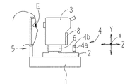
以下、本発明に係る実施形態を図面に基づいて説明する。図1は本実施形態に係る眼底撮影装置(以下、眼底カメラと記す)の外観構成図である。眼底カメラは、基台1と、基台1に対して左右方向(X方向)及び前後(作動距離)方向(Z方向)に移動可能な移動台2と、移動台2に対して3次元方向に移動可能に設けられ後述する光学系を収納する撮影部(装置本体)3と、回転ノブ4aと撮影スイッチ4bとを備えるジョイスティック4と、被検者の顔を支持するために基台1に固設された顔支持ユニット5を備える。撮影部3は、移動台2に設けられたXYZ駆動部6により、被検者眼Eに対して左右方向、上下方向(Y方向)及び前後方向に移動される。移動台2は、ジョイスティック4の操作により基台1上をXZ方向に移動される。また、回転ノブ4aを回転操作することにより、XYZ駆動部6がY駆動し、撮影部3がY方向に移動される。なお、撮影部3の検者側には、眼底観察像及び前眼部観察像等を表示するモニタ8が設けられている。
Embodiments according to the present invention will be described below with reference to the drawings. FIG. 1 is an external configuration diagram of a fundus imaging apparatus (hereinafter referred to as a fundus camera) according to the present embodiment. The fundus camera includes a
図2は本実施形態に係る眼底カメラの光学系の概略図である。光学系は、観察・撮影照明光学系10(観察照明光学系10a、撮影照明光学系10b)、眼底観察・撮影光学系30(眼底観察光学系30a、眼底撮影光学系30b)、フォーカス指標投影光学系40、アライメント指標投影光学系50、前眼部観察光学系60から大別構成されている。なお、図2の紙面左上には、アライメント指標投影光学系50を光軸L1方向から見たときの模式図を点線枠にて示している。
FIG. 2 is a schematic diagram of an optical system of the fundus camera according to the present embodiment. The optical system includes an observation / imaging illumination optical system 10 (observation illumination
<照明光学系> 観察照明光学系10aは、ハロゲンランプ等の可視から赤外域までの波長帯域を有する照明光源11、コンデンサレンズ13、リング状の開口を有するリングスリット17、リレーレンズ18、ミラー19、中心部に黒点を有する黒点板20、リレーレンズ21、孔あきミラー22、対物レンズ25を有する。撮影照明光学系10bは、フラッシュランプ等の可視光による撮影光源14、コンデンサレンズ15、リングスリット17から対物レンズ25までの光学系を有する。また、リングスリット17とコンデンサレンズ15との間にはエキサイタフィルタEXが挿脱機構Aにより光路から挿脱可能に配置されている。エキサイタフィルタEXは、約450nmから520nmの可視照明光を蛍光励起用光とする波長選択特性を有し、通常のカラー撮影時には光路から離脱された状態に置かれ、蛍光撮影時に挿入される。なお、エキサイタフィルタEXは、撮影光源14から穴あきミラー22までの撮影照明光学系10b上に配置することができる。
<Illumination Optical System> The observation illumination
<眼底観察・撮影光学系> 眼底観察光学系30aは、対物レンズ25、孔あきミラー22の開口近傍に位置する撮影絞り31、光軸方向に移動可能なフォーカシングレンズ32、結像レンズ33、挿脱機構39により光路から挿脱可能に位置された全反射ミラー34、赤外光から可視光までの波長帯域に感度を有する観察・撮影兼用の二次元撮像素子35、ミラー34の反射方向の光路にある全反射ミラー36、可視光にて検者が直接眼底を観察するための直視接眼レンズ38とからなる。
<Fundus Observation / Shooting Optical System> The fundus oculi observation
ミラー34が挿脱機構39により光路から離脱されることで、眼底からの反射光が撮像素子35で受光される。一方、挿脱機構39によりミラー34が光路に挿入されると、ミラー34で反射された可視光が、更にミラー36で反射されて接眼レンズ38に入射される。なお、撮影絞り31は対物レンズ25に関して被検者眼Eの瞳孔と略共役な位置に配置されている。フォーカシングレンズ32は、モータ(ステッピングモータ等)を備える移動機構49により光軸方向に移動される。
The
眼底撮影光学系30bは、眼底観察光学系30aの対物レンズ25と撮影絞り31から結像レンズ33までの光学系と、可視域から赤外域までに感度を持つ観察・撮影兼用の二次元撮像素子35を共用する。また、撮影絞り31とフォーカシングレンズ32との間には、バリアフィルタBAが挿脱機構Bにより光路から挿脱可能に配置されている。バリアフィルタBAは、蛍光撮影時に蛍光励起用光によって励起される蛍光のみを透過させ、その他の波長の光束を遮蔽させる特性を持ち、通常のカラー撮影時には光路から離脱された状態に置かれ、蛍光撮影時に挿入される。このような、バリアフィルタBAは眼底撮影光学系30bにおいて、前眼部観察光学系60と照明光学系10と共有の光路を避けた、孔あきミラー22から撮像素子35までの光路上に配置することができる。
The fundus photographing
孔あきミラー22の穴周辺には、被検者眼の角膜上に光学アライメント指標(ワーキングドットW1)を形成するための、2つの点光源70が光軸L1を中心に左右対称に配置される。点光源70は例えば光ファイバの出射端にて形成されており、光ファイバは図示なきハロゲンランプからの光を孔あきミラー22まで導光している。点光源70による角膜反射光は、被検者眼Eと撮影部3(装置本体)との作動距離が適切になったとき、眼底と略共役位置に配置された撮像素子35の撮像面上に結像するようになっており、被検者眼の眼底を観察しながらアライメントの微調整を行うための指標投影光学系として用いられる。この場合、眼底観察光学系30aは、点光源70による角膜反射像を撮像素子35に導く役割を兼用する。
Around the hole of the
対物レンズ25と孔あきミラー22の間には、光路分岐部材としてのダイクロイックミラー(波長選択性ミラー)24が、ソレノイドとカム等により構成される挿脱機構66により光路から挿脱可能に斜設されている。ここで、図5にダイクロイックミラー24の波長透過特性を示す。ダイクロイックミラー24は、赤外域の波長光(中心波長880nmを含む900nm以下の赤外光)を透過させ、これ以外の波長帯域の光束(赤外光及び可視光)を反射させる特性を有する。なお、ダイクロイックミラー24は、観察・撮影照明光学系10、フォーカス視標投影光学系40、光源70の共通の光路上に挿脱可能に設けることができる。
Between the
<アライメント指標投影光学系> アライメント用指標光束を投影するアライメント指標投影光学系50には、図2の紙面の点線枠内の図に示すように、撮影光軸L1を中心として同心円上に45度間隔で赤外光源が複数個配置されており、撮影光軸L1を通る垂直平面を挟んで左右対称に配置された赤外光源51とコリメーティングレンズ52を持つ第1指標投影光学系(0度、及び180)と、第1指標投影光学系とは異なる位置に配置され6つの赤外光源53を持つ第2指標投影光学系と、を備える。この場合、第1指標投影光学系は被検眼Eの角膜に無限遠の指標を左右方向から投影し、第2指標投影光学系は被検眼Eの角膜に有限遠の指標を上下方向もしくは斜め方向から投影する構成となっている。なお、図2の本図には、便宜上、第1指標投影光学系(0度、及び180度)と、第2指標投影光学系の一部のみ(45度、135度)が図示されている。
なお、本実施形態では、光源51及び53は中心波長940nmの赤外光を照射するものが使用される。これにより、光源51及び53からの光束はダイクロイックミラー24で反射されて、撮像素子65で撮像されるようになる。
<Alignment Index Projection Optical System> The alignment index projection
In the present embodiment,
<前眼部観察光学系> 前眼部観察光学系60は、ダイクロイックミラー24の反射側に、フィールドレンズ61、ミラー62、絞り63、リレーレンズ64、赤外域の感度を持つ撮影手段としての二次元撮像素子65を備える。また、二次元撮像素子65はアライメント指標検出用の撮像手段を兼ね、中心波長940nmの赤外光を発する前眼部照明光源58により照明された前眼部とアライメント指標が撮像される。前眼部照明光源58により照明された前眼部は、対物レンズ25、ダイクロイックミラー24及びフィールドレンズ61からリレーレンズ64の光学系を介して二次元撮像素子65で受光される。また、アライメント指標投影光学系50が持つ光源の点灯により、前眼部に投影されたアライメント指標が二次元撮像素子65に受光される。二次元撮像素子65の出力は制御部80に入力され、図3に示すようにモニタ8には二次元撮像素子65に撮像された前眼部像Fが表示される。なお、前眼部観察光学系60は、被検者眼Eに対する装置本体のアライメント状態を検出する役割を兼用する。
<Anterior Eye Observation Optical System> The anterior eye observation
<フォーカス指標投影光学系> フォーカス指標投影光学系40は、ハロゲンランプ等の可視から赤外域までの波長帯域の光束を照射する光源41、スリット指標板42、スリット指標板42に取り付けられた2つの偏角プリズム43、投影レンズ47、照明光学系10の光路に斜設されたスポットミラー44を備える。スポットミラー44はレバー45の先端に固着されていて、通常は光路に斜設されるが、撮影時にはロータリソレノイド46の軸の回転で、光路外に退避させられる。なお、スポットミラー44は被検者眼Eの眼底と共役な位置に配置される。光源41、スリット指標板42、偏角プリズム43、投影レンズ47、スポットミラー44及びレバー45は、フォーカシングレンズ32と連動して移動機構49により光軸方向に移動される。また、フォーカス指標投影光学系40のスリット指標板42の光束は、偏角プリズム43及び投影レンズ47を介してスポットミラー44により反射された後、リレーレンズ21、を介した後、孔あきミラー22にて反射される。
<Focus Index Projection Optical System> The focus index projection
以上のような構成によって、ダイクロイックミラー24とミラー34が光軸上で挿脱されることで、赤外光による眼底観察と可視光による眼底観察とを簡単に切換えることができるようになる。つまり、赤外光での眼底観察では、ダイクロイックミラー24が光路に挿入され、ミラー34を光路から退避される。これにより、観察照明光学系10aの光源11から発せられる可視域及び赤外域の光束のうち、所定の赤外域の波長光のみがダイクロイックミラー24を透過して、被検者眼Eの眼底を照明する。また、同様に、フォーカス視標投影光学系40の光源41から発せられる可視域及び赤外域の光束のうち、所定の赤外域の波長光のみがダイクロイックミラー24を透過して、眼底上に赤外光によるフォーカス指標であるスプリット指標S1・S2が形成される(図4参照)。なお、スプリット指標S1・S2を含む眼底からの反射光は、対物レンズ25、ダイクロイックミラー24等を通過して撮像素子35で結像される。
With the configuration described above, the
一方、可視光での眼底観察では、ダイクロイックミラー24が光路から退避され、ミラー34が光路に挿入される。これにより、光源11からの発せられる可視光(赤外域を含む)にて被検者眼Eの眼底が照明される。また、光源41からの可視光(赤外域を含む)によるスプリット指標S1・S2が眼底上に形成される。そして、スプリット指標S1・S2を含む眼底からの反射光は、対物レンズ25等を通過して、ミラー34、36で反射されて接眼レンズ38へと入射される。
On the other hand, in fundus observation with visible light, the
ところで、赤外光での眼底観察と可視光での眼底観察とを切換えるためにダイクロイックミラー24が光路上に挿脱されると、光路長(フォーカス状態)が変わってしまう。その為、眼底での位置合わせを可視光にて行う散瞳撮影と、赤外光で行う無散瞳撮影とでは光路長が変わるために、スプリット指標の合致点に光学的なずれが生じることになる。
By the way, when the
そこで、本実施形態では、ダイクロイックミラー24が離脱しておりスプリット指標S1・S2を検者が肉眼で確認する散瞳撮影(可視光)の眼底観察のときに、スプリット指標S1・S2の合致点とフォーカス視標光学系40のフォーカスが合った状態とが一致されるようにする。一方、無散瞳撮影(赤外光)の眼底観察では、ダイクロイックミラー24が光路上に挿入されているため、散瞳撮影に対してフォーカスの合致点に光学的なずれが生じることになる。そこで、ダイクロイックミラー24が離脱しているときにフォーカスが合った(スプリット指標が合致する)状態で、ダイクロイックミラー24が挿入されることによるスプリット指標S1・S2の分離(ずれ)量を予め合致基準情報としてメモリ85に記憶させておき、ダイクロイックミラー24が挿入された状態でフォーカス調整を行う場合に、メモリ85に記憶された合致基準情報に基づいてフォーカス調整の完了を判断できるようにする。
Therefore, in the present embodiment, when the fundus observation is performed for mydriatic photography (visible light) in which the
具体的には、フォーカシングレンズ32を光軸方向に移動させて自動的なフォーカス調整を行う場合に、逐次得られる撮像素子35上に結像されるスプリット指標(像)S1・S2の分離量がメモリ85に記憶されている合致基準情報(分離量)と一致したときのフォーカシングレンズ32の位置をフォーカス完了位置とする。また、手動にてフォーカス調整を行う場合には、メモリ85に記憶された合致基準情報を考慮して形成されたスプリット指標S11・S22をモニタ8に表示される赤外の眼底画像上に電子的に合成させ表示する。電子的に表示されるスプリット指標S11・S22は、撮像素子35上に結像されるスプリット指標(像)S1・S2の分離量がメモリに記憶されている合致基準情報(分離量)と一致したときに合致するように電子的に表示制御される。
Specifically, when automatic focusing is performed by moving the focusing
なお、本実施形態ではモニタに電子的にスプリット指標を表示させる例を示したが、これに限るものではなく、例えばインジケータ等のようにフォーカス調整が完了したか否かをモニタにて判断できるような指標を電子的に形成させることもできる。なお、ダイクロイックミラーを挿入することによるフォーカスのずれ(スプリット指標のずれ)量は、既知の度数(0D等)を持つ模型眼を用いて予め求めておくことができる。 In this embodiment, an example in which the split index is electronically displayed on the monitor is shown. However, the present invention is not limited to this. For example, the monitor can determine whether or not the focus adjustment has been completed, such as an indicator. Indices can also be formed electronically. The amount of focus shift (split index shift) caused by inserting a dichroic mirror can be obtained in advance using a model eye having a known power (0D or the like).
なお、本実施形態では、散瞳撮影と無散瞳撮影の複合型の眼底撮影装置の場合に、電子的なスプリット指標S11・S22をモニタ8に合成表示させる例を説明しているが、これに限られるものではない。例えば、被検者眼の位置合わせを赤外光で行い,可視光にて眼底撮影を行う無散瞳撮影用の眼底撮影装置において、観察用と撮影用の二次元撮像素子が共有されている場合に、電子的なスプリット指標S11・S22が使用されることで、より精度の高いフォーカス合わせができるようになる。
In the present embodiment, an example in which the electronic split indicators S11 and S22 are combined and displayed on the
<制御系> 二次元撮像素子65、35の出力は、制御部80に入力される。制御部80は二次元撮像素子65で撮像された前眼部画像からアライメント指標を検出処理する。これにより、制御部80は、撮像素子65からの撮影信号に基づいて被検者眼に対する装置本体3のアライメント偏位量を検出する。また、制御部80は、二次元撮像素子35で撮像された眼底画像からフォーカス指標であるスプリット指標S1・S2を検知し、撮像素子35からの撮影信号に基づいて装置本体のフォーカス状態の検出を行う。なお、アライメント偏位量の検出方法の詳細な説明は後述する。制御部80にはこれ以外にも、XYZ駆動部6、モニタ8、移動機構49、挿脱機構39、挿脱機構66、挿脱機構A,B、回転ノブ4a、撮影スイッチ4b、各種のスイッチを持つスイッチ部90、合致基準情報等の各種情報が記憶される記憶手段としてのメモリ85、上記に示す各光源等が接続されている。
<Control System> Outputs of the two-
また、制御部80は、図3の前眼部像観察画面示すように、アライメント基準となるレチクルLTを表示モニタ8の画面上の所定位置に電子的に形成して表示させるとともに,制御部80にて検出されたアライメント偏位量に基づいてレチクルLTとの相対距離を変化させるようにアライメント指標A1をモニタ8の画面上に電子的に形成して表示させる。また、制御部80は、図4の眼底観察画面に示すように、ワーキングドットW1を用いてXY方向のアライメントの微調整を行なうためのレチクルM1を表示させる。
Further, as shown in the anterior ocular segment image observation screen of FIG. 3, the
スイッチ部90には、被検者眼を無散瞳の状態で眼底観察を行う無散瞳モードと,被検者眼に散瞳剤を点眼して散瞳させた状態で眼底観察を行う散瞳撮影(散瞳モード)とを切換えるための無散瞳・散瞳切換スイッチ91と、前眼部のアライメントと眼底のフォーカスを自動的に調整するオートアライメント・フォーカスモードと,前眼部のアライメントと眼底のフォーカスを手動で調節する手動アライメント・フォーカスモードとを選択するスイッチ92、スイッチ91で散瞳モードが設定されたときに,眼底のカラー撮影を行うカラー撮影モードと眼底の蛍光撮影を行う蛍光撮影モードとを選択する切換スイッチ93、撮影可能条件が満たされたときに自動的に眼底撮影が行われる自動撮影モードと検者が撮影スイッチ4bを押す度に眼底撮影が行われる手動撮影モードとを選択するスイッチ94等が含まれる。
The switch unit 90 includes a non-mydriatic mode in which the fundus observation is performed with the subject's eye in a non-mydriatic state, and a non-mydriatic mode in which a mydriatic is applied to the subject's eye to make the mydriasis Non-mydriatic /
次に、以上のような構成を備える散瞳撮影・無散瞳撮影の複合型の眼底撮影装置において、無散瞳モードで眼底撮影を行う場合と、散瞳モードで蛍光撮影を行う場合の動作を説明する。始めに、無散瞳モードでの眼底撮影の動作を説明する。検者は被検者の顔を顔支持ユニット5で支持して、図示なき固視灯を固視させる(例えば、固視灯は被検者眼の眼前に配置される)。次に検者はスイッチ部90で撮影条件を設定する。ここでは、切換スイッチ91で無散瞳モードが選択され、スイッチ92でオートアライメント・フォーカスモード、スイッチ94で手動撮影モードが選択されるとする。
Next, in the combined fundus imaging device with mydriatic imaging / non-mydriatic imaging having the above-described configuration, the operation when performing fundus imaging in the non-mydriatic mode and when performing fluorescence imaging in the mydriatic mode Will be explained. First, the fundus photographing operation in the non-mydriatic mode will be described. The examiner supports the subject's face with the
制御部80はスイッチ91からの入力信号に基づき、挿脱機構66の駆動でダイクロイックミラー24を光路に挿入させ、挿脱機構39の駆動でミラー34を光路から退避させると共に、各光源を点灯させる。光源58で照明された被検者眼Eの前眼部からの反射光はダイクロイックミラー24で反射されて、二次元撮像素子65で撮像されてモニタ8に表示される。なお、前眼部像がモニタ8に現れていないときは、ジョイスティック4の操作で撮影部3を上下左右に移動させることでモニタ8に前眼部像を表示させれば良い。図3に示すように、前眼部像がモニタ8に現れるようになると、8つの指標像Ma〜Mhが現れるようになる。
Based on the input signal from the
前述のように被検者眼の角膜上に投影されたアライメント指標像は、二次元撮像素子65に検出されると、制御部80は、オートアライメント制御を開始する。制御部80は、二次元撮像素子65からの信号に基づいて被検眼に対する装置本体3のアライメント偏位量Δdを検出する。より具体的には、リング状に投影された指標像Ma〜Mhによって形成されるリング形状の中心のXY座標を略角膜中心として検出し、予め撮像素子65上に設定されたXY方向のアライメント基準位置O1(例えば、撮像素子65の撮像面と撮影光軸L1との交点)と角膜中心座標との偏位量Δdを求める(図6参照)。そして、制御部80は、この偏位量Δdがアライメント完了の許容範囲に入るように、XYZ駆動部6の駆動制御による自動アライメントを作動する。
As described above, when the alignment index image projected onto the cornea of the subject's eye is detected by the two-
また、制御部80は、無限遠の指標像Ma,Meの間隔と有限遠の指標像Mh,Mfの間隔とを比較することによりZ方向のアライメント偏位量を求める。この場合、制御部80は、装置本体3が作動距離方向にずれた場合に、前述の無限遠指標Ma,Meの間隔がほとんど変化しないのに対して、指標像Mh,Mfの像間隔が変化するという特性を利用して、被検眼に対する作動距離方向のアライメント偏位量を求める(詳しくは、特開平6−46999号参照)。
Further, the
また、制御部80は、Z方向についても、Z方向のアライメント基準位置に対する偏位量を求め、その偏位量がアライメントが完了したとされるアライメント許容範囲に入るように、XYZ駆動部6の駆動制御による自動アライメントを作動する。被検者眼に対する自動アライメントが行われると、モニタ8上におけるアライメント基準位置近傍(レチクルLTの中心)に被検眼の角膜頂点(又は瞳孔中心)が位置された状態になる。
In addition, the
また、観察撮影光学系10aの照明光源11の点灯により、光源11から照射された光束がダイクロイックミラー24に入射される。この時、光束に含まれる中心波長880nmを含む900nm以下の赤外光成分は、ダイクロイックミラー24を透過して、対物レンズ25により被検者眼Eの瞳孔付近で一旦収束した後、拡散して被検者眼Eの眼底部を照明する。この赤外光による眼底からの反射光は、対物レンズ25、ダイクロイックミラー24を透過して、穴あきミラー22の開口部を通過し、撮影絞り31、フォーカシングレンズ23、撮像レンズ33を介して、撮像素子35に結像される。一方、照明光源11からの可視光を含む上記の波長成分以外の光束はダイクロイックミラー24により光路外へと反射される。
Further, the
更に、フォーカス指標投影光学系40光源41の点灯により、中心波長880nmを含む900nm以下の赤外光がダイクロイックミラー24を透過して、被検者眼Eの眼底にスプリット指標S1・S2を投影する。スプリット指標S1・S2の反射光は再びダイクロイックミラー24を透過して撮像素子35で結像される。撮像素子35で光学的なスプリット指標S1・S2が検出されると、制御部80は、スプリット指標像S1・S2の分離状態とメモリ85に記憶されている合致基準情報とを比較することによりフォーカス状態を得る。そして制御部80はスプリット指標S1・S2のずれ量が合致基準情報と同じずれ量となるように移動機構49の駆動によりフォーカシングレンズ32を光軸L1上で移動させて、フォーカス調整を自動的に行う。
Furthermore, by turning on the light source 41 of the focus index projection
図4(a)は撮像素子35で撮像された眼底像(眼底の観察像)のモニタ8での表示例であり、図4(b)は遮光領域145の先端付近の拡大図である。眼底像上には、光源70からの光束のうち、図5に示される赤外光の波長成分がダイクロイックミラー24を透過することで、角膜反射光(赤外光)による2つのワーキングドットW1が眼底観察画像に重畳して現れる。また、眼底像上には、観察・撮影照明光学系10の光路に挿入されたレバー45によって観察光束が遮光されることで形成される遮光領域145が表示される。また、本実施形態では、遮光領域145上には、上述したスプリット指標S11・S22が表示される。この電子的に形成されたスプリット指標S11・S22は、手動によるフォーカス調整に用いられることとなる。なお、制御部80は、光学的に検出されたスプリット指標像S1・S2にレバー45の遮光領域145と表示状態(色合い等)を一致させる画像処理を行うことで、モニタ8上で視認されにくくしている。
4A is a display example of the fundus image (observation image of the fundus) captured by the
検者は、モニタ8を確認しながら、必要であれば、ジョイスティック4にて、ワーキングドットW1が表示モニタ8の画面の中心に対して左右対称に電子的(電気的)に形成されたレチクルM1に一致するように、XY方向のアライメントの微調整を行うと共に、ワーキングドットW1のピントが合うようにZ方向の微調整を行う。また、図示を略すフォーカスノブの操作で、スプリット指標S11・S22が一致するように調整する。なお、本実施形態では、光源70により光学的に検知されるワーキングドットW1に基づきZ方向(作動距離方向)の微調整を行っているが、これ以外にも、前眼部観察光学系60で検出されたアライメント情報に基づき電子的なスプリット指標を表示させることで、Z方向の微調節が行われるようにしても良い。
The examiner checks the
以上のように、眼底を観察しながらの被検者眼Eと撮影部3とのアライメント及びフォーカスの微調整の完了後、制御部80は撮影スイッチ4bからのトリガ信号に基づき眼底撮影を行う。なお、スイッチ94で自動撮影モードが設定されている場合には自動的に眼底撮影が行われる。
As described above, after the alignment between the subject eye E and the imaging unit 3 while observing the fundus and the fine adjustment of the focus are completed, the
撮影開始信号の入力により、制御部80は、撮影光源14を発光させる。また、制御部80は撮影光源14の発光に連動させて、挿脱機構66の駆動によりダイクロイックミラー24を光路から退避させると共に、光源41等の撮影に不必要な光源を消灯させる。これにより、被検者眼Eの眼底が可視光により照明され、眼底からの反射光が撮像素子35で撮像される。
In response to the input of the imaging start signal, the
次に、散瞳モードでの蛍光撮影について説明する。ここでは、検者によりスイッチ91で散瞳モード、スイッチ92でオートアライメント・フォーカスモード、スイッチ93で蛍光撮影モード、スイッチ94で手動撮影モードが選択されたとする。制御部80はスイッチ部90からの入力信号に基づき、無散瞳モードの場合と同様に、挿脱機構66によりダイクロイックミラー24を眼底観察・撮影光学系30の光路に挿入すると共に、挿脱機構39によりミラー34を光路から退避させる。そして、各光源を点灯させる。これにより、散瞳撮影でも赤外光を用いたオート又は手動による,アライメント及びフォーカス調整が出来るようになる。
Next, fluorescence imaging in the mydriatic mode will be described. Here, it is assumed that the examiner selects the mydriatic mode with the
被検者眼に散瞳剤を点眼して十分に散瞳させた後、検者は被検者に蛍光剤(例えば、フルオレセインナトリウム)を静注する。その後、被検者の顔を顔支持ユニット5により支持し、図示なき固視灯を固視させる(例えば、固視灯は被検者眼の眼前に配置される)。この時、ダイクロイックミラー24は撮影光学系30の光路に挿入されており、光源58で照明された前眼部像が二次元撮像素子65で撮像されてモニタ8に表示され、アライメント指標像Ma〜Mhも現れるようになる(図3参照)。
After the patient's eyes are instilled with a mydriatic agent and sufficiently dilated, the examiner intravenously injects a fluorescent agent (for example, fluorescein sodium) to the subject. Thereafter, the face of the subject is supported by the
また、照明光源11及び光源41の点灯により、図5に示す波長の赤外光がダイクロイックミラー24を透過して眼底に入射される。そして、眼底からの反射光が撮像素子35で受光されることで、赤外光にて眼底像及びスプリット指標S1・S2が検出された状態となる。制御部80は撮像素子65によるアライメント指標の検出結果に基づいて被検者眼に対して眼底撮影光学系30bの位置を自動的に調整するオートアライメントを開始すると共に、撮像素子35によるフォーカス視標の検出結果に基づきオートフォーカスを開始する。
Further, when the
なお、前述した無散瞳モードでの眼底撮影の場合と同様に、オートアライメントが完了され、オートフォーカスが合致基準情報を満たす状態となったら、制御部80は挿脱機構66によりダイクロイックミラー24を光路から退避させると共に、挿脱機構39の駆動でミラー34を光路に挿入させる。これにより、被検者眼の眼底が可視光で照明され、接眼レンズ38を介して直接眼底観察を行うことができるようになる。また、制御部80は、ダイクロイックミラー24の退避と連動させて、前眼部観察光学系60によるオートアライメントと、フォーカス指標投影光学系40によるオートフォーカスを停止させる。
As in the case of fundus photographing in the non-mydriatic mode described above, when the auto alignment is completed and the autofocus satisfies the matching reference information, the
眼底からの可視光による反射光は、対物レンズ25を通過し、ミラー34、36で反射されて、接眼レンズ38へと入射される。このとき、可視光のスプリット視標S1・S2と、ワーキングドットW1とが接眼レンズ38を介して確認されるので、検者は可視で見易い状態のスプリット視標S1・S2によるフォーカスの微調整と、ワーキングドットW1による作動距離方向の微調整を行うことができる。
The reflected light by the visible light from the fundus passes through the
なお、ここでは、上記の無散瞳モードと同様に、アライメントとフォーカスの調整が制御部80により自動的に行われる場合を例に挙げて説明しているが、これに限られるものではない。前眼部観察光学系60によるアライメントと、眼底観察光学系40によるフォーカス調整とを手動で行う場合には、例えば、検者はジョイスティック4の操作で手動にてアライメント調整を行い、図示を略すフォーカスノブで手動にてフォーカス調整を完了させる。そして、図示を略すスイッチの操作により、ダイクロイックミラー24を光路から挿脱させるようにすれば良い。
Here, as in the non-mydriatic mode described above, the case where alignment and focus adjustment are automatically performed by the
撮影スイッチ4が押されると、制御部80は、エキサイタフィルタEX及びバリアフィルタBAをそれぞれ光路上に挿入させる。そして、撮影光源14を発光させる。撮影光源14からの可視光はエキサイタフィルタEXにより蛍光励起光である青色光に制限され、前述の光路を辿って被検者眼の眼底を照明する。励起光による眼底からの反射光自体はバリアフィルタBAにより完全に遮断される。眼底血管に循環した蛍光剤が励起光により励起され、520nmを超える帯域(可視光)の蛍光が発せられる。この蛍光光束は対物レンズ25、穴あきミラー22、絞り31を通過してバリアフィルタBAを通過する。その後、フォーカシングレンズ33を介して、二次元撮像素子35の撮像面上に結像され、これにより、蛍光光束による眼底血管造影が撮像される。撮像された眼底血管造影画像(蛍光画像)はメモリ85に記憶されるとともに、モニタ8に表示される。
When the photographing
なお、蛍光撮影は、蛍光剤投与から眼底に蛍光剤が現れるまでの期間(約8〜15秒後)、蛍光剤が最初に一巡され、脈絡膜・網膜血管が良く観察される期間(約20〜30秒後)、蛍光剤が再び眼底に出現され、蛍光画像により機能(血液網膜関門)異常をよく観察できる期間(約10〜40分後)で行われ、撮影スイッチ4を押すことで、連続的に眼底画像を得ることができる。なお、撮像された眼底画像はモニタ8に更新表示されるので、連続撮影中の蛍光画像の変化を容易に確認できる。
Fluorescence imaging is a period from the administration of the fluorescent agent to the appearance of the fluorescent agent in the fundus (after about 8 to 15 seconds), a period in which the fluorescent agent is first cycled and the choroid / retinal blood vessels are well observed (about 20 to about 20 to (After 30 seconds), the fluorescent agent appears again on the fundus, and it is performed in a period (after about 10 to 40 minutes) in which the function (blood-retinal barrier) abnormality can be well observed by the fluorescence image. Thus, a fundus image can be obtained. Since the captured fundus image is updated and displayed on the
以上のような構成にすることで、散瞳撮影と無散瞳撮影の両方で赤外光によるアライメントを行うことができるようになり、散瞳モードの場合に被検者眼に可視光が長時間照射されることによる負担を少なくすることができる。 With the above configuration, infrared light alignment can be performed in both mydriatic and non-mydriatic photography, and visible light is long in the subject's eye in the mydriatic mode. The burden due to the time irradiation can be reduced.
また、散瞳モードと無散瞳モードのアライメントが前眼部観察光学系を用いた赤外光によるアライメントに統一されるので、簡単な構成で操作性のよい眼底撮影装置を提供することができるようになる。 In addition, since the alignment of the mydriatic mode and the non-mydriatic mode is unified to the alignment by infrared light using the anterior ocular segment observation optical system, it is possible to provide a fundus photographing apparatus with a simple configuration and good operability. It becomes like this.
また、散瞳撮影と無散瞳撮影の複合機で、光学部材の挿脱により散瞳撮影と無散瞳撮影とを切換える場合に、フォーカシングレンズの位置に合わせて電子的に補正したスプリット指標を用いることで、フォーカス視標を用いてより精度の高いフォーカス合わせをすることができるようになる。 In addition, when using a combination of mydriatic and non-mydriatic photography to switch between mydriatic photography and non-mydriatic photography by inserting / removing an optical member, a split index that is electronically corrected according to the position of the focusing lens is used. By using it, it becomes possible to perform focusing with higher accuracy using the focus target.
8 モニタ
10 観察・撮影照明光学系
11、14、41、51、53、58、70 光源
24 ダイクロイックミラー
30 眼底観察・撮影光学系
35、65 撮像素子
38 接眼レンズ
40 フォーカス指標投影光学系
50 アライメント指標投影光学系
60 前眼部観察光学系
80 制御部
8
Claims (4)
可視光を用いて観察を行うための散瞳用の光学系とを有する眼底撮影装置において、
赤外光によるアライメント指標を被検者眼に投影するアライメント指標投影光学系と、
被検者眼に投影された前記アライメント指標の受光状態に基づいて被検者眼と装置とのアライメントを行うためのアライメント制御手段と、
散瞳型撮影モードと無散瞳型撮影モードとを選択するためのモード選択手段と、
前記散瞳型撮影モードが選択されている場合に前記アライメント制御手段により所定のアライメント状態が得られた後,被検者眼に向けて照射する照明用の光を赤外光から可視光に切り換える照明光切換手段と、
を有することを特徴とする眼底撮影装置。 A non-mydriatic optical system for observation using infrared light; and
In a fundus imaging apparatus having a mydriatic optical system for performing observation using visible light,
An alignment index projection optical system for projecting an alignment index by infrared light onto the subject's eye;
An alignment control means for performing alignment between the subject's eye and the device based on the light receiving state of the alignment index projected onto the subject's eye;
Mode selection means for selecting a mydriatic type photographing mode and a non-mydriatic type photographing mode;
When the mydriatic imaging mode is selected, after the predetermined alignment state is obtained by the alignment control means, the illumination light irradiated toward the subject's eye is switched from infrared light to visible light Illumination light switching means;
A fundus photographing apparatus comprising:
前記無散瞳用光学系と前記散瞳用光学系の共通の光学系として,可視域及び赤外域の光を発する光源を持ち該光源から発せられる光を被検者眼に向けて導光させる光学系を持つ照明光学系と、
該照明光学系により照明された被検者眼の眼底を撮像する第1撮影手段を持つ眼底観察光学系と、前記アライメント指標投影光学系によりアライメント指標が投影された被検者眼の前眼部を撮像する第2撮影手段を持つ前眼部観察光学系と、
該前眼部観察光学系の光路の一部と前記照明光学系の光路の一部とを同軸とするために前記照明光学系の光路に挿脱可能に配置されるダイクロイックミラーであって,前記アライメント指標を反射させて前記前眼部観察光学系に導光させるとともに前記アライメント指標の波長以外の他の赤外光の少なくとも一部の波長域を透過させるダイクロイックミラーと、を有し、
前記照明光切換手段は前記ダイクロイックミラーを光路から挿脱させることにより赤外光と可視光とを切り換えることを特徴とする眼底撮影装置。 The fundus imaging apparatus according to claim 1,
As a common optical system for the non-mydriatic optical system and the mydriatic optical system , it has a light source that emits light in the visible region and infrared region, and guides the light emitted from the light source toward the eye of the subject. An illumination optical system having an optical system;
A fundus oculi observation optical system having first imaging means for imaging the fundus of the subject's eye illuminated by the illumination optical system, and an anterior segment of the subject's eye on which an alignment index is projected by the alignment index projection optical system An anterior ocular segment observation optical system having second imaging means for imaging
A dichroic mirror disposed so as to be detachable from the optical path of the illumination optical system so that a part of the optical path of the anterior ocular segment observation optical system and a part of the optical path of the illumination optical system are coaxial; A dichroic mirror that reflects the alignment index and guides it to the anterior ocular segment observation optical system and transmits at least a part of the wavelength range of infrared light other than the wavelength of the alignment index; and
The fundus photographing apparatus characterized in that the illumination light switching means switches between infrared light and visible light by inserting and removing the dichroic mirror from the optical path.
可視から赤外域の波長の光を発する第2の光源を持ち該第2光源からの光をフォーカス指標として被検者眼眼底に向けて投影するためのフォーカス指標投影光学系を備え、
前記フォーカス指標は前記ダイクロイックミラーの挿入時には該ダイクロイックミラーを介することにより赤外域の波長のフォーカス指標として被検者眼眼底に投影され、前記ダイクロイックミラーの離脱時には可視域の波長のフォーカス指標として被検者眼眼底に投影されることを特徴とする眼底撮影装置。 The fundus imaging apparatus according to claim 2 comprises:
A focus index projection optical system having a second light source that emits light having a wavelength in the visible to infrared range, and projecting light from the second light source toward the fundus of the subject's eye as a focus index;
When the dichroic mirror is inserted, the focus index is projected onto the fundus of the subject's eye through the dichroic mirror, and when the dichroic mirror is detached, the focus index is projected as the focus index of the visible wavelength. A fundus imaging apparatus that projects onto the fundus of the human eye.
前記第1撮影手段は可視域から赤外域まで感度を持つ撮像素子であることを特徴とする眼底撮影装置。 The fundus imaging apparatus according to claim 3,
The fundus imaging apparatus, wherein the first imaging means is an imaging device having sensitivity from a visible range to an infrared range.
Priority Applications (1)
| Application Number | Priority Date | Filing Date | Title |
|---|---|---|---|
| JP2010083567A JP5522629B2 (en) | 2010-03-31 | 2010-03-31 | Fundus photographing device |
Applications Claiming Priority (1)
| Application Number | Priority Date | Filing Date | Title |
|---|---|---|---|
| JP2010083567A JP5522629B2 (en) | 2010-03-31 | 2010-03-31 | Fundus photographing device |
Publications (3)
| Publication Number | Publication Date |
|---|---|
| JP2011212241A JP2011212241A (en) | 2011-10-27 |
| JP2011212241A5 JP2011212241A5 (en) | 2013-05-16 |
| JP5522629B2 true JP5522629B2 (en) | 2014-06-18 |
Family
ID=44942626
Family Applications (1)
| Application Number | Title | Priority Date | Filing Date |
|---|---|---|---|
| JP2010083567A Active JP5522629B2 (en) | 2010-03-31 | 2010-03-31 | Fundus photographing device |
Country Status (1)
| Country | Link |
|---|---|
| JP (1) | JP5522629B2 (en) |
Families Citing this family (2)
| Publication number | Priority date | Publication date | Assignee | Title |
|---|---|---|---|---|
| CN104257345B (en) * | 2014-09-17 | 2016-09-14 | 夏明亮 | A kind of lighting unit, imaging system and using method thereof |
| CN107405070B (en) * | 2015-02-27 | 2019-05-21 | 兴和株式会社 | Eyeground camera system |
-
2010
- 2010-03-31 JP JP2010083567A patent/JP5522629B2/en active Active
Also Published As
| Publication number | Publication date |
|---|---|
| JP2011212241A (en) | 2011-10-27 |
Similar Documents
| Publication | Publication Date | Title |
|---|---|---|
| JP4231146B2 (en) | Fundus camera | |
| US7364295B2 (en) | Fundus camera | |
| JP4138533B2 (en) | Fundus camera | |
| JP5772117B2 (en) | Fundus photographing device | |
| JP5101370B2 (en) | Fundus photographing device | |
| JP4359489B2 (en) | Fundus camera | |
| JP5554610B2 (en) | Fundus photographing device | |
| JP5427494B2 (en) | Fundus photographing device | |
| JP4268861B2 (en) | Fundus camera | |
| JP2007275160A (en) | Ophthalmologic apparatus | |
| JP5435698B2 (en) | Fundus camera | |
| JP4886388B2 (en) | Fundus camera | |
| JP5545982B2 (en) | Fundus camera | |
| JP4886387B2 (en) | Fundus camera | |
| JP4359527B2 (en) | Fundus camera | |
| JP4774305B2 (en) | Fundus camera | |
| JP4886389B2 (en) | Fundus camera | |
| JP5522629B2 (en) | Fundus photographing device | |
| JP5328517B2 (en) | Fundus photographing device | |
| JP5807701B2 (en) | Fundus photographing device | |
| JP6292331B2 (en) | Fundus photographing device | |
| JP4615891B2 (en) | Fundus camera | |
| JP4481727B2 (en) | Fundus camera | |
| JP6107906B2 (en) | Fundus photographing device | |
| JP2006116089A (en) | Fundus camera |
Legal Events
| Date | Code | Title | Description |
|---|---|---|---|
| A521 | Written amendment |
Free format text: JAPANESE INTERMEDIATE CODE: A523 Effective date: 20130328 |
|
| A621 | Written request for application examination |
Free format text: JAPANESE INTERMEDIATE CODE: A621 Effective date: 20130328 |
|
| A977 | Report on retrieval |
Free format text: JAPANESE INTERMEDIATE CODE: A971007 Effective date: 20140225 |
|
| TRDD | Decision of grant or rejection written | ||
| A01 | Written decision to grant a patent or to grant a registration (utility model) |
Free format text: JAPANESE INTERMEDIATE CODE: A01 Effective date: 20140311 |
|
| A61 | First payment of annual fees (during grant procedure) |
Free format text: JAPANESE INTERMEDIATE CODE: A61 Effective date: 20140401 |
|
| R150 | Certificate of patent or registration of utility model |
Ref document number: 5522629 Country of ref document: JP Free format text: JAPANESE INTERMEDIATE CODE: R150 |
|
| R250 | Receipt of annual fees |
Free format text: JAPANESE INTERMEDIATE CODE: R250 |
|
| R250 | Receipt of annual fees |
Free format text: JAPANESE INTERMEDIATE CODE: R250 |
|
| R250 | Receipt of annual fees |
Free format text: JAPANESE INTERMEDIATE CODE: R250 |