EP1079622A2 - Apparatus and method for adjusting convergence utilizing spine interpolation - Google Patents
Apparatus and method for adjusting convergence utilizing spine interpolation Download PDFInfo
- Publication number
- EP1079622A2 EP1079622A2 EP00117942A EP00117942A EP1079622A2 EP 1079622 A2 EP1079622 A2 EP 1079622A2 EP 00117942 A EP00117942 A EP 00117942A EP 00117942 A EP00117942 A EP 00117942A EP 1079622 A2 EP1079622 A2 EP 1079622A2
- Authority
- EP
- European Patent Office
- Prior art keywords
- convergence
- adjustment
- point
- points
- spline interpolation
- Prior art date
- Legal status (The legal status is an assumption and is not a legal conclusion. Google has not performed a legal analysis and makes no representation as to the accuracy of the status listed.)
- Withdrawn
Links
Images



Classifications
-
- H—ELECTRICITY
- H04—ELECTRIC COMMUNICATION TECHNIQUE
- H04N—PICTORIAL COMMUNICATION, e.g. TELEVISION
- H04N5/00—Details of television systems
- H04N5/74—Projection arrangements for image reproduction, e.g. using eidophor
-
- H—ELECTRICITY
- H04—ELECTRIC COMMUNICATION TECHNIQUE
- H04N—PICTORIAL COMMUNICATION, e.g. TELEVISION
- H04N9/00—Details of colour television systems
- H04N9/12—Picture reproducers
- H04N9/16—Picture reproducers using cathode ray tubes
- H04N9/28—Arrangements for convergence or focusing
-
- H—ELECTRICITY
- H04—ELECTRIC COMMUNICATION TECHNIQUE
- H04N—PICTORIAL COMMUNICATION, e.g. TELEVISION
- H04N5/00—Details of television systems
- H04N5/74—Projection arrangements for image reproduction, e.g. using eidophor
- H04N5/7408—Direct viewing projectors, e.g. an image displayed on a video CRT or LCD display being projected on a screen
Definitions
- the present invention relates generally to a projection image display device, and in particular, to an apparatus and method for adjusting convergence utilizing spline interpolation.
- the current real time digital convergence system uses a fourth-order Lagrange polynomial with 5 ⁇ 5 seed data to achieve horizontal and vertical lines by interpolation.
- the reason for using the fourth-order function is that the CRT surface of a projection TV is made non-spherical to increase illumination efficiency, as shown in FIG. 1.
- To make smooth curvature out of the surface of the CRT five points with brusque curvature changes are selected as seed points (a) and subjected to convergence adjustment in a fourth-order Lagrange interpolation polynomial.
- FIG. 1 illustrates an example of a horizontal CRT non-spherical surface and seed/non-seed data ((a)/(b)) and FIG.
- FIG. 2 is a point connection state diagram referred to for describing the influence of a variation in convergence data at a seed point (c) on convergence data at other seed points.
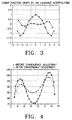
- FIG. 3 is an exemplary graph obtained by a Lagrange interpolation and
- FIG. 4 is a graph showing variations in convergence data at other seed points caused by the variation of convergence data at one specific seed point in Lagrange interpolation.
- One of the benefits of using the fourth-order Lagrange interpolation polynomial is that no density modulation occurs at seed points (3, 6, 9, 12, and 15 in FIG. 1.
- Another benefit is that a look-up table is used instead of complicated hardware in calculating coefficients of the Lagrange polynomial, thereby facilitating simplification of hardware and enabling real time processing.
- the fourth-order Lagrange interpolation polynomial has the distinctive drawback that adjustment of convergence data at one seed point influences convergence data at other seed points. For example, if convergence data at point 9 on a first horizontal line is adjusted to (c), convergence data at its adjacent points are also changed in FIG. 2. While one line only is shown to be influenced in FIG. 2, all data in horizontal and vertical lines are changed at worst and, as a result, the whole image may be changed. Furthermore, density modulation may take place at end seed points 3 and 15 due to external points 1, 2, and 16 obtained by piecewise linear interpolation in the horizontal direction instead of Lagrange interpolation.
- an object of the present invention to provide a convergence adjustment apparatus and method which can solve the above-described problems encountered in using a fourth-order Lagrange interpolation polynomial, by use of cubic spline interpolation.
- a controller calculates the unknown coefficients of a cubic spline interpolation polynomial for each line segment separated by adjustment points on a horizontal or vertical line to interpolate between the adjustment points, a memory temporarily stores the unknown coefficients, a coordinate position generator counts horizontal sync signal pulses and calculates the square and cube of the count value, a plurality of multipliers multiply the count value, the square, and the cube by the unknown coefficients received from the memory, respectively, and an adder adds convergence adjustment point data received from the memory and the outputs of the multipliers and outputs interpolation values.
- the third-order polynomial has four unknown coefficients, two of them can be obtained only if the third-order polynomial passes through two points, and the other two coefficients can be obtained when first and second differential values of the polynomial are connected at two given points.
- the cubic spline interpolation polynomial can be simplified in the following way.
- a j0 is a function value at an adjustment point and a j1 is the slope at the intended point, obtained in Eq. 4.
- a j0 and a j1 will be termed Y 0 and K 1 hereinbelow.
- the other unknown coefficients a j0 and a j1, which can be calculated if the function value and the slope are given, are termed A 12 and A 1 3, respectively.
- h in Eq. 5 is assumed to the interval between adjacent points and the same between any pair of adjacent points. Eqs.
- Hardware can be more simplified using the cubic spline interpolation polynomial of Eq. 8 than using the fourth-order Lagrange polynomial.
- the cubic spline interpolation polynomial can be implemented in hardware as shown in FIG. 5 and a CPU (Central Processing Unit) 100 calculates the unknown coefficients Y 0 , K 1 , A 12 , and A 13 of the cubic spline interpolation polynomial for convergence adjustment.
- a CPU Central Processing Unit
- Multi-spline interpolation refers to spline interpolation that is performed on a line segment including an intended adjustment point y and other adjacent line segments. For example, if a third point y_2 is to be adjusted in four line segments separated by five points, primary interpolation is implemented between second and third points and between third and fourth points to change values between second and third line segments and then secondary interpolation is performed in such a way that the value between the first and fourth line segments is changed.
- the convergence of an intended line segment can be adjusted with minimum influence on the convergence of the whole image.
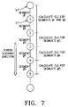
- FIG. 6 is a block diagram of the convergence adjustment apparatus according to the embodiment of the present invention and FIG. 7 is a flowchart illustrating the multi-spline interpolation procedure according to the embodiment of the present invention.
- the convergence adjustment apparatus is comprised of a CPU 100, a RAM (Random Access Memory) 110, multipliers 130, 140, and 150, an adder 160, and a coordinate position (X) generator 120.
- the CPU 100 calculates the unknown coefficients Y 0 , K 1 , A 12 , and A 13 of a cubic spline interpolation polynomial for each line segment defined by convergence adjustment points to interpolate between each pair of convergence adjustment points and stores them in the RAM 110.
- Convergence adjustment data input to the CPU 100 has been changed by an operator.
- the unknown coefficient Y 0 (function value) at the adjustment point is changed.
- the coordinate position generator 120 counts horizontal sync signal pulses H-syn and outputs the count of horizontal lines.
- the coordinate position generator 120 also generates the square and cube of the horizontal line count. This coordinate position generator 120 is reset by a vertical sync signal V-syn.
- the multipliers 130, 140, and 150 multiply the horizontal line count, its square, and its cube received from
- a controller calculates the unknown coefficients of a cubic spline interpolation polynomial for each line segment separated by adjustment points on a horizontal or vertical line to interpolate between the adjustment points, a memory temporarily stores the unknown coefficients, a coordinate position generator counts horizontal sync signal pulses and calculates the square and cube of the count value, a plurality of multipliers multiply the count value, the square, and the cube by the unknown coefficients received from the memory, respectively, and an adder adds convergence adjustment point data received from the memory and the outputs of the multipliers and outputs interpolation values.
- the coordinate position generator 120 by the unknown coefficients K 1 , A 12 , and A 13.
- the adder 160 adds the outputs of the RAM 110 and the multipliers 130, 140, and 150 and outputs interpolation data between adjustment points by the cube spline interpolation polynomial f(x). Referring to the interpolation data, current applied to a deflection coil of an R.G.B CRT is controlled for adjustment of R.G.B. convergence.
- the CPU 100 calculates a value between a starting adjustment point S.P among five convergence adjustment points that form a vertical line and a virtual point V.P above the starting adjustment point and a value between the starting adjustment point and a second adjustment point below the first adjustment point, by the cube spline interpolation polynomial f(x).
- the unknown coefficients Y 0 , K 1 , A 12 , and A 13 of cube spline interpolation polynomials f(x) for line segments # 1 and #2 are calculated with convergence adjustment data in Eqs. 4 and 5.
- the CPU 100 calculates a value between the second adjustment point and a third adjustment point below the second adjustment point by a cube spline interpolation polynomial f(x).
- the interpolation value between the first and second adjustment points is used as the interpolation value in line segment #2.
- a value between the third adjustment point and a fourth adjustment point below the third adjustment point is calculated by a cube spline interpolation polynomial f(x). That is, the CPU 100 calculates a single-directional function continuously without the need for using two functions for one point with respect to its adjacent points, so that piecewise functions are connected to one whole function on a vertical or horizontal line.
- the convergence of an intended line segment can be efficiently adjusted, having a minimum influence on the convergence of the entire image.
- the change of convergence data at points other than specific adjustment points is minimized by interpolating between adjustment points by spline interpolation for line segments including the adjustment points. Because the CPU performs spline interpolation calculations, the interpolation data between intended adjustment points can be obtained with simple hardware. Furthermore, only the convergence of an intended line segment can be adjusted with an influence on the convergence of the entire image minimized, by ensuring the continuity of a vertical or horizontal line.
Landscapes
- Engineering & Computer Science (AREA)
- Multimedia (AREA)
- Signal Processing (AREA)
- Video Image Reproduction Devices For Color Tv Systems (AREA)
Abstract
Description
Claims (2)
- A convergence adjusting apparatus in a projection image display device, comprising:a controller for calculating the unknown coefficients of a cubic spline interpolation polynomial for each line segment separated by adjustment points on a horizontal or vertical line to interpolate between the adjustment points;a memory for temporarily storing the unknown coefficients;a coordinate position generator for counting horizontal sync signal pulses and calculating the square and cube of the count value;a plurality of multipliers for multiplying the count value, the square, and the cube by the unknown coefficients received from the memory, respectively; andan adder for convergence adjustment point data received from the memory and the outputs of the multipliers and outputting interpolation values.
- A convergence adjusting method in a projection image display device, comprising the steps of:(1) setting a specific adjustment point on a horizontal or vertical line as a starting point and calculating a value between the starting point and adjacent points using a cubic spline interpolation polynomial;(2) setting one of the adjacent points as a second point and calculating a value between the second point and a point adjacent to the second point using a cubic spline interpolation polynomial; and(3) repeating the step (2) until cubic spline interpolation is performed between all adjustment points in one direction from the starting point,
whereby convergence is adjusted on the horizontal or vertical line.
Applications Claiming Priority (2)
| Application Number | Priority Date | Filing Date | Title |
|---|---|---|---|
| KR1019990034763A KR100306212B1 (en) | 1999-08-21 | 1999-08-21 | A convergence adjustment apparatus and method utilizing spline interpolation |
| KR9934763 | 1999-08-21 |
Publications (2)
| Publication Number | Publication Date |
|---|---|
| EP1079622A2 true EP1079622A2 (en) | 2001-02-28 |
| EP1079622A3 EP1079622A3 (en) | 2006-12-13 |
Family
ID=19608155
Family Applications (1)
| Application Number | Title | Priority Date | Filing Date |
|---|---|---|---|
| EP00117942A Withdrawn EP1079622A3 (en) | 1999-08-21 | 2000-08-21 | Apparatus and method for adjusting convergence utilizing spine interpolation |
Country Status (4)
| Country | Link |
|---|---|
| US (1) | US6373535B1 (en) |
| EP (1) | EP1079622A3 (en) |
| JP (1) | JP3962536B2 (en) |
| KR (1) | KR100306212B1 (en) |
Families Citing this family (10)
| Publication number | Priority date | Publication date | Assignee | Title |
|---|---|---|---|---|
| KR20030065310A (en) * | 2000-04-05 | 2003-08-06 | 제네시스 마이크로칩 인코포레이티드 | Method and apparatus for correcting errors in displays |
| JP3899797B2 (en) * | 2000-09-25 | 2007-03-28 | 日本精工株式会社 | Control device for electric power steering device |
| US7509363B2 (en) * | 2001-07-30 | 2009-03-24 | Ati Technologies Ulc | Method and system for approximating sine and cosine functions |
| US6976043B2 (en) * | 2001-07-30 | 2005-12-13 | Ati Technologies Inc. | Technique for approximating functions based on lagrange polynomials |
| KR20030038079A (en) * | 2001-11-08 | 2003-05-16 | 삼성전자주식회사 | An interpolating apparatus and method for controlling convergence |
| US20050250086A1 (en) * | 2004-05-10 | 2005-11-10 | Johnson Lyle A | Method of modeling gravimetric flow and plotting lagrange points |
| US7489419B2 (en) * | 2004-06-15 | 2009-02-10 | Infoprint Solutions Company, Llc | Method and system for specifying halftone spot shapes |
| JP4905860B2 (en) * | 2007-08-09 | 2012-03-28 | 大日本印刷株式会社 | Electronic pen and scanner and program used for them |
| JP4873376B2 (en) * | 2007-08-27 | 2012-02-08 | 大日本印刷株式会社 | Terminal device and program used therefor |
| US20110298972A1 (en) | 2010-06-04 | 2011-12-08 | Stmicroelectronics Asia Pacific Pte. Ltd. | System and process for image rescaling using adaptive interpolation kernel with sharpness and de-ringing control |
Family Cites Families (17)
| Publication number | Priority date | Publication date | Assignee | Title |
|---|---|---|---|---|
| JP3035912B2 (en) * | 1988-10-14 | 2000-04-24 | ソニー株式会社 | Image display correction waveform data generator |
| US4871948A (en) * | 1988-11-08 | 1989-10-03 | Honeywell Inc. | Memory mapped deflection correction system |
| DE69025526T2 (en) * | 1989-09-28 | 1996-09-19 | Matsushita Electric Ind Co Ltd | Digital convergence device |
| IT1240382B (en) * | 1990-07-06 | 1993-12-10 | Seleco Spa | CONVERGENCE SIGNAL GENERATOR FOR COLOR DISPLAY |
| US5274307A (en) * | 1991-08-15 | 1993-12-28 | Zenith Electronics Corporation | Single IC for CRT display control waveform generation |
| JP3050986B2 (en) * | 1992-02-26 | 2000-06-12 | 株式会社日立製作所 | Digital convergence correction apparatus, image display apparatus using the same, and method and apparatus for creating convergence correction data |
| US5341174A (en) * | 1992-08-17 | 1994-08-23 | Wright State University | Motion compensated resolution conversion system |
| US5696848A (en) * | 1995-03-09 | 1997-12-09 | Eastman Kodak Company | System for creating a high resolution image from a sequence of lower resolution motion images |
| JPH0955956A (en) * | 1995-08-10 | 1997-02-25 | Matsushita Electric Ind Co Ltd | Digital convergence device |
| KR970032177A (en) * | 1995-11-21 | 1997-06-26 | 구자홍 | Mode conversion method for digital convergence |
| US5809213A (en) * | 1996-02-23 | 1998-09-15 | Seiko Epson Corporation | Automatic color calibration of a color reproduction system |
| US5739870A (en) * | 1996-03-11 | 1998-04-14 | Display Laboratories, Inc. | Math engine for generating font gradients |
| WO1997041680A2 (en) * | 1996-04-26 | 1997-11-06 | Philips Electronics N.V. | Spline waveform generation |
| DE19632188A1 (en) * | 1996-08-09 | 1998-02-12 | Thomson Brandt Gmbh | Video picture correction value production method |
| JPH10164608A (en) * | 1996-11-29 | 1998-06-19 | Nanao:Kk | Method and device for generating arbitrary function and digital convergence correcting device using them |
| KR100226869B1 (en) * | 1997-03-29 | 1999-10-15 | 구자홍 | Horizontal/vertical interpolation apparatus of convergence system and control method thereof |
| JPH10322712A (en) * | 1997-05-19 | 1998-12-04 | Matsushita Electric Ind Co Ltd | Digital convergence device |
-
1999
- 1999-08-21 KR KR1019990034763A patent/KR100306212B1/en not_active Expired - Fee Related
-
2000
- 2000-08-18 JP JP2000248880A patent/JP3962536B2/en not_active Expired - Fee Related
- 2000-08-21 EP EP00117942A patent/EP1079622A3/en not_active Withdrawn
- 2000-08-21 US US09/641,969 patent/US6373535B1/en not_active Expired - Fee Related
Also Published As
| Publication number | Publication date |
|---|---|
| KR20010018702A (en) | 2001-03-15 |
| JP2001086527A (en) | 2001-03-30 |
| US6373535B1 (en) | 2002-04-16 |
| JP3962536B2 (en) | 2007-08-22 |
| EP1079622A3 (en) | 2006-12-13 |
| KR100306212B1 (en) | 2001-11-01 |
Similar Documents
| Publication | Publication Date | Title |
|---|---|---|
| EP0811950B1 (en) | Picture processing apparatus and method for enlarging or reducing a picture at any enlarging or reducing ratio | |
| US6903735B2 (en) | Apparatus for synthesizing multiview image using two images of stereo camera and depth map | |
| EP1079622A2 (en) | Apparatus and method for adjusting convergence utilizing spine interpolation | |
| US5801678A (en) | Fast bi-linear interpolation pipeline | |
| CN104782118B (en) | Video scaling apparatus and method | |
| US20090087115A1 (en) | Correction for geometric distortion in images in pipelined hardware | |
| KR100429874B1 (en) | Image processing apparatus for realizing panorama/waterglass function and method thereof | |
| KR19990067447A (en) | Method and apparatus for deinterlacing video fields for continuously scanning video frames | |
| US8412003B2 (en) | Image processing methods, apparatus and computer program products using interdependent pixel interpolation operations | |
| US7193657B2 (en) | Video signal processing apparatus and integrated circuit | |
| JPH04347969A (en) | Picture element density converter | |
| US6483262B2 (en) | Apparatus and method for ring spline convergence correction | |
| US9245331B2 (en) | Video contrast enhancement with sub-segments | |
| CN112767293A (en) | Method for acquiring parallax image, electronic device and storage medium | |
| US6999107B2 (en) | Scaling method and apparatus using approximate simplified scaling factors | |
| EP0835583B1 (en) | Spline waveform generation | |
| KR950011530B1 (en) | Digital zooming system | |
| US3548325A (en) | Digital transmission of television | |
| JP3899994B2 (en) | Image signal processing apparatus and image signal processing method | |
| EP2924879B1 (en) | Sampling rate conversion device | |
| US8494292B2 (en) | Image processing apparatus | |
| CN113763250A (en) | A kind of adaptive image scaling processing method and system | |
| EP1604517A1 (en) | Method and system for generating synchronous multidimensional data streams from a one-dimensional data stream | |
| US7195357B2 (en) | Image processing apparatus, image processing method, and image processing program product for correcting projected images | |
| Lee et al. | A real time color gamut mapping using tetrahedral interpolation for digital tv color reproduction enhancement |
Legal Events
| Date | Code | Title | Description |
|---|---|---|---|
| PUAI | Public reference made under article 153(3) epc to a published international application that has entered the european phase |
Free format text: ORIGINAL CODE: 0009012 |
|
| 17P | Request for examination filed |
Effective date: 20000821 |
|
| AK | Designated contracting states |
Kind code of ref document: A2 Designated state(s): AT BE CH CY DE DK ES FI FR GB GR IE IT LI LU MC NL PT SE |
|
| AX | Request for extension of the european patent |
Free format text: AL;LT;LV;MK;RO;SI |
|
| PUAL | Search report despatched |
Free format text: ORIGINAL CODE: 0009013 |
|
| AK | Designated contracting states |
Kind code of ref document: A3 Designated state(s): AT BE CH CY DE DK ES FI FR GB GR IE IT LI LU MC NL PT SE |
|
| AX | Request for extension of the european patent |
Extension state: AL LT LV MK RO SI |
|
| RIC1 | Information provided on ipc code assigned before grant |
Ipc: H04N 9/28 20060101AFI20061103BHEP |
|
| 17Q | First examination report despatched |
Effective date: 20070705 |
|
| AKX | Designation fees paid |
Designated state(s): DE FR GB |
|
| STAA | Information on the status of an ep patent application or granted ep patent |
Free format text: STATUS: THE APPLICATION IS DEEMED TO BE WITHDRAWN |
|
| 18D | Application deemed to be withdrawn |
Effective date: 20071116 |