EP1079369A2 - Adjustable acoustic mirror - Google Patents
Adjustable acoustic mirror Download PDFInfo
- Publication number
- EP1079369A2 EP1079369A2 EP00306992A EP00306992A EP1079369A2 EP 1079369 A2 EP1079369 A2 EP 1079369A2 EP 00306992 A EP00306992 A EP 00306992A EP 00306992 A EP00306992 A EP 00306992A EP 1079369 A2 EP1079369 A2 EP 1079369A2
- Authority
- EP
- European Patent Office
- Prior art keywords
- mirror
- curvature
- mirror element
- curved
- transducer
- Prior art date
- Legal status (The legal status is an assumption and is not a legal conclusion. Google has not performed a legal analysis and makes no representation as to the accuracy of the status listed.)
- Granted
Links
Images


Classifications
-
- G—PHYSICS
- G10—MUSICAL INSTRUMENTS; ACOUSTICS
- G10K—SOUND-PRODUCING DEVICES; METHODS OR DEVICES FOR PROTECTING AGAINST, OR FOR DAMPING, NOISE OR OTHER ACOUSTIC WAVES IN GENERAL; ACOUSTICS NOT OTHERWISE PROVIDED FOR
- G10K11/00—Methods or devices for transmitting, conducting or directing sound in general; Methods or devices for protecting against, or for damping, noise or other acoustic waves in general
- G10K11/18—Methods or devices for transmitting, conducting or directing sound
- G10K11/20—Reflecting arrangements
-
- G—PHYSICS
- G01—MEASURING; TESTING
- G01N—INVESTIGATING OR ANALYSING MATERIALS BY DETERMINING THEIR CHEMICAL OR PHYSICAL PROPERTIES
- G01N29/00—Investigating or analysing materials by the use of ultrasonic, sonic or infrasonic waves; Visualisation of the interior of objects by transmitting ultrasonic or sonic waves through the object
- G01N29/22—Details, e.g. general constructional or apparatus details
- G01N29/221—Arrangements for directing or focusing the acoustical waves
-
- G—PHYSICS
- G01—MEASURING; TESTING
- G01N—INVESTIGATING OR ANALYSING MATERIALS BY DETERMINING THEIR CHEMICAL OR PHYSICAL PROPERTIES
- G01N2291/00—Indexing codes associated with group G01N29/00
- G01N2291/02—Indexing codes associated with the analysed material
- G01N2291/028—Material parameters
- G01N2291/02854—Length, thickness
-
- G—PHYSICS
- G01—MEASURING; TESTING
- G01N—INVESTIGATING OR ANALYSING MATERIALS BY DETERMINING THEIR CHEMICAL OR PHYSICAL PROPERTIES
- G01N2291/00—Indexing codes associated with group G01N29/00
- G01N2291/04—Wave modes and trajectories
- G01N2291/045—External reflections, e.g. on reflectors
-
- G—PHYSICS
- G01—MEASURING; TESTING
- G01N—INVESTIGATING OR ANALYSING MATERIALS BY DETERMINING THEIR CHEMICAL OR PHYSICAL PROPERTIES
- G01N2291/00—Indexing codes associated with group G01N29/00
- G01N2291/26—Scanned objects
- G01N2291/269—Various geometry objects
- G01N2291/2693—Rotor or turbine parts
Definitions
- the present invention relates to ultrasonic inspection and particularly to an adjustable acoustic mirror for improving ultrasonic inspection through curved surfaces.
- a transducer When an ultrasonic inspection is performed, a transducer is calibrated on a flat-top block made from the same material as that being inspected, and containing flat bottomed holes of known diameter and known depth from the surface.
- a set of inspection parameters such as energy level, operating frequency and water-path, are set and calibrated to a flat-top block calibration standard.
- the inspection parameters are used to inspect production hardware.
- the same block inspection parameters are used to inspect through curved entry surfaces. Conventional procedure provides that certain curved surface parts with entry surface curvature larger than about 38 cm radius are inspected just like flat-top parts. For radii less than 38 cm, typically the operator will increase the gain (energy level). This compensates for losses due to the curved entry surface.
- An adjustable or precisely interchangeable device is desired, capable of accurately inspecting any curved surface, regardless of its curvature.
- concave surfaces not just convex, need compensation to get inspection results like a flat surface.
- concave surfaces present complications in that intensity of the sound beam increases then, after a certain depth, sharply decreases.
- the radius of the surface determines the change in both intensity and depth. For example, in a bore (one concave radius of curvature) the sound energy is split. The portion of the beam entering the plane of the curved surface is focused shallower than the portion entering the plane of the flat surface.
- an adjustable acoustic mirror or a fixed shape interchangeable mirror is provided. The mirror improves ultrasonic inspection through concave and convex curved surfaces, regardless of the curvature.
- An ultrasonic inspection element and method are provided for ultrasonic inspection.
- the system for use with a transducer inspects through a curved surface.
- the transducer has a spherically focused lens.
- a mirror element is provided for shaping the sound beam. Curvature of the mirror is adjusted with an adjustment means such as a screw, rod, or voltage modulator.
- An alternative means to change the mirror curvature is to interchange fixed curvature mirror elements. All segments of the mirror elements can be fashioned as "quick disconnect" units. This allows efficient, repeatable assembly of a complete inspection system.
- the present invention provides an effective technique for performing ultrasonic inspection, particularly of curved surface parts.
- the present invention proposes an acoustic mirror for ultrasonic inspection through any curved surface.
- the mirror will inspect through concave radii of virtually any dimension, including rotating parts inspected with ultrasound.
- the mirror can also be used for subsurface-focus ultrasonic inspection in materials having a preferred ultrasonic direction.
- Such materials exhibit beam steering phenomena.
- single crystalline materials and laminate composite materials are such materials. These materials steer sound energy in a direction that is dependent on the structure of the material. In a single crystalline material, the sound energy is directed, or steered, in a path along the primary crystallographic axis. In a laminate composite material, the sound energy is directed in a path along the fiber axis.
- the adjustable acoustic mirror, or the fixed curvature interchangeable mirror elements can compensate for the natural steering effects in materials.
- an acoustic mirror 10 improves ultrasonic inspection through curved surfaces.
- the mirror 10 comprises a flexible mirror element 12 in a mirror frame structure 14.
- the mirror element 12 may be any suitable thickness as determined by transducer frequency, acoustic impedance and flexibility of the mirror material.
- the mirror element 12 would need to be around 0.038 cm thick piece of stainless steel for transducers that are 5-50 MHz.
- the mirror element 12 would need to be thicker than 0.038 cm if stainless steel is to be used.
- a means 16, such as an adjustment screw adjusts the flexible mirror element 12 depending on the curvature being inspected. This adjustability allows the mirror 10 to focus sound energy through a variety of concave and convex surfaces.
- Curvature of the mirror element 12 is controlled in Fig. 1 using a mechanical three-point bend configuration.
- the three points are the two ends 18 where the mirror element is attached, and the screw/beam contact point 20.
- the means 16 may also be a voltage source, and the mirror element can be a piezoelectric material, as in Fig. 3.
- curvature is induced from the voltage along 22. That is, the mirror element 12 changes shape with voltage. Modulating the voltage can control the mirror 12 curvature.
- the mirror element 12 is constrained in the vertical direction, and is allowed to rotate and translate in the horizontal direction about the fixed ends, 18, attached to mirror frame 14.
- the adjustment means 16 is used to regulate mirror curvature, and the beam insures uniform curvature to the mirror element.
- the actual adjustment of means 16 can be manual or motorized. And, if the mirror element 12 is made from a piezoelectric material, as shown in Fig. 3, a voltage is applied. Then the mirror element becomes the means as well, capable of adjusting the mirror curvature.
- the mirror element may be a single adjustable mirror, or multiple interchangeable units.
- the adjustment means 16 can be any suitable means.
- the adjustment is a rod 32, which can comprise one or multiple rods.
- the adjustment rod 32 controls mirror curvature with movement between the ends, compressing the distance.
- the type of mirror, concave or convex is determined by whether the element is deflected up (convex mirror) or down (concave mirror). A convex mirror would most likely be used on a concave surface. A concave mirror would most likely be used on a convex surface. In both cases, the adjustment rod 32 compresses the distance.
- Each end 18 can be moved simultaneously, or differently to create the desired curvature of mirror 12. Movement may also be in both directions simultaneously or each direction independently along an approximate horizontal axis of mirror 12.
- An advantage of the configuration of Fig. 2 is that each turn buckle rod 32 may be adjusted independently. This allows for more flexible mirror shapes, such as cone, tapered holes, and some compound curvatures, where there is a different radius 90 degrees apart.
- the embodiment in Fig. 1 allows curvature adjustment in just one plane (hence, the name cylindrical mirror).
- the embodiment in Fig. 2 allows for a cone shape as well as a cylindrical shape.
- the mirror element 12 is oriented at around 45 degrees with respect to transducer 24 axis.
- the transducer may be placed generally one inch or more above the mirror surface.
- the transducer-mirror apparatus 12, 24, is being used to inspect curved surface 26 of part 28, a step-block.
- the entry surface cone 30 resembles an ellipse 30.
- the curvature of mirror 12 is adjusted to shape the sound beam.
- Fig. 4 shows the relative location and orientation of the mirror/transducer apparatus.
- the step block is an example of a "calibration block". This block has Flat Bottom Holes (FBHs) drilled at specific depths below the surface. Calibration is made off of these holes, then the production part is inspected to that sensitivity.
- the step block is the same shape (as to radius and acoustic properties) as a production part. It is used to develop/setup/measure an inspection.
- Figs. 5, 6 and 7 illustrate a quick-coupler, detachable structure that can support both adjustable and nonadjustable (fixed) curvature mirrors. These drawings show how the interchangeable mirror element sits relative to the transducer 24 and a manipulator head 34.
- a quick-coupler mirror collar 36 can use dowel pins to insure alignment. The collar 36 is aligned once during installation and is tightened around an UHF connector 38 associated with manipulator head 34.
- a quick-coupler, detachable mirror holder 40 can support the mirror element 12, whether flat or curved, interchangeable or adjustable. It may be used in any ultrasonic inspection where a flat or curved 45-degree mirror is needed.
- the mirror holder 40 is preferably stainless steel or PVC. Guide slots (not shown) in the holder can be fitted to dowel pins on the collar 36. As illustrated in Fig. 7, the beam focal properties, indicated by lines 42, are affected by the mirror element curvature.
- Figs. 8 and 9 illustrates a side view.
- the interchangeable mirror elements 12 can be flat or curved. Curved mirror elements will change the beam focal properties.
- the process can be applied in various environments such as turbine blades with laser drilled holes.
- the process can also be applied to any part that has laser expulsion on its surface and around the hole.
Abstract
Description
- The present invention relates to ultrasonic inspection and particularly to an adjustable acoustic mirror for improving ultrasonic inspection through curved surfaces.
- When an ultrasonic inspection is performed, a transducer is calibrated on a flat-top block made from the same material as that being inspected, and containing flat bottomed holes of known diameter and known depth from the surface. A set of inspection parameters, such as energy level, operating frequency and water-path, are set and calibrated to a flat-top block calibration standard. The inspection parameters are used to inspect production hardware. In many cases, the same block inspection parameters are used to inspect through curved entry surfaces. Conventional procedure provides that certain curved surface parts with entry surface curvature larger than about 38 cm radius are inspected just like flat-top parts. For radii less than 38 cm, typically the operator will increase the gain (energy level). This compensates for losses due to the curved entry surface. Increasing the gain, however, also increases both the system noise (electronic noise) and the material noise, and for a large number of aircraft engine materials the parts become "uninspectable" (the part fails inspection because of "high noise", i.e. "noise rejects"). The problem is escalated when trying to focus a sound beam below the curved entry surface (subsurface focusing), and, is more pronounced when going through a concave surface than through a convex surface.
- Passing a sound beam through a curved surface decreases the effective sensitivity. A concave surface will cause the beam to focus much shorter than the operator expects. A convex surface will defocus the beam, yielding a less sensitive sound beam than the operator expects and that may not ever focus. The severity of each case is dependent on the radius of curvature of each, the smaller (or tighter) the radius the greater the effect on the sound beam. Also, for surfaces with curvature in just one direction, such as a bore or hole for example, the sound beam will not focus since the surface is not symmetric about the center of the transducer beam. The effect of a curved surface on inspection sensitivity is very complex. It is therefore difficult to compensate for the effect of curved surfaces without some form of correction. Such a correction would keep the same sensitivities and beam properties as those of the flat entry surface. Currently, curved parts receive additional inspection gain to compensate for the energy loss at the material boundary. The inspection gain is determined for each radius and inspection depth combination.
- Improving ultrasonic inspection capabilities through curved surfaces has been an insurmountable obstacle for many years. Curved surfaces redirect the sound beam, often in an undesirable direction, resulting in loss of energy and resolution. The severity of the incorrect focusing and energy loss is dependent on the magnitude of the surface curvature. The more curvature there is, the more incorrect focusing, energy loss, and resolution loss there will be. Hence, even providing a fixed curvature acoustic mirror for inspection will not be wholly accurate for all curvatures.
- An adjustable or precisely interchangeable device is desired, capable of accurately inspecting any curved surface, regardless of its curvature.
- Mathematical calculation shows that concave surfaces, not just convex, need compensation to get inspection results like a flat surface. However, concave surfaces present complications in that intensity of the sound beam increases then, after a certain depth, sharply decreases. The radius of the surface determines the change in both intensity and depth. For example, in a bore (one concave radius of curvature) the sound energy is split. The portion of the beam entering the plane of the curved surface is focused shallower than the portion entering the plane of the flat surface. Hence, an adjustable acoustic mirror or a fixed shape interchangeable mirror is provided. The mirror improves ultrasonic inspection through concave and convex curved surfaces, regardless of the curvature.
- An ultrasonic inspection element and method are provided for ultrasonic inspection. The system for use with a transducer inspects through a curved surface. The transducer has a spherically focused lens. A mirror element is provided for shaping the sound beam. Curvature of the mirror is adjusted with an adjustment means such as a screw, rod, or voltage modulator. An alternative means to change the mirror curvature is to interchange fixed curvature mirror elements. All segments of the mirror elements can be fashioned as "quick disconnect" units. This allows efficient, repeatable assembly of a complete inspection system.
- Accordingly, the present invention provides an effective technique for performing ultrasonic inspection, particularly of curved surface parts.
- An embodiment of the invention will now be described, by way of example, with reference to the accompanying drawings, in which:
- Fig. 1 illustrates an adjustable curvature structure of a mirror, by translational movement of an adjustment screw in a three-point bend configuration;
- Fig. 2 illustrates an adjustable curvature structure of a mirror, by horizontal bidirectional movement of an adjustment rod in a compression mode;
- Fig. 3 illustrates an adjustable curvature structure of a mirror, by modulating voltage to a reflective piezoelectric element;
- Fig. 4 illustrates one example of the relative positioning of an adjustable curvature mirror to a curved surface part with curvature in just one direction;
- Figs. 5, 6 and 7 illustrate a quick-coupler, detachable structure that can support both adjustable and nonadjustable (fixed) curvature mirrors; and
- Figs. 8 and 9 illustrate a top and side view, respectively, of the interchangeable fixed curvature mirror elements.
-
- The present invention proposes an acoustic mirror for ultrasonic inspection through any curved surface. The mirror will inspect through concave radii of virtually any dimension, including rotating parts inspected with ultrasound. The mirror can also be used for subsurface-focus ultrasonic inspection in materials having a preferred ultrasonic direction. Such materials exhibit beam steering phenomena. For example, single crystalline materials and laminate composite materials are such materials. These materials steer sound energy in a direction that is dependent on the structure of the material. In a single crystalline material, the sound energy is directed, or steered, in a path along the primary crystallographic axis. In a laminate composite material, the sound energy is directed in a path along the fiber axis. The adjustable acoustic mirror, or the fixed curvature interchangeable mirror elements, can compensate for the natural steering effects in materials.
- Referring to the drawings, an
acoustic mirror 10 improves ultrasonic inspection through curved surfaces. Themirror 10 comprises aflexible mirror element 12 in amirror frame structure 14. Themirror element 12 may be any suitable thickness as determined by transducer frequency, acoustic impedance and flexibility of the mirror material. For example, themirror element 12 would need to be around 0.038 cm thick piece of stainless steel for transducers that are 5-50 MHz. For transducers less than 5 MHz, themirror element 12 would need to be thicker than 0.038 cm if stainless steel is to be used. Ameans 16, such as an adjustment screw, adjusts theflexible mirror element 12 depending on the curvature being inspected. This adjustability allows themirror 10 to focus sound energy through a variety of concave and convex surfaces. - Curvature of the
mirror element 12 is controlled in Fig. 1 using a mechanical three-point bend configuration. The three points are the two ends 18 where the mirror element is attached, and the screw/beam contact point 20. The means 16 may also be a voltage source, and the mirror element can be a piezoelectric material, as in Fig. 3. In this case, curvature is induced from the voltage along 22. That is, themirror element 12 changes shape with voltage. Modulating the voltage can control themirror 12 curvature. Themirror element 12 is constrained in the vertical direction, and is allowed to rotate and translate in the horizontal direction about the fixed ends, 18, attached tomirror frame 14. The adjustment means 16 is used to regulate mirror curvature, and the beam insures uniform curvature to the mirror element. The actual adjustment ofmeans 16 can be manual or motorized. And, if themirror element 12 is made from a piezoelectric material, as shown in Fig. 3, a voltage is applied. Then the mirror element becomes the means as well, capable of adjusting the mirror curvature. - As stated, the mirror element may be a single adjustable mirror, or multiple interchangeable units. With the
adjustable mirror element 12, as illustrated in Figs 1 and 2, the adjustment means 16 can be any suitable means. For example, in Fig. 2, the adjustment is arod 32, which can comprise one or multiple rods. Theadjustment rod 32 controls mirror curvature with movement between the ends, compressing the distance. The type of mirror, concave or convex, is determined by whether the element is deflected up (convex mirror) or down (concave mirror). A convex mirror would most likely be used on a concave surface. A concave mirror would most likely be used on a convex surface. In both cases, theadjustment rod 32 compresses the distance. Eachend 18 can be moved simultaneously, or differently to create the desired curvature ofmirror 12. Movement may also be in both directions simultaneously or each direction independently along an approximate horizontal axis ofmirror 12. An advantage of the configuration of Fig. 2 is that eachturn buckle rod 32 may be adjusted independently. This allows for more flexible mirror shapes, such as cone, tapered holes, and some compound curvatures, where there is a different radius 90 degrees apart. The embodiment in Fig. 1 allows curvature adjustment in just one plane (hence, the name cylindrical mirror). The embodiment in Fig. 2 allows for a cone shape as well as a cylindrical shape. - As illustrated in Fig. 4, the
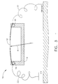
mirror element 12 is oriented at around 45 degrees with respect totransducer 24 axis. The transducer may be placed generally one inch or more above the mirror surface. In Fig. 4, the transducer-mirror apparatus curved surface 26 ofpart 28, a step-block. Theentry surface cone 30 resembles anellipse 30. The curvature ofmirror 12 is adjusted to shape the sound beam. - Fig. 4 shows the relative location and orientation of the mirror/transducer apparatus. The step block is an example of a "calibration block". This block has Flat Bottom Holes (FBHs) drilled at specific depths below the surface. Calibration is made off of these holes, then the production part is inspected to that sensitivity. The step block is the same shape (as to radius and acoustic properties) as a production part. It is used to develop/setup/measure an inspection.
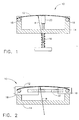
- Figs. 5, 6 and 7 illustrate a quick-coupler, detachable structure that can support both adjustable and nonadjustable (fixed) curvature mirrors. These drawings show how the interchangeable mirror element sits relative to the
transducer 24 and amanipulator head 34. In Fig. 5, a quick-coupler mirror collar 36 can use dowel pins to insure alignment. Thecollar 36 is aligned once during installation and is tightened around anUHF connector 38 associated withmanipulator head 34. - In Fig. 6, a quick-coupler,
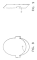
detachable mirror holder 40 can support themirror element 12, whether flat or curved, interchangeable or adjustable. It may be used in any ultrasonic inspection where a flat or curved 45-degree mirror is needed. Themirror holder 40 is preferably stainless steel or PVC. Guide slots (not shown) in the holder can be fitted to dowel pins on thecollar 36. As illustrated in Fig. 7, the beam focal properties, indicated bylines 42, are affected by the mirror element curvature. - Representative fixed mirror element examples are illustrated in Figs. 8 and 9. Fig. 8 illustrates a top view of the fixed
mirror element 12, and Fig. 9 illustrates a side view. Theinterchangeable mirror elements 12 can be flat or curved. Curved mirror elements will change the beam focal properties. - While the invention has been described with reference to a preferred embodiment, the process can be applied in various environments such as turbine blades with laser drilled holes. The process can also be applied to any part that has laser expulsion on its surface and around the hole.
- For completeness, various aspects of the invention are set out in the following numbered clauses:-
- 1. A method for improving ultrasonic inspection through a curved surface
(26), comprising the steps of:
- providing a mirror element (12) for shaping a sound beam of the ultrasonic inspection; and
- adjusting curvature of the mirror element (12) relative to the curved surface (26).
- 2. A method as claimed in clause 1 wherein the mirror element (12) comprises a single adjustable acoustic mirror.
- 3. A method as claimed in clause 2 wherein the step of adjusting curvature of the mirror element (12) comprises the step of changing the curvature of the adjustable acoustic mirror.
- 4. A method as claimed in clause 3 wherein the step of changing the curvature comprises the step of using a screw (16).
- 5. A method as claimed in clause 3 wherein the step of changing the curvature comprises the step of using at least one rod (32).
- 6. A method as claimed in clause 1 wherein the mirror element comprises a piezoelectric mirror (12).
- 7. A method as claimed in clause 6 wherein the step of adjusting curvature of the mirror element (12) comprises the step of using a voltage modulator.
- 8. A method as claimed in clause 1 wherein the mirror element (12) comprises multiple interchangeable mirrors, each having a fixed curvature on at least one side.
- 9. A method as claimed in clause 8 wherein the multiple interchangeable mirror elements (12) are each changed and locked in place by sliding over a spring-loaded tensioner (36).
- 10. A method as claimed in clause 8 wherein each multiple interchangeable mirror element (12) is locked in place by mechanical means.
- 11. A method as claimed in clause 8 wherein each multiple interchangeable mirror element (12) is used with a transducer (24) to create a transducer-mirror assembly (12, 24).
- 12. A method as claimed in clause 11 wherein the transducer-mirror assembly (12, 24) is detached and reattached to a manipulator head (34) by a cylindrical interconnect (38).
- 13. A method as claimed in clause 11 wherein the transducer-mirror assembly (12, 24) is detached and reattached to the manipulator head (34) by mechanical means.
- 14. A method system as claimed in clause 11 wherein at least part of the transducer-mirror assembly (12, 24) comprises lightweight plastic.
- 15. A method as claimed in clause 11 wherein each of the multiple interchangeable mirror elements (12) are detachable and attachable using mechanical means (36) which provides precise, repeatable positioning.
- 16. A method as claimed in clause 11 wherein the transducer (24) comprises a transducer having a spherically focused lens.
- 17. A method as claimed in clause 11 wherein the transducer (24) comprises a transducer having a flat lens.
- 18. A method for improving ultrasonic inspection through a curved surface
(26), comprising the steps of:
- providing a single acoustic adjustable mirror element (12) for shaping a sound beam of the ultrasonic inspection; and
- adjusting curvature of the mirror element (12) relative to the curved surface (26).
- 19. A method for improving ultrasonic inspection through a curved surface
(26), comprising the steps of:
- providing a plurality of curved mirror elements (12) for shaping a sound beam of the ultrasonic inspection; and
- interchanging the plurality of curved mirror elements (12) to adjust curvature of the mirror element (12) relative to the curved surface (26).
-
Claims (10)
- A method for improving ultrasonic inspection through a curved surface (26), comprising the steps of:providing a mirror element (12) for shaping a sound beam of the ultrasonic inspection; andadjusting curvature of the mirror element (12) relative to the curved surface (26).
- A method as claimed in claim 1 wherein the mirror element (12) comprises a single adjustable acoustic mirror.
- A method as claimed in claim 2 wherein the step of adjusting curvature of the mirror element (12) comprises the step of changing the curvature of the adjustable acoustic mirror.
- A method as claimed in claim 1 wherein the mirror element comprises a piezoelectric mirror (12).
- A method as claimed in claim 4 wherein the step of adjusting curvature of the mirror element (12) comprises the step of using a voltage modulator.
- A method as claimed in claim 1 wherein the mirror element (12) comprises multiple interchangeable mirrors, each having a fixed curvature on at least one side.
- A method as claimed in claim 6 wherein each multiple interchangeable mirror element (12) is used with a transducer (24) to create a transducer-mirror assembly (12, 24).
- A method as claimed in claim 7 wherein the transducer-mirror assembly (12, 24) is detached and reattached to the manipulator head (34) by mechanical means.
- A method as claimed in claim 7 wherein each of the multiple interchangeable mirror elements (12) are detachable and attachable using mechanical means (36) which provides precise, repeatable positioning.
- A method for improving ultrasonic inspection through a curved surface (26), comprising the steps of:providing a plurality of curved mirror elements (12) for shaping a sound beam of the ultrasonic inspection; andinterchanging the plurality of curved mirror elements (12) to adjust curvature of the mirror element (12) relative to the curved surface (26).
Applications Claiming Priority (2)
| Application Number | Priority Date | Filing Date | Title |
|---|---|---|---|
| US09/377,416 US6253619B1 (en) | 1999-08-20 | 1999-08-20 | Adjustable acoustic mirror |
| US377416 | 1999-08-20 |
Publications (3)
| Publication Number | Publication Date |
|---|---|
| EP1079369A2 true EP1079369A2 (en) | 2001-02-28 |
| EP1079369A3 EP1079369A3 (en) | 2004-03-17 |
| EP1079369B1 EP1079369B1 (en) | 2012-04-11 |
Family
ID=23489020
Family Applications (1)
| Application Number | Title | Priority Date | Filing Date |
|---|---|---|---|
| EP00306992A Expired - Lifetime EP1079369B1 (en) | 1999-08-20 | 2000-08-16 | Adjustable acoustic mirror |
Country Status (3)
| Country | Link |
|---|---|
| US (1) | US6253619B1 (en) |
| EP (1) | EP1079369B1 (en) |
| JP (1) | JP4761611B2 (en) |
Cited By (2)
| Publication number | Priority date | Publication date | Assignee | Title |
|---|---|---|---|---|
| GB2385126A (en) * | 2002-02-12 | 2003-08-13 | James Michael Boaden | Ultrasonic inspection using prism mirrors |
| EP2891525A1 (en) * | 2014-01-07 | 2015-07-08 | Samsung Medison Co., Ltd. | Ultrasonic probe |
Families Citing this family (6)
| Publication number | Priority date | Publication date | Assignee | Title |
|---|---|---|---|---|
| US6419156B1 (en) * | 1999-11-23 | 2002-07-16 | Telxon Corporation | Piezoelectric scan engine in PC card format |
| US7721607B2 (en) | 2006-11-30 | 2010-05-25 | General Electric Company | Ultrasonic inspection system, method, and apparatus |
| US8647281B2 (en) * | 2009-03-31 | 2014-02-11 | Boston Scientific Scimed, Inc. | Systems and methods for making and using an imaging core of an intravascular ultrasound imaging system |
| CA2762642C (en) | 2009-05-20 | 2018-07-10 | Imagenex Technology Corp. | Controlling an image element in a reflected energy measurement system |
| US20120059241A1 (en) * | 2010-09-08 | 2012-03-08 | Boston Scientific Scimed, Inc. | Systems and methods for making and using a steerable imaging system configured and arranged for insertion into a patient |
| FR2994046B1 (en) * | 2012-07-27 | 2017-05-19 | Jean Noel Duchamp | PAVILION SOUNDING DEVICE AND CONFLECTIVE REFLECTOR |
Citations (2)
| Publication number | Priority date | Publication date | Assignee | Title |
|---|---|---|---|---|
| JPH0397453A (en) | 1989-09-11 | 1991-04-23 | Olympus Optical Co Ltd | Ultrasonic diagnosing apparatus |
| WO1997009614A1 (en) | 1995-09-08 | 1997-03-13 | Framatome | Non destructive control device for the ultrasound controlling of an elongate part |
Family Cites Families (18)
| Publication number | Priority date | Publication date | Assignee | Title |
|---|---|---|---|---|
| US3622790A (en) * | 1969-05-01 | 1971-11-23 | Continental Oil Co | Method and apparatus for modulating coherent electromagnetic radiation |
| US3927557A (en) * | 1974-05-30 | 1975-12-23 | Gen Electric | Acoustic imaging apparatus with liquid-filled acoustic corrector lens |
| JPS5419797A (en) * | 1977-07-14 | 1979-02-14 | Mitsubishi Heavy Ind Ltd | Flaw locator of fariable focal point type |
| US4269067A (en) * | 1979-05-18 | 1981-05-26 | International Business Machines Corporation | Method and apparatus for focusing elastic waves converted from thermal energy |
| SU978952A1 (en) * | 1981-03-10 | 1982-12-07 | Ордена Трудового Красного Знамени Институт Сверхтвердых Материалов Ан Усср | Apparatus for focusing ultrasonic oscillations |
| JPS5817361A (en) * | 1981-07-24 | 1983-02-01 | Aloka Co Ltd | Ultrasonic probe |
| US4606031A (en) * | 1984-07-17 | 1986-08-12 | The United States Of America As Represented By The United States Department Of Energy | Device for frequency modulation of a laser output spectrum |
| JPS61209356A (en) * | 1985-03-13 | 1986-09-17 | Sumitomo Metal Ind Ltd | Ultrasonic flaw detection of round billet material |
| JPH0714884Y2 (en) * | 1989-08-14 | 1995-04-10 | 日本鋼管株式会社 | Ultrasonic probe holder for steel pipe |
| DE4037160A1 (en) * | 1990-11-22 | 1992-05-27 | Dornier Medizintechnik | ACOUSTIC FOCUSING DEVICE |
| JPH04218144A (en) * | 1990-12-18 | 1992-08-07 | Fujitsu Ltd | Ultrasonic probe |
| US5859417A (en) * | 1991-06-14 | 1999-01-12 | Symbol Technologies, Inc. | Optical scanners having dual surface optical elements for dual working ranges |
| JPH05134688A (en) * | 1991-11-14 | 1993-05-28 | Fujita Corp | Sound varying equipment using acoustic lens |
| JPH07121890A (en) * | 1993-10-21 | 1995-05-12 | Nippondenso Co Ltd | Optical head |
| JPH07184898A (en) * | 1993-12-28 | 1995-07-25 | Olympus Optical Co Ltd | Ultrasonic probe |
| US5677491A (en) * | 1994-08-08 | 1997-10-14 | Diasonics Ultrasound, Inc. | Sparse two-dimensional transducer array |
| JP3205678B2 (en) * | 1995-03-07 | 2001-09-04 | 日立電線株式会社 | Ultrasonic flaw detector for lead sheath tube |
| US5680863A (en) * | 1996-05-30 | 1997-10-28 | Acuson Corporation | Flexible ultrasonic transducers and related systems |
-
1999
- 1999-08-20 US US09/377,416 patent/US6253619B1/en not_active Expired - Lifetime
-
2000
- 2000-08-14 JP JP2000245474A patent/JP4761611B2/en not_active Expired - Lifetime
- 2000-08-16 EP EP00306992A patent/EP1079369B1/en not_active Expired - Lifetime
Patent Citations (2)
| Publication number | Priority date | Publication date | Assignee | Title |
|---|---|---|---|---|
| JPH0397453A (en) | 1989-09-11 | 1991-04-23 | Olympus Optical Co Ltd | Ultrasonic diagnosing apparatus |
| WO1997009614A1 (en) | 1995-09-08 | 1997-03-13 | Framatome | Non destructive control device for the ultrasound controlling of an elongate part |
Cited By (3)
| Publication number | Priority date | Publication date | Assignee | Title |
|---|---|---|---|---|
| GB2385126A (en) * | 2002-02-12 | 2003-08-13 | James Michael Boaden | Ultrasonic inspection using prism mirrors |
| EP2891525A1 (en) * | 2014-01-07 | 2015-07-08 | Samsung Medison Co., Ltd. | Ultrasonic probe |
| US10123774B2 (en) | 2014-01-07 | 2018-11-13 | Samsung Medison Co., Ltd. | Ultrasonic probe |
Also Published As
| Publication number | Publication date |
|---|---|
| JP2001074701A (en) | 2001-03-23 |
| JP4761611B2 (en) | 2011-08-31 |
| EP1079369A3 (en) | 2004-03-17 |
| EP1079369B1 (en) | 2012-04-11 |
| US6253619B1 (en) | 2001-07-03 |
Similar Documents
| Publication | Publication Date | Title |
|---|---|---|
| US5090798A (en) | Applied intensity distribution controlling apparatus | |
| US6253619B1 (en) | Adjustable acoustic mirror | |
| KR102040148B1 (en) | Fiber scanning optical probe and medical imaging apparatus employoing the same | |
| EP0487871B1 (en) | Ultrasonic micro spectrometer | |
| US5099693A (en) | Apparatus for investigating a sample with ultrasound | |
| DE3006895C2 (en) | Method and device for coupling or decoupling optical radiation | |
| US7721607B2 (en) | Ultrasonic inspection system, method, and apparatus | |
| US4445380A (en) | Selectable focus sphericone transducer and imaging apparatus | |
| KR100402385B1 (en) | testing head | |
| JPH04218766A (en) | Apparatus and method for ultrasonic beam sighting for nondestructive test | |
| US5381695A (en) | Apparatus for investigating a sample with ultrasound | |
| JPS59160754A (en) | Scan type acoustic microscope | |
| US4659175A (en) | Fiber waveguide coupling device | |
| US4621531A (en) | Ultrasonic microscope | |
| GB2202647A (en) | Laser beam focussing | |
| US4597293A (en) | Scanning acoustic microscope | |
| US10281707B2 (en) | Solid immersion lens holder for high resolution optical microscope | |
| JPH06208990A (en) | Method and apparatus for making laser beam perpendicular to reflection surface | |
| US4423637A (en) | Ultrasonic testing instrument and method | |
| CN210109043U (en) | Auxiliary device is adjusted to phased array instrument | |
| EP0000259A1 (en) | Process and apparatus for the alignment of a transducer forming part of a radiation generator | |
| EP0721577B1 (en) | Device for examining optical waveguides | |
| GB2249641A (en) | Tiltable deformable mirror | |
| JPH06250073A (en) | Position adjusting and fitting mechanism for mirror | |
| JPH01293853A (en) | Ultrasonic probe |
Legal Events
| Date | Code | Title | Description |
|---|---|---|---|
| PUAI | Public reference made under article 153(3) epc to a published international application that has entered the european phase |
Free format text: ORIGINAL CODE: 0009012 |
|
| AK | Designated contracting states |
Kind code of ref document: A2 Designated state(s): AT BE CH CY DE DK ES FI FR GB GR IE IT LI LU MC NL PT SE |
|
| AX | Request for extension of the european patent |
Free format text: AL;LT;LV;MK;RO;SI |
|
| PUAL | Search report despatched |
Free format text: ORIGINAL CODE: 0009013 |
|
| AK | Designated contracting states |
Kind code of ref document: A3 Designated state(s): AT BE CH CY DE DK ES FI FR GB GR IE IT LI LU MC NL PT SE |
|
| AX | Request for extension of the european patent |
Extension state: AL LT LV MK RO SI |
|
| RIC1 | Information provided on ipc code assigned before grant |
Ipc: 7G 10K 11/20 A Ipc: 7G 10K 11/28 B |
|
| 17P | Request for examination filed |
Effective date: 20040917 |
|
| AKX | Designation fees paid |
Designated state(s): DE FR IT |
|
| 17Q | First examination report despatched |
Effective date: 20080618 |
|
| REG | Reference to a national code |
Ref country code: DE Ref legal event code: R079 Ref document number: 60047066 Country of ref document: DE Free format text: PREVIOUS MAIN CLASS: G10K0011200000 Ipc: G01N0029220000 |
|
| RIC1 | Information provided on ipc code assigned before grant |
Ipc: G10K 11/20 20060101ALI20110908BHEP Ipc: G01N 29/22 20060101AFI20110908BHEP |
|
| GRAP | Despatch of communication of intention to grant a patent |
Free format text: ORIGINAL CODE: EPIDOSNIGR1 |
|
| GRAS | Grant fee paid |
Free format text: ORIGINAL CODE: EPIDOSNIGR3 |
|
| GRAA | (expected) grant |
Free format text: ORIGINAL CODE: 0009210 |
|
| AK | Designated contracting states |
Kind code of ref document: B1 Designated state(s): DE FR IT |
|
| REG | Reference to a national code |
Ref country code: DE Ref legal event code: R096 Ref document number: 60047066 Country of ref document: DE Effective date: 20120531 |
|
| PLBE | No opposition filed within time limit |
Free format text: ORIGINAL CODE: 0009261 |
|
| STAA | Information on the status of an ep patent application or granted ep patent |
Free format text: STATUS: NO OPPOSITION FILED WITHIN TIME LIMIT |
|
| 26N | No opposition filed |
Effective date: 20130114 |
|
| REG | Reference to a national code |
Ref country code: DE Ref legal event code: R097 Ref document number: 60047066 Country of ref document: DE Effective date: 20130114 |
|
| REG | Reference to a national code |
Ref country code: FR Ref legal event code: PLFP Year of fee payment: 17 |
|
| PGFP | Annual fee paid to national office [announced via postgrant information from national office to epo] |
Ref country code: DE Payment date: 20160826 Year of fee payment: 17 Ref country code: IT Payment date: 20160824 Year of fee payment: 17 |
|
| PGFP | Annual fee paid to national office [announced via postgrant information from national office to epo] |
Ref country code: FR Payment date: 20160825 Year of fee payment: 17 |
|
| REG | Reference to a national code |
Ref country code: DE Ref legal event code: R119 Ref document number: 60047066 Country of ref document: DE |
|
| REG | Reference to a national code |
Ref country code: FR Ref legal event code: ST Effective date: 20180430 |
|
| PG25 | Lapsed in a contracting state [announced via postgrant information from national office to epo] |
Ref country code: DE Free format text: LAPSE BECAUSE OF NON-PAYMENT OF DUE FEES Effective date: 20180301 |
|
| PG25 | Lapsed in a contracting state [announced via postgrant information from national office to epo] |
Ref country code: IT Free format text: LAPSE BECAUSE OF NON-PAYMENT OF DUE FEES Effective date: 20170816 Ref country code: FR Free format text: LAPSE BECAUSE OF NON-PAYMENT OF DUE FEES Effective date: 20170831 |