EP1079222A2 - Procedure and device for compensating unbalance by removing material - Google Patents
Procedure and device for compensating unbalance by removing material Download PDFInfo
- Publication number
- EP1079222A2 EP1079222A2 EP00117790A EP00117790A EP1079222A2 EP 1079222 A2 EP1079222 A2 EP 1079222A2 EP 00117790 A EP00117790 A EP 00117790A EP 00117790 A EP00117790 A EP 00117790A EP 1079222 A2 EP1079222 A2 EP 1079222A2
- Authority
- EP
- European Patent Office
- Prior art keywords
- rotor
- tools
- compensation
- compensating
- unbalance
- Prior art date
- Legal status (The legal status is an assumption and is not a legal conclusion. Google has not performed a legal analysis and makes no representation as to the accuracy of the status listed.)
- Granted
Links
Images
Classifications
-
- G—PHYSICS
- G01—MEASURING; TESTING
- G01M—TESTING STATIC OR DYNAMIC BALANCE OF MACHINES OR STRUCTURES; TESTING OF STRUCTURES OR APPARATUS, NOT OTHERWISE PROVIDED FOR
- G01M1/00—Testing static or dynamic balance of machines or structures
- G01M1/30—Compensating unbalance
- G01M1/34—Compensating unbalance by removing material from the body to be tested, e.g. from the tread of tyres
Definitions
- the invention relates to a method of compensation a determined unbalance on a rotor according to the generic term of claim 1 and a device for this purpose according to Preamble of claim 7.
- the Imbalance is generally related to one or more compensation levels and determined by size and angular position; with that is polar imbalance compensation possible. Can the unbalance compensation on rotors only at certain points along the circumference be carried out, the compensation will be carried out on suitable ones Locations carried out in components of the compensation vector.
- Anchoring electrical machines these are the pole pieces that over Bridges are connected to the anchor core, between which the Copper wire windings are arranged. The pole pieces should weakened as little as possible and especially milling through or avoiding grinding down to the windings become; furthermore, the component compensation should be carried out at the suitable Jobs are done in one operation.
- a method and a device of the type mentioned at the beginning are known from DE 42 29 521 A1.
- Here is the component balance made on an electrical anchor in one operation.
- three on one Tool spindle mounted compensating tools used that In order to remove material linearly in the axial direction of the tool spindle positioned tangentially to the rotor depending on the unbalance as well as moved in the radial direction for engagement in the rotor become.
- the rotor is used in this known method turned so far that the pole piece with the largest balancing mass is to be removed with its center axis on the middle of the three balancing tools.
- the compensation tools Before performing of the compensation process become the compensation tools with the tool spindle tangential to one determined by the compensated unbalance shifted certain way.
- the rotor is the leveling tools by stepless turning tracked its axis by a calculated angle that corresponds to the Displacement and the direction of movement of the middle compensation tool corresponds. Then, to compensate for unbalance the compensation tools by a linear path radial to the rotor moved so that the compensation tools with a calculated Penetrate the material.
- the process is considered to be disadvantageous in that the rotor Twisting around its axis of displacement of the compensation tools must be tracked.
- the object of the invention is therefore a method and Device of the type mentioned to compensate for a to create determined unbalance, with the simplest possible Setup of an exact unbalance compensation in one work step is feasible.
- the invention has the advantage that the rotor can be adjusted by Rotation of the rotor about its axis is not necessary, so that the structure of the device and the implementation of the Simplify the procedure considerably.
- the rotor armature remains as component compensation in two processing steps in a divisional position. This is particularly advantageous if the unbalance measurement and the unbalance compensation on different Machines or in different stations of a plant be carried out because the rotor only in one of its divisional Positions are and is a continuous one Screwing into machining positions is not necessary; a Screwing device for this can be omitted.
- the angular position setting the balance imbalance is according to the invention only two compensation tools made, so that an intermediate third compensation tool is not required for this is and at most to influence the amount of Compensation unbalance can be provided. It turned out to be special advantageously pointed out that the angular position adjustment over a large divisional angle range with small tangential displacement of the compensating tool set can be achieved. Through the oblique immersion of the compensation tools there is a larger slot length and thus better utilization of the pole shoe material available. In addition, if the pole piece is not machined between the compensating tools if necessary second compensation step possible. The release of this pole piece advantageously opens up the possibility of Support the rotor on at least this pole piece or Use of this pole piece for proper alignment of the rotor in the locking positions specified by the number of pole shoes.
- the Compensation tools approximately in the middle of the compensation points into the rotor, with the maximum immersion depth Machining profile is centered on the web axis and so and through the oblique immersion at, for example, 45 ° the one in question Compensation point, e.g. a pole piece of an electrical anchor, if possible is weakened little.
- a broad embodiment provides that with the balancing components in a one balancing point division corresponding angular range, which is on both sides of a possible compensation office or on both sides a middle level between two possible compensation points extends, lying imbalance vector is compensated. Either with an even as well as with an odd number of intermediate ones possible compensation points is always only a proper one Rotation of the rotor around a locking point required if the unbalance vector to be compensated is adjacent to specified angular range.
- the invention can be straight and odd number of compensation points of the rotor come.
- armature of an electric machine is shown schematically as rotor 1 represented in section by a compensation plane.
- the invention can be used with any rotor that Places equidistantly arranged along a rotor circumference for Balancing due to material removal, e.g. profiled Shafts or rotors with radial extensions such as blades or wings; the invention is also applicable to Rotors with smooth peripheral surfaces in the compensation level or levels.
- the anchor has twelve pole pieces 2, which over Bridges 3 are connected to the anchor core. In the fields of between the pole pieces 2 and the webs 3 they are not copper wire windings of the armature shown.
- the Pole shoes 2 are the possible compensation points of the rotor.
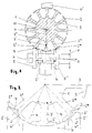
- the Rotor 1 has an unbalance U to be compensated, which is in the central plane of the lower web 3 'in the drawing between the anchor core and pole piece 2 'lies and points downward.
- U unbalance
- the Bracket has two holding elements 4, 4 ', of which the lower holding element 4 the rotor 1 in one by the division of 12 holds defined stop position. Fixing the rotor in a rest position as well as its support instead done by facilities that are on balancing machines anyway available.
- the unbalance compensation takes place via material distances on the pole shoes 2 ' ' and 2 ' ' , which are arranged to the left and right of the pole piece 2 'in the drawing.
- two pole pieces can also be selected, which are separated by two or more pole pieces in between.
- the compensating tools 5, 5 ' can be, for example, disk cutters or grinding wheels which rotate about the spindle axis for material removal, for example by means of the driven tool spindle 6.
- the axial distance between the compensating tools 5, 5' is essentially determined by the center distance of the pole shoes 2 'selected for compensation. , 2 ' ' 1, this is the distance A.
- the machining profile should then be centered on the web axis at maximum immersion depth.
- the compensating tools each have the tip of an essentially triangular machining profile 7, 7 ', which is also selected with regard to the shape of the pole shoe, taking into account the web transition.
- the tip can also be flattened to remove as much material as possible near the surface.
- the triangular shape is chosen so that the central plane of the web cuts the angle at the machining triangle tip approximately in half, since a maximum radial machining depth can be achieved by the machining profile 7, 7 'tapering in the radial direction.
- the angle at the triangle tip is preferably in the range between 90 ° and 120 °, depending on the selection and design of the pole piece and the web transition. With the selected processing profile, as much material as possible should be removable near the surface.
- the tool spindle 6 is below in the example shown the rotor 1 attached with horizontal orientation; it can however, if necessary, the entire device for balancing any angle, e.g. pivoted by 90 ° about the rotor axis 10 to be ordered.
- the tool spindle 6 is in at least two Steplessly shiftable directions, namely tangential in direction H. to the rotor 1 and transverse to the rotor axis 10 and thus in the Horizontal and in the direction V, namely radial and thus in the vertical.
- the drive for moving the tool spindle 6 can be electrical, hydraulically or by other known drive mechanisms respectively.
- the Rotor 1 are moved; it can also be provided that Carry out tool spindle 6 and rotor 1 displacement movements.
- the tool spindle 6 is not displaced in the horizontal or tangential direction and is therefore in the symmetrical position shown with the tips of the compensation tools 5 ', 5' 'in each case at a distance A / 2 from the Middle plane of the web 3 '.
- the penetration depth of the compensating tools 5 ', 5' ' is determined by an evaluation device (not shown) on the basis of the unbalance U to be compensated and the specific conditions of the rotor 1 and machining profile of the compensating tools 5', 5 ' ' and the tool spindle 6 by the corresponding path in the vertical direction V shifted for material removal.
- the compensating tools 5 and 5 ' are indicated in three different positions; the unbroken lines show the axial and radial position of the compensation tools 5 and 5 ', with which an imbalance running in the center of the web 3' is compensated.
- An unbalance which runs in the direction of the dashed line a can be compensated for with the compensating tools 5, 5 'in the axially and radially displaced position a', a '' , in which the compensating tool 5 on the pole piece 2 '' of the web 3 '' when moving to a ', more material is removed than the compensating tool 5' when moving to position a '' on pole piece 2 '' ' .
- An unbalance that runs in the direction of the narrow dashed line b can be compensated for with the compensating tools 5, 5 'in the axially and radially displaced position b ' , b '' .
- both compensating tools 5, 5' are in engagement.
- the tip of the machining profile 7, 7 'of the deeper-penetrating compensation tool 5 or 5' lies at the maximum penetration depth in the central plane of the web 3 '' , 3 '''concerned .
- the angle at the tip of the machining profile 7, 7 ' is approximately 120 ° in the example shown and can be selected up to approximately 160 ° if necessary, and is therefore greater than the angle of the machining tip selected in the case of the 12-pitch rotor according to FIG. 1 of about 90 °.
- the angular range at the tip of the machining profile 7, 7 ' extends approximately symmetrically to the central plane of the web 3 '' , 3 ''' .
- the maximum tangential displacement of the compensation tools 5, 5 'in the position a ' , a ' or the position b ' , b ' corresponds to about 1/4 of the maximum penetration depth in the web direction in the example shown
- FIG. 1 An embodiment is not shown, in which a Rotor with 12 division, as shown in Fig. 1, instead only one pole piece two pole pieces between the pole pieces which are to be compensated.
- the rotor is in a position in which the central plane between two pole pieces facing downwards, fixable according to division.
- a divisional Angular range in which the unbalance to be compensated can lie, reached, i.e. in the case of a rotor with 12 compensation points an angular range of 30 ° between two adjacent webs.
- the invention also extends to arrangements in which the material decreases at immediately adjacent compensation points is made; however, in this case there is an unbalance compensation area given by a division only if one of the two compensation tools when hiking the determined Unbalance in an unbalance limit position in the central plane of a Stegs does the material removal alone while the other Compensation tool for this case of unbalance in the unbalance limit position in the middle plane not to interfere with the other Compensation point comes.
Abstract
Description
Die Erfindung bezieht sich auf ein Verfahren zum Ausgleich
einer ermittelten Unwucht an einem Rotor nach dem Oberbegriff
des Patentanspruchs 1 und eine Vorrichtung hierzu nach dem
Oberbegriff des Patentanspruchs 7.The invention relates to a method of compensation
a determined unbalance on a rotor according to the generic term
of claim 1 and a device for this purpose according to
Preamble of
Beim Auswuchten von Rotoren wird zunächst deren Unwucht in einer Unwuchtmeßmaschine bzw. Auswuchtmaschine ermittelt. Die Unwucht wird im allgemeinen bezogen auf eine oder mehrere Ausgleichsebenen und nach Größe und Winkellage bestimmt; damit ist ein polarer Unwuchtausgleich möglich. Kann der Unwuchtausgleich an Rotoren nur an bestimmten längs des Umfangs verteilten Stellen durchgeführt werden, wird der Ausgleich an dafür geeigneten Stellen in Komponenten des Ausgleichsvektors durchgeführt. Bei Ankern von Elektromaschinen sind dies die Polschuhe, die über Stege mit dem Ankerkern verbunden sind, zwischen denen die Kupferdrahtwicklungen angeordnet sind. Dabei sollen die Polschuhe möglichst wenig geschwächt und insbesondere ein Durchfräsen oder Schleifen bis auf die Wicklungen sicher vermieden werden; ferner soll der Komponentenausgleich an den dafür geeigneten Stellen in einem Arbeitsgang erfolgen.When balancing rotors, their unbalance is first checked in an unbalance measuring machine or balancing machine. The Imbalance is generally related to one or more compensation levels and determined by size and angular position; with that is polar imbalance compensation possible. Can the unbalance compensation on rotors only at certain points along the circumference be carried out, the compensation will be carried out on suitable ones Locations carried out in components of the compensation vector. At Anchoring electrical machines, these are the pole pieces that over Bridges are connected to the anchor core, between which the Copper wire windings are arranged. The pole pieces should weakened as little as possible and especially milling through or avoiding grinding down to the windings become; furthermore, the component compensation should be carried out at the suitable Jobs are done in one operation.
Ein Verfahren und eine Vorrichtung der eingangs genannten Art sind aus der DE 42 29 521 A1 bekannt. Hier wird der Komponentenausgleich an einem Elektroanker in einem Arbeitsgang vorgenommen. Bei diesem bekannten Verfahren werden drei auf einer Werkzeugspindel montierte Ausgleichswerkzeuge verwendet, die zwecks Materialabtrag linear sowohl in Achsrichtung der Werkzeugspindel tangential zum Rotor unwuchtabhängig positioniert als auch in radialer Richtung zum Eingriff in den Rotor verschoben werden. Der Rotor wird bei diesem bekannten Verfahren so weit gedreht, daß der Polschuh, bei dem die größte Ausgleichsmasse zu entfernen ist, mit seiner Mittenachse auf das mittlere der drei Ausgleichswerkzeuge gerichtet ist. Vor Durchführung des Ausgleichsvorgangs werden die Ausgleichswerkzeuge mit der Werkzeugspindel tangential um einen durch die ermittelte auszugleichende Unwucht bestimmten Weg verschoben. Der Rotor wird den Ausgleichswerkzeugen durch stufenloses Verdrehen um seine Achse um einen errechneten Winkel nachgeführt, der dem Verschiebeweg und der Verschieberichtung des mittleren Ausgleichswerkzeugs entspricht. Zum Unwuchtausgleich werden danach die Ausgleichswerkzeuge um einen linearen Weg radial zum Rotor verschoben, so daß die Ausgleichswerkzeuge mit einer errechneten Eindringtiefe den Materialabtrag vornehmen. Bei dem bekannten Verfahren ist als nachteilig anzusehen, daß der Rotor durch Verdrehen um seine Achse der Verschiebung der Ausgleichswerkzeuge nachgeführt werden muß.A method and a device of the type mentioned at the beginning are known from DE 42 29 521 A1. Here is the component balance made on an electrical anchor in one operation. In this known method, three on one Tool spindle mounted compensating tools used that In order to remove material linearly in the axial direction of the tool spindle positioned tangentially to the rotor depending on the unbalance as well as moved in the radial direction for engagement in the rotor become. The rotor is used in this known method turned so far that the pole piece with the largest balancing mass is to be removed with its center axis on the middle of the three balancing tools. Before performing of the compensation process become the compensation tools with the tool spindle tangential to one determined by the compensated unbalance shifted certain way. The rotor is the leveling tools by stepless turning tracked its axis by a calculated angle that corresponds to the Displacement and the direction of movement of the middle compensation tool corresponds. Then, to compensate for unbalance the compensation tools by a linear path radial to the rotor moved so that the compensation tools with a calculated Penetrate the material. With the well-known The process is considered to be disadvantageous in that the rotor Twisting around its axis of displacement of the compensation tools must be tracked.
Aufgabe der Erfindung ist es deshalb, ein Verfahren und eine Vorrichtung der eingangs genannten Art zum Ausgleich einer ermittelten Unwucht zu schaffen, bei der bei möglichst einfachem Aufbau ein genauer Unwuchtausgleich in einem Arbeitsgang durchführbar ist.The object of the invention is therefore a method and Device of the type mentioned to compensate for a to create determined unbalance, with the simplest possible Setup of an exact unbalance compensation in one work step is feasible.
Erfindungsgemäß wird diese Aufgabe durch die in den Patentansprüchen
1, 2 und 7, 8 angegebenen Merkmale gelöst. Die Erfindung
hat den Vorteil, daß die Nachführung des Rotors durch
Verdrehen des Rotors um seine Achse nicht erforderlich ist, so
daß sich der Aufbau der Vorrichtung und die Durchführung des
Verfahrens erheblich vereinfachen. Der Rotoranker bleibt wie
beim Komponentenausgleich in zwei Bearbeitungsschritten in
einer teilungsgemäßen Stellung. Dies ist besonders vorteilhaft,
wenn die Unwuchtmessung und der Unwuchtausgleich auf verschiedenen
Maschinen oder in verschiedenen Stationen einer Anlage
durchgeführt werden, da der Rotor nur in eine seiner teilungsgemäßen
Stellungen zu bringen ist und ein kontinuierliches
Eindrehen in Bearbeitungslagen nicht erforderlich ist; eine
Eindrehvorrichtung hierfür kann damit entfallen. Die Winkellageneinstellung
der Ausgleichsunwucht wird erfindungsgemäß über
nur zwei Ausgleichswerkzeuge vorgenommen, so daß auch ein zwischengeordnetes
drittes Ausgleichswerkzeug hierfür nicht erforderlich
ist und allenfalls zur Beeinflussung des Betrags der
Ausgleichsunwucht vorgesehen werden kann. Es hat sich als besonders
vorteilhaft herausgestellt, daß die Winkellageneinstellung
über einen großen teilungsgemäßen Winkelbereich mit kleinen
tangentialen Verschiebewegen des Ausgleichswerkzeugsatzes
erzielt werden kann. Durch das schräge Eintauchen der Ausgleichswerkzeuge
ergibt sich eine größere Schlitzlänge und
damit bessere Ausnutzung des zur Verfügung stehenden Polschuhmaterials.
Darüberhinaus ist bei Nichtbearbeitung des Polschuhs
zwischen den Ausgleichswerkzeugen bei Bedarf ohne weiteres ein
zweiter Ausgleichsschritt möglich. Das Freilassen dieses Polschuhs
eröffnet in vorteilhafter Weise die Möglichkeit der
Abstützung des Rotors an mindestens diesem Polschuh bzw. die
Heranziehung dieses Polschuhs zum teilungsgemäßen Ausrichten
des Rotors in den durch die Polschuhzahl vorgegebenen Raststellungen.According to the invention, this object is achieved by the in the
In einer vorteilhaften Weiterbildung der Erfindung tauchen die Ausgleichswerkzeuge etwa mittig bezüglich der Ausgleichsstellen in den Rotor ein, wobei dann bei maximaler Eintauchtiefe das Bearbeitungsprofil mittig zur Stegachse liegt und so und durch das schräge Eintauchen unter beispielsweise 45° die betreffende Ausgleichsstelle, z.B. ein Polschuh eines Elektroankers, möglichst wenig geschwächt wird.In an advantageous development of the invention, the Compensation tools approximately in the middle of the compensation points into the rotor, with the maximum immersion depth Machining profile is centered on the web axis and so and through the oblique immersion at, for example, 45 ° the one in question Compensation point, e.g. a pole piece of an electrical anchor, if possible is weakened little.
Erfindungsgemäß wird in einer weiten Ausgestaltung vorgesehen, daß mit den Ausgleichskomponenten ein in einem einer Ausgleichsstellenteilung entsprechenden Winkelbereich, der sich beiderseits einer möglichen Ausgleichsstelle oder beiderseits einer Mittelebene zwischen zwei möglichen Ausgleichsstellen erstreckt, liegender Unwuchtvektor ausgeglichen wird. Sowohl bei einer geraden als auch bei ungerader Anzahl von zwischengeordneten möglichen Ausgleichsstellen ist stets nur eine teilungsgemäße Verdrehung des Rotors um eine Raststelle erforderlich, wenn der auszugleichende Unwuchtvektor benachbart zum angegebenen Winkelbereich liegt. Die Erfindung kann bei gerader und ungerader Ausgleichsstellenzahl des Rotors zur Anwendung kommen.According to the invention, a broad embodiment provides that with the balancing components in a one balancing point division corresponding angular range, which is on both sides of a possible compensation office or on both sides a middle level between two possible compensation points extends, lying imbalance vector is compensated. Either with an even as well as with an odd number of intermediate ones possible compensation points is always only a proper one Rotation of the rotor around a locking point required if the unbalance vector to be compensated is adjacent to specified angular range. The invention can be straight and odd number of compensation points of the rotor come.
Weiterbildungen der Erfindung sind in den weiteren Unteransprüchen angegeben.Further developments of the invention are in the further subclaims specified.
Die Erfindung wird im folgenden anhand von in der Zeichnung dargestellten Ausführungsbeispielen näher erläutert. Es zeigen:
- Fig. 1
- eine schematische Darstellung einer Vorrichtung zum Unwuchtausgleich an einem 12-poligen Rotor, bei der die auszugleichende Unwucht U in der Stegachse eines Polschuhs verläuft,
- Fig. 2
- eine Schemadarstellung bei einem Rotor mit acht möglichen Ausgleichsstellen
- Fig. 1
- 1 shows a schematic representation of a device for balancing an unbalance on a 12-pole rotor, in which the unbalance U to be compensated runs in the web axis of a pole piece,
- Fig. 2
- a schematic representation of a rotor with eight possible compensation points
In Fig. 1 ist als Rotor 1 der Anker einer Elektromaschine schematisch
im Schnitt durch eine Ausgleichsebene dargestellt. Die
Erfindung kann jedoch bei jedem Rotor eingesetzt werden, der
längs eines Rotorumfangs äquidistant angeordnete Stellen zum
Unwuchtausgleich durch Materialabtrag aufweist, wie z.B. profilierte
Wellen oder Rotoren mit radialen Fortsätzen wie Schaufeln
oder Flügeln; die Erfindung ist aber auch anwendbar bei
Rotoren mit glatten Umfangsoberflächen in der oder den Ausgleichsebenen.
Der Anker weist zwölf Polschuhe 2 auf, die über
Stege 3 mit dem Ankerkern in Verbindung stehen. In den Bereichen
zwischen den Polschuhen 2 und den Stegen 3 sind die nicht
dargestellten Kupferdrahtwicklungen des Ankers angeordnet. Die
Polschuhe 2 sind die möglichen Ausgleichsstellen des Rotors.In Fig. 1, the armature of an electric machine is shown schematically as rotor 1
represented in section by a compensation plane. The
However, the invention can be used with any rotor that
Places equidistantly arranged along a rotor circumference for
Balancing due to material removal, e.g. profiled
Shafts or rotors with radial extensions such as blades
or wings; the invention is also applicable to
Rotors with smooth peripheral surfaces in the compensation level or levels.
The anchor has twelve
Im dargestellten Ausführungsbeispiel nach Fig. 1 weist der
Rotor 1 eine auszugleichende Unwucht U auf, die in der Mittelebene
des in der Zeichnung unteren Steges 3' zwischen Ankerkern
und Polschuh 2'liegt und nach unten weist. Zum Unwuchtausgleich
ist der Rotor 1 über den Polschuh 2' und den diametral gegenüberliegenden
Polschuh mittels einer Halterung fixiert. Die
Halterung weist zwei Halteelemente 4, 4' auf, von denen das
untere Halteelement 4 den Rotor 1 in einer durch die 12er-Teilung
definierten Raststellung hält. Die Fixierung des Rotors in
einer Raststellung kann ebenso wie seine Abstützung stattdessen
durch Einrichtungen erfolgen, die an Auswuchtmaschinen ohnehin
vorhanden sind. In the exemplary embodiment shown in FIG. 1, the
Rotor 1 has an unbalance U to be compensated, which is in the central plane
of the lower web 3 'in the drawing between the anchor core
and pole piece 2 'lies and points downward. For unbalance compensation
is the rotor 1 via the pole piece 2 'and the diametrically opposite one
Pole shoe fixed with a bracket. The
Bracket has two
Der Unwuchtausgleich erfolgt über Materialentfernungen an den
Polschuhen 2'' und 2'' ![]()
![]()
Zum Materialabtrag an den Polschuhen 2'' und 2''
Die Werkzeugspindel 6 ist im dargestellten Beispiel unterhalb
des Rotors 1 mit horizontaler Ausrichtung angebracht; es kann
jedoch bei Bedarf die ganze Vorrichtung zum Unwuchtausgleich um
beliebige Winkel, z.B. um 90°, um die Rotorachse 10 geschwenkt
angeordnet werden. Die Werkzeugspindel 6 ist in mindestens zwei
Richtungen stufenlos verschiebbar, nämlich in Richtung H tangential
zum Rotor 1 und quer zur Rotorachse 10 und damit in der
Horizontalen und in der Richtung V, nämlich radial und damit in
der Vertikalen.The tool spindle 6 is below in the example shown
the rotor 1 attached with horizontal orientation; it can
however, if necessary, the entire device for balancing
any angle, e.g. pivoted by 90 ° about the
Eine bedarfsweise vorgesehene Verschiebung in der dritten Koordinatenrichtung,
nämlich parallel zur Rotorachse 10, ermöglicht
die Entfernung weiteren Materials durch Erstreckung des Bearbeitungsschlitzes
parallel zur Rotorachse 10 zu beiden Seiten
der Ausgleichsebene.A shift in the third coordinate direction, if required,
namely parallel to the
Der Antrieb zur Verschiebung der Werkzeugspindel 6 kann elektrisch, hydraulisch oder durch andere bekannte Antriebsmechanismen erfolgen.The drive for moving the tool spindle 6 can be electrical, hydraulically or by other known drive mechanisms respectively.
Anstelle der Verschiebung der Werkzeugspindel 6 kann auch der Rotor 1 verschoben werden; es kann auch vorgesehen werden, daß Werkzeugspindel 6 und Rotor 1 Verschiebebewegungen durchführen.Instead of the displacement of the tool spindle 6, the Rotor 1 are moved; it can also be provided that Carry out tool spindle 6 and rotor 1 displacement movements.
Zum Ausgleich der in Fig. 1 dargestellten Unwucht U wird die Werkzeugspindel 6 in horizontaler bzw. tangentialer Richtung nicht verschoben und befindet sich somit in der dargestellten symmetrischen Lage mit den Spitzen der Ausgleichswerkzeuge 5', 5'' jeweils im Abstand A/2 von der Mittelebene des Stegs 3'. Die Eindringtiefe der Ausgleichswerkzeuge 5', 5'' wird durch eine nicht dargestellte Auswerteeinrichtung auf der Grundlage der auszugleichenden Unwucht U und der spezifischen Verhältnisse von Rotor 1 und Bearbeitungsprofil der Ausgleichswerkzeuge 5' , 5'' ermittelt und die Werkzeugspindel 6 um den entsprechenden Weg in der Vertikalrichtung V zur Materialentfernung verschoben.To compensate for the unbalance U shown in FIG. 1, the tool spindle 6 is not displaced in the horizontal or tangential direction and is therefore in the symmetrical position shown with the tips of the compensation tools 5 ', 5''in each case at a distance A / 2 from the Middle plane of the web 3 '. The penetration depth of the compensating tools 5 ', 5'' is determined by an evaluation device (not shown) on the basis of the unbalance U to be compensated and the specific conditions of the rotor 1 and machining profile of the compensating tools 5', 5 '' and the tool spindle 6 by the corresponding path in the vertical direction V shifted for material removal.
Die Situation bei einer nicht in der Mittelebene eines Stegs 3
verlaufenden Unwucht wird im folgenden anhand der Fig. 2 erläutert.
Dargestellt ist aus Gründen der Übersichtlichkeit ein
Rotor 1 mit acht Polschuhen 2, also mit einer Winkel- bzw.
Ausgleichsstellenteilung von 45°. Die ermittelte Unwucht kann
im dargestellten Beispiel in dem durch die beiden unterschiedlich
gestrichelten Linien a, b angegebenen Winkelbereich liegen,
wobei der Winkel α dieses Winkelbereichs einer Teilung
des Rotors 1 entspricht und damit 45° beträgt. Die Linien a und
b und damit der Winkelbereich liegen symmetrisch zur Mittel-ebene
des Stegs 3'. Liegt die Unwucht außerhalb dieses Winkelbereichs,
ist der Rotor 1 vor dem Ausgleich durch schrittweise
Drehung um eine oder mehrere Ausgleichsstellenteilungen in die
geeignete Raststellung zu überführen, in der dann die Unwucht
innerhalb des Winkelbereichs um die Mittelebene des dann nach
unten weisenden Rotorstegs liegt, an dessen Polschuh jedoch
selbst kein Ausgleich vorgenommen wird.The situation with a
In der Fig. 2 sind die Ausgleichswerkzeuge 5 und 5' in drei
verschiedenen Stellungen angedeutet; mit nicht unterbrochenen
Linien ist die axiale und radiale Stellung der Ausgleichswerkzeuge
5 und 5' dargestellt, mit der eine in der Stegmitte des
Stegs 3' verlaufende Unwucht ausgeglichen wird. Eine Unwucht,
die in Richtung der gestrichelten Linie a verläuft, ist mit den
Ausgleichswerkzeugen 5, 5' in der axial und radial verschobenen
Stellung a', a'' ausgleichbar, in der das Ausgleichswerkzeug 5
am Polschuh 2'' des Stegs 3'' bei Verschiebung nach a' mehr Material
entfernt als das Ausgleichswerkzeug 5' bei Verschiebung in
die Stellung a'' am Polschuh 2'''. Eine Unwucht, die in Richtung
der eng gestrichelten Linie b verläuft, ist mit den Ausgleichswerkzeugen
5, 5' in der axial und radial verschobenen Stellung
b', b'' ausgleichbar. In allen dargestellten Stellungen und
allen Zwischenstellungen der Ausgleichswerkzeuge 5, 5' sind
beide Ausgleichswerkzeuge 5, 5' in Eingriff. Die Spitze des
Bearbeitungsprofils 7, 7' des tiefer eindringenden Ausgleichswerkzeugs
5 oder 5' liegt bei maximaler Eindringtiefe in der
Mittelebene des betreffenden Steges 3'', 3'''. Der Winkel an der
Spitze des Bearbeitungsprofils 7, 7' liegt im dargestellten
Beispiel bei etwa 120° und kann bei Bedarf bis ca.160° gewählt
werden und ist damit größer als der bei dem Rotor mit 12er
Teilung nach Fig. 1 gewählte Winkel der Bearbeitungsspitze von
etwa 90°. Der Winkelbereich an der Spitze des Bearbeitungsprofils
7, 7' erstreckt sich in etwa symmetrisch zur Mittelebene
des Stegs 3'', 3'''. Die maximale tangentiale Verschiebung der
Ausgleichswerkzeuge 5, 5' in die Stellung a', a'
Nicht dargestellt ist eine Ausführungsform, bei der bei einem Rotor mit 12er Teilung, wie er in Fig. 1 dargestellt ist, statt nur eines Polschuhs zwei Polschuhe zwischen den Polschuhen, an denen der Ausgleich vorgenommen werden soll, angeordnet sind. Der Rotor ist dabei in einer Stellung, in der die Mittelebene zwischen zwei Polschuhen nach unten weist, teilungsgemäß fixierbar. Auch mit dieser Anordnung wird ein teilungsgemäßer Winkelbereich, in dem die auszugleichende Unwucht liegen kann, erreicht, d.h. im Fall eines Rotors mit 12 Ausgleichsstellen ein Winkelbereich von 30° zwischen zwei benachbarten Stegen.An embodiment is not shown, in which a Rotor with 12 division, as shown in Fig. 1, instead only one pole piece two pole pieces between the pole pieces which are to be compensated. The rotor is in a position in which the central plane between two pole pieces facing downwards, fixable according to division. With this arrangement, too, is a divisional Angular range in which the unbalance to be compensated can lie, reached, i.e. in the case of a rotor with 12 compensation points an angular range of 30 ° between two adjacent webs.
Die Erfindung erstreckt sich auch auf Anordnungen, bei denen die Materialabnabme an unmittelbar benachbarten Ausgleichsstellen vorgenommen wird; allerdings ist in diesem Falle ein Unwuchtausgleichsbereich von einer Teilung nur dann gegeben, wenn eines der beiden Ausgleichswerkzeuge bei Wandern der ermittelten Unwucht in eine Unwuchtgrenzlage in der Mittelebene eines Stegs den Materialabtrag alleine übernimmt, während das andere Ausgleichswerkzeug für diesen Fall der Unwucht in der Unwuchtgrenzlage in der Mittelebene nicht zum Eingriff an der anderen Ausgleichsstelle kommt.The invention also extends to arrangements in which the material decreases at immediately adjacent compensation points is made; however, in this case there is an unbalance compensation area given by a division only if one of the two compensation tools when hiking the determined Unbalance in an unbalance limit position in the central plane of a Stegs does the material removal alone while the other Compensation tool for this case of unbalance in the unbalance limit position in the middle plane not to interfere with the other Compensation point comes.
Claims (11)
Applications Claiming Priority (2)
| Application Number | Priority Date | Filing Date | Title |
|---|---|---|---|
| DE19940469 | 1999-08-26 | ||
| DE19940469A DE19940469A1 (en) | 1999-08-26 | 1999-08-26 | Method and device for unbalance compensation |
Publications (3)
| Publication Number | Publication Date |
|---|---|
| EP1079222A2 true EP1079222A2 (en) | 2001-02-28 |
| EP1079222A3 EP1079222A3 (en) | 2002-10-02 |
| EP1079222B1 EP1079222B1 (en) | 2010-05-12 |
Family
ID=7919665
Family Applications (1)
| Application Number | Title | Priority Date | Filing Date |
|---|---|---|---|
| EP00117790A Expired - Lifetime EP1079222B1 (en) | 1999-08-26 | 2000-08-18 | Procedure and device for compensating unbalance by removing material |
Country Status (4)
| Country | Link |
|---|---|
| US (1) | US6520012B1 (en) |
| EP (1) | EP1079222B1 (en) |
| JP (1) | JP2001108560A (en) |
| DE (2) | DE19940469A1 (en) |
Cited By (1)
| Publication number | Priority date | Publication date | Assignee | Title |
|---|---|---|---|---|
| EP2048769A1 (en) * | 2003-08-18 | 2009-04-15 | VORWERK & CO. INTERHOLDING GmbH | Reluctance Motor |
Families Citing this family (5)
| Publication number | Priority date | Publication date | Assignee | Title |
|---|---|---|---|---|
| US7534970B2 (en) * | 2006-06-15 | 2009-05-19 | Schenck Accurate, Inc. | Counterbalanced dispensing system |
| US8342804B2 (en) | 2008-09-30 | 2013-01-01 | Pratt & Whitney Canada Corp. | Rotor disc and method of balancing |
| US9151298B2 (en) * | 2009-10-29 | 2015-10-06 | Koninklijke Philips N.V. | System and method for balancing an impeller assembly |
| JP5737015B2 (en) * | 2011-07-06 | 2015-06-17 | 株式会社Ihi | Unbalance correction method for rotating body |
| DE102017125889A1 (en) * | 2017-11-06 | 2019-05-09 | Thyssenkrupp Ag | Method and device for balancing |
Citations (5)
| Publication number | Priority date | Publication date | Assignee | Title |
|---|---|---|---|---|
| GB1023670A (en) * | 1961-12-14 | 1966-03-23 | Avery Ltd W & T | A device for compensating unbalance in rotatable bodies |
| DE2638876A1 (en) * | 1976-08-28 | 1978-03-09 | Hofmann Gmbh & Co Kg Maschinen | Rotor balancing device of compact construction - uses axially and longitudinally movable double cutter unit |
| US4442712A (en) * | 1981-02-27 | 1984-04-17 | Gebr. Hofmann Gmbh & Co. Kg, Maschinenfabrik | Method and apparatus for correcting the unbalance present in a rotor |
| JPH05215634A (en) * | 1992-02-04 | 1993-08-24 | Mitsuba Electric Mfg Co Ltd | Device for correcting unbalance of rotor |
| DE4229521A1 (en) * | 1992-09-07 | 1994-03-10 | Schenck Ag Carl | Electric motor armature rotor balancing - using machine tools, movable tangentially and linearly to circumference of rotor, to remove material from symmetrically-distributed points around rotor |
Family Cites Families (6)
| Publication number | Priority date | Publication date | Assignee | Title |
|---|---|---|---|---|
| DE2243002B1 (en) * | 1972-09-01 | 1973-11-15 | Gebr. Hofmann Kg Maschinenfabrik, 6100 Darmstadt | Method and device for balancing rotors |
| DE2946581C2 (en) * | 1979-11-19 | 1982-06-16 | Gebr. Hofmann Gmbh & Co Kg Maschinenfabrik, 6100 Darmstadt | Method and circuit arrangement for eliminating imbalances on rotating bodies |
| DE3005423A1 (en) * | 1980-02-14 | 1981-08-20 | Dionys Hofmann GmbH, Maschinenfabrik, 7470 Albstadt | Balancing rotors, esp. electric motor armatures, - using separate static and dynamic measurement and correction processes |
| DE3638158A1 (en) * | 1986-11-08 | 1988-05-11 | Schenck Ag Carl | UNBALANCE MEASURING STATION |
| US5199992A (en) * | 1990-03-01 | 1993-04-06 | Hines Industries, Inc. | Apparatus for the single station balancing and correction of rotating workpieces |
| IT1285484B1 (en) * | 1996-10-08 | 1998-06-08 | Balance Systems Srl | DEVICE FOR BALANCING A ROTOR BY REMOVING MATERIAL |
-
1999
- 1999-08-26 DE DE19940469A patent/DE19940469A1/en not_active Withdrawn
-
2000
- 2000-08-18 EP EP00117790A patent/EP1079222B1/en not_active Expired - Lifetime
- 2000-08-18 DE DE50015924T patent/DE50015924D1/en not_active Expired - Lifetime
- 2000-08-21 US US09/642,368 patent/US6520012B1/en not_active Expired - Lifetime
- 2000-08-28 JP JP2000257785A patent/JP2001108560A/en active Pending
Patent Citations (5)
| Publication number | Priority date | Publication date | Assignee | Title |
|---|---|---|---|---|
| GB1023670A (en) * | 1961-12-14 | 1966-03-23 | Avery Ltd W & T | A device for compensating unbalance in rotatable bodies |
| DE2638876A1 (en) * | 1976-08-28 | 1978-03-09 | Hofmann Gmbh & Co Kg Maschinen | Rotor balancing device of compact construction - uses axially and longitudinally movable double cutter unit |
| US4442712A (en) * | 1981-02-27 | 1984-04-17 | Gebr. Hofmann Gmbh & Co. Kg, Maschinenfabrik | Method and apparatus for correcting the unbalance present in a rotor |
| JPH05215634A (en) * | 1992-02-04 | 1993-08-24 | Mitsuba Electric Mfg Co Ltd | Device for correcting unbalance of rotor |
| DE4229521A1 (en) * | 1992-09-07 | 1994-03-10 | Schenck Ag Carl | Electric motor armature rotor balancing - using machine tools, movable tangentially and linearly to circumference of rotor, to remove material from symmetrically-distributed points around rotor |
Non-Patent Citations (1)
| Title |
|---|
| PATENT ABSTRACTS OF JAPAN vol. 017, no. 654 (P-1653), 3. Dezember 1993 (1993-12-03) & JP 05 215634 A (MITSUBA ELECTRIC MFG CO LTD), 24. August 1993 (1993-08-24) * |
Cited By (1)
| Publication number | Priority date | Publication date | Assignee | Title |
|---|---|---|---|---|
| EP2048769A1 (en) * | 2003-08-18 | 2009-04-15 | VORWERK & CO. INTERHOLDING GmbH | Reluctance Motor |
Also Published As
| Publication number | Publication date |
|---|---|
| JP2001108560A (en) | 2001-04-20 |
| DE19940469A1 (en) | 2001-03-01 |
| EP1079222B1 (en) | 2010-05-12 |
| US6520012B1 (en) | 2003-02-18 |
| EP1079222A3 (en) | 2002-10-02 |
| DE50015924D1 (en) | 2010-06-24 |
Similar Documents
| Publication | Publication Date | Title |
|---|---|---|
| DE2442139C2 (en) | ||
| WO2015071294A1 (en) | Honing tool and method for machining a plurality of coaxial bores | |
| DE2165497A1 (en) | MACHINE FOR AUTOMATIC, FAST AND ACCURATE MACHINING OF SMALL PARTS, EVEN COMPLEX SHAPING | |
| DE19821763B4 (en) | Feed device for an industrial machine and industrial machine using them | |
| DE102005049530B4 (en) | machine tool | |
| DE10261701A1 (en) | Automatic tool changer for a machine tool | |
| EP1079222A2 (en) | Procedure and device for compensating unbalance by removing material | |
| WO2016177452A1 (en) | Machine tool | |
| DE102019130076B4 (en) | Work tool device suitable for a spring making machine, a spring making machine, and a spring making method for molding a spring | |
| EP2374574B1 (en) | High speed honing machine | |
| DE4029724C2 (en) | ||
| DE102009039346A1 (en) | Method of machining and turning device | |
| EP3311967A1 (en) | Woodworking device | |
| DE3901888A1 (en) | TOOL-TURNED LATHE | |
| EP3325210B1 (en) | Docking machine | |
| EP1283585A1 (en) | Apparatus for winding stator having a plurality of poles | |
| DE1933775A1 (en) | Spark erosion head | |
| EP2509746A1 (en) | Assembly for grinding electrodes and grinding wheel | |
| DE19607883A1 (en) | Lathe with several spindles | |
| DE4229521B4 (en) | Method for balancing a rotor | |
| EP3200947B1 (en) | Method for finishing bearing bores in a workpiece | |
| DE10261503B4 (en) | Brush manufacturing machine | |
| DE2725234A1 (en) | Shaft in measurement, testing or work rotating table - is connected both to programme disc controlling stop pawl and to table via slip coupling | |
| DE10136534A1 (en) | Semiconductor wafer cutting machine uses 2 separation discs attached to coaxial spindles displaced axially to provide relative spacing corresponding to width of IC strip | |
| DE3036134A1 (en) | METHOD AND DEVICE FOR SPARK EDM MACHINING WORKPIECES |
Legal Events
| Date | Code | Title | Description |
|---|---|---|---|
| PUAI | Public reference made under article 153(3) epc to a published international application that has entered the european phase |
Free format text: ORIGINAL CODE: 0009012 |
|
| AK | Designated contracting states |
Kind code of ref document: A2 Designated state(s): AT BE CH CY DE DK ES FI FR GB GR IE IT LI LU MC NL PT SE |
|
| AX | Request for extension of the european patent |
Free format text: AL;LT;LV;MK;RO;SI |
|
| PUAL | Search report despatched |
Free format text: ORIGINAL CODE: 0009013 |
|
| AK | Designated contracting states |
Kind code of ref document: A3 Designated state(s): AT BE CH CY DE DK ES FI FR GB GR IE IT LI LU MC NL PT SE |
|
| AX | Request for extension of the european patent |
Free format text: AL;LT;LV;MK;RO;SI |
|
| 17P | Request for examination filed |
Effective date: 20021116 |
|
| AKX | Designation fees paid |
Designated state(s): DE FR GB IT |
|
| 17Q | First examination report despatched |
Effective date: 20080624 |
|
| GRAP | Despatch of communication of intention to grant a patent |
Free format text: ORIGINAL CODE: EPIDOSNIGR1 |
|
| GRAS | Grant fee paid |
Free format text: ORIGINAL CODE: EPIDOSNIGR3 |
|
| GRAA | (expected) grant |
Free format text: ORIGINAL CODE: 0009210 |
|
| AK | Designated contracting states |
Kind code of ref document: B1 Designated state(s): DE FR GB IT |
|
| REG | Reference to a national code |
Ref country code: GB Ref legal event code: FG4D Free format text: NOT ENGLISH |
|
| REF | Corresponds to: |
Ref document number: 50015924 Country of ref document: DE Date of ref document: 20100624 Kind code of ref document: P |
|
| PLBE | No opposition filed within time limit |
Free format text: ORIGINAL CODE: 0009261 |
|
| STAA | Information on the status of an ep patent application or granted ep patent |
Free format text: STATUS: NO OPPOSITION FILED WITHIN TIME LIMIT |
|
| 26N | No opposition filed |
Effective date: 20110215 |
|
| REG | Reference to a national code |
Ref country code: DE Ref legal event code: R097 Ref document number: 50015924 Country of ref document: DE Effective date: 20110214 |
|
| REG | Reference to a national code |
Ref country code: FR Ref legal event code: PLFP Year of fee payment: 16 |
|
| PGFP | Annual fee paid to national office [announced via postgrant information from national office to epo] |
Ref country code: GB Payment date: 20150824 Year of fee payment: 16 |
|
| PGFP | Annual fee paid to national office [announced via postgrant information from national office to epo] |
Ref country code: FR Payment date: 20150824 Year of fee payment: 16 |
|
| PGFP | Annual fee paid to national office [announced via postgrant information from national office to epo] |
Ref country code: IT Payment date: 20150827 Year of fee payment: 16 |
|
| PGFP | Annual fee paid to national office [announced via postgrant information from national office to epo] |
Ref country code: DE Payment date: 20150930 Year of fee payment: 16 |
|
| REG | Reference to a national code |
Ref country code: DE Ref legal event code: R119 Ref document number: 50015924 Country of ref document: DE |
|
| GBPC | Gb: european patent ceased through non-payment of renewal fee |
Effective date: 20160818 |
|
| REG | Reference to a national code |
Ref country code: FR Ref legal event code: ST Effective date: 20170428 |
|
| PG25 | Lapsed in a contracting state [announced via postgrant information from national office to epo] |
Ref country code: FR Free format text: LAPSE BECAUSE OF NON-PAYMENT OF DUE FEES Effective date: 20160831 Ref country code: DE Free format text: LAPSE BECAUSE OF NON-PAYMENT OF DUE FEES Effective date: 20170301 Ref country code: GB Free format text: LAPSE BECAUSE OF NON-PAYMENT OF DUE FEES Effective date: 20160818 |
|
| PG25 | Lapsed in a contracting state [announced via postgrant information from national office to epo] |
Ref country code: IT Free format text: LAPSE BECAUSE OF NON-PAYMENT OF DUE FEES Effective date: 20160818 |