EP1079088A2 - Engine combustion control apparatus and method - Google Patents
Engine combustion control apparatus and method Download PDFInfo
- Publication number
- EP1079088A2 EP1079088A2 EP00118388A EP00118388A EP1079088A2 EP 1079088 A2 EP1079088 A2 EP 1079088A2 EP 00118388 A EP00118388 A EP 00118388A EP 00118388 A EP00118388 A EP 00118388A EP 1079088 A2 EP1079088 A2 EP 1079088A2
- Authority
- EP
- European Patent Office
- Prior art keywords
- combustion
- stratified
- charge combustion
- engine
- knocking
- Prior art date
- Legal status (The legal status is an assumption and is not a legal conclusion. Google has not performed a legal analysis and makes no representation as to the accuracy of the status listed.)
- Granted
Links
- 238000002485 combustion reaction Methods 0.000 title claims abstract description 273
- 238000000034 method Methods 0.000 title claims description 36
- 230000009467 reduction Effects 0.000 claims description 41
- 239000000446 fuel Substances 0.000 claims description 38
- 239000000203 mixture Substances 0.000 claims description 17
- 230000008859 change Effects 0.000 claims description 4
- 230000002411 adverse Effects 0.000 abstract description 3
- 230000008569 process Effects 0.000 description 18
- 230000000979 retarding effect Effects 0.000 description 8
- 238000002347 injection Methods 0.000 description 5
- 239000007924 injection Substances 0.000 description 5
- TVMXDCGIABBOFY-UHFFFAOYSA-N octane Chemical compound CCCCCCCC TVMXDCGIABBOFY-UHFFFAOYSA-N 0.000 description 5
- 230000006835 compression Effects 0.000 description 4
- 238000007906 compression Methods 0.000 description 4
- 230000001629 suppression Effects 0.000 description 2
- OKTJSMMVPCPJKN-UHFFFAOYSA-N Carbon Chemical compound [C] OKTJSMMVPCPJKN-UHFFFAOYSA-N 0.000 description 1
- 230000002159 abnormal effect Effects 0.000 description 1
- 229910052799 carbon Inorganic materials 0.000 description 1
- 230000015556 catabolic process Effects 0.000 description 1
- 238000001816 cooling Methods 0.000 description 1
- 238000006731 degradation reaction Methods 0.000 description 1
- 230000000994 depressogenic effect Effects 0.000 description 1
- 238000001514 detection method Methods 0.000 description 1
- 230000006866 deterioration Effects 0.000 description 1
- 238000010586 diagram Methods 0.000 description 1
- 238000005086 pumping Methods 0.000 description 1
- 230000004044 response Effects 0.000 description 1
- 238000013517 stratification Methods 0.000 description 1
Images


Classifications
-
- F—MECHANICAL ENGINEERING; LIGHTING; HEATING; WEAPONS; BLASTING
- F02—COMBUSTION ENGINES; HOT-GAS OR COMBUSTION-PRODUCT ENGINE PLANTS
- F02D—CONTROLLING COMBUSTION ENGINES
- F02D35/00—Controlling engines, dependent on conditions exterior or interior to engines, not otherwise provided for
- F02D35/02—Controlling engines, dependent on conditions exterior or interior to engines, not otherwise provided for on interior conditions
- F02D35/027—Controlling engines, dependent on conditions exterior or interior to engines, not otherwise provided for on interior conditions using knock sensors
-
- F—MECHANICAL ENGINEERING; LIGHTING; HEATING; WEAPONS; BLASTING
- F02—COMBUSTION ENGINES; HOT-GAS OR COMBUSTION-PRODUCT ENGINE PLANTS
- F02D—CONTROLLING COMBUSTION ENGINES
- F02D41/00—Electrical control of supply of combustible mixture or its constituents
- F02D41/30—Controlling fuel injection
- F02D41/3011—Controlling fuel injection according to or using specific or several modes of combustion
- F02D41/3017—Controlling fuel injection according to or using specific or several modes of combustion characterised by the mode(s) being used
- F02D41/3023—Controlling fuel injection according to or using specific or several modes of combustion characterised by the mode(s) being used a mode being the stratified charge spark-ignited mode
- F02D41/3029—Controlling fuel injection according to or using specific or several modes of combustion characterised by the mode(s) being used a mode being the stratified charge spark-ignited mode further comprising a homogeneous charge spark-ignited mode
-
- F—MECHANICAL ENGINEERING; LIGHTING; HEATING; WEAPONS; BLASTING
- F02—COMBUSTION ENGINES; HOT-GAS OR COMBUSTION-PRODUCT ENGINE PLANTS
- F02D—CONTROLLING COMBUSTION ENGINES
- F02D41/00—Electrical control of supply of combustible mixture or its constituents
- F02D41/30—Controlling fuel injection
- F02D41/3011—Controlling fuel injection according to or using specific or several modes of combustion
- F02D41/3076—Controlling fuel injection according to or using specific or several modes of combustion with special conditions for selecting a mode of combustion, e.g. for starting, for diagnosing
-
- F—MECHANICAL ENGINEERING; LIGHTING; HEATING; WEAPONS; BLASTING
- F02—COMBUSTION ENGINES; HOT-GAS OR COMBUSTION-PRODUCT ENGINE PLANTS
- F02P—IGNITION, OTHER THAN COMPRESSION IGNITION, FOR INTERNAL-COMBUSTION ENGINES; TESTING OF IGNITION TIMING IN COMPRESSION-IGNITION ENGINES
- F02P5/00—Advancing or retarding ignition; Control therefor
- F02P5/04—Advancing or retarding ignition; Control therefor automatically, as a function of the working conditions of the engine or vehicle or of the atmospheric conditions
- F02P5/145—Advancing or retarding ignition; Control therefor automatically, as a function of the working conditions of the engine or vehicle or of the atmospheric conditions using electrical means
- F02P5/15—Digital data processing
- F02P5/152—Digital data processing dependent on pinking
- F02P5/1523—Digital data processing dependent on pinking with particular laws of return to advance, e.g. step by step, differing from the laws of retard
-
- Y—GENERAL TAGGING OF NEW TECHNOLOGICAL DEVELOPMENTS; GENERAL TAGGING OF CROSS-SECTIONAL TECHNOLOGIES SPANNING OVER SEVERAL SECTIONS OF THE IPC; TECHNICAL SUBJECTS COVERED BY FORMER USPC CROSS-REFERENCE ART COLLECTIONS [XRACs] AND DIGESTS
- Y02—TECHNOLOGIES OR APPLICATIONS FOR MITIGATION OR ADAPTATION AGAINST CLIMATE CHANGE
- Y02T—CLIMATE CHANGE MITIGATION TECHNOLOGIES RELATED TO TRANSPORTATION
- Y02T10/00—Road transport of goods or passengers
- Y02T10/10—Internal combustion engine [ICE] based vehicles
- Y02T10/12—Improving ICE efficiencies
-
- Y—GENERAL TAGGING OF NEW TECHNOLOGICAL DEVELOPMENTS; GENERAL TAGGING OF CROSS-SECTIONAL TECHNOLOGIES SPANNING OVER SEVERAL SECTIONS OF THE IPC; TECHNICAL SUBJECTS COVERED BY FORMER USPC CROSS-REFERENCE ART COLLECTIONS [XRACs] AND DIGESTS
- Y02—TECHNOLOGIES OR APPLICATIONS FOR MITIGATION OR ADAPTATION AGAINST CLIMATE CHANGE
- Y02T—CLIMATE CHANGE MITIGATION TECHNOLOGIES RELATED TO TRANSPORTATION
- Y02T10/00—Road transport of goods or passengers
- Y02T10/10—Internal combustion engine [ICE] based vehicles
- Y02T10/40—Engine management systems
Definitions
- the present invention relates to a combustion control apparatus and method for an engine for switching the combustion mode between a stratified-charge combustion mode and a homogeneous-charge combustion mode.
- Such engines reduce the pumping loss and cooling loss to improve fuel efficiency, as compared with an engine that performs only homogeneous-charge combustion.
- the combustion mode is switched to homogeneous-charge combustion from stratified-charge combustion to provide the desired engine power.
- Knocking control changes the retardation of the ignition timing in accordance with the frequency of knocking occurrences. When knocking occurs frequently, the retardation of the ignition timing is increased.
- stratified-charge combustion mode it is necessary to ignite the fuel when an air-fuel mixture layer of a predetermined concentration is formed in the vicinity of the ignition plug.
- the stratified-charge combustion mode has a narrower range within which the ignition timing can be changed, as compared with homogeneous-charge combustion. If the ignition timing is retarded in the stratified-charge combustion mode to suppress knocking, as in the homogeneous-charge combustion mode, the ignition timing departs from the allowable range. This degrades the combustion and sometimes results in misfires.
- the present invention provides an apparatus for controlling combustion in an engine that produces power by burning a mixture of air and fuel in a combustion chamber.
- the engine performs a mode of combustion selected from a plurality of combustion modes.
- the combustion modes are stratified-charge combustion, in which the mixture is distributed in a concentrated manner in the combustion chamber, and homogeneous-charge combustion, in which the mixture is distributed in a homogeneous manner in the combustion chamber.
- the apparatus comprises a controller for switching the combustion mode in accordance with current running conditions of the engine. The controller limits a running area in which stratified-charge combustion is selected in accordance with the occurrence of engine knocking.
- the present invention also provides a method for controlling combustion in an engine that produces power by burning a mixture of air and fuel in a combustion chamber.
- the engine performs a combustion mode selected from a plurality of combustion modes.
- the combustion modes are stratified-charge combustion, in which the mixture is distributed in a concentrated manner in the combustion chamber, and homogeneous-charge combustion, in which the mixture is distributed in a homogeneous manner in the combustion chamber.
- the method comprises switching the combustion mode in accordance with current running conditions of the engine, and limiting a running area of stratified-charge combustion in accordance with the frequency of engine knocking occurrences.
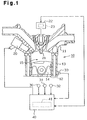
- an engine 10 has a cylinder head 11 and a cylinder block 13 in which a plurality of cylinders 12 (only one shown in Figure 1) are formed.
- a piston 14 is provided in each cylinder 12.
- the piston 14, the inner wall of the cylinder 12 and the cylinder head 11 define a combustion chamber 15.
- Injectors 20, which directly inject fuel into the associated combustion chambers 15, and ignition plugs 21, which ignite the fuel injected from the associated injectors 20, are provided on the cylinder head 11 in association with the cylinders 12.
- Each ignition plug 21 is connected to an associated ignition coil 22.
- the engine 10 is provided with various sensors, which detect the running conditions of the engine and the occurrence of knocking.
- a crank angle sensor 30 and a cam angle sensor 31 are respectively provided near the crankshaft and the cam shaft, which rotates in response to the movement of the crankshaft (neither shaft is shown).
- the crank angle and cam angle sensors 30 and 31 respectively detect the rotational speed of the crankshaft (engine speed NE) and the rotational phase (crank angle CA) thereof.
- a pedal position sensor 32 which detects the degree of pedal depression (pedal depression degree ACCP).
- a knock sensor 33 which outputs a signal according to the magnitude of knocking that occurs in the engine 10 (knocking signal KCS).
- the signals that are output from the individual sensors 30-33 are input to an electronic control unit (ECU) 40 of the engine 10. Based on detection signals from various sensors, including the sensors 30-33 mentioned above, the ECU 40 controls the injectors 20 and the igniters 23 to control the amount of fuel injection, the fuel injection timing and the ignition timing.
- the ECU 40 has a memory 41 that stores programs and operational maps for executing various control procedures and data that is computed when the control procedures are being performed.
- the combustion mode of the engine 10 is switched between stratified-charge combustion and homogeneous-charge combustion by the ECU 40.
- Fuel is injected after the compression stroke of the piston 14. The injected fuel hits the top of the piston 14 and is splashed and unevenly distributed near the ignition plug 21, and the fuel is ignited.
- the air-fuel ratio is set to the stoichiometric air-fuel ratio, and fuel is injected during the suction stroke of the piston 14.
- the fuel which is mixed with air approximately homogeneously, is ignited in the combustion chamber 15.
- the switching of the combustion mode is performed based on parameters, such as the engine load KL and the engine speed NE, which represent the running conditions of the engine. For example, the amount of fuel injection per stroke of the piston 14, which is set based on the pedal depression degree ACCP and the engine speed NE, is used as the engine load KL.
- Figure 2 shows a map that is used in switching the combustion mode.
- the ECU 40 determines the combustion mode that fits the current running conditions of the engine based on the engine load KL and engine speed NE by referring to the map in Figure 2.
- switching the combustion mode is generally controlled based on the engine load KL and the engine speed NE.
- switching the combustion mode is controlled further on the basis of the knocking state, which is acquired through a knocking control procedure.
- FIGS 3(A) and 3(B) are flowcharts illustrating a knocking control routine.
- the ECU 40 executes the routine illustrated in the flowcharts as an interruption process, which is initiated at predetermined crank-angle intervals.
- step S100 shown in Figure 3(A) it is determined whether the currently selected combustion mode is the homogeneous-charge combustion mode.
- the routine is temporarily terminated. That is, in this embodiment, knocking control is not performed during stratified-charge combustion.
- the ignition timing in stratified-charge combustion is set in another routine such that ignition is carried out when the fuel injected from the injector 20 forms an air-fuel mixture layer of a predetermined concentration near the ignition plug 21.
- a basic ignition timing ABSE and a maximum retarding amount AKMAX are computed based on the engine load KL and the engine speed NE in step S110.
- the basic ignition timing ABSE represents the ignition timing at which the maximum engine power is provided for the current running conditions of the engine.
- the basic ignition timing ABSE is indicated in terms of a crank angle CA preceding a reference angle.
- the reference angle corresponds to the top dead center position of the compression stroke.
- the maximum retarding amount AKMAX represents the maximum degree of ignition timing retardation.
- the maximum retarding amount AKMAX is set to a value that guarantees the suppression of knocking for the current running conditions of the engine.
- the relationship of the engine running conditions with the basic ignition timing ABSE and the maximum retardation amount AKMAX (the relationship between the engine load KL and the engine speed NE) has been experimentally predetermined and is stored in the memory 41 of the ECU 40 as data for computing the basic ignition timing ABSE and the maximum retardation amount AKMAX.
- a knock learned value AGKNK is fetched from the memory 41.
- the knock learned value AGKNK is a value advanced from the maximum retardation amount (ABSE - AKMAX) and is obtained by subtracting the maximum retardation amount AKMAX from the basic ignition timing ABSE, in accordance with the knocking state.
- the knock learned value AGKNK is gradually reduced.
- the knock learned value AGKNK is gradually increased. Therefore, the knock learned value AGKNK reflects the frequency of knocking.
- the frequency of knocking varies in accordance with the octane value of the fuel and with the actual compression ratio, which is changed by adhesion of carbon to the cylinder 12.
- a plurality of knock learned values AGKNK are stored in the memory 41, and each knock learned value AGKNK corresponds to a learning area that depends on the engine speed NE.
- each knock learned value AGKNK corresponds to a learning area that depends on the engine speed NE.
- the knock learned value AGKNK is set in accordance with the appropriate learning area because the knocking state varies according to the engine speed NE. Knock suppression is improved by reflecting the difference in the knocking state according to the engine speed NE on the ignition timing.
- step S130 whether or not the engine is knocking is determined based on the knocking signal KCS output from the knock sensor 33.
- the process goes to step S140.
- step S140 a predetermined value ⁇ 1 is added to a current knock control value AKCS and the resultant value (AKCS + ⁇ 1) is set as a new knock control value AKCS.
- the knock control value AKCS serves to correct the ignition timing in accordance with the current knocking occurrence frequency.
- the knock control value AKCS like the knock learned value AGKNK, is renewed in accordance with the knocking state. While the knock learned value AGKNK is gradually updated according to the frequency of occurrence of knocking over a relatively long period of time, the knock control value AKCS is frequently updated according to the occasional occurrence of knocking.
- step S130 When it is determined in step S130 that knocking has not occurred, the process goes to step S145.
- step S145 a predetermined value ⁇ 2 is subtracted from the current knock control value AKCS and the resultant value (AKCS - ⁇ 2) is set as a new knock control value AKCS.
- a final retarding amount AKNK is computed from the following equation 1 in step S150.
- the final retarding amount AKNK is equivalent to the final retarding amount when the basic ignition timing ABSE is retarded.
- AKNK AKMAX - AGKNK + AKCS
- step S160 the knock control value AKCS is compared with a predetermined ⁇ 1 in step S160 shown in Figure 3(B).
- the process advances to step S170.
- step S170 a predetermined value ⁇ is subtracted from the current knock learned value AGKNK and the resultant value (AGKNK - ⁇ ) is set as a new knock learned value AGKNK. Then, the process goes to step S180.
- step S160 When it is determined in step S160 that the knock control value AKCS is equal to or smaller than the predetermined value ⁇ 1, AKCS is compared with a predetermined value ⁇ 2 ( ⁇ 2 ⁇ ⁇ 1) in step S165.
- a predetermined value ⁇ 2 ⁇ 2 ⁇ ⁇ 1
- step S165 When it is determined that the knock control value AKCS is smaller than the predetermined value ⁇ 2, i.e., when the knocking occurrence frequency is smaller than the predetermined frequency, the process advances to step S175.
- step S175 the predetermined value ⁇ is added to the current knock learned value AGKNK and the resultant value (AGKNK + ⁇ ) is set as a new knock learned value AGKNK. Then, the process goes to step S180.
- the decision in step S165 is NO, or when ⁇ 2 ⁇ AKCS ⁇ ⁇ 1 is satisfied, the process goes directly to step S180.
- the knock learned value AGKNK is updated based on the size of the knock control value AKCS, which reflects the knocking occurrence frequency.
- step S180 the updated knock learned value AGKNK is stored in the memory 41 as the value of the learning area that corresponds to the current engine speed NE.
- the final retarding amount AKNK is subtracted from the basic ignition timing ABSE and the resultant value (ABSE - AKNK) is set as a final ignition timing AOP.
- this routine is temporarily terminated.
- the ECU 40 sends the ignition signal based on the final ignition timing AOP to the igniter 23 so that the ignition plug 21 ignites the fuel.
- Figure 4 is a flowchart illustrating steps performed when switching the combustion mode.
- the ECU 40 executes the routine illustrated in Figure 4 as an interruption process at predetermined crank-angle intervals.
- step S200 the current engine speed NE and engine load KL are fetched. Then, the decision value JKL corresponding to the engine speed NE is read from the map shown in Figure 2 in step S210.
- step S230 After the resetting of the decision value JKL, the decision value JKL is compared with the current engine load KL in step S230. When it is determined in step S230 that the engine load KL is less than the decision value JKL, the process goes to step S240. When it is determined in step S240 that the running conditions of the engine lie in the stratified-charge combustion mode area, the combustion mode is set to stratified-charge combustion.
- step S250 it is determined based on the knocking signal KCS if knocking is occurring.
- this routine is temporarily terminated. If no knocking occurs in stratified-charge combustion, therefore, the reduction ratio ⁇ is kept at the initial value of zero. In this case, the decision value JKL is not reset to a smaller value based on the equation 2, so that the stratified-charge combustion mode area is not reduced.
- step S250 When knocking is occurring in step S250, on the other hand, the process goes to step S260 where the reduction ratio ⁇ is set based on the knock learned value AGKNK of the learning area that corresponds to the current engine speed NE.
- Figure 5 is a map showing the relationship between the reduction ratio ⁇ and the knock learned value AGKNK. The smaller the knock learned value AGKNK is, the greater the reduction ratio ⁇ is.
- the engine 10 When the knock learned value AGKNK is small, the engine 10 is likely to knock due to, for example, the use of low octane fuel. Therefore, knocking is inevitable if stratified-charge combustion is performed in the high-load, high-speed engine running area (for example, the area near the solid line in Figure 2).
- the ignition timing is retarded under the knocking control procedure during stratified-charge combustion, as is done in homogeneous-charge combustion, to suppress knocking, the ignition timing would be further retarded from the range where proper combustion occurs. This may result in misfire.
- the reduction ratio ⁇ is stored in the memory 41 of the ECU 40.
- the reduction ratio ⁇ is set to a value other than the initial value.
- the combustion mode is set based on the decision value JKL that has been reset in accordance with the reduction ratio ⁇ . At this time, the combustion mode is switched to homogeneous-charge combustion from stratified-charge combustion, unless the running conditions of the engine have remained unchanged from those of the previous control cycle.
- step S230 When it is determined in step S230 that the engine load KL is equal to or greater than the decision value JKL, the running conditions of the engine are considered to lie in the homogeneous-charge combustion mode area, and the combustion mode is set to homogeneous-charge combustion in step S245.
- step S246 it is determined in step S246 whether the reduction ratio ⁇ is larger than zero, i.e., if the stratified-charge combustion mode area has been reduced from the initial state.
- the process advances to step S260.
- step S260 the reduction ratio ⁇ is set based on the current knock learned value AGKNK, and the new reduction ratio ⁇ is stored in the memory 41.
- the reduction ratio ⁇ is updated even in homogeneous-charge combustion when the stratified-charge combustion mode area is reduced from the initial state.
- the knock learned value AGKNK is increased due to switching to a higher octane fuel, therefore, the reduction ratio ⁇ is reduced according to the octane increase.
- the stratified-charge combustion mode area will be increased again toward the initial state if the state of the engine 10 is shifted to the area where knocking is unlikely to occur.
- the combustion control apparatus has the following advantages.
- the operation of the engine 10 in stratified-charge combustion is restricted based on the knocking state of the engine 10.
- the combustion mode can be set to the homogeneous-charge combustion mode, the range of which for changing the retardation of the ignition timing is wider than that of the stratified-charge combustion mode. Since the combustion mode is switched in accordance with the knocking state, it is unnecessary to change the stratified-charge combustion mode area to an area where knocking does not occur. This permits the ignition timing to be retarded by the degree needed in the knocking control procedure.
- the combustion mode When knocking is detected in the stratified-charge combustion mode, the combustion mode is switched to the homogeneous-charge combustion mode. This allows the ignition timing to be retarded by the degree determined by the knocking control procedure. If knocking is not detected in the stratified-charge combustion mode, the stratified-charge combustion mode area is not reduced and the combustion mode is not changed. This provides more opportunities for performing stratified-charge combustion, which improves fuel efficiency.
- the stratified-charge combustion mode is changed to the homogeneous-charge combustion mode by reducing the stratified-charge combustion mode area based on the reduction ratio ⁇ , which is acquired from the knock learned value AGKNK, and the reduction ratio ⁇ is stored and held in the memory.
- the reduction of the stratified-charge combustion mode area based on the reduction ratio ⁇ continues, and the stratified-charge combustion mode is always determined by the knocking state. It is therefore unnecessary to make occasional changes to the combustion mode according to the knocking state, which prevents frequent changes to the combustion mode.
- the reduction ratio ⁇ is set based on the knock learned value AGKNK, which is renewed during homogeneous-charge combustion. This ensures proper determination of the stratified-charge combustion mode area and the homogeneous-charge combustion mode area in accordance with the knocking state. This properly determines the timing retardation amount according to the demands of the knocking control procedure.
- the reduction ratio ⁇ is updated even during homogeneous-charge combustion if the stratified-charge combustion mode area is reduced from the initial state.
- the knock learned value AGKNK is increased due to, for example, a change in the fuel octane level, therefore, the reduction ratio ⁇ is reduced accordingly. This provides more opportunities to execute stratified-charge combustion to improve fuel efficiency.
- a knock learned value AGKNK is provided for each of a number of learning areas, which are defined in accordance with different engine speeds NE.
- the reduction ratio ⁇ is adequately set to a value corresponding to the learning area of the new engine speed. Therefore, if the knocking state differs according to the engine speed NE, the difference due to a variation in the engine speed NE is reflected when setting each combustion mode area based on the reduction ratio ⁇ .
- the second embodiment differs from the first embodiment shown in Figures 1 to 5 in the following points.
- knocking control is carried out as done in homogeneous-charge combustion mode.
- the knock learned value AGKNK is computed through knocking control in stratified-charge combustion mode.
- the combustion mode is switched to the homogeneous-charge combustion mode from the stratified-charge combustion mode.
- step S100 the decision as to whether or not the current combustion mode is the homogeneous-charge combustion mode (step S100) is omitted. Therefore, a series of processes starting at step S110 is performed, regardless of the combustion mode that is currently selected.
- step S110 the basic ignition timing ABSE and the maximum retarding amount AKMAX are computed based on the currently selected combustion mode in addition to the engine load KL and the engine speed NE.
- step S120 the knock learned value AGKNK stored in the memory 41 is fetched.
- the knock learned value AGKNK is updated for each of plural learning areas that are defined according to the engine speed NE (These learning areas are different from the learning areas used in the homogeneous-charge combustion mode) and the updated knock learned value AGKNK is stored in the memory 41, as is done in the homogeneous-charge combustion mode.
- the engine speed NE and the combustion mode currently selected are referred to.
- steps S130 to S190 are performed as in the first embodiment.
- the knock learned value AGKNK in homogeneous-charge combustion mode is denoted by AGKNKS and the knock learned value AGKNK in stratified-charge combustion mode is denoted by AGKNKT in the following description.
- step S252 the knock learned value AGKNKT in the stratified-charge combustion mode is compared with a decision value JAGKNK.
- the range where the ignition timing can be changed is limited in the stratified-charge combustion mode, as compared with that in the homogeneous-charge combustion mode, there is a limit to the retardation of the ignition timing (final ignition timing AOP) that is accomplished by reducing the knock learned value AGKNKT. If the demanded timing retardation amount is large, a misfire may occur. To avoid such a misfire, the decision value JAGKNK is set to the lower limit at the time of changing the knock learned value AGKNKT. When the knock learned value AGKNKT in stratified-charge combustion mode is greater than the decision value JAGKNK, it is possible to maintain the proper engine combustion without causing a misfire.
- a map that represents the relationship between the decision value JAGKNK and the running conditions of the engine (e.g., the engine load KL and the engine speed NE) is stored in the memory 41 of the ECU 40.
- the decision value JAGKNK is computed by referring to this map.
- step S252 When the knock learned value AGKNKT in stratified-charge combustion mode is greater than the decision value JAGKNK in step S252, this routine is temporarily terminated.
- step S252 the knock learned value AGKNKT is equal to or smaller than the decision value JAGKNK, the process goes to step S262.
- step S262 the knock learned value AGKNKS in homogeneous-charge combustion mode is fetched from the memory 41 and the reduction ratio ⁇ is set based on this knock learned value AGKNKS.
- the combustion mode is switched to the homogeneous-charge combustion mode from the stratified-charge combustion mode unless the running conditions of the engine have remained unchanged from those of the previous control cycle.
- the relationship between the knock learned value AGKNKS and the reduction ratio ⁇ which is similar to that shown in Figure 5, has been experimentally predetermined and is stored in the memory 41.
- step S246 When it is determined in step S246 that the stratified-charge combustion mode area is reduced from the initial state in the homogeneous-charge combustion mode, the reduction ratio ⁇ is set based on the knock learned value AGKNKS in the homogeneous-charge combustion mode and the reduction ratio ⁇ is updated according to the current knocking state in step S262.
- the combustion mode is changed to the homogeneous-charge combustion mode from the stratified-charge combustion mode if the knock learned value AGKNKT in stratified-charge combustion mode is equal to or smaller than the decision value JAGKNK, i.e., if the knocking occurrence frequency is equal to or greater than a predetermined value.
- the combustion mode is changed to the homogeneous-charge combustion mode from the stratified-charge combustion mode only when a demand for the retardation amount of the ignition timing becomes larger through knocking control so that degradation of combustion in the stratified-charge combustion mode is likely to occur.
- reducing the stratified-charge combustion mode area is performed if the knock learned value AGKNKT in the stratified-charge combustion mode has reached the lower limit (decision value JAGKNK) . Therefore, more opportunities for selecting the stratified-charge combustion mode occur in the second embodiment than in the first embodiment, so that the fuel efficiency is improved as much as possible.
- the combustion modes may include a combustion mode having a lower degree of stratification (called a "semi stratified-charge combustion mode") in addition to the stratified-charge combustion mode and the homogeneous-charge combustion mode.
- a combustion mode having a lower degree of stratification called a "semi stratified-charge combustion mode"
- fuel injection can be carried out, for example, during the suction stroke of the piston 14 and after the compression stroke. This makes the difference in fuel concentration between a location near the ignition plug 21 and other locations smaller than that of the stratified-charge combustion mode.
- the stratified-charge combustion mode area When the stratified-charge combustion mode area is reduced, the semi stratified-charge combustion mode area is also reduced. When each combustion mode area is reduced, it is possible to set the reduction ratio to the same value or different values between the stratified-charge combustion mode and the semi stratified-charge combustion mode.
- another map in which the stratified-charge combustion mode area is smaller than that in the normal state may be prepared in advance so that the map being used is changed from a normal state map to this additional map when the stratified-charge combustion mode area is reduced.
- the map for determining the combustion mode is set back to the normal state map when the knock learned value AGKNKS in homogeneous-charge combustion mode becomes equal to or greater than the predetermined value.
- Step S246 in Figures 4 and 6 may be omitted so that the process is terminated after step S245.
- the process of updating the reduction ratio ⁇ during homogeneous-charge combustion may be omitted.
- the reduction ratio ⁇ may be reset to the initial value of zero when the engine 10 stops running.
- An engine performs a combustion mode selected from a plurality of combustion modes.
- the combustion modes include stratified-charge combustion and homogeneous-charge combustion.
- a electronic control unit switches the combustion mode in accordance with the current running conditions of the engine.
- the electronic control unit limits a running area in which stratified-charge combustion is performed in accordance with the frequency of engine knocking occurrences. This properly executes knocking control without adversely affecting the execution of stratified-charge combustion.
Landscapes
- Engineering & Computer Science (AREA)
- Chemical & Material Sciences (AREA)
- Combustion & Propulsion (AREA)
- Mechanical Engineering (AREA)
- General Engineering & Computer Science (AREA)
- Signal Processing (AREA)
- Electrical Control Of Ignition Timing (AREA)
- Electrical Control Of Air Or Fuel Supplied To Internal-Combustion Engine (AREA)
- Combined Controls Of Internal Combustion Engines (AREA)
Abstract
Description
Claims (9)
- An apparatus for controlling combustion in an engine (10) that produces power by burning a mixture of air and fuel in a combustion chamber (15), wherein the engine (10) performs a mode of combustion selected from a plurality of combustion modes, the combustion modes being stratified-charge combustion, in which the mixture is distributed in a concentrated manner in the combustion chamber (15), and homogeneous-charge combustion, in which the mixture is distributed in a homogeneous manner in the combustion chamber (15), wherein the apparatus includes means for switching the combustion mode in accordance with current running conditions of the engine (10), the apparatus being characterized by:a controller for limiting a running area in which stratified-charge combustion is selected in accordance with the occurrence of engine (10) knocking.
- The apparatus according to claim 1, characterized by the controller includes:a detector for detecting knocking; andmeans for changing the combustion mode from stratified-charge combustion to homogeneous-charge combustion when the detector detects knocking during stratified-charge combustion.
- The apparatus according to claim 1, characterized by the controller further includes:a detector for detecting knocking;means for judging whether the value of the frequency of occurrence of knocking is equal to or greater than a predetermined value during stratified-charge combustion in accordance with the value detected by the detector; andmeans for changing the combustion mode from stratified-charge combustion to homogeneous-charge combustion when the frequency of occurrence of knocking is equal to or greater than the predetermined value.
- The apparatus according to claims 2 or 3, characterized in that the controller changes the combustion mode to stratified-charge combustion when the running conditions of the engine (10) are within the stratified-charge combustion running area and changes the combustion mode to homogeneous-charge combustion when the running conditions of the engine (10) are outside of the stratified-charge combustion running area.
- The apparatus according to claim 4, characterized in that the changing means reduces the stratified-charge combustion running area to change the combustion mode from stratified-charge combustion to homogeneous-charge combustion and memorizes the reduced running area.
- The apparatus according to claim 5, characterized in that the changing means stores the frequency of knocking occurrences during homogeneous-charge combustion in accordance with the value detected by the detector and sets a reduction ratio, which is used to reduce the stratified-charge combustion running area in accordance with the stored knocking frequency.
- The apparatus according to claim 6, characterized in that, when the stratified-charge combustion running area is reduced, the reduction ratio is always updated.
- The apparatus according to claim 1, characterized in that the combustion modes further include semi-stratified-charge combustion, which has characteristics of both stratified-charge combustion and homogeneous-charge combustion, and wherein the controller limits a running area in which semi-stratified-charge combustion is selected in accordance with the occurrence of engine (10) knocking.
- A method for controlling combustion in an engine (10) that produces power by burning a mixture of air and fuel in a combustion chamber (15), wherein the engine (10) performs a combustion mode selected from a plurality of combustion modes, the combustion modes being stratified-charge combustion, in which the mixture is distributed in a concentrated manner in the combustion chamber (15), and homogeneous-charge combustion, in which the mixture is distributed in a homogeneous manner in the combustion chamber (15), wherein the method includes switching the combustion mode in accordance with current running conditions of the engine (10), the method being characterized by:limiting a running area of stratified-charge combustion in accordance with the frequency of engine (10) knocking occurrences.
Applications Claiming Priority (2)
| Application Number | Priority Date | Filing Date | Title |
|---|---|---|---|
| JP23990499A JP3587097B2 (en) | 1999-08-26 | 1999-08-26 | Combustion control device for internal combustion engine |
| JP23990499 | 1999-08-26 |
Publications (3)
| Publication Number | Publication Date |
|---|---|
| EP1079088A2 true EP1079088A2 (en) | 2001-02-28 |
| EP1079088A3 EP1079088A3 (en) | 2003-04-02 |
| EP1079088B1 EP1079088B1 (en) | 2006-06-14 |
Family
ID=17051591
Family Applications (1)
| Application Number | Title | Priority Date | Filing Date |
|---|---|---|---|
| EP00118388A Expired - Lifetime EP1079088B1 (en) | 1999-08-26 | 2000-08-24 | Engine combustion control apparatus and method |
Country Status (4)
| Country | Link |
|---|---|
| US (1) | US6371076B1 (en) |
| EP (1) | EP1079088B1 (en) |
| JP (1) | JP3587097B2 (en) |
| DE (1) | DE60028667T2 (en) |
Cited By (2)
| Publication number | Priority date | Publication date | Assignee | Title |
|---|---|---|---|---|
| EP1950404A4 (en) * | 2005-11-14 | 2009-12-23 | Toyota Motor Co Ltd | CONTROL FOR A COMBUSTION ENGINE |
| WO2010108777A1 (en) * | 2009-03-26 | 2010-09-30 | Robert Bosch Gmbh | Method for operating an internal combustion engine, control device for an internal combustion engine and internal combustion engine with direct injection |
Families Citing this family (6)
| Publication number | Priority date | Publication date | Assignee | Title |
|---|---|---|---|---|
| US6705276B1 (en) | 2002-10-24 | 2004-03-16 | Ford Global Technologies, Llc | Combustion mode control for a direct injection spark ignition (DISI) internal combustion engine |
| JPWO2006070459A1 (en) * | 2004-12-28 | 2008-06-12 | ヤマハマリン株式会社 | Ship engine knock control device |
| JP5554295B2 (en) * | 2011-07-28 | 2014-07-23 | 日立オートモティブシステムズ株式会社 | Combustion noise detection method, combustion noise detection apparatus and control apparatus for internal combustion engine |
| JP5726697B2 (en) * | 2011-09-29 | 2015-06-03 | 本田技研工業株式会社 | Engine ignition timing control device |
| EP3009646B1 (en) | 2013-06-11 | 2018-07-04 | Nissan Motor Company, Limited | Internal combustion engine control device, and control method |
| CA2978532C (en) * | 2015-03-04 | 2019-03-26 | Nissan Motor Co., Ltd. | Internal combustion engine control device and internal combustion engine control method |
Family Cites Families (9)
| Publication number | Priority date | Publication date | Assignee | Title |
|---|---|---|---|---|
| JPH04353243A (en) | 1991-05-29 | 1992-12-08 | Fuji Heavy Ind Ltd | Combustion control device |
| DE19612150A1 (en) * | 1996-03-27 | 1997-10-02 | Bosch Gmbh Robert | Control device for fuel-injected engine |
| JP3233039B2 (en) * | 1996-08-28 | 2001-11-26 | 三菱自動車工業株式会社 | Control device for in-cylinder injection spark ignition internal combustion engine |
| JP3317166B2 (en) | 1996-11-26 | 2002-08-26 | トヨタ自動車株式会社 | Knock determination device for internal combustion engine |
| JP3189734B2 (en) * | 1996-12-19 | 2001-07-16 | 三菱自動車工業株式会社 | Spark ignition direct injection internal combustion engine |
| JP3198957B2 (en) | 1996-12-19 | 2001-08-13 | トヨタ自動車株式会社 | Output fluctuation suppression control device for lean burn internal combustion engine |
| JP3813332B2 (en) * | 1997-10-27 | 2006-08-23 | 三菱電機株式会社 | In-cylinder injection fuel control system for internal combustion engine |
| JPH11182288A (en) * | 1997-12-18 | 1999-07-06 | Sanshin Ind Co Ltd | Control device for direct fuel injection type engine |
| DE19859424A1 (en) * | 1998-12-22 | 2000-06-29 | Bosch Gmbh Robert | Fuel injection process |
-
1999
- 1999-08-26 JP JP23990499A patent/JP3587097B2/en not_active Expired - Fee Related
-
2000
- 2000-08-10 US US09/636,260 patent/US6371076B1/en not_active Expired - Fee Related
- 2000-08-24 EP EP00118388A patent/EP1079088B1/en not_active Expired - Lifetime
- 2000-08-24 DE DE60028667T patent/DE60028667T2/en not_active Expired - Lifetime
Cited By (3)
| Publication number | Priority date | Publication date | Assignee | Title |
|---|---|---|---|---|
| EP1950404A4 (en) * | 2005-11-14 | 2009-12-23 | Toyota Motor Co Ltd | CONTROL FOR A COMBUSTION ENGINE |
| US8688356B2 (en) | 2005-11-14 | 2014-04-01 | Toyota Jidosha Kabushiki Kaisha | Control device for internal combustion engine |
| WO2010108777A1 (en) * | 2009-03-26 | 2010-09-30 | Robert Bosch Gmbh | Method for operating an internal combustion engine, control device for an internal combustion engine and internal combustion engine with direct injection |
Also Published As
| Publication number | Publication date |
|---|---|
| US6371076B1 (en) | 2002-04-16 |
| JP2001065401A (en) | 2001-03-16 |
| JP3587097B2 (en) | 2004-11-10 |
| DE60028667T2 (en) | 2007-05-16 |
| DE60028667D1 (en) | 2006-07-27 |
| EP1079088B1 (en) | 2006-06-14 |
| EP1079088A3 (en) | 2003-04-02 |
Similar Documents
| Publication | Publication Date | Title |
|---|---|---|
| US5819701A (en) | Control system for two cycle direct injection engine and the method thereof | |
| KR100674251B1 (en) | Knocking judgment device of internal combustion engine | |
| JP3216139B2 (en) | Control device for in-cylinder injection internal combustion engine | |
| US6973910B2 (en) | Fuel injection control apparatus and fuel injection control method for internal combustion engine | |
| EP1083327B1 (en) | Fuel injection controller for in-cylinder injection engine | |
| JPH11210536A (en) | Fuel control system for multi-cylinder engine | |
| US6925987B2 (en) | Method for setting a knock determination period in an internal combustion engine, method for setting a fuel injection timing in an internal combustion engine, and control apparatus for an internal combustion engine | |
| US6499460B2 (en) | Ignition timing control device for internal combustion engine | |
| EP1079088B1 (en) | Engine combustion control apparatus and method | |
| JP4038999B2 (en) | Control device for direct-injection spark ignition engine | |
| JP2002174135A (en) | Compression self-ignition internal combustion engine | |
| JP3799937B2 (en) | Control device for continuously variable transmission | |
| JP2009191663A (en) | Fuel injection control device for internal combustion engine | |
| JP2009079545A (en) | Variable compression ratio internal combustion engine | |
| JP2005016343A (en) | Control device for compression ignition type internal combustion engine | |
| JP2002089321A (en) | Combustion control device for in-cylinder injection internal combustion engine | |
| KR100412642B1 (en) | A knocking control method for a vehicle | |
| KR100241042B1 (en) | Control device for cylinder injection type internal-combustion engine | |
| JP2007023971A (en) | Ignition timing control device for internal combustion engine | |
| JP2000073825A (en) | Fuel injection device for engine | |
| JP2020016162A (en) | Fuel control device for internal combustion engine | |
| JP2003336569A (en) | Internal combustion engine | |
| JP2000009006A (en) | Ignition timing control device for internal combustion engine | |
| JP2007278088A (en) | Fuel injection control device for internal combustion engine |
Legal Events
| Date | Code | Title | Description |
|---|---|---|---|
| PUAI | Public reference made under article 153(3) epc to a published international application that has entered the european phase |
Free format text: ORIGINAL CODE: 0009012 |
|
| 17P | Request for examination filed |
Effective date: 20000824 |
|
| AK | Designated contracting states |
Kind code of ref document: A2 Designated state(s): AT BE CH CY DE DK ES FI FR GB GR IE IT LI LU MC NL PT SE |
|
| AX | Request for extension of the european patent |
Free format text: AL;LT;LV;MK;RO;SI |
|
| PUAL | Search report despatched |
Free format text: ORIGINAL CODE: 0009013 |
|
| AK | Designated contracting states |
Kind code of ref document: A3 Designated state(s): AT BE CH CY DE DK ES FI FR GB GR IE IT LI LU MC NL PT SE |
|
| AX | Request for extension of the european patent |
Extension state: AL LT LV MK RO SI |
|
| AKX | Designation fees paid |
Designated state(s): DE FR GB IT |
|
| GRAP | Despatch of communication of intention to grant a patent |
Free format text: ORIGINAL CODE: EPIDOSNIGR1 |
|
| GRAS | Grant fee paid |
Free format text: ORIGINAL CODE: EPIDOSNIGR3 |
|
| GRAA | (expected) grant |
Free format text: ORIGINAL CODE: 0009210 |
|
| AK | Designated contracting states |
Kind code of ref document: B1 Designated state(s): DE FR GB IT |
|
| REG | Reference to a national code |
Ref country code: GB Ref legal event code: FG4D |
|
| REF | Corresponds to: |
Ref document number: 60028667 Country of ref document: DE Date of ref document: 20060727 Kind code of ref document: P |
|
| ET | Fr: translation filed | ||
| PLBE | No opposition filed within time limit |
Free format text: ORIGINAL CODE: 0009261 |
|
| STAA | Information on the status of an ep patent application or granted ep patent |
Free format text: STATUS: NO OPPOSITION FILED WITHIN TIME LIMIT |
|
| 26N | No opposition filed |
Effective date: 20070315 |
|
| REG | Reference to a national code |
Ref country code: GB Ref legal event code: 746 Effective date: 20091103 |
|
| PGFP | Annual fee paid to national office [announced via postgrant information from national office to epo] |
Ref country code: DE Payment date: 20110817 Year of fee payment: 12 Ref country code: FR Payment date: 20110818 Year of fee payment: 12 Ref country code: GB Payment date: 20110824 Year of fee payment: 12 |
|
| PGFP | Annual fee paid to national office [announced via postgrant information from national office to epo] |
Ref country code: IT Payment date: 20110823 Year of fee payment: 12 |
|
| GBPC | Gb: european patent ceased through non-payment of renewal fee |
Effective date: 20120824 |
|
| REG | Reference to a national code |
Ref country code: FR Ref legal event code: ST Effective date: 20130430 |
|
| PG25 | Lapsed in a contracting state [announced via postgrant information from national office to epo] |
Ref country code: IT Free format text: LAPSE BECAUSE OF NON-PAYMENT OF DUE FEES Effective date: 20120824 |
|
| PG25 | Lapsed in a contracting state [announced via postgrant information from national office to epo] |
Ref country code: DE Free format text: LAPSE BECAUSE OF NON-PAYMENT OF DUE FEES Effective date: 20130301 Ref country code: GB Free format text: LAPSE BECAUSE OF NON-PAYMENT OF DUE FEES Effective date: 20120824 |
|
| PG25 | Lapsed in a contracting state [announced via postgrant information from national office to epo] |
Ref country code: FR Free format text: LAPSE BECAUSE OF NON-PAYMENT OF DUE FEES Effective date: 20120831 |
|
| REG | Reference to a national code |
Ref country code: DE Ref legal event code: R119 Ref document number: 60028667 Country of ref document: DE Effective date: 20130301 |