EP1079081A2 - Direct-fuel-injection-type spark-ignition internal combustion engine and method of fuel injection - Google Patents
Direct-fuel-injection-type spark-ignition internal combustion engine and method of fuel injection Download PDFInfo
- Publication number
- EP1079081A2 EP1079081A2 EP00118020A EP00118020A EP1079081A2 EP 1079081 A2 EP1079081 A2 EP 1079081A2 EP 00118020 A EP00118020 A EP 00118020A EP 00118020 A EP00118020 A EP 00118020A EP 1079081 A2 EP1079081 A2 EP 1079081A2
- Authority
- EP
- European Patent Office
- Prior art keywords
- fuel
- side wall
- cavity
- injection
- ignition
- Prior art date
- Legal status (The legal status is an assumption and is not a legal conclusion. Google has not performed a legal analysis and makes no representation as to the accuracy of the status listed.)
- Granted
Links
Images

Classifications
-
- F—MECHANICAL ENGINEERING; LIGHTING; HEATING; WEAPONS; BLASTING
- F02—COMBUSTION ENGINES; HOT-GAS OR COMBUSTION-PRODUCT ENGINE PLANTS
- F02F—CYLINDERS, PISTONS OR CASINGS, FOR COMBUSTION ENGINES; ARRANGEMENTS OF SEALINGS IN COMBUSTION ENGINES
- F02F1/00—Cylinders; Cylinder heads
- F02F1/24—Cylinder heads
- F02F1/42—Shape or arrangement of intake or exhaust channels in cylinder heads
- F02F1/4214—Shape or arrangement of intake or exhaust channels in cylinder heads specially adapted for four or more valves per cylinder
-
- F—MECHANICAL ENGINEERING; LIGHTING; HEATING; WEAPONS; BLASTING
- F02—COMBUSTION ENGINES; HOT-GAS OR COMBUSTION-PRODUCT ENGINE PLANTS
- F02B—INTERNAL-COMBUSTION PISTON ENGINES; COMBUSTION ENGINES IN GENERAL
- F02B23/00—Other engines characterised by special shape or construction of combustion chambers to improve operation
- F02B23/08—Other engines characterised by special shape or construction of combustion chambers to improve operation with positive ignition
- F02B23/10—Other engines characterised by special shape or construction of combustion chambers to improve operation with positive ignition with separate admission of air and fuel into cylinder
- F02B23/104—Other engines characterised by special shape or construction of combustion chambers to improve operation with positive ignition with separate admission of air and fuel into cylinder the injector being placed on a side position of the cylinder
- F02B23/105—Other engines characterised by special shape or construction of combustion chambers to improve operation with positive ignition with separate admission of air and fuel into cylinder the injector being placed on a side position of the cylinder the fuel is sprayed directly onto or close to the spark plug
-
- F—MECHANICAL ENGINEERING; LIGHTING; HEATING; WEAPONS; BLASTING
- F02—COMBUSTION ENGINES; HOT-GAS OR COMBUSTION-PRODUCT ENGINE PLANTS
- F02B—INTERNAL-COMBUSTION PISTON ENGINES; COMBUSTION ENGINES IN GENERAL
- F02B23/00—Other engines characterised by special shape or construction of combustion chambers to improve operation
- F02B23/08—Other engines characterised by special shape or construction of combustion chambers to improve operation with positive ignition
- F02B23/10—Other engines characterised by special shape or construction of combustion chambers to improve operation with positive ignition with separate admission of air and fuel into cylinder
- F02B2023/103—Other engines characterised by special shape or construction of combustion chambers to improve operation with positive ignition with separate admission of air and fuel into cylinder the injector having a multi-hole nozzle for generating multiple sprays
-
- F—MECHANICAL ENGINEERING; LIGHTING; HEATING; WEAPONS; BLASTING
- F02—COMBUSTION ENGINES; HOT-GAS OR COMBUSTION-PRODUCT ENGINE PLANTS
- F02B—INTERNAL-COMBUSTION PISTON ENGINES; COMBUSTION ENGINES IN GENERAL
- F02B75/00—Other engines
- F02B75/12—Other methods of operation
- F02B2075/125—Direct injection in the combustion chamber for spark ignition engines, i.e. not in pre-combustion chamber
-
- Y—GENERAL TAGGING OF NEW TECHNOLOGICAL DEVELOPMENTS; GENERAL TAGGING OF CROSS-SECTIONAL TECHNOLOGIES SPANNING OVER SEVERAL SECTIONS OF THE IPC; TECHNICAL SUBJECTS COVERED BY FORMER USPC CROSS-REFERENCE ART COLLECTIONS [XRACs] AND DIGESTS
- Y02—TECHNOLOGIES OR APPLICATIONS FOR MITIGATION OR ADAPTATION AGAINST CLIMATE CHANGE
- Y02T—CLIMATE CHANGE MITIGATION TECHNOLOGIES RELATED TO TRANSPORTATION
- Y02T10/00—Road transport of goods or passengers
- Y02T10/10—Internal combustion engine [ICE] based vehicles
- Y02T10/12—Improving ICE efficiencies
Definitions
- the invention relates to a direct-fuel-injection-type spark-ignition internal combustion engine having, in an upper wall of a cylinder, a cavity for forming a combustible air-fuel mixture, and to a method of injecting fuel with such an engine.
- a direct-fuel-injection-type spark-ignition internal combustion engine having a fuel injection valve for injecting fuel directly into a cylinder injects fuel into a cavity formed in a top surface of a piston during a late period of the compression stroke so as to vaporize fuel using heat from the piston and to guide the vaporized fuel to the vicinity of an ignition plug so that, at the time of ignition, a combustible air-fuel mixture with a good ignition quality is formed only in the vicinity of the ignition plug.
- the engine thus realizes stratified charge combustion that allows combustion of a mixture that is fuel-lean in terms of the entire cylinder.
- a direct-fuel-injection-type spark-ignition internal combustion engine provides a good stratified charge combustion by reliably positioning a main portion of an air-fuel mixture near an ignition plug at the time of ignition in a direct-fuel-injection-type spark-ignition internal combustion engine having, in an upper cylinder wall, a cavity for forming a combustible mixture.
- a direct-fuel-injection-type spark-ignition internal combustion engine includes an ignition plug, a cavity formed in an upper wall of a cylinder, and a fuel injection valve that injects fuel so that most of the fuel strikes a side wall of the cavity at an acute angle with respect to a tangent to the side wall at the point where the fuel strikes the side wall.
- the side wall of the cavity has a fuel guide portion. Most of the fuel is guided along the fuel guide portion to the vicinity of the ignition plug.
- the direct-fuel-injection-type spark-ignition internal combustion engine of the invention is able to reliably position a main portion of combustible mixture in the vicinity of the ignition plug at the time of ignition and therefore realize a good stratified charge combustion.
- the fuel injection valve may inject the main portion of the fuel separately in two directions.
- portions of the main portion of the fuel injected in the two directions are guided along the fuel guide portion to the vicinity of the ignition plug so as to face each other.
- At least a portion of the fuel guide portion may be adjacent to an intake port opening formed in the upper wall of the cylinder.
- At least a portion of the fuel guide portion may be adjacent to an exhaust port opening formed in the upper wall of the cylinder.
- the fuel guide portion may have a barrier portion that a liquid fuel moving along the fuel guide portion strikes in the vicinity of the ignition plug.
- the fuel injection valve may inject the fuel as a generally flat sector-shaped (i.e. fan-shaped) fuel spray having a small thickness.
- a central portion of the sector-shaped fuel spray in a direction of a width of the sector-shaped fuel spray is directed substantially toward a center axis of the ignition plug.
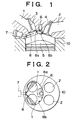
- FIGURE 1 is a schematic longitudinal sectional view, illustrating a first embodiment of the direct-fuel-injection-type spark-ignition internal combustion engine of the invention.
- FIGURE 2 is a bottom plan view of an upper portion of a cylinder 10 in the first embodiment.
- an upper portion of the cylinder 10 of the direct-fuel-injection-type spark-ignition internal combustion engine is provided with intake ports 1 and exhaust ports 2.
- the intake ports 1 and the exhaust ports 2 communicate with the cylinder 10 via intake valves 3 and exhaust valves 4, respectively.
- a piston 5 is disposed in the cylinder 10.
- a cavity 8 is formed in the cylinder upper portion.
- the two intake ports 1 open to an upper wall 8a of the cavity 8.
- an ignition plug 6 protrudes from the upper wall 8a of the cavity 8.
- the ignition plug 6 is positioned substantially at a center of the upper portion of the cylinder 10.
- a side wall 8b of the cavity 8 extends surrounding the two intake ports 1 and the ignition plug 6.
- the side wall 8b extends through the vicinity of the ignition plug 6.
- a fuel injection valve 7 is positioned in a portion of the side wall 8b of the cavity 8 that is opposite and remote from the ignition plug 6.
- the fuel injection valve 7 has a slit-like injection hole for injecting fuel in the shape of a sector having a small thickness or height.
- the fuel injection valve 7 in this embodiment has two slit-like injection holes for injecting fuel in two directions as indicated by hatching in FIGURE 2 in such a manner that the thickness of each sector-shaped (i.e. fan-sharped) fuel spray substantially equals the height of the side wall 8b of the cavity 8.
- the fuel injecting directions and the shape of the side wall 8b of the cavity 8 are set so that each portion of fuel injected from the fuel injection valve 7 in the two directions strikes the side wall 8b of the cavity 8 at an acute angle with respect to a tangent to the side wall 8b at the point where the fuel strikes the side wall 8b.
- a cross-sectional shape of the side wall 8b of the cavity 8 is generally symmetric about a vertical plane that includes a center axis of the fuel injection valve 7 and a center axis of the ignition plug 6.
- the fuel injection valve 7 injects sector-shaped fuel sprays in two directions that are generally symmetric to each other about the vertical plane.
- a portion of the side wall 8b serves as a fuel guide portion for guiding fuel to the vicinity of the ignition plug 6. Due to the above-described construction in this embodiment, the distances from the two fuel impact positions on the side wall 8b to a position adjacent to the ignition plug 6 substantially equal each other. Therefore, injected liquid fuel sprays indicated by hatching in FIGURE 2, after striking the side wall 8b, gradually vaporize with heat received during movement along the fuel guide portion toward the ignition plug 6, and then collide each other when reaching the vicinity of the ignition plug 6.
- a combustible air-fuel mixture is formed at a location indicated by a dotted area in FIGURE 2.
- the fuel guide portion perpendicularly intersects a center plane of the height of the fuel sprays, so that liquid fuel moving along the fuel guide portion does not flow out of the cavity but the entire amount of fuel injected forms a combustible mixture.
- the fuel injection valve 7 is able to inject fuel during an early period of the compression stroke regardless of the position of the piston 5. Hence, it becomes possible to inject a relatively large amount of fuel.
- the fuel guide portion of the side wall 8b of the cavity 8 undergoes a temperature drop due to vaporization of the large amount of fuel, so that the heat transferred from the fuel guide portion to the fuel may become insufficient and liquid fuel may reach the vicinity of the ignition plug 6.
- the liquid fuel turns into fine particles, and then easily vaporizes. Therefore, even when a relatively large amount of fuel is injected, a combustible mixture can be formed in the vicinity of the ignition plug 6.
- fuel is injected during the intake stroke to perform uniform combustion. Since a portion of the fuel guide portion of the side wall 8b of the cavity 8 is adjacent to the cylinder-side openings of the intake ports 1, fuel injected from the fuel injection valve 7, while traveling across the cylinder-side openings of the intake ports 1, is stirred by intake air flows from the cylinder-side openings of the intake ports 1 during the uniform combustion operation. Furthermore, fuel that has reached the fuel guide portion is well stirred by intake flows moving along the fuel guide portion. Thus, a sufficiently homogenized uniform mixture is formed in the cylinder at the time of ignition, so that a good uniform combustion can be realized.
- the fuel injection valve 7 injects fuel in the two directions and the two portions of fuel are guided by the fuel guide portion of the side wall 8b of the cavity 8 so as to collide with each other in the vicinity of the ignition plug 6.
- fuel in one direction.
- fuel injected during a stratified charge combustion operation forms a combustible mixture in a narrow-and-long shape moving along the side wall 8b of the cavity 8.
- the combustible mixture in a narrow-and-long shape achieves a relatively-long-time contact with an ignition gap of the ignition plug 6, during which ignition and combustion can be performed. Therefore, the fuel injection timing and the ignition timing can be relatively freely set.
- a portion of the fuel guide portion of the side wall 8b of the cavity 8 is adjacent to the cylinder-side openings of the intake ports 1, so that a good uniform combustion can be performed as described above.
- the side wall 8b of the cavity 8 extends surrounding the ignition plug 6 and the cylinder-side openings of the two intake ports 1, the side wall 8b of the cavity 8 may surround only one intake port and an ignition plug in either a single-intake-valve construction or a dual-intake-valve construction.
- FIGURE 3 is a bottom plan view of an upper portion of a cylinder 10, illustrating a second embodiment of the direct-fuel-injection-type spark-ignition internal combustion engine of the invention.
- the same reference numerals as those used for the first embodiment represent the same component elements. Differences from the first embodiment will mainly be described below.
- a side wall 18b of a cavity 18 extends surrounding cylinder-side openings of two intake ports 1 and an ignition plug 6 as in the first embodiment.
- the side wall 18b has a plug pocket portion 18c that surrounds at least a half of the periphery of the ignition plug 6.
- a fuel injection valve 7' injects fuel in one direction as indicated by hatching in FIGURE 3 in such a manner that the direction of the thickness of the fuel spray substantially equals the direction of the height of the side wall 18b of the cavity 18. And, the fuel injection 7 ' injects fuel in such manner that the thickness of the fuel spray is thinner than the height of the side wall 18b of cavity 18.
- the fuel injecting direction and the shape of the side wall 18b of the cavity 18 are set so that each fuel portion strikes the side wall 18b of the cavity 18 at an acute angle with respect to a tangent of the side wall 18b at the point where the fuel strikes the side wall 18b.
- FIGURE 4 is an enlarged view illustrating the shape of the plug pocket portion 18c.
- a fuel guide portion of the side wall 18b of the cavity 18 extends from a position of impact of fuel injected from the fuel injection valve 7' on the side wall 18b to the plug pocket portion 18c.
- a portion of the side wall 18b of the cavity 18 that extends from the plug pocket portion 18c on the side opposite from the fuel guide portion is formed so that an imaginary extended plane of the fuel guide portion intersects the wall surface of the plug pocket portion 18c.
- liquid fuel as indicated by hatching in FIGURE 3, after striking the side wall 18b of the cavity 18, moves along the fuel guide portion and reaches the plug pocket portion 18c by its own inertia.
- Fuel vaporizes during movement along the fuel guide portion due to heat from the fuel guide portion, and then enters the plug pocket portion 18c as indicated by an arrow of a one-dot chain line due to the Coanda effect, and also spreads outside the opening of the plug pocket portion 18c, thus forming a combustible mixture as indicated by a dotted area in FIGURE 4 in the vicinity of the ignition plug 6.
- the thus-formed combustible mixture resides in the vicinity of the ignition plug 6 since there is no factor that causes the mixture to move from the vicinity of the ignition plug 6, so that ignition and combustion can be performed at any time. Therefore, it is possible to freely set the fuel injection timing and the ignition timing and to reliably position a combustible mixture in the vicinity of the ignition plug at the time of ignition regardless of engine revolution speed even if a relatively large amount of fuel is injected. Thus, a good stratified charge combustion can be realized. As a result, the operational range of stratified charge combustion that achieves a reduced specific fuel consumption can be reliably expanded toward the high-speed/high-load operation side.
- FIGURE 5 is an enlarged view of a plug pocket portion 18c' according to a modification of the plug pocket portion of FIGS. 3 and 4.
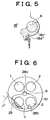
- the plug pocket portion 18c' has, at a terminal end of the fuel guide portion contiguous to the plug pocket portion 18c', a barrier 18d' protruding inwardly with respect to the cavity 18'. Due to this construction, fuel vaporized during movement along the fuel guide portion is temporarily directed inwardly with respect to the cavity 18' by the barrier 18d', but is immediately caused to form a combustible mixture as indicated by a dotted area in FIGURE 6 in the vicinity of the plug pocket 18c' due to the Coanda effect.
- the liquid fuel turns into fine particles at the time of impact of the liquid fuel, and therefore readily vaporizes.
- the particle forming position is also in the vicinity of the ignition plug 6. Therefore, vaporized fuel from fine particles joins fuel vaporized by heat received from the fuel guide portion to form a combustible mixture in the vicinity of the ignition plug 6.
- the barrier 18d' is also effective for a cavity 8 having no plug pocket as shown in FIGS. 1 and 2. If a barrier is provided in the fuel guide portion, more specifically, at a location slightly before the ignition plug 6, liquid fuel and vaporized fuel can be prevented from passing by the ignition plug 6. This is advantageous to reliably position a combustible mixture in the vicinity of the ignition plug 6 at the time of ignition. Furthermore, if a barrier is provided in the fuel guide portion, at a location slightly before the ignition plug 6, it becomes possible to prevent passage of liquid fuel and vaporized fuel by the ignition plug 6 and prevent direct impact of liquid fuel on the ignition plug 6.
- FIGURE 6 is a bottom plan view of an upper portion of a cylinder 10, illustrating a third embodiment of the direct-fuel-injection-type spark-ignition internal combustion engine of the invention.
- a side wall 28b of a cavity 28 extends surrounding an ignition plug 6 and cylinder-side openings of an intake port 1 and an exhaust port 2 that are adjacent to each other.
- the side wall 28b has a plug pocket portion 28c similar to those of FIGS. 3-5.
- a fuel injection valve 7' injects fuel so that fuel strikes a portion of the side wall 28b of the cavity 28 adjacent to the intake port 1 as indicated by hatching in FIGURE 6.
- the third embodiment achieves substantially the same advantages as those of FIGS. 3-5. Furthermore, since the fuel guide portion of the side wall 28b of the cavity 28 is partially located adjacent to the cylinder-side opening of the intake port 1 and adjacent to the cylinder-side opening of the exhaust port 2, the temperature of the fuel guide portion is increased, so that fuel, moving along the fuel guide portion can be more favorably vaporized. Therefore, it becomes possible to further increase the amount of fuel injected during the compression stroke and therefore reliably expand the operational range of stratified charge combustion, which achieves a low specific fuel consumption, toward the high-speed/high-load operation side.
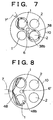
- FIGURE 7 is a bottom plan view of an upper portion of a cylinder 10, illustrating a fourth embodiment of the direct-fuel-injection-type spark-ignition internal combustion engine of the invention.
- the same reference numerals as those used for the foregoing embodiments represent the same component elements. Differences from the second embodiment will be mainly described.
- a side wall 38b of a cavity 38 extends generally in the shape of a figure "8" so as to surround an ignition plug 6 and cylinder-side openings of an intake port 1 and an exhaust port 2 that are opposite to each other on a diagonal line.
- a fuel injection valve 7' injects fuel so that fuel strikes a portion of the side wall 38b of the cavity 38 adjacent to the intake port 1 as indicated by hatching in FIGURE 7.
- injected fuel does not entirely turn into a combustible mixture by the time it has passed along a portion of the fuel guide portion adjacent to the cylinder-side opening of the intake port 1. Injected fuel turns entirely into a combustible mixture during the passage along a portion of the fuel guide portion adjacent to the cylinder-side opening of the exhaust port 2. The ignition and combustion of the combustible mixture is possible when the mixture passes by the ignition plug 6 again. In this case, a relatively long portion of the fuel guide portion is adjacent to the cylinder-side opening of the exhaust port 2, so that the temperature of the adjacent portion of the fuel guide portion becomes high and a relatively large amount of fuel can be sufficiently vaporized.
- FIGURE 8 is a bottom plan view of an upper portion of a cylinder 10, illustrating a fifth embodiment of the direct-fuel-injection-type spark-ignition internal combustion engine of the invention.
- the same reference numerals as those used for the foregoing embodiments represent the same component elements. Differences from the first embodiment will be mainly described.
- a side wall 48b of a cavity 48 extends so as to surround the cylinder-side openings of two intake ports 1 and an ignition plug 6'. However, the ignition plug 6' is offset from the center of the cylinder 10 to the side of the intake ports 1, so that relatively long portions of a fuel guide portion of the side wall 48b are adjacent to the cylinder-side openings of the two intake ports 1.
- the fifth embodiment achieves substantially the same advantages as those of FIGS. 1 and 2. Furthermore, the fifth embodiment allows good contact between injected fuel and intake flows and therefore achieves even more sufficient stirring during the uniform combustion operation, so that an even better uniform mixture can be formed in the cylinder 10 at the time of ignition.
- FIGURE 9 is a bottom plan view of an upper portion of a cylinder 10, illustrating a sixth embodiment of the direct-fuel-injection-type spark- ignition internal combustion engine of the invention.
- the same reference numerals as those used for the foregoing embodiments represent the same component elements. Differences from the first embodiment will be mainly described.
- the shape of a cavity 58 is generally symmetric about a vertical plane that includes a center axis of a fuel injection valve 7'' and a center axis of an ignition plug 6.
- a side wall 58b of the cavity 58 extends so as to surround the ignition plug 6 and the cylinder-side openings of two intake ports 1.
- the fuel injection valve 7'' injects fuel in one direction in the shape of a sector having a small thickness so that a central portion of the sector-shaped fuel spray is directed toward the center axis of the ignition plug 6.
- the height of the ignition plug 6 is set so that injected fuel does not directly strike the ignition gap of the ignition plug 6.
- injected fuel strikes various portions of the side wall 58b of the cavity 58.
- the shape of a portion of the side wall 58b within a fuel-striking range is set so that injected fuel strikes each impact portion of the side wall 58b at an acute angle with respect to a tangent to the side wall 58b at the point where the fuel strikes the side wall 58b.
- the portion of the side wall 58b within the fuel-striking range forms a fuel guide portion.
- Each fuel portion after striking the side wall 58b, is guided along the fuel guide portion of the side wall 58b toward the ignition plug 6 due to its own inertia.
- two fuel portions that strike the side wall 58b at equal distances from the ignition plug 6 have substantially equal amounts of inertia toward the ignition plug 6, so that the two fuel portions simultaneously reach the vicinity of the ignition plug 6 and then collide with each other to form a combustible mixture in the vicinity of the ignition plug 6.
- the combustible mixture always remains in contact with the ignition plug 6, so that it can always be ignited and combusted. Furthermore, it is possible to reliably position a combustible mixture in the vicinity of the ignition plug 6 at the time of ignition, so that a good stratified charge combustion can be realized.
- the side wall 58b of the cavity 58 is formed so that fuel impacts on the side wall 58b at a greater acute angle if the fuel impact position is closer to the ignition plug 6. Therefore, as the distance of the impact position of a fuel portion from the ignition plug 6 increases, the inertia of the fuel portion toward the ignition plug 6 increases. Hence, fuel portions that are simultaneously injected reach the vicinity of the ignition plug 6 substantially simultaneously, and then collide with each other to form a combustible mixture in the vicinity of the ignition plug 6. Consequently, even if the amount of fuel injected is particularly small, it is possible to reliably position a body of combustible mixture in the vicinity of the ignition plug 6 at the time of ignition and therefore accomplish a good stratified charge combustion.
- a fuel spray injected from the fuel injection valve 7'' into the cavity 58 travels across greater areas of the openings of the intake ports 1 than in the foregoing embodiments. Therefore, during the uniform combustion operation, injected fuel can be reliably stirred by intake flows with an increased sufficiency, so that an even better uniform mixture can be formed at the time of ignition.
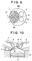
- FIGURE 10 is a schematic longitudinal sectional view, illustrating a seventh embodiment of the direct-fuel-injection-type spark-ignition internal combustion engine of the invention.
- the same reference numerals as those used for the foregoing embodiments represent the same component elements. Differences from the first embodiment will be mainly described.
- a cavity 8' is formed so that a side wall of the cavity 8' on the side of a fuel injection valve 7 and a side wall on the side of a fuel guide portion have lower heights than a side wall on the side of an ignition plug 6.
- Fuel injected from a slit-like pore of the fuel injection valve 7 forms a sector-shaped fuel spray having a small thickness.
- the thickness of the fuel spray gradually increases with increases in the travel distance of the spray and with increases in the moving distance thereof after the impact on the side wall. Therefore, in order to prevent fuel from flowing out of the cavity 8', the height of the side wall near the ignition plug 6 must be relatively large.
- the area of the inner surfaces of the cavity increases and, therefore, the area in the cavity that receives heat during combustion increases, so that heat loss increases. As shown in FIG. 10, however, the heat-receiving area in the cavity 8' is decreased, so that heat loss is reduced. It should also be appreciated that the heat-receiving areas of the cavities shown in FIGS. 1-10 may also be decreased, so that heat loss is reduced.
- the shape of the cavity is set so that at least a portion of the fuel guide portion is adjacent to the cylinder-side opening of an intake port, in order to achieve a good uniform combustion based on fuel injection performed during the intake stroke.
- the side wall of the cavity may extend around only the ignition plug and the cylinder-side opening of an exhaust port.
- the fuel injection valve injects fuel in the shape of a sector having a small thickness.
- fuel may also be injected in the shape of a cone or a cylinder, for example.
- whatever shape of the fuel spray is selected it is essential to select or adjust a shape of the fuel spray so that the whole or most of the injected fuel will be prevented from flowing out of the cavity, taking into consideration the expansion of the fuel spray in the direction of height in accordance with the travel distance of the fuel spray and the moving distance thereof after the impact on the cavity side wall, as mentioned above in conjunction with FIG. 10. Therefore, a fuel injection valve that has a plurality of small injection holes to inject fuel in the form of a plurality of narrow cylinders is particularly useful, compared with the fuel injection valves employed FIGS. 1-10.
- the fuel injection valve is disposed in the cavity side wall
- the disposal of the fuel injection is not particularly limited, as long as the fuel injecting direction and the cavity shape are set so that most of the fuel injected is prevented from flowing out of the cavity, as stated above.
- the fuel injection valve may be disposed outside the cavity.
- a direct-fuel-injection-type spark-ignition internal combustion engine has an ignition plug (6), a cavity (8) formed in an upper wall of a cylinder (10), a fuel injection valve (7) that injects fuel so that most of the fuel strikes a side wall (8b) of the cavity (8) at an acute angle with respect to a tangent to the side wall at the point where the fuel strikes it, and a fuel guide portion that is provided in the side wall (8b) of the cavity (8) and that guides most of the fuel to the vicinity of the ignition plug (6).
- the direct-fuel-injection-type spark-ignition internal combustion engine is able to realize a good stratified charge combustion by reliably positioning a major portion of combustible mixture in the vicinity of the ignition plug at the time of ignition.
Landscapes
- Engineering & Computer Science (AREA)
- Chemical & Material Sciences (AREA)
- Combustion & Propulsion (AREA)
- Mechanical Engineering (AREA)
- General Engineering & Computer Science (AREA)
- Combustion Methods Of Internal-Combustion Engines (AREA)
- Fuel-Injection Apparatus (AREA)
Abstract
Description
Claims (12)
- A direct-fuel-injection-type spark-ignition internal combustion engine characterized by comprising:a cylinder (10) in which a fuel is combusted;an ignition plug (6) that ignites the fuel in the cylinder (10);a cavity (8) that is formed in an upper wall of the cylinder (10) and that has a side wall (8b) surrounding the ignition plug (6);a fuel injection valve (7) that injects the fuel so that a main portion of the fuel strikes the side wall (8b) of the cavity (8) at an acute angle with respect to a tangent to the side wall at the point where the fuel strikes the side wall (8b); anda fuel guide portion (8b) that is provided in the side wall (8b) of the cavity (8) and that guides the fuel that has struck the side wall (8b) to a vicinity of the ignition plug (6).
- A direct-fuel-injection-type spark-ignition internal combustion engine according to claim 1, characterized in that:the fuel injection valve (7) injects the main portion of the fuel separately in at least two directions, and portions of the main portion of the fuel injected in the two directions are guided along the fuel guide portion (8b) to the vicinity of the ignition plug (7) so as to face each other.
- A direct-fuel-injection-type spark-ignition internal combustion engine according to claim 1, characterized in that:at least a portion of the fuel guide portion (8b) is adjacent to an intake port opening (1) formed in the upper wall of the cylinder (10).
- A direct-fuel-injection-type spark-ignition internal combustion engine according to claim 1, characterized in that:at least a portion of the fuel guide portion (8b) is adjacent to an exhaust port opening (2) formed in the upper wall of the cylinder (10).
- A direct-fuel-injection-type spark-ignition internal combustion engine according to claim 1, characterized by further comprising:a barrier portion (18b') provided in the fuel guide portion (8b) so that a liquid fuel moving along the fuel guide portion (8b) strikes the barrier portion (18b') in the vicinity of the ignition plug (6).
- A direct-fuel-injection-type spark-ignition internal combustion engine according to claim 1, characterized in that:the fuel injection valve (7) injects the fuel as a generally flat sector-shaped fuel spray having a small thickness so that a central portion of the sector-shaped fuel spray in a direction of a width of the sector-shaped fuel spray is directed substantially toward a center axis of the ignition plug (6).
- A direct-fuel-injection-type spark-ignition internal combustion engine according to claim 1, characterized by further comprising:a pocket portion (18c) that is provided in the side wall of the cavity (8) and that has a wall surface surrounding a portion of a periphery of the ignition plug (6) and opens inwardly with respect to the cavity (8), the wall surface of the pocket portion (18c) extending from the fuel guide portion (8b).
- A direct-fuel-injection-type spark-ignition internal combustion engine according to claim 7, characterized in that:a portion of the side wall of the cavity (8) extending further from the fuel guide portion (8b) is formed so that an imaginary surface extending from the fuel guide portion intersects the wall surface of the pocket portion (18c).
- A direct-fuel-injection-type spark-ignition internal combustion engine according to claim 1, characterized in that:the side wall of the cavity (8) is formed so that a portion of the side wall on a side of the ignition plug (6) is higher than a portion of the side wall on a side of the fuel injection valve (7).
- A direct-fuel-injection-type spark-ignition internal combustion engine according to claim 1, characterized in that:the side wall of the cavity (8) extends around at least one of an intake port opening (1) and an exhaust port opening (2) that are formed in the upper wall of the cylinder (10).
- A direct-fuel-injection-type spark-ignition internal combustion engine according to claim 10, characterized in that:the fuel injection valve (7) injects the fuel so that the fuel moves across at least one of the intake port opening (1) and the exhaust port opening (2) around which the side wall of the cavity (8) extends.
- A method of injecting fuel in a direct-fuel-injection-type spark-ignition internal combustion engine having a cylinder (10) in which a fuel is combusted; an ignition plug (6) that ignites the fuel in the cylinder (10); and a cavity (8) that is formed in an upper wall of the cylinder (10) and that has a side wall surrounding the ignition plug (6); the method comprising:injecting fuel with a fuel injection valve (7) so that a main portion of the fuel strikes the side wall of the cavity (8) at an acute angle with respect to a tangent to the side wall at the point where the fuel strikes the wide wall (8b); andguiding the fuel that has struck the side wall (8b) to a vicinity of the ignition plug (6) with a fuel guide portion (8b) that is provided in the side wall of the cavity (8).
Applications Claiming Priority (2)
| Application Number | Priority Date | Filing Date | Title |
|---|---|---|---|
| JP23595899 | 1999-08-23 | ||
| JP23595899A JP3633392B2 (en) | 1999-08-23 | 1999-08-23 | In-cylinder injection spark ignition internal combustion engine |
Publications (3)
| Publication Number | Publication Date |
|---|---|
| EP1079081A2 true EP1079081A2 (en) | 2001-02-28 |
| EP1079081A3 EP1079081A3 (en) | 2001-10-10 |
| EP1079081B1 EP1079081B1 (en) | 2003-05-07 |
Family
ID=16993744
Family Applications (1)
| Application Number | Title | Priority Date | Filing Date |
|---|---|---|---|
| EP00118020A Expired - Lifetime EP1079081B1 (en) | 1999-08-23 | 2000-08-22 | Direct-fuel-injection-type spark-ignition internal combustion engine and method of fuel injection |
Country Status (4)
| Country | Link |
|---|---|
| US (1) | US6363909B1 (en) |
| EP (1) | EP1079081B1 (en) |
| JP (1) | JP3633392B2 (en) |
| DE (1) | DE60002533T2 (en) |
Cited By (2)
| Publication number | Priority date | Publication date | Assignee | Title |
|---|---|---|---|---|
| FR2853355A1 (en) * | 2003-04-04 | 2004-10-08 | Peugeot Citroen Automobiles Sa | Internal combustion engine e.g. two-stroke engine, has petrol jet and lower face of cylinder head that are conformed such that part of injected petrol in combustion chamber strikes lower face of cylinder head |
| EP2166210A4 (en) * | 2007-06-29 | 2010-08-11 | Mitsubishi Motors Corp | INJECTION TYPE INTERNAL COMBUSTION ENGINE IN THE CYLINDER |
Families Citing this family (7)
| Publication number | Priority date | Publication date | Assignee | Title |
|---|---|---|---|---|
| DE10026323A1 (en) * | 2000-05-26 | 2001-11-29 | Bosch Gmbh Robert | Fuel injection system |
| JP2002089267A (en) * | 2000-09-19 | 2002-03-27 | Honda Motor Co Ltd | Gasoline direct injection engine |
| JP3722285B2 (en) * | 2002-02-28 | 2005-11-30 | ヤマハ発動機株式会社 | In-cylinder fuel injection internal combustion engine |
| SE0200792D0 (en) * | 2002-03-18 | 2002-03-18 | Saab Marine Electronics | Horn Antenna |
| EP1413745B1 (en) * | 2002-10-22 | 2012-02-22 | Ford Global Technologies, LLC | Fuel injector and a direct injected combustion engine |
| JP4415843B2 (en) * | 2004-12-10 | 2010-02-17 | トヨタ自動車株式会社 | Internal combustion engine |
| JP5909307B1 (en) * | 2015-12-26 | 2016-04-26 | 康仁 矢尾板 | Engine with improved knock resistance |
Family Cites Families (9)
| Publication number | Priority date | Publication date | Assignee | Title |
|---|---|---|---|---|
| US3572298A (en) * | 1968-01-08 | 1971-03-23 | Shigeru Onishi | Stratified charge engine |
| DE2411080A1 (en) * | 1974-03-08 | 1975-09-18 | Volkswagenwerk Ag | EXTERNAL IGNITION ENGINE OPERATED WITH LOAD STRATIFICATION |
| JPS5950848B2 (en) | 1978-05-11 | 1984-12-11 | トヨタ自動車株式会社 | Fuel injection valve for internal combustion engine with pre-chamber |
| AT378824B (en) | 1980-12-18 | 1985-10-10 | List Hans | INTERNAL COMBUSTION ENGINE WITH FUEL INJECTION AND FORD IGNITION |
| JPS60261922A (en) | 1984-06-07 | 1985-12-25 | Sanshin Ind Co Ltd | Internal-combustion engine of in-cylinder injection type |
| JPS62214216A (en) * | 1986-03-14 | 1987-09-21 | Isuzu Motors Ltd | Combustion chamber of internal combustion engine |
| US5042442A (en) * | 1990-04-10 | 1991-08-27 | Hale Fire Pump Company | Internal combustion engine |
| US5605125A (en) | 1994-11-18 | 1997-02-25 | Yaoita; Yasuhito | Direct fuel injection stratified charge engine |
| JPH08177497A (en) | 1994-12-20 | 1996-07-09 | Nissan Motor Co Ltd | Direct injection spark ignition internal combustion engine |
-
1999
- 1999-08-23 JP JP23595899A patent/JP3633392B2/en not_active Expired - Fee Related
-
2000
- 2000-08-07 US US09/634,877 patent/US6363909B1/en not_active Expired - Fee Related
- 2000-08-22 DE DE60002533T patent/DE60002533T2/en not_active Expired - Fee Related
- 2000-08-22 EP EP00118020A patent/EP1079081B1/en not_active Expired - Lifetime
Cited By (3)
| Publication number | Priority date | Publication date | Assignee | Title |
|---|---|---|---|---|
| FR2853355A1 (en) * | 2003-04-04 | 2004-10-08 | Peugeot Citroen Automobiles Sa | Internal combustion engine e.g. two-stroke engine, has petrol jet and lower face of cylinder head that are conformed such that part of injected petrol in combustion chamber strikes lower face of cylinder head |
| EP2166210A4 (en) * | 2007-06-29 | 2010-08-11 | Mitsubishi Motors Corp | INJECTION TYPE INTERNAL COMBUSTION ENGINE IN THE CYLINDER |
| US8448624B2 (en) | 2007-06-29 | 2013-05-28 | Mitsubishi Jidosha Kogyo Kabushiki Kaisha | Direct injection internal combustion engine |
Also Published As
| Publication number | Publication date |
|---|---|
| JP3633392B2 (en) | 2005-03-30 |
| DE60002533D1 (en) | 2003-06-12 |
| DE60002533T2 (en) | 2004-03-18 |
| EP1079081B1 (en) | 2003-05-07 |
| JP2001059423A (en) | 2001-03-06 |
| US6363909B1 (en) | 2002-04-02 |
| EP1079081A3 (en) | 2001-10-10 |
Similar Documents
| Publication | Publication Date | Title |
|---|---|---|
| EP1006266B1 (en) | Direct fuel injection-type spark ignition internal combustion engine | |
| CN1325777C (en) | Incylinder direct injection spark ignition engine | |
| US5720253A (en) | Direct-injection type spark-ignition internal combustion engine | |
| EP0839997B1 (en) | Combustion chamber structure having piston cavity | |
| EP0971108B1 (en) | Direct cylinder injection-type spark ignition internal combustion engine | |
| EP1069291B1 (en) | In-cylinder direct-injection spark-ignition engine | |
| US5915353A (en) | Cylinder direct injection spark-ignition engine | |
| US6799550B2 (en) | Spark-ignition engine having direct fuel injection | |
| US6684848B2 (en) | Direct-injection spark-ignition engine | |
| EP1079081B1 (en) | Direct-fuel-injection-type spark-ignition internal combustion engine and method of fuel injection | |
| US6269790B1 (en) | Combustion chamber for DISI engines with exhaust side piston bowl | |
| EP0971109B1 (en) | Direct cylinder injection-type spark ignition internal combustion engine | |
| EP1043484B1 (en) | Direct fuel injection-type spark-ignition internal combustion engine | |
| EP1041258B1 (en) | Direct fuel injection-type spark-ignition internal combustion engine | |
| JP4115549B2 (en) | Direct-injection spark ignition internal combustion engine | |
| EP1041257A2 (en) | Direct fuel injection-type spark-ignition internal combustion engine | |
| JP3838346B2 (en) | In-cylinder injection spark ignition internal combustion engine | |
| JP3573138B2 (en) | In-cylinder injection spark ignition internal combustion engine | |
| JP3861825B2 (en) | Direct-injection spark ignition internal combustion engine | |
| JP2000282864A (en) | Combustion chamber structure of in-cylinder injection engine | |
| JPH03105017A (en) | Direct injection type internal combustion engine using outside ignition | |
| JPH01280627A (en) | Combustion chamber structure for two cycle internal combustion engine |
Legal Events
| Date | Code | Title | Description |
|---|---|---|---|
| PUAI | Public reference made under article 153(3) epc to a published international application that has entered the european phase |
Free format text: ORIGINAL CODE: 0009012 |
|
| 17P | Request for examination filed |
Effective date: 20000822 |
|
| AK | Designated contracting states |
Kind code of ref document: A2 Designated state(s): AT BE CH CY DE DK ES FI FR GB GR IE IT LI LU MC NL PT SE Kind code of ref document: A2 Designated state(s): DE FR GB |
|
| AX | Request for extension of the european patent |
Free format text: AL;LT;LV;MK;RO;SI |
|
| PUAL | Search report despatched |
Free format text: ORIGINAL CODE: 0009013 |
|
| AK | Designated contracting states |
Kind code of ref document: A3 Designated state(s): AT BE CH CY DE DK ES FI FR GB GR IE IT LI LU MC NL PT SE |
|
| AX | Request for extension of the european patent |
Free format text: AL;LT;LV;MK;RO;SI |
|
| RIC1 | Information provided on ipc code assigned before grant |
Free format text: 7F 02B 23/10 A, 7F 02B 19/10 B |
|
| 17Q | First examination report despatched |
Effective date: 20011210 |
|
| AKX | Designation fees paid |
Free format text: DE FR GB |
|
| GRAH | Despatch of communication of intention to grant a patent |
Free format text: ORIGINAL CODE: EPIDOS IGRA |
|
| GRAH | Despatch of communication of intention to grant a patent |
Free format text: ORIGINAL CODE: EPIDOS IGRA |
|
| GRAA | (expected) grant |
Free format text: ORIGINAL CODE: 0009210 |
|
| AK | Designated contracting states |
Designated state(s): DE FR GB |
|
| REG | Reference to a national code |
Ref country code: GB Ref legal event code: FG4D |
|
| REF | Corresponds to: |
Ref document number: 60002533 Country of ref document: DE Date of ref document: 20030612 Kind code of ref document: P |
|
| ET | Fr: translation filed | ||
| PLBE | No opposition filed within time limit |
Free format text: ORIGINAL CODE: 0009261 |
|
| STAA | Information on the status of an ep patent application or granted ep patent |
Free format text: STATUS: NO OPPOSITION FILED WITHIN TIME LIMIT |
|
| 26N | No opposition filed |
Effective date: 20040210 |
|
| PGFP | Annual fee paid to national office [announced via postgrant information from national office to epo] |
Ref country code: DE Payment date: 20070816 Year of fee payment: 8 |
|
| PGFP | Annual fee paid to national office [announced via postgrant information from national office to epo] |
Ref country code: GB Payment date: 20070822 Year of fee payment: 8 |
|
| PGFP | Annual fee paid to national office [announced via postgrant information from national office to epo] |
Ref country code: FR Payment date: 20070808 Year of fee payment: 8 |
|
| GBPC | Gb: european patent ceased through non-payment of renewal fee |
Effective date: 20080822 |
|
| REG | Reference to a national code |
Ref country code: FR Ref legal event code: ST Effective date: 20090430 |
|
| PG25 | Lapsed in a contracting state [announced via postgrant information from national office to epo] |
Ref country code: DE Free format text: LAPSE BECAUSE OF NON-PAYMENT OF DUE FEES Effective date: 20090303 Ref country code: FR Free format text: LAPSE BECAUSE OF NON-PAYMENT OF DUE FEES Effective date: 20080901 |
|
| PG25 | Lapsed in a contracting state [announced via postgrant information from national office to epo] |
Ref country code: GB Free format text: LAPSE BECAUSE OF NON-PAYMENT OF DUE FEES Effective date: 20080822 |