EP1078892A2 - Procédé et four de fusion de verre avec brûleurs d'oxygène-combustible - Google Patents
Procédé et four de fusion de verre avec brûleurs d'oxygène-combustible Download PDFInfo
- Publication number
- EP1078892A2 EP1078892A2 EP00307320A EP00307320A EP1078892A2 EP 1078892 A2 EP1078892 A2 EP 1078892A2 EP 00307320 A EP00307320 A EP 00307320A EP 00307320 A EP00307320 A EP 00307320A EP 1078892 A2 EP1078892 A2 EP 1078892A2
- Authority
- EP
- European Patent Office
- Prior art keywords
- fuel
- flame
- lean
- burner
- oxy
- Prior art date
- Legal status (The legal status is an assumption and is not a legal conclusion. Google has not performed a legal analysis and makes no representation as to the accuracy of the status listed.)
- Withdrawn
Links
Images


Classifications
-
- C—CHEMISTRY; METALLURGY
- C03—GLASS; MINERAL OR SLAG WOOL
- C03B—MANUFACTURE, SHAPING, OR SUPPLEMENTARY PROCESSES
- C03B5/00—Melting in furnaces; Furnaces so far as specially adapted for glass manufacture
- C03B5/16—Special features of the melting process; Auxiliary means specially adapted for glass-melting furnaces
- C03B5/235—Heating the glass
- C03B5/2353—Heating the glass by combustion with pure oxygen or oxygen-enriched air, e.g. using oxy-fuel burners or oxygen lances
-
- Y—GENERAL TAGGING OF NEW TECHNOLOGICAL DEVELOPMENTS; GENERAL TAGGING OF CROSS-SECTIONAL TECHNOLOGIES SPANNING OVER SEVERAL SECTIONS OF THE IPC; TECHNICAL SUBJECTS COVERED BY FORMER USPC CROSS-REFERENCE ART COLLECTIONS [XRACs] AND DIGESTS
- Y02—TECHNOLOGIES OR APPLICATIONS FOR MITIGATION OR ADAPTATION AGAINST CLIMATE CHANGE
- Y02P—CLIMATE CHANGE MITIGATION TECHNOLOGIES IN THE PRODUCTION OR PROCESSING OF GOODS
- Y02P40/00—Technologies relating to the processing of minerals
- Y02P40/50—Glass production, e.g. reusing waste heat during processing or shaping
Definitions
- This invention relates to a method of and furnace for melting glass, and particularly to an improved industrial furnace and burner system used to melt and refine glass.
- regenerative or recuperative heat recovery systems are typically used to preheat the air feed.
- a regenerative heat recovery system pre-heats the air feed by alternately using the hot furnace off-gases to heat refractory and then using this hot refractory to preheat the air feed.
- a recuperative waste heat recovery system achieves the same goal using a shell and tube heat exchanger to transfer heat from the hot furnace gases to the air feed through a metallic tube wall.
- the air-based combustion systems have two major disadvantages.
- the predominate mode for heat transfer with air fired system is conduction from the hot combustion gases to the refractory walls and roof and radiation from the refractory surfaces to the glass melt.
- This heat transfer rate is severely limited by the maximum operating temperature of the furnace refractory, low emissivity of the glass melt, and low thermal conductivity of the glass melt. Bubblers are typically used to somewhat increase the glass melt circulation and increase the effective conductivity of the glass melt.
- electrical resistance heating can be used to significantly increase the glass melting rate with a substantial increase in operating costs.
- the maximum roof temperature and low glass melt emissivity significantly limits the specific glass melting rate, typically measured as tons of glass/ft 2 /day. This low specific melting rate significantly increases the furnace capital cost.
- recuperative and regenerative heat recovery systems are expensive and typically contaminants in the furnace off-gas plug and degrade recuperators and regenerators over time.
- recuperative and regenerative heat recovery systems significantly increase capital and maintenance costs and degrade furnace performance over time.
- Oxy-fuel burners and electrical resistance heating have been used for many years to compensate for the adverse effect of the degradation in productivity of recuperative and regenerative over time.
- Oxy-fuel burners have had two traditional problems. First, the use of substantially pure oxygen increases the furnace operating cost. Second, oxy-fuel burners have a shorter and hotter flame. This shorter and hotter flame can cause localized overheating of refractory in the region of the burner. In addition, the short flame of oxy-fuel burners makes it difficult to heat the glass melt near the center of large furnaces.
- WO-A-99/31021 discloses controlling the velocity of gaseous fuel and oxygen in an oxy-fuel burner mounted in the roof of a glass melting surface for increasing the melting rare of the glass.
- US-A-5,139,558 discloses the use of oxy-fuel burners located on the furnace roof and aimed at the interface between the batch and the melt in order to increase the melting rate of the glass and to prevent batch materials from entering the upstream zone.
- the furnace roof to glass melt distance is often greater than typical oxy-fuel flame length, the thermal efficiency of the process is not adequate for use outside of regenerative or recuperative furnaces.
- US-A-5,346,424 and US-A-5,643,348 attempt to overcome this problem by injecting oxygen and fuel at separate points and producing a large combustion "flame cloud" in the center of the furnace.
- This approach eliminates the oxy-fuel flame length limitation, but suffers from a safety problem. There is no apparent reliable method to heat the fuel and oxidant prior to mixing to maintain reliable ignition of the fuel and oxidant of this process. Premature mixing of the fuel and oxidant could lead to explosions.
- a method of melting glass in a furnace having at least a roof and side-walls comprising the steps of: generating at least one fuel-rich flame using at least one oxy-fuel burner; generating at least one fuel-lean flame using at least one oxy-fuel burner; intersecting said fuel-rich flame with said fuel-lean flame near the surface of the glass to produce a secondary combustion zone having a higher temperature than either the fuel-rich flame or the fuel lean flame.
- the invention also provides a furnace having a roof and side-walls for melting glass comprising: at least one oxy-fuel burner for generating at least one fuel-rich flame; at least one oxy-fuel burner for generating at least one fuel-lean flame; wherein the oxy-fuel burners are orientated such that in use, said at least one fuel-rich flame and said at least one fuel-lean flame are directed to intersect near the surface of the glass.
- the method and apparatus according to the invention enable the amount of heat transferred to the glass (ie the molten glass or the solid glass forming components) while reducing the amount of heat transferred to the roof at side walls of the furnace.
- the interacting fuel-rich and fuel-lean flames generated by the oxy-fuel burners enhance heat transfer to the material to be melted, glass melt or batch, by maximizing the flame area and temperature in contact with the solid batch or liquid melt interface.
- Reaction 2 illustrates the stoichiometry for a fuel-rich flame for use in accordance with the invention.
- Reaction [2] The actual combustion process would contain many more species.
- the CO and H 2 products can be further oxidized to CO 2 and H 2 O to subsequently release additional thermal energy.
- Reaction [2] is intended only to illustrate the overall stoichiometry of this combustion process.
- x and y are the fraction of the carbon and hydrogen, respectively, in the liquid or gaseous fuel that are fully oxidized in the fuel-rich flame.
- x and y would be in the range of 0.1 to 0.8.
- z is fraction of the gaseous or liquid fuel that is used in the fuel-rich flame. The balance of the fuel would be used in the fuel-lean flame.
- both the fuel-rich and fuel-lean flames have a much lower temperatures than conventional O 2 -fuel flames, much less heat is transferred to the burner block and refractory in the region of the burner.
- These fuel-rich and fuel-lean flames are advantageously directed toward a common area near the interface of the batch material or the melt. As the flames interact, combustion can be completed near the batch material or batch/melt interface, which results in higher temperature combustion gases in contact with batch materials or the melt and, therefore, more efficient heat transfer to the batch material or melt.
- axisymmetric burners are placed in the roof of a furnace according to the present invention.
- non-axisymmetric or axisymmetric burners are placed in the side-walls of a furnace according to the present invention.
- curved burners are placed in either the side-wall or roof of a furnace according to the present invention providing a means for altering the combustion intensity profile inside the furnace.
- Advantages of the invention include increased uniformity of the heat distribution at the melt or batch surface, a reduced exposure to heat of the burner assembly resulting from the lower temperature of the flame near the burner, and a lower fuel consumption and a lower oxidant consumption per tonne of melt processed by the furnace.
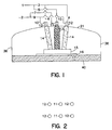
- Figure 1 a diagrammatic elevational representation of one embodiment of a furnace according to the present invention wherein the burners are located in the roof of the furnace.
- Figure 2 is a plan view of the layout of a burner block according to the present invention.
- Figure 3 is a front view of an axisymmetric burner for use in an embodiment of the present invention.
- Figure 4 is a cross-sectional view of the axisymmetric burner of Fig.3 taken through line A-A.
- Figure 5 is a front view of another axisymmetric burner for use in an embodiment of the present invention.
- Figure 6 is a cross-sectional view of the axisymmetric burner of Fig. 5 taken through line A-A.
- Figure 7 is a diagrammatic elevational representation of a second embodiment of a furnace according to the present wherein the burners are located in the side-wall of the present invention.
- Figure 8 is a front view of a non-axisymmetric burner for use in the furnace of Fig. 7.
- Figure 9 is a cross-sectional view of the non-axisymmetric burner of Figure 8 taken through line A-A.
- Figure 10 is a front view of another non-axisymmetric burner for use in the furnace of Fig. 7.
- Figure 11 is a cross-sectional view of the non-axisymmetric burner of Fig. 10.
- Figure 12 is a cross-sectional view of a further embodiment of a furnace according to the present invention wherein the burners are curved.
- This invention advantageously uses the interaction of relatively cool fuel-rich and fuel-lean oxy-fuel flames to produce hotter combustion gases at a position in an industrial furnace that is displaced from the burners and is near the vicinity of the glass forming solids and glass melt. This process efficiency increase with increasing gas temperature and increasing interfacial area between the hot combustion gases.
- This invention advantageously uses axisymmetric and non-axisymmetric burners.
- the axisymmetric burner produces a flame that can more effectively heat at further distances from the burner.
- the non-axisymmetric burner produces a flame that has a larger interfacial area between the batch material and the melt at shorter distances from the burner.
- Roof mounted burners would typically be axisymmetric and furnace wall mounted burners would typically be non-axisymmetric because the roof is a greater distance from the surface of the melt in an industrial furnace.
- side wall mounted axisymmetric burners or a combination of axisymmetric and non-axisymmetric burners can be used.
- Figure 1 illustrates the use of this invention with axisymmetric roof burners 11 and 12 placed in the roof (crown) 21 of an industrial furnace also having side walls 36 and a bottom 40.
- the hydrocarbon fuel feed 1 would typically be used with either a gaseous or liquid hydrocarbon fuel. Natural gas, predominately methane, is the most common gaseous fuel.
- Liquid hydrocarbon fuels have values of (a) in reaction [1] greater than four.
- Fuel oils are the most common liquid hydrocarbon fuel used in industrial furnaces and would have values of (a) in reactions [1] or [2] of greater than 10 and H/C, or b/a ratio, between 2 and 1.
- This invention preferably uses a substantially pure oxygen feed 2.
- Substantially pure oxygen preferably has an O 2 concentration greater than 70 volume (or molar) percent and more preferably greater than 90 percent.
- the overall hydrocarbon fuel feed 1 and oxygen feed 2 are adjusted such that the value of c in Reactions [1] or [2] is greater than 0.7 and less than 1.3. More preferably the value of c is between 0.9 and 1.2.
- the hydrocarbon fuel feed 1 is divided into a hydrocarbon fuel feed 5 for production of the fuel-rich flames 13 by fuel-rich burner 11 and a hydrocarbon fuel feed 3 for production of fuel-lean flames 14 by fuel-lean burners 12. If there are multiple fuel-rich flames 13, then the hydrocarbon fuel feed 5 of the fuel-rich flames 13 would be further divided into additional hydrocarbon fuel feeds for each individual fuel-rich burners 11.
- the ratio of the hydrocarbon stream in hydrocarbon fuel feed 5 to the hydrocarbon stream in hydrocarbon fuel feed 1 is the value of z in Reactions [1] or [2].
- the balance of the fuel (1-z) is fed via hydrocarbon fuel feed 3 to the fuel-lean burners 12.
- the substantially pure oxygen feed 2 is divided into an oxygen feed 7 for the fuel-rich burner 11 and an oxygen feed 9 for the fuel-lean burner 12.
- more than one fuel-lean flame 14 would be used in conjunction with each fuel-rich flame 13.
- both the hydrocarbon fuel feed 3 and substantially pure oxygen feed 9 would be divided into hydrocarbon fuel feeds 4 and substantially pure oxygen feeds 10 for the fuel-lean burners 12 that produce the fuel-lean flames 14.
- the overall gas flow rate for each fuel-lean flame 14 and fuel-rich fame 13 are roughly equal.
- the velocity of the combustion gases of the fuel-rich flames 13 and the fuel-lean flame 14 should be between 150 and 500 feet per second at the exit of the burner block 20.
- the relative flow rates of the hydrocarbon fuel feeds 4 and substantially pure oxygen feed 10 for the fuel-lean burners 12 to produce a fuel-lean flame 14 and the hydrocarbon fuel feed 5 and substantially pure oxygen feed 7for the fuel-rich burner 11 for producing a fuel-rich flame 13 are adjusted to the minimum adiabatic flame temperature that provides a stable flame.
- the adiabatic flame temperature for the fuel-rich flame 13 and fuel-lean flames 14 should be greater than 800°C and less than 2000°C, preferably greater than 1000°C and less than 1600°C.
- the adiabatic flame temperature of the fuel-rich flame 13 and fuel-lean flames 14 are estimated using standard methods in the example.
- the calculated temperature of fuel-rich flame 13 and fuel-lean flames 14 can be adjusted to the desired values by adjusting the values of x, y, and z accordingly.
- the lower values of x and y, with constant adiabatic flame temperature, may be advantageously used by preheating the gaseous hydrocarbon fuel feed 1 and/or the oxidant fuel feed 2.
- the values of x, y, and z determine both the fuel to oxidant feed rates for the fuel-lean burner 12 and the fuel to oxidant feed ratio for the fuel-rich burner 11.
- the absolute values of the these flow rates are set by the desired total thermal heat output of the assembly of fuel-rich and fuel-lean burners.
- the distance between the fuel-rich 11 and fuel-lean 12 burners and the batch 16 or the top surface of the melt 17 is typically between 4 and 12 feet.
- the velocity of the combustion gases of the fuel-rich flames 13 and the fuel-lean flame 14 should be between 150 and 500 feet per second at the exit of the fuel-rich burners 11 and fuel-lean burners 12.
- the burner to batch/melt distance and nature of the melt surface determine the optimum combustion gas velocity. The required velocity increases with increasing burner to batch/melt distance. The burner velocity is limited by entrainment of solid particles.
- Fuel-rich flame 13 and fuel-lean flames 14 are directed toward a high temperature secondary combustion zone 15 in the vicinity of the upper surface of the melt 17. This objective can be accomplished by directing the fuel-rich flame 13 and fuel-lean flame 14 to intersect above the melt 17 so that hot gases from the secondary combustion zone 15 flow to the surface of the melt 17.
- Figure 2 depicts the arrangement of a set of fuel-rich burners 11 and a set of fuel-lean burners 12 according to an embodiment of the present invention in which six burners are placed in the roof of furnace such as that depicted in Figure 1.
- a fuel-lean burner 12 is placed on each side of a fuel-rich burner 11.
- FIGs 3, 4, 5 and 6 illustrate the key components of the gaseous hydrocarbon fuel and liquid hydrocarbon fuel axisymmetric fuel-rich burners 11 and fuel-lean burners 12 respectively.
- the gas hydrocarbon fuel axisymmetric fuel-rich burner 11 or fuel-lean burner 12 consists of a cylindrical metallic or ceramic gaseous fuel passage 18, an annular substantially pure oxygen passage 19 and a burner block 20.
- the gaseous fuel passage 18 is advantageously retracted into the burner block 20.
- the burner block 20 may be mounted flush with the furnace crown 21, as shown on Figure 1, or protruding into the furnace from the crown or roof 21. Alternatively, oxygen may be fed through the central pipe 18 and fuel fed through annulus 19.
- the axisymmetric liquid hydrocarbon fuel-rich burner 11 or fuel-lean burner 12 depicted in Figures 5 and 6 is very similar to the gaseous fuel burner of Figures 3 and 4.
- the liquid fuel passage 23 and liquid atomizer 24 is substituted for the gaseous fuel passage 18.
- the liquid fuel atomizer 24 could use only liquid hydrocarbon fuel pressure or gas, preferably substantially pure O 2 to assist atomization.
- the atomized liquid fuel and substantially pure O 2 are mixed to produce a flame 22 that can be either a fuel-rich flame 13 or a fuel lean flame 14.
- Figure 7 illustrates another embodiment of the present invention in which non-axisymmetric fuel-lean burners 28 and 32 and fuel-rich burner 30 are mounted in side wall 36 to enhance the glass melting process.
- the specifications for the hydrocarbon fuel feed 25 and substantially pure oxygen feed 26 for the non-axisymmetric fuel-rich burner 30 and fuel-lean burners 28 and 32 are identical to the specifications for the hydrocarbon fuel feed 1 and substantially pure oxygen feed 2 for the axisymmetric burner 11 or 12.
- the flow rates of the upper non-axisymmetric fuel-lean flame 37 and the non-axisymmetric fuel-rich flame 38 should be roughly equal.
- the flow rate and velocity of the lower non-axisymmetric fuel-lean flame 39 can advantageously be relatively higher to help direct the flame toward the batch 16 and the surface of the melt 17.
- the velocity of the non-axisymmetric flames should be between 40 and 200 feet per second at the exit of the burner block 44.
- the adiabatic flame temperature of the fuel-rich flame 38 and the fuel-lean flames 37 or 39 should be between 800°C and 2000°C, more preferably between 1000°C and 1600°C.
- Fuel-lean burner 32 produces a substantially horizontal fuel-lean flame 39 while fuel-rich burner 30 and fuel-lean burner 32 produce angled fuel-rich flame 38 and fuel-lean flame 37 respectively. All three flames 37, 38, and 39 intersect in combustion zone 41 in the vicinity of the batch 16 or melt 17.
- the angles between the axis of the upper fuel lean flame 37 and the fuel-rich flame 38, relative to the axis of the lower fuel-lean flame 39 is adjusted such that the flame intersect at roughly a common point and the resulting intensification zone 41 in the region of the glass.
- the position of this flame intersection is adjusted to provide the desired heat transfer distribution, which is primarily a function of the furnace dimensions and values of x, y and z.
- FIG. 8 and 9 and Figures 10 and 11 depict the gaseous non-axisymmetric and liquid non-axisymmetric burners 28, 30 and 32.
- the non-axisymmetric burner 28, 30, or 32 has a gaseous fuel passage 42 having an elliptical cross section, and a substantially pure oxygen passage 43 also having an elliptical cross section and a burner block 44.
- the gaseous fuel passage 43 is advantageously retracted into the burner block 44.
- the burner block may be mounted flush with the side-wall 36 or protruding into the furnace from the side-wall 36 as depicted in Figure 7.
- Each of the axisymmetric liquid hydrocarbon fuel burners 28, 30 and 32 in Figure 7 may take the form depicted in Figures 10 and 11 and are very similar to the gaseous fuel burner of Figures 8 and 9.
- the liquid fuel passage 45 and liquid atomizer 46 are substituted for the gaseous fuel passage 42 and substantially pure oxygen passage 47 replaces oxygen passage 43.
- the liquid fuel atomizer 46 could use only liquid hydrocarbon fuel pressure or gas, preferably substantially pure O 2, to assist atomization.
- FIG 12 depicts a cross sectional view of a further embodiment of a burner block for use in the present invention.
- a curved fuel-lean burner 52 in crown 21 produces an arcing fuel-lean flame 54 which interacts in combustion zone 56 in the vicinity of melt 17 (or batch 16, not shown in Figure 12) with arcing fuel-rich flame 55 which is produced by curved fuel-lean burner 53.
- Curved burners 52 and 53 are mounted in crown 21 using mounting bracket 60 held to crown 21 by mounting bolts 61.
- a handle (not shown) can be mounted on the exterior of the burner 52 or 53.
- the curved burner 52 or 53 can be used in various configurations other than being opposed from another curved burner as depicted in Figure 12.
- a straight fuel-rich burner could be interposed between two curved fuel-lean burners directed to have their respective flames intersect near the batch or melt.
- one substantially straight fuel-rich burner could be surrounded by a multiplicity of curved burners which are all directed to have their respective flames intersect near the batch or melt.
Landscapes
- Chemical & Material Sciences (AREA)
- Engineering & Computer Science (AREA)
- Combustion & Propulsion (AREA)
- Materials Engineering (AREA)
- Organic Chemistry (AREA)
- Glass Melting And Manufacturing (AREA)
Applications Claiming Priority (2)
| Application Number | Priority Date | Filing Date | Title |
|---|---|---|---|
| US384065 | 1999-08-26 | ||
| US09/384,065 US6354110B1 (en) | 1999-08-26 | 1999-08-26 | Enhanced heat transfer through controlled interaction of separate fuel-rich and fuel-lean flames in glass furnaces |
Publications (2)
| Publication Number | Publication Date |
|---|---|
| EP1078892A2 true EP1078892A2 (fr) | 2001-02-28 |
| EP1078892A3 EP1078892A3 (fr) | 2003-02-05 |
Family
ID=23515891
Family Applications (1)
| Application Number | Title | Priority Date | Filing Date |
|---|---|---|---|
| EP00307320A Withdrawn EP1078892A3 (fr) | 1999-08-26 | 2000-08-24 | Procédé et four de fusion de verre avec brûleurs d'oxygène-combustible |
Country Status (2)
| Country | Link |
|---|---|
| US (1) | US6354110B1 (fr) |
| EP (1) | EP1078892A3 (fr) |
Cited By (3)
| Publication number | Priority date | Publication date | Assignee | Title |
|---|---|---|---|---|
| EP1236691A2 (fr) * | 2001-03-02 | 2002-09-04 | The Boc Group, Inc. | Procédé et appareil pour la fusion de verre utilsant de brûleurs à l'oxygène-carburant montés dans la voûte |
| US6705118B2 (en) | 1999-08-16 | 2004-03-16 | The Boc Group, Inc. | Method of boosting a glass melting furnace using a roof mounted oxygen-fuel burner |
| US7168269B2 (en) | 1999-08-16 | 2007-01-30 | The Boc Group, Inc. | Gas injection for glass melting furnace to reduce refractory degradation |
Families Citing this family (8)
| Publication number | Priority date | Publication date | Assignee | Title |
|---|---|---|---|---|
| US6722161B2 (en) | 2001-05-03 | 2004-04-20 | The Boc Group, Inc. | Rapid glass melting or premelting |
| FR2880410B1 (fr) * | 2005-01-03 | 2007-03-16 | Air Liquide | Procede de combustion etagee produisant des flammes asymetriques |
| FR2892497B1 (fr) * | 2005-10-24 | 2008-07-04 | Air Liquide | Procede de combustion mixte dans un four a regenerateurs |
| US20100159409A1 (en) * | 2006-06-05 | 2010-06-24 | Richardson Andrew P | Non-centric oxy-fuel burner for glass melting systems |
| US20070281264A1 (en) * | 2006-06-05 | 2007-12-06 | Neil Simpson | Non-centric oxy-fuel burner for glass melting systems |
| JP2010230257A (ja) * | 2009-03-27 | 2010-10-14 | Dainichi Co Ltd | 燃焼装置 |
| US20100242545A1 (en) * | 2009-03-30 | 2010-09-30 | Richardson Andrew P | Cyclical stoichiometric variation of oxy-fuel burners in glass furnaces |
| US20110011134A1 (en) * | 2009-07-15 | 2011-01-20 | Richardson Andrew P | Injector for hydrogen and oxygen bubbling in glass baths |
Citations (6)
| Publication number | Priority date | Publication date | Assignee | Title |
|---|---|---|---|---|
| US4874311A (en) * | 1987-08-03 | 1989-10-17 | American Combustion, Inc. | Method and apparatus for improved regenerative furnace |
| EP0447300A1 (fr) * | 1990-03-16 | 1991-09-18 | L'air Liquide, Societe Anonyme Pour L'etude Et L'exploitation Des Procedes Georges Claude | Procédé de fusion et d'affinage d'une charge |
| EP0601274A1 (fr) * | 1992-12-08 | 1994-06-15 | Praxair Technology, Inc. | Procédé hybride de combustion oxydante |
| EP0877203A1 (fr) * | 1997-05-08 | 1998-11-11 | Praxair Technology, Inc. | Système à combustion avec oxydants doubles |
| WO1999031021A1 (fr) * | 1997-12-17 | 1999-06-24 | Owens Corning | Bruleur d'oxygene-combustible monte dans le plafond d'un four de fusion du verre et procede d'utilisation dudit bruleur |
| EP0939059A2 (fr) * | 1998-02-26 | 1999-09-01 | L'air Liquide, Societe Anonyme Pour L'etude Et L'exploitation Des Procedes Georges Claude | Combustion d'oxygène-carburant pour réduire des émissions NOx dans des fours à haute température |
Family Cites Families (8)
| Publication number | Priority date | Publication date | Assignee | Title |
|---|---|---|---|---|
| US3592623A (en) * | 1969-04-04 | 1971-07-13 | Air Reduction | Glass melting furnace and method of operating it |
| US4473388A (en) * | 1983-02-04 | 1984-09-25 | Union Carbide Corporation | Process for melting glass |
| FR2546155B1 (fr) * | 1983-05-20 | 1986-06-27 | Air Liquide | Procede et installation d'elaboration de verre |
| US4911744A (en) * | 1987-07-09 | 1990-03-27 | Aga A.B. | Methods and apparatus for enhancing combustion and operational efficiency in a glass melting furnace |
| US5139558A (en) | 1991-11-20 | 1992-08-18 | Union Carbide Industrial Gases Technology Corporation | Roof-mounted auxiliary oxygen-fired burner in glass melting furnace |
| US5346524A (en) | 1992-09-14 | 1994-09-13 | Schuller International, Inc. | Oxygen/fuel firing of furnaces with massive, low velocity, turbulent flames |
| US5643348A (en) | 1992-09-14 | 1997-07-01 | Schuller International, Inc. | Oxygen/fuel fired furnaces having massive, low velocity, turbulent flame clouds |
| US5387100A (en) | 1994-02-17 | 1995-02-07 | Praxair Technology, Inc. | Super off-stoichiometric combustion method |
-
1999
- 1999-08-26 US US09/384,065 patent/US6354110B1/en not_active Expired - Fee Related
-
2000
- 2000-08-24 EP EP00307320A patent/EP1078892A3/fr not_active Withdrawn
Patent Citations (6)
| Publication number | Priority date | Publication date | Assignee | Title |
|---|---|---|---|---|
| US4874311A (en) * | 1987-08-03 | 1989-10-17 | American Combustion, Inc. | Method and apparatus for improved regenerative furnace |
| EP0447300A1 (fr) * | 1990-03-16 | 1991-09-18 | L'air Liquide, Societe Anonyme Pour L'etude Et L'exploitation Des Procedes Georges Claude | Procédé de fusion et d'affinage d'une charge |
| EP0601274A1 (fr) * | 1992-12-08 | 1994-06-15 | Praxair Technology, Inc. | Procédé hybride de combustion oxydante |
| EP0877203A1 (fr) * | 1997-05-08 | 1998-11-11 | Praxair Technology, Inc. | Système à combustion avec oxydants doubles |
| WO1999031021A1 (fr) * | 1997-12-17 | 1999-06-24 | Owens Corning | Bruleur d'oxygene-combustible monte dans le plafond d'un four de fusion du verre et procede d'utilisation dudit bruleur |
| EP0939059A2 (fr) * | 1998-02-26 | 1999-09-01 | L'air Liquide, Societe Anonyme Pour L'etude Et L'exploitation Des Procedes Georges Claude | Combustion d'oxygène-carburant pour réduire des émissions NOx dans des fours à haute température |
Cited By (9)
| Publication number | Priority date | Publication date | Assignee | Title |
|---|---|---|---|---|
| US6705118B2 (en) | 1999-08-16 | 2004-03-16 | The Boc Group, Inc. | Method of boosting a glass melting furnace using a roof mounted oxygen-fuel burner |
| US6705117B2 (en) | 1999-08-16 | 2004-03-16 | The Boc Group, Inc. | Method of heating a glass melting furnace using a roof mounted, staged combustion oxygen-fuel burner |
| US7168269B2 (en) | 1999-08-16 | 2007-01-30 | The Boc Group, Inc. | Gas injection for glass melting furnace to reduce refractory degradation |
| US7669439B2 (en) | 1999-08-16 | 2010-03-02 | Linde Llc | Gas injection for glass melting furnace to reduce refractory degradation |
| EP1236691A2 (fr) * | 2001-03-02 | 2002-09-04 | The Boc Group, Inc. | Procédé et appareil pour la fusion de verre utilsant de brûleurs à l'oxygène-carburant montés dans la voûte |
| JP2002356331A (ja) * | 2001-03-02 | 2002-12-13 | Boc Group Inc:The | 天井取付型階段状燃焼酸素バーナーを有するガラス溶融炉を加熱する方法 |
| EP1236691A3 (fr) * | 2001-03-02 | 2003-02-05 | The Boc Group, Inc. | Procédé et appareil pour la fusion de verre utilsant de brûleurs à l'oxygène-carburant montés dans la voûte |
| KR100847950B1 (ko) * | 2001-03-02 | 2008-07-22 | 더 비오씨 그룹 인코포레이티드 | 유리 형성 재료 용융 방법 및 산소-연료 버너 |
| CZ302602B6 (cs) * | 2001-03-02 | 2011-08-03 | The Boc Group, Inc. | Zpusob vytápení tavicí sklárské pece pri použití odstupnovaného kyslíko-palivového horáku ve strope pece |
Also Published As
| Publication number | Publication date |
|---|---|
| US6354110B1 (en) | 2002-03-12 |
| EP1078892A3 (fr) | 2003-02-05 |
Similar Documents
| Publication | Publication Date | Title |
|---|---|---|
| US6237369B1 (en) | Roof-mounted oxygen-fuel burner for a glass melting furnace and process of using the oxygen-fuel burner | |
| JP3981286B2 (ja) | 天井取付型段階的燃焼酸素バーナーを有するガラス溶融炉を加熱する方法 | |
| CA2315486C (fr) | Surpresseur de four de fusion du verre qui utilise un bruleur a oxygene liquide monte sur le toit | |
| EP1850067B1 (fr) | Ensemble brûleur à très failble taux d'émission de NOx | |
| US5853448A (en) | Method of heating the charge of a glass furnace | |
| EP1138638B1 (fr) | Brûleur et procédé de combustion | |
| KR100297031B1 (ko) | 직화로에서알루미늄장입물을용융시키는방법 | |
| US4631080A (en) | Method and apparatus for the heat processing of glass and glass forming material | |
| US6354110B1 (en) | Enhanced heat transfer through controlled interaction of separate fuel-rich and fuel-lean flames in glass furnaces | |
| US20210009457A1 (en) | Multi-chamber submerged combustion melter and system | |
| US4553997A (en) | Process for melting glass in a toroidal vortex reactor | |
| US4617046A (en) | Method for the heat processing of glass and glass forming material | |
| US4617042A (en) | Method for the heat processing of glass and glass forming material | |
| US6652271B2 (en) | Combustion in a porous wall furnace | |
| EP0421490B1 (fr) | Procédé pour la production de verre fondu |
Legal Events
| Date | Code | Title | Description |
|---|---|---|---|
| PUAI | Public reference made under article 153(3) epc to a published international application that has entered the european phase |
Free format text: ORIGINAL CODE: 0009012 |
|
| AK | Designated contracting states |
Kind code of ref document: A2 Designated state(s): AT BE CH CY DE DK ES FI FR GB GR IE IT LI LU MC NL PT SE |
|
| AX | Request for extension of the european patent |
Free format text: AL;LT;LV;MK;RO;SI |
|
| PUAL | Search report despatched |
Free format text: ORIGINAL CODE: 0009013 |
|
| AK | Designated contracting states |
Designated state(s): AT BE CH CY DE DK ES FI FR GB GR IE IT LI LU MC NL PT SE |
|
| AX | Request for extension of the european patent |
Extension state: AL LT LV MK RO SI |
|
| RIC1 | Information provided on ipc code assigned before grant |
Ipc: 7F 23D 14/32 B Ipc: 7F 23C 6/04 B Ipc: 7C 03B 5/235 A |
|
| 17P | Request for examination filed |
Effective date: 20030801 |
|
| AKX | Designation fees paid |
Designated state(s): AT BE CH CY DE DK ES FI FR GB GR IE IT LI LU MC NL PT SE |
|
| GRAP | Despatch of communication of intention to grant a patent |
Free format text: ORIGINAL CODE: EPIDOSNIGR1 |
|
| STAA | Information on the status of an ep patent application or granted ep patent |
Free format text: STATUS: THE APPLICATION IS DEEMED TO BE WITHDRAWN |
|
| 18D | Application deemed to be withdrawn |
Effective date: 20040706 |