EP1078801B1 - Retainerless weather strip - Google Patents
Retainerless weather strip Download PDFInfo
- Publication number
- EP1078801B1 EP1078801B1 EP00307262A EP00307262A EP1078801B1 EP 1078801 B1 EP1078801 B1 EP 1078801B1 EP 00307262 A EP00307262 A EP 00307262A EP 00307262 A EP00307262 A EP 00307262A EP 1078801 B1 EP1078801 B1 EP 1078801B1
- Authority
- EP
- European Patent Office
- Prior art keywords
- weather strip
- end edge
- door panel
- retainerless
- automobile
- Prior art date
- Legal status (The legal status is an assumption and is not a legal conclusion. Google has not performed a legal analysis and makes no representation as to the accuracy of the status listed.)
- Expired - Lifetime
Links
Images



Classifications
-
- B—PERFORMING OPERATIONS; TRANSPORTING
- B60—VEHICLES IN GENERAL
- B60J—WINDOWS, WINDSCREENS, NON-FIXED ROOFS, DOORS, OR SIMILAR DEVICES FOR VEHICLES; REMOVABLE EXTERNAL PROTECTIVE COVERINGS SPECIALLY ADAPTED FOR VEHICLES
- B60J10/00—Sealing arrangements
- B60J10/20—Sealing arrangements characterised by the shape
- B60J10/24—Sealing arrangements characterised by the shape having tubular parts
- B60J10/248—Sealing arrangements characterised by the shape having tubular parts having two or more tubular cavities, e.g. formed by partition walls
-
- B—PERFORMING OPERATIONS; TRANSPORTING
- B60—VEHICLES IN GENERAL
- B60J—WINDOWS, WINDSCREENS, NON-FIXED ROOFS, DOORS, OR SIMILAR DEVICES FOR VEHICLES; REMOVABLE EXTERNAL PROTECTIVE COVERINGS SPECIALLY ADAPTED FOR VEHICLES
- B60J10/00—Sealing arrangements
- B60J10/20—Sealing arrangements characterised by the shape
- B60J10/21—Sealing arrangements characterised by the shape having corner parts or bends
-
- B—PERFORMING OPERATIONS; TRANSPORTING
- B60—VEHICLES IN GENERAL
- B60J—WINDOWS, WINDSCREENS, NON-FIXED ROOFS, DOORS, OR SIMILAR DEVICES FOR VEHICLES; REMOVABLE EXTERNAL PROTECTIVE COVERINGS SPECIALLY ADAPTED FOR VEHICLES
- B60J10/00—Sealing arrangements
- B60J10/30—Sealing arrangements characterised by the fastening means
-
- B—PERFORMING OPERATIONS; TRANSPORTING
- B60—VEHICLES IN GENERAL
- B60J—WINDOWS, WINDSCREENS, NON-FIXED ROOFS, DOORS, OR SIMILAR DEVICES FOR VEHICLES; REMOVABLE EXTERNAL PROTECTIVE COVERINGS SPECIALLY ADAPTED FOR VEHICLES
- B60J10/00—Sealing arrangements
- B60J10/30—Sealing arrangements characterised by the fastening means
- B60J10/34—Sealing arrangements characterised by the fastening means using adhesives
-
- B—PERFORMING OPERATIONS; TRANSPORTING
- B60—VEHICLES IN GENERAL
- B60J—WINDOWS, WINDSCREENS, NON-FIXED ROOFS, DOORS, OR SIMILAR DEVICES FOR VEHICLES; REMOVABLE EXTERNAL PROTECTIVE COVERINGS SPECIALLY ADAPTED FOR VEHICLES
- B60J10/00—Sealing arrangements
- B60J10/45—Assembling sealing arrangements with vehicle parts
-
- B—PERFORMING OPERATIONS; TRANSPORTING
- B60—VEHICLES IN GENERAL
- B60J—WINDOWS, WINDSCREENS, NON-FIXED ROOFS, DOORS, OR SIMILAR DEVICES FOR VEHICLES; REMOVABLE EXTERNAL PROTECTIVE COVERINGS SPECIALLY ADAPTED FOR VEHICLES
- B60J10/00—Sealing arrangements
- B60J10/80—Sealing arrangements specially adapted for opening panels, e.g. doors
- B60J10/86—Sealing arrangements specially adapted for opening panels, e.g. doors arranged on the opening panel
Definitions
- the present invention relates to a weather strip according to the preamble of claim 1, to be attached to a door panel of an automobile by an attaching means except for a retainer. It relates further to a weather strip assembly comprising such a weather strip, according to claim 4.
- a weather strip of the kind, with corresponding assembly, is known from GB 2 334 288 A .
- a full door type door panel 20 of an automobile usually comprising an outer panel 22 and inner panel 21.
- a retainer 53 for attaching a weather strip 50 to the inner panel 21.
- a sealant 54 is coated for prevention of rust as shown in Fig. 1.
- the following problems may be encountered. Since the rust prevention sealant 54 is coated as described above, the weather strip 50 attached to the door panel 20 interferes with this rust prevention sealant 54. Therefore, it is impossible to obtain a stable sealability between the weather strip 50 and the door panel 20.
- the weather strip 50 In order to ensure a stable sealability of the entire weather strip, it is necessary to strongly fasten the weather strip 50 with the retainer 53 so that the weather strip 50 can be fixed. However, since the weather strip 50 is incorporated into the retainer in a state of simple insertion, the weather strip 50 slips when the door is opened and closed, which possibly deteriorates the sealability. Further, at an end portion of the retainer 53, a step portion, the height of which corresponds to the wall thickness of the retainer 53, is created between the retainer 53 and the inner panel 21. Accordingly, the sealability is damaged at this step portion. For the above reasons, when consideration is given to ensuring the sealability between the weather strip 50 and the door panel 20, it is preferable not to provide the retainer 53.
- GB 2334288 A describes a weather strip attached to a door with no retainers and including a lip that elastically contacts an inner door panel.
- an object of the present invention is to solve the above-described problems and to provide a retainerless weather strip capable of providing stable sealability thorough the entire length thereof.
- Another object of the present invention is to provide an attaching structure of a door weather strip by which the weight and cost of the weather strip can be reduced and further the time and labor to attach the weather strip can be reduced.
- the comparative example is shown in Fig. 4.
- the retainerless weather strip 10 of this example is attached to a full door type door panel 20 of an automobile by a means except for a retainer.
- this weather strip 10 there is provided a hollow seal portion 12 on the automobile interior side 70 of a base portion 11 which is fixed to an attaching portion 23 on a door panel 20 with a clip 16, and also there is provided a seal lip portion 13 on an automobile exterior side 60.
- the hollow seal portion 12 comes into elastic contact with a body 30, and an upper end portion of the seal lip portion 13 comes into elastic contact with the body 30, and further an intermediate portion of the seal lip portion 13 comes into elastic contact with the door panel 20.
- an adhesive double coated tape (not shown), or both the adhesive double coated tape and the clip 16 may be provided between the base portion 11 and the inner panel 21.
- a small lip 14 which obliquely and upwardly comes into elastic contact, from a lower end portion 24 of the base portion 11 on the automobile exterior side 60, with a flat portion 24 of the door panel 20.
- a necked part 15 is formed on the automobile exterior side 60 in a connecting portion of the base portion 11 and the seal lip portion 13.
- a highly expanded sponge member 17 can be provided on a lower face of the base portion 11 on the automobile exterior side 60. Due to the above structure, the sealability between the weather strip and the door panel 20 can be stabilized.
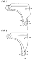
- Fig. 7 is a view showing an example of a die-molding portion of the weather strip of the present invention.
- Fig. 8 is a view showing another example of a die-molding portion of the weather strip of the present invention.
- These die-molding portions of the weather strip are to be counterposed to the flat portion 24 plotted by a large number of dots on Fig. 5.
- Reference numeral 80 is a die-molding weather strip
- reference numeral 81 is a base portion
- reference numeral 82 is a hollow seal portion
- reference numeral 83 is a seal lip portion
- reference numeral 84 is a small lip
- reference numeral 85 is a clip member.
- this retainerless weather strip 10 Since this weather strip 10 is attached to the door panel 20 with the clip 16 that is an attaching means except for a retainer, there is provided no rust prevention sealant, which is conventionally coated in the connecting portion between the retainer and the inner panel 21, in the flat portion 24 on the door panel 20. Accordingly, there is no possibility that the weather strip 10 interferes with the rust prevention sealant and that the sealability is deteriorated in the portion. As a result, the sealability between the weather strip 10 and the door panel 20 can be stabilized over the entirety thereof.
- the small lip 14 is provided, which obliquely and upwardly comes into elastic contact, from a lower end portion of the base portion on the automobile exterior side 60, with the flat portion 24 of the door panel 20. Accordingly, an elastically contacting force of this small lip 14 with the door panel 20 is stronger than that generated in a conventional case where the small lip gets on the small arc portion 25 on the door panel. Therefore, the sealability in this portion can be stabilized. Further, since the small lip 14 obliquely comes into elastic contact with the door panel 20, the base portion 11 of the weather strip 10 can be positively prevented from moving upward, and the sealability between the highly expanded sponge member 17, which is attached to a lower face of the base portion 11, and the door panel 20 can be stabilized. Due to the above structure, the sealability between the weather strip 10 and the door panel 20 can be stabilized over the entirety thereof.
- the small lip 14 protrudes from the lower end portion of the base portion 11, it is possible to form a necked portion 15 in the connecting portion 60 of the base portion 11 and the seal lip portion 13.
- the root portion of the small lip becomes narrow and weak. Therefore, it is impossible to ensure a strong elastic force of the small lip, and it is impossible to form a necked portion between the base portion 11 and the seal lip portion.
- the small lip 14 protrudes from a lower end portion of the base portion 11. Accordingly, even when the necked portion 15 is formed in the portion concerned, the size of the root portion is not affected, and the elastic force of the small lip 14 is not affected by forming the necked portion 15.
- this necked portion 15 When the weather strip 10 is subjected to final machining, this necked portion 15 performs a very important role.
- a hole for inserting the clip 16 or a drain hole is formed by machining the base portion 11 of the weather strip 10, or when the clip 16 is inserted into the clip hole, the necked portion 15 performs a role of the support portion for receiving the guide 40 (see figure 6).
- this final machining can be conducted not manually but mechanically. Therefore, productivity can be greatly enhanced.
- the retainerless weather strip 10 of the comparative example is attached to the door panel 20 by an attaching means except for a retainer. Accordingly, there is provided no rust prevention sealant 54 which is conventionally coated in the connecting portion between the retainer and the inner panel 21. Accordingly, there is no possibility that the weather strip 10 interferes with the rust prevention sealant 54 and that the sealability is deteriorated in the portion. As a result, the sealability between the weather strip 10 and the door panel 20 can be stabilized over the entirety thereof.
- the small lip 14 is provided, which obliquely and upwardly comes into elastic contact, from a lower end portion of the base portion 11 on the automobile exterior side 60, with the flat portion 24 of the door panel 20. Accordingly, an elastically contacting force of this small lip 14 with the door panel 20 is strong. Therefore, the sealability in this portion can be stabilized. Further, since the small lip 14 obliquely comes into elastic contact with the door panel 20, the base portion 11 of the weather strip 10 can be positively prevented from moving upward, and the sealability between the lower face of the base portion 11, and the door panel 20 can be stabilized. Due to the above structure, the sealability between the weather strip 10 and the door panel 20 can be stabilized over the entirety thereof.
- the necked portion 15 formed in the connecting portion of the base portion 11 and the seal lip portion 13 on the automobile exterior side 60 performs function as a supporting portion for receiving the guide 40 when the weather strip 10 is finally machined by a processing machine. Therefore, the final machining of the weather strip 10 can be conducted by the machine. As a result, productivity can be greatly enhanced.
- reference numeral 1 is a weather strip according to the first preferred embodiment, which is for use in a roof portion of an automobile shown in Fig. 1. Only an end edge portion 1b, which protrudes to the automobile exterior side, of an attaching base portion la is made of highly expanded sponge material S.
- Reference numeral 2 is an inner panel of the peripheral edge portion of the door. On the inner panel 2, there is provided an engaging recess 2b at a rising portion of the flat attaching face 2a on the automobile exterior side. An upper end of the engaging recess 2b is connected with the folded portion of 3a of the outer panel 3. On a bottom face of the engaging recess 2b, there is provided a small drain groove 2c.
- the thickness of the highly expanded sponge member S of the end edge portion 1b of the attaching base portion 1a is previously formed to be larger than the engaging recess 2b.
- the weather strip 1 is attached on the door in such a manner that the attaching base portion 1a is fixed onto the attaching face 2a via the clip 4, and the end edge portion 1b of the attaching base portion 1a is press-fitted into the engaging recess 2b. That is, the end edge portion 1b is tightly engaged with the engaging recess 2b, and a strong reaction force is generated in the highly expanded sponge member S. By this strong reaction force, even a portion of the attaching base portion 1a distant from the clip 4 can be strongly fixed onto the inner panel 2. Therefore, it can be expected that the end edge portion 1b can be prevented from coming out from the engaging recess 2b in the same manner as the case where a conventional retainer is used.
- the attaching work can be made simple, that is, only when the end edge portion 1b is pushed into the engaging recess 2b, the attaching work can be completed. Further, water that has entered into the weather strip can be effectively discharged through the drain groove 2c. In this connection, when the door is closed, the hollow seal portion 1c comes into elastic contact with the door opening edge 5 of an automobile body.
- Fig. 10 is a view showing the second embodiment.
- An upper half 6a of the end edge portion 1b of the attaching base portion 1a of the weather strip is made of the same synthetic rubber material E as that of the main body of the weather strip, and the lip or the protrusion 7a is provided in the upper portion thereof, and a lower half 8a of the end edge portion 1b is made of the highly expanded sponge material S.
- the end edge portion 1b enhances an engaging force by the action of the lip or the protrusion 7a, and on the lower surface side of the engaging recess 2b, it is possible to expect that the weather strip is prevented from coming out by the action of the highly expanded sponge member S, which is tightly attached to the engaging recess 2b, in the substantially same manner as that of the first preferred embodiment.
- Fig. 11 is a view showing the third embodiment.
- the upper half 6b of the end edge portion 1b of the attaching base portion 1a of the weather strip is made of the highly expanded sponge material S
- the lower half 8b is made of the same material E as that of the main body of the weather strip
- the protrusion 7b is provided so that the weather strip can be easily inserted into the engaging recess 2b.
- the effect of this embodiment is substantially the same as that of the first and second embodiments described above.
- the attaching structure of the door weather strip of the present invention is composed as follows. All or part of the end edge portion of the attaching base portion of the weather strip is made of a highly expanded sponge material, and the engaging recess is formed at the rising portion of the weather strip attaching face of the inner panel on the automobile exterior side, and the end edge portion of the attaching base portion is press-fitted into this engaging recess. Accordingly, the end edge portion of the attaching base portion of the weather strip can be positively prevented from coming off from the engaging recess by the action of a repelling force generated by the end edge portion made of the highly expanded sponge material that has been compressed. Therefore, it is unnecessary to provide a retainer unlike the conventional structure. Accordingly, the manufacturing cost can be reduced. Further, unlike the conventional structure in which an adhesive tape is used, the weather strip of this embodiment can be easily attached on the door without taking time and labor.
Landscapes
- Engineering & Computer Science (AREA)
- Mechanical Engineering (AREA)
- Seal Device For Vehicle (AREA)
Description
- The present invention relates to a weather strip according to the preamble of
claim 1, to be attached to a door panel of an automobile by an attaching means except for a retainer. It relates further to a weather strip assembly comprising such a weather strip, according toclaim 4. - A weather strip of the kind, with corresponding assembly, is known from
GB 2 334 288 A - Referring to Figs. 1 to 3, related arts are explained below. A full door
type door panel 20 of an automobile usually comprising anouter panel 22 andinner panel 21. On theinner panel 21, there is provided aretainer 53 for attaching aweather strip 50 to theinner panel 21. At a connecting portion of both panels, and also at a connecting portion of theinner panel 21 with theretainer 53, asealant 54 is coated for prevention of rust as shown in Fig. 1. - However, according to the above-described technique, the following problems may be encountered. Since the
rust prevention sealant 54 is coated as described above, theweather strip 50 attached to thedoor panel 20 interferes with thisrust prevention sealant 54. Therefore, it is impossible to obtain a stable sealability between theweather strip 50 and thedoor panel 20. - In order to ensure a stable sealability of the entire weather strip, it is necessary to strongly fasten the
weather strip 50 with theretainer 53 so that theweather strip 50 can be fixed. However, since theweather strip 50 is incorporated into the retainer in a state of simple insertion, theweather strip 50 slips when the door is opened and closed, which possibly deteriorates the sealability. Further, at an end portion of theretainer 53, a step portion, the height of which corresponds to the wall thickness of theretainer 53, is created between theretainer 53 and theinner panel 21. Accordingly, the sealability is damaged at this step portion. For the above reasons, when consideration is given to ensuring the sealability between theweather strip 50 and thedoor panel 20, it is preferable not to provide theretainer 53. - As shown in Fig. 3, in the case of a
weather strip 50 having noretainers 53, it is proposed a means for ensuring the sealability of thedoor panel 20 by providing asmall lip 52 which protrudes from an upper end portion of thebase portion 51 and comes into elastic contact with theinner panel 21. However, the thus composedsmall lip 52 gets on asmall arc portion 25 formed on theinner panel 21, so that the stable sealability can not be ensured. The reason why the stable sealability can not be ensured is described as follows. When thesmall lip 52 gets on thesmall arc portion 25, the sealability in this portion is lowered, and further thesmall lip 52 which has gotten on thesmall arc portion 25 does not sufficiently give a elastically contacting force by which a lower face of thebase portion 51 of theweather strip 50 comes into elastic contact with theinner panel 21. For the above reasons, even when a highly expandedsponge member 17 or an adhesive double coated tape is provided on the lower face of thebase portion 51, it is difficult to obtain a stable sealability. In this case, specific gravity of the highly expanded sponge member is usually in a range from 0.1 to 0.3. - Furthermore, when an adhesive tape is used, it needs an additional step of peeling off a mold releasing paper of the adhesive tape, taking undesirable time and a labor.
- Thus, concerning the
weather strip 50 attached to theretainer 53 provided on a conventional full doortype door panel 20 of an automobile (Fig. 2), it is difficult to stably ensure the sealability between the weather strip and thedoor panel 20. Further, since thesmall strip 52 provided at an upper end portion of the base portion 51 (Fig. 3) gets on thesmall arc portion 25 on thedoor panel 20, the sealability between the weather strip and thedoor panel 20 is deteriorated. -
GB 2334288 A - Accordingly, an object of the present invention is to solve the above-described problems and to provide a retainerless weather strip capable of providing stable sealability thorough the entire length thereof.
- Another object of the present invention is to provide an attaching structure of a door weather strip by which the weight and cost of the weather strip can be reduced and further the time and labor to attach the weather strip can be reduced.
- Other objects and effects of the present invention will become apparent from the following description.
- The above-described objects of the present invention have been achieved by providing the following weather strips and weather strip assemblies.
- (1) A retainerless weather strip attachable to a full door type door panel of an automobile by an attaching means except for a retainer, which comprises:
- a base portion to be fixed to an attaching portion of the door panel by at least one of a clip and an adhesive double coated tape;
- a hollow seal portion provided on an automobile interior side of the base portion when mounted, so as to come into elastic contact with an automobile body;
- a seal lip portion provided on an automobile exterior side of the base portion when mounted, the seal lip portion comprising an upper end portion and an intermediate portion, so that, when mounted on the closed door panel, the upper end portion of the seal lip portion comes into elastic contact with the automobile body and that the intermediate portion of the seal lip portion comes into elastic contact with the door panel;
- an end edge portion protruded from a lower end portion of the base portion on the automobile exterior side; and
- a neck portion formed in a connecting portion of the base portion with the seal lip portion on the automobile exterior side,
- (2) The retainerless weather strip according to the above item (1), wherein an upper half of the end edge portion is made of the same material as that of the main body of the weather strip and has a lip or protrusion provided thereon, and a lower half thereof is made of a highly expanded sponge material.
- (3) The retainerless weather strip according to the above item (1), wherein an upper half of the end edge portion is made of a highly expanded sponge material, and a lower half thereof is made of the same material as that of the main body of the weather strip.
- (4) A retainerless weather strip assembly comprising:
- a retainerless weather strip according to any of the above items (1) to (3) ; and
- an inner panel having an engaging recess for holding the end edge portion of the retainerless weather strip,
- (5) The retainerless weather strip assembly according to the above item (4), wherein the inner panel has a small drain groove on a bottom face of the engaging recess.
- Particular exemplary embodiments in accordance with this invention will now be described with reference to the accompanying drawings; in which:-
- Fig. 1 is a side view showing an automobile to which a weather strip is attached.
- Fig. 2 is a cross-sectional view taken on line A - A in Fig. 1 showing the prior art.
- Fig. 3 is a vertically cross-sectional view showing another prior art.
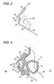
- Fig. 4 is a cross-sectional view taken on line A - A in Fig. 1 showing a comparative example which does not form part of the present invention.
- Fig. 5 is a perspective view showing an outline of a door panel to which a retainerless weather strip of the present invention is attached, wherein Fig. 5 shows a state of the door panel at portion B shown in Fig. 1 when the door panel is viewed from the inside of an automobile.
- Fig. 6 is a vertically cross-sectional view showing a final process of processing a retainerless weather strip of the present invention.
- Fig. 7 is a view showing an embodiment of the present invention, wherein Fig. 7 shows a die-molding portion of the weather strip at portion B shown in Fig. 1.
- Fig. 8 is a view showing another embodiment of the present invention, wherein Fig. 8 shows a die-molding portion of the weather strip at portion B shown in Fig. 1.
- Fig. 9 is a cross-sectional view of an attaching structure of a weather strip of a first embodiment of the present invention taken on line A - A in Fig. 1.
- Fig. 10 is a cross-sectional view of an attaching structure of a weather strip of a second embodiment of the present invention.
- Fig. 11 is a cross-sectional view of an attaching structure of a weather strip of a third embodiment of the present invention.
- The comparative example is shown in Fig. 4. The
retainerless weather strip 10 of this example is attached to a full doortype door panel 20 of an automobile by a means except for a retainer. In thisweather strip 10, there is provided ahollow seal portion 12 on the automobileinterior side 70 of abase portion 11 which is fixed to an attachingportion 23 on adoor panel 20 with aclip 16, and also there is provided aseal lip portion 13 on an automobileexterior side 60. Thehollow seal portion 12 comes into elastic contact with abody 30, and an upper end portion of theseal lip portion 13 comes into elastic contact with thebody 30, and further an intermediate portion of theseal lip portion 13 comes into elastic contact with thedoor panel 20. - In this connection, instead of the
clip 16, an adhesive double coated tape (not shown), or both the adhesive double coated tape and theclip 16 may be provided between thebase portion 11 and theinner panel 21. - Further, also provided is a
small lip 14 which obliquely and upwardly comes into elastic contact, from alower end portion 24 of thebase portion 11 on the automobileexterior side 60, with aflat portion 24 of thedoor panel 20. Furthermore, anecked part 15 is formed on the automobileexterior side 60 in a connecting portion of thebase portion 11 and theseal lip portion 13. Moreover, a highly expandedsponge member 17 can be provided on a lower face of thebase portion 11 on the automobileexterior side 60. Due to the above structure, the sealability between the weather strip and thedoor panel 20 can be stabilized. - Fig. 7 is a view showing an example of a die-molding portion of the weather strip of the present invention. Fig. 8 is a view showing another example of a die-molding portion of the weather strip of the present invention. These die-molding portions of the weather strip are to be counterposed to the
flat portion 24 plotted by a large number of dots on Fig. 5.Reference numeral 80 is a die-molding weather strip,reference numeral 81 is a base portion,reference numeral 82 is a hollow seal portion,reference numeral 83 is a seal lip portion,reference numeral 84 is a small lip, andreference numeral 85 is a clip member. - Next, the action of this
retainerless weather strip 10 is explained below. Since thisweather strip 10 is attached to thedoor panel 20 with theclip 16 that is an attaching means except for a retainer, there is provided no rust prevention sealant, which is conventionally coated in the connecting portion between the retainer and theinner panel 21, in theflat portion 24 on thedoor panel 20. Accordingly, there is no possibility that theweather strip 10 interferes with the rust prevention sealant and that the sealability is deteriorated in the portion. As a result, the sealability between theweather strip 10 and thedoor panel 20 can be stabilized over the entirety thereof. - Since no retainer is required in this comparative example, no material cost, processing cost and attaching work cost for a retainer are required. Therefore, productivity can be greatly enhanced.
- In this
weather strip 10, thesmall lip 14 is provided, which obliquely and upwardly comes into elastic contact, from a lower end portion of the base portion on theautomobile exterior side 60, with theflat portion 24 of thedoor panel 20. Accordingly, an elastically contacting force of thissmall lip 14 with thedoor panel 20 is stronger than that generated in a conventional case where the small lip gets on thesmall arc portion 25 on the door panel. Therefore, the sealability in this portion can be stabilized. Further, since thesmall lip 14 obliquely comes into elastic contact with thedoor panel 20, thebase portion 11 of theweather strip 10 can be positively prevented from moving upward, and the sealability between the highly expandedsponge member 17, which is attached to a lower face of thebase portion 11, and thedoor panel 20 can be stabilized. Due to the above structure, the sealability between theweather strip 10 and thedoor panel 20 can be stabilized over the entirety thereof. - Since the
small lip 14 protrudes from the lower end portion of thebase portion 11, it is possible to form anecked portion 15 in the connectingportion 60 of thebase portion 11 and theseal lip portion 13. When the small lip is protruded from an upper end portion of thebase portion 11 like a conventional technique, the root portion of the small lip becomes narrow and weak. Therefore, it is impossible to ensure a strong elastic force of the small lip, and it is impossible to form a necked portion between thebase portion 11 and the seal lip portion. However, according to theweather strip 10 of the comparative example, thesmall lip 14 protrudes from a lower end portion of thebase portion 11. Accordingly, even when thenecked portion 15 is formed in the portion concerned, the size of the root portion is not affected, and the elastic force of thesmall lip 14 is not affected by forming thenecked portion 15. - When the
weather strip 10 is subjected to final machining, thisnecked portion 15 performs a very important role. When a hole for inserting theclip 16 or a drain hole is formed by machining thebase portion 11 of theweather strip 10, or when theclip 16 is inserted into the clip hole, thenecked portion 15 performs a role of the support portion for receiving the guide 40 (see figure 6). When thisnecked portion 15 is provided, this final machining can be conducted not manually but mechanically. Therefore, productivity can be greatly enhanced. - The
retainerless weather strip 10 of the comparative example is attached to thedoor panel 20 by an attaching means except for a retainer. Accordingly, there is provided norust prevention sealant 54 which is conventionally coated in the connecting portion between the retainer and theinner panel 21. Accordingly, there is no possibility that theweather strip 10 interferes with therust prevention sealant 54 and that the sealability is deteriorated in the portion. As a result, the sealability between theweather strip 10 and thedoor panel 20 can be stabilized over the entirety thereof. - Further, no retainer is required. Accordingly, no material cost, processing cost and attaching work cost are required. Therefore, productivity can be greatly enhanced.
- In this
weather strip 10, thesmall lip 14 is provided, which obliquely and upwardly comes into elastic contact, from a lower end portion of thebase portion 11 on theautomobile exterior side 60, with theflat portion 24 of thedoor panel 20. Accordingly, an elastically contacting force of thissmall lip 14 with thedoor panel 20 is strong. Therefore, the sealability in this portion can be stabilized. Further, since thesmall lip 14 obliquely comes into elastic contact with thedoor panel 20, thebase portion 11 of theweather strip 10 can be positively prevented from moving upward, and the sealability between the lower face of thebase portion 11, and thedoor panel 20 can be stabilized. Due to the above structure, the sealability between theweather strip 10 and thedoor panel 20 can be stabilized over the entirety thereof. - In addition, the
necked portion 15 formed in the connecting portion of thebase portion 11 and theseal lip portion 13 on theautomobile exterior side 60 performs function as a supporting portion for receiving theguide 40 when theweather strip 10 is finally machined by a processing machine. Therefore, the final machining of theweather strip 10 can be conducted by the machine. As a result, productivity can be greatly enhanced. - Referring to Figs. 9 to 11, the first to third preferred embodiments of the present invention are explained in detail below. In Fig. 9,
reference numeral 1 is a weather strip according to the first preferred embodiment, which is for use in a roof portion of an automobile shown in Fig. 1. Only anend edge portion 1b, which protrudes to the automobile exterior side, of an attaching base portion la is made of highly expanded sponge materialS. Reference numeral 2 is an inner panel of the peripheral edge portion of the door. On theinner panel 2, there is provided anengaging recess 2b at a rising portion of the flat attachingface 2a on the automobile exterior side. An upper end of theengaging recess 2b is connected with the folded portion of 3a of theouter panel 3. On a bottom face of theengaging recess 2b, there is provided asmall drain groove 2c. - The thickness of the highly expanded sponge member S of the
end edge portion 1b of the attachingbase portion 1a is previously formed to be larger than theengaging recess 2b. - The
weather strip 1 is attached on the door in such a manner that the attachingbase portion 1a is fixed onto the attachingface 2a via theclip 4, and theend edge portion 1b of the attachingbase portion 1a is press-fitted into the engagingrecess 2b. That is, theend edge portion 1b is tightly engaged with theengaging recess 2b, and a strong reaction force is generated in the highly expanded sponge member S. By this strong reaction force, even a portion of the attachingbase portion 1a distant from theclip 4 can be strongly fixed onto theinner panel 2. Therefore, it can be expected that theend edge portion 1b can be prevented from coming out from the engagingrecess 2b in the same manner as the case where a conventional retainer is used. Accordingly, it is possible to abolish the use of the retainer, and the manufacturing cost can be reduced, and further the attaching work can be made simple, that is, only when theend edge portion 1b is pushed into the engagingrecess 2b, the attaching work can be completed. Further, water that has entered into the weather strip can be effectively discharged through thedrain groove 2c. In this connection, when the door is closed, thehollow seal portion 1c comes into elastic contact with the door opening edge 5 of an automobile body. - Fig. 10 is a view showing the second embodiment. An
upper half 6a of theend edge portion 1b of the attachingbase portion 1a of the weather strip is made of the same synthetic rubber material E as that of the main body of the weather strip, and the lip or theprotrusion 7a is provided in the upper portion thereof, and alower half 8a of theend edge portion 1b is made of the highly expanded sponge material S. Accordingly, on the upper surface side of theengaging recess 2b, theend edge portion 1b enhances an engaging force by the action of the lip or theprotrusion 7a, and on the lower surface side of theengaging recess 2b, it is possible to expect that the weather strip is prevented from coming out by the action of the highly expanded sponge member S, which is tightly attached to theengaging recess 2b, in the substantially same manner as that of the first preferred embodiment. - Fig. 11 is a view showing the third embodiment. In Fig. 11, the
upper half 6b of theend edge portion 1b of the attachingbase portion 1a of the weather strip is made of the highly expanded sponge material S, and thelower half 8b is made of the same material E as that of the main body of the weather strip, and theprotrusion 7b is provided so that the weather strip can be easily inserted into the engagingrecess 2b. The effect of this embodiment is substantially the same as that of the first and second embodiments described above. - As explained above, the attaching structure of the door weather strip of the present invention according to the first to third preferred embodiments is composed as follows. All or part of the end edge portion of the attaching base portion of the weather strip is made of a highly expanded sponge material, and the engaging recess is formed at the rising portion of the weather strip attaching face of the inner panel on the automobile exterior side, and the end edge portion of the attaching base portion is press-fitted into this engaging recess. Accordingly, the end edge portion of the attaching base portion of the weather strip can be positively prevented from coming off from the engaging recess by the action of a repelling force generated by the end edge portion made of the highly expanded sponge material that has been compressed. Therefore, it is unnecessary to provide a retainer unlike the conventional structure. Accordingly, the manufacturing cost can be reduced. Further, unlike the conventional structure in which an adhesive tape is used, the weather strip of this embodiment can be easily attached on the door without taking time and labor.
Claims (5)
- A retainerless weather strip (1) attachable to a full door type door panel (2) of an automobile by an attaching means except for a retainer, which comprises:a base portion (1a) to be fixed to an attaching portion (2a) of the door panel by at least one of a clip (4) and an adhesive double coated tape;a hollow seal portion (1c) provided on an automobile interior side of the base portion when mounted, so as to come into elastic contact with an automobile body (5);a seal lip portion provided on an automobile exterior side of the base portion (1a) when mounted, the seal lip portion comprising an upper end portion and an intermediate portion, so that, when mounted on the closed door panel, the upper end portion of the seal lip portion comes into elastic contact with the automobile body (5) and that the intermediate portion of the seal lip portion comes into elastic contact with the door panel (2); anda neck portion formed in a connecting portion of the base portion with the seal lip portion on the automobile exterior side,characterised in that it further comprises an end edge portion (1b) protruded from a lower end portion of the base portion (1a) on the automobile exterior side, the end edge portion (1b) comprising a portion made of a highly expanded sponge material (S).
- A retainerless weather strip (1) according to claim 1, wherein an upper half (6a) of the end edge portion (1b) is made of the same material (E) as that of the main body of the weather strip and has a lip or protrusion (7a) provided thereon, and a lower half (8a) thereof is made of a highly expanded sponge material (S).
- A retainerless weather strip (1) according to claim 1, wherein an upper half (6b) of the end edge portion (1b) is made of a highly expanded sponge material (S), and a lower half (8b) thereof is made of the same material (E) as that of the main body of the weather strip.
- A retainerless weather strip assembly comprising:a retainerless weather strip (1) according to any one of the preceding claims; andan inner panel (2) having an engaging recess (2b) for holding the end edge portion (1b) of the retainerless weather strip (1),wherein the size of the end edge portion of the retainerless weather strip is larger than that of the engaging recess of the inner panel, and the end edge portion is press-fitted into the engaging recess.
- A retainerless weather strip assembly according to claim 4, wherein the inner panel (2) has a small drain groove (2c) on a bottom face of the engaging recess (2b).
Applications Claiming Priority (4)
| Application Number | Priority Date | Filing Date | Title |
|---|---|---|---|
| JP23712099 | 1999-08-24 | ||
| JP23712099A JP2001063376A (en) | 1999-08-24 | 1999-08-24 | Retainerless weather strip |
| JP31576499A JP2001097044A (en) | 1999-09-29 | 1999-09-29 | Door weatherstrip mounting structure |
| JP31576499 | 1999-09-29 |
Publications (3)
| Publication Number | Publication Date |
|---|---|
| EP1078801A2 EP1078801A2 (en) | 2001-02-28 |
| EP1078801A3 EP1078801A3 (en) | 2001-04-11 |
| EP1078801B1 true EP1078801B1 (en) | 2007-11-07 |
Family
ID=26533057
Family Applications (1)
| Application Number | Title | Priority Date | Filing Date |
|---|---|---|---|
| EP00307262A Expired - Lifetime EP1078801B1 (en) | 1999-08-24 | 2000-08-23 | Retainerless weather strip |
Country Status (4)
| Country | Link |
|---|---|
| US (1) | US6499257B1 (en) |
| EP (1) | EP1078801B1 (en) |
| KR (1) | KR20010030123A (en) |
| DE (1) | DE60036990T2 (en) |
Families Citing this family (21)
| Publication number | Priority date | Publication date | Assignee | Title |
|---|---|---|---|---|
| EP1078801B1 (en) * | 1999-08-24 | 2007-11-07 | Nishikawa Rubber Co., Ltd. | Retainerless weather strip |
| JP3420562B2 (en) * | 2000-09-22 | 2003-06-23 | 東洋ゴム工業株式会社 | Method of manufacturing weatherstrip |
| JP2003002069A (en) * | 2001-04-17 | 2003-01-08 | Kinugawa Rubber Ind Co Ltd | Door weather strip and mounting structure thereof |
| KR100434983B1 (en) * | 2001-08-14 | 2004-06-09 | 현대자동차주식회사 | Structure of parting weather strip |
| JP2004098759A (en) * | 2002-09-05 | 2004-04-02 | Nishikawa Rubber Co Ltd | Weather strip mounting structure |
| DE10304031A1 (en) * | 2003-02-01 | 2004-08-05 | Adam Opel Ag | Sealing system for a closable body opening of a motor vehicle |
| US6814393B2 (en) * | 2003-03-24 | 2004-11-09 | Toyoda Gosei Co., Ltd. | Sealing strip and vehicle panel assembly |
| DE102004004909B4 (en) * | 2004-01-30 | 2006-07-13 | Audi Ag | sealing arrangement |
| JP2007535441A (en) * | 2004-04-30 | 2007-12-06 | 豊田合成株式会社 | Sealing strip and vehicle frame assembly |
| US20060021281A1 (en) * | 2004-08-02 | 2006-02-02 | Toyoda Gosei Co., Ltd | Glass run |
| JP4475529B2 (en) * | 2005-03-31 | 2010-06-09 | 豊田合成株式会社 | Automotive glass run |
| DE102005045298B4 (en) * | 2005-09-22 | 2007-11-22 | Audi Ag | Sealing profile for motor vehicle doors |
| DE102007045659A1 (en) * | 2007-09-25 | 2009-04-02 | Audi Ag | Sealing profile for sealing area between two components of vehicle, particularly area between door pillar and side door of passenger car, has lip protruding from base body |
| CN102416852A (en) * | 2010-09-27 | 2012-04-18 | 鬼怒川橡胶工业株式会社 | Mounting structure of doorframe sealing strip |
| JP5832851B2 (en) * | 2011-10-21 | 2015-12-16 | 西川ゴム工業株式会社 | Door weather strip for automobile |
| GB2504317A (en) * | 2012-07-25 | 2014-01-29 | Gm Global Tech Operations Inc | Fastening clip and gap seal for a vehicle |
| KR101427929B1 (en) * | 2012-12-06 | 2014-08-08 | 현대자동차 주식회사 | Door weather strip for motor vehicle |
| JP5718519B1 (en) * | 2014-11-20 | 2015-05-13 | 西川ゴム工業株式会社 | Door weather strip |
| JP2017171018A (en) * | 2016-03-22 | 2017-09-28 | 西川ゴム工業株式会社 | Door weather strip |
| US10428243B2 (en) * | 2016-12-06 | 2019-10-01 | Ford Motor Company | Method of utilizing thin film pressure sensitive strips to measure pressure applied to a seal |
| US10300777B2 (en) * | 2017-04-11 | 2019-05-28 | Ford Global Technologies, Llc | Truck tailgate system |
Family Cites Families (17)
| Publication number | Priority date | Publication date | Assignee | Title |
|---|---|---|---|---|
| JPS5989220A (en) * | 1982-11-10 | 1984-05-23 | Kinugawa Rubber Ind Co Ltd | Door weather strip for car |
| GB2200390B (en) * | 1987-01-23 | 1991-04-10 | Draftex Ind Ltd | A closure sealing arrangement |
| GB2201711B (en) * | 1987-03-04 | 1990-10-24 | Draftex Ind Ltd | Sealing and trimming strips |
| JPH0618818Y2 (en) * | 1988-05-20 | 1994-05-18 | 豊田合成株式会社 | Car door weather strip |
| JPH07115590B2 (en) * | 1990-11-26 | 1995-12-13 | 豊田合成株式会社 | Automotive door weather strip |
| JP2543917Y2 (en) * | 1991-07-10 | 1997-08-13 | 豊田合成株式会社 | Weather strip |
| JPH0538946A (en) * | 1991-08-07 | 1993-02-19 | Toyo Tire & Rubber Co Ltd | Automotive weatherstrip |
| JP2715761B2 (en) * | 1991-12-05 | 1998-02-18 | 豊田合成株式会社 | Weather strip mounting structure |
| JP3198580B2 (en) * | 1992-01-31 | 2001-08-13 | スズキ株式会社 | Mounting device for weatherstrips for vehicles |
| JPH0612145U (en) * | 1992-07-20 | 1994-02-15 | マツダ株式会社 | Weather strip mounting structure |
| US5590926A (en) * | 1994-02-21 | 1997-01-07 | Toyoda Gosei Co., Ltd. | Structure for attachment of weather strip |
| JPH09123760A (en) * | 1995-11-02 | 1997-05-13 | Toyoda Gosei Co Ltd | Door weather strip attaching structure |
| JPH11227471A (en) * | 1998-02-13 | 1999-08-24 | Toyoda Gosei Co Ltd | Front door weather strip, and manufacture thereof |
| JP3635959B2 (en) * | 1998-12-28 | 2005-04-06 | 豊田合成株式会社 | Door weather strip seal structure |
| EP1078801B1 (en) * | 1999-08-24 | 2007-11-07 | Nishikawa Rubber Co., Ltd. | Retainerless weather strip |
| JP2001097044A (en) * | 1999-09-29 | 2001-04-10 | Nishikawa Rubber Co Ltd | Door weatherstrip mounting structure |
| JP2001063376A (en) * | 1999-08-24 | 2001-03-13 | Nishikawa Rubber Co Ltd | Retainerless weather strip |
-
2000
- 2000-08-23 EP EP00307262A patent/EP1078801B1/en not_active Expired - Lifetime
- 2000-08-23 DE DE60036990T patent/DE60036990T2/en not_active Expired - Lifetime
- 2000-08-24 KR KR1020000049217A patent/KR20010030123A/en not_active Ceased
- 2000-08-24 US US09/644,537 patent/US6499257B1/en not_active Expired - Lifetime
Also Published As
| Publication number | Publication date |
|---|---|
| EP1078801A3 (en) | 2001-04-11 |
| DE60036990T2 (en) | 2008-08-28 |
| US6499257B1 (en) | 2002-12-31 |
| KR20010030123A (en) | 2001-04-16 |
| DE60036990D1 (en) | 2007-12-20 |
| EP1078801A2 (en) | 2001-02-28 |
Similar Documents
| Publication | Publication Date | Title |
|---|---|---|
| US6499257B1 (en) | Retainerless weather strip | |
| KR100290747B1 (en) | Weather Strip | |
| EP1078800B1 (en) | Retainerless weather strip | |
| US6837005B2 (en) | Weatherstrip for automobile | |
| CN102317117A (en) | Trim attachment structure | |
| US5649405A (en) | Weather strip | |
| US20050189782A1 (en) | Mounting structure of automobile door | |
| CA2495365C (en) | Attachment structure for a weather strip | |
| JP3797175B2 (en) | Weather strip mounting structure | |
| JP3879420B2 (en) | Weather strip and its mounting structure | |
| WO2005009767A2 (en) | Sealing, trimming or finishing strips | |
| JP2001063376A (en) | Retainerless weather strip | |
| JP2006193094A (en) | Weather strip | |
| KR100203416B1 (en) | Door weatherstrip | |
| KR0173665B1 (en) | Mounting structure of door frame and weather strip | |
| JP3133843B2 (en) | Automotive door seal structure | |
| JPH0647020U (en) | Automotive weather strip | |
| KR100535621B1 (en) | Door frame structure of automobile | |
| JPH0222349Y2 (en) | ||
| JPH0523380Y2 (en) | ||
| KR0121670Y1 (en) | Weather strip mounting structure for a vehicle door | |
| JPH0617608Y2 (en) | Door outer weather strip | |
| JPH0525295Y2 (en) | ||
| JP2002178748A (en) | Door glass seal structure | |
| JPH07277096A (en) | Drip weather strip |
Legal Events
| Date | Code | Title | Description |
|---|---|---|---|
| PUAI | Public reference made under article 153(3) epc to a published international application that has entered the european phase |
Free format text: ORIGINAL CODE: 0009012 |
|
| PUAL | Search report despatched |
Free format text: ORIGINAL CODE: 0009013 |
|
| AK | Designated contracting states |
Kind code of ref document: A2 Designated state(s): DE FR GB |
|
| AX | Request for extension of the european patent |
Free format text: AL;LT;LV;MK;RO;SI |
|
| AK | Designated contracting states |
Kind code of ref document: A3 Designated state(s): AT BE CH CY DE DK ES FI FR GB GR IE IT LI LU MC NL PT SE |
|
| AX | Request for extension of the european patent |
Free format text: AL;LT;LV;MK;RO;SI |
|
| 17P | Request for examination filed |
Effective date: 20010919 |
|
| AKX | Designation fees paid |
Free format text: DE FR GB |
|
| GRAP | Despatch of communication of intention to grant a patent |
Free format text: ORIGINAL CODE: EPIDOSNIGR1 |
|
| GRAS | Grant fee paid |
Free format text: ORIGINAL CODE: EPIDOSNIGR3 |
|
| GRAA | (expected) grant |
Free format text: ORIGINAL CODE: 0009210 |
|
| AK | Designated contracting states |
Kind code of ref document: B1 Designated state(s): DE FR GB |
|
| REG | Reference to a national code |
Ref country code: GB Ref legal event code: FG4D |
|
| REF | Corresponds to: |
Ref document number: 60036990 Country of ref document: DE Date of ref document: 20071220 Kind code of ref document: P |
|
| ET | Fr: translation filed | ||
| PLBE | No opposition filed within time limit |
Free format text: ORIGINAL CODE: 0009261 |
|
| STAA | Information on the status of an ep patent application or granted ep patent |
Free format text: STATUS: NO OPPOSITION FILED WITHIN TIME LIMIT |
|
| 26N | No opposition filed |
Effective date: 20080808 |
|
| REG | Reference to a national code |
Ref country code: FR Ref legal event code: PLFP Year of fee payment: 17 |
|
| PGFP | Annual fee paid to national office [announced via postgrant information from national office to epo] |
Ref country code: GB Payment date: 20160817 Year of fee payment: 17 Ref country code: DE Payment date: 20160816 Year of fee payment: 17 |
|
| PGFP | Annual fee paid to national office [announced via postgrant information from national office to epo] |
Ref country code: FR Payment date: 20160712 Year of fee payment: 17 |
|
| REG | Reference to a national code |
Ref country code: DE Ref legal event code: R119 Ref document number: 60036990 Country of ref document: DE |
|
| GBPC | Gb: european patent ceased through non-payment of renewal fee |
Effective date: 20170823 |
|
| REG | Reference to a national code |
Ref country code: FR Ref legal event code: ST Effective date: 20180430 |
|
| PG25 | Lapsed in a contracting state [announced via postgrant information from national office to epo] |
Ref country code: DE Free format text: LAPSE BECAUSE OF NON-PAYMENT OF DUE FEES Effective date: 20180301 Ref country code: GB Free format text: LAPSE BECAUSE OF NON-PAYMENT OF DUE FEES Effective date: 20170823 |
|
| PG25 | Lapsed in a contracting state [announced via postgrant information from national office to epo] |
Ref country code: FR Free format text: LAPSE BECAUSE OF NON-PAYMENT OF DUE FEES Effective date: 20170831 |