EP1078674A2 - Pressure swing adsorption process and apparatus - Google Patents
Pressure swing adsorption process and apparatus Download PDFInfo
- Publication number
- EP1078674A2 EP1078674A2 EP00110848A EP00110848A EP1078674A2 EP 1078674 A2 EP1078674 A2 EP 1078674A2 EP 00110848 A EP00110848 A EP 00110848A EP 00110848 A EP00110848 A EP 00110848A EP 1078674 A2 EP1078674 A2 EP 1078674A2
- Authority
- EP
- European Patent Office
- Prior art keywords
- adsorber
- gas
- component
- pressure
- inlet
- Prior art date
- Legal status (The legal status is an assumption and is not a legal conclusion. Google has not performed a legal analysis and makes no representation as to the accuracy of the status listed.)
- Withdrawn
Links
Images


Classifications
-
- B—PERFORMING OPERATIONS; TRANSPORTING
- B01—PHYSICAL OR CHEMICAL PROCESSES OR APPARATUS IN GENERAL
- B01D—SEPARATION
- B01D53/00—Separation of gases or vapours; Recovering vapours of volatile solvents from gases; Chemical or biological purification of waste gases, e.g. engine exhaust gases, smoke, fumes, flue gases, aerosols
- B01D53/02—Separation of gases or vapours; Recovering vapours of volatile solvents from gases; Chemical or biological purification of waste gases, e.g. engine exhaust gases, smoke, fumes, flue gases, aerosols by adsorption, e.g. preparative gas chromatography
- B01D53/04—Separation of gases or vapours; Recovering vapours of volatile solvents from gases; Chemical or biological purification of waste gases, e.g. engine exhaust gases, smoke, fumes, flue gases, aerosols by adsorption, e.g. preparative gas chromatography with stationary adsorbents
- B01D53/047—Pressure swing adsorption
- B01D53/0476—Vacuum pressure swing adsorption
-
- B—PERFORMING OPERATIONS; TRANSPORTING
- B01—PHYSICAL OR CHEMICAL PROCESSES OR APPARATUS IN GENERAL
- B01D—SEPARATION
- B01D53/00—Separation of gases or vapours; Recovering vapours of volatile solvents from gases; Chemical or biological purification of waste gases, e.g. engine exhaust gases, smoke, fumes, flue gases, aerosols
- B01D53/02—Separation of gases or vapours; Recovering vapours of volatile solvents from gases; Chemical or biological purification of waste gases, e.g. engine exhaust gases, smoke, fumes, flue gases, aerosols by adsorption, e.g. preparative gas chromatography
- B01D53/04—Separation of gases or vapours; Recovering vapours of volatile solvents from gases; Chemical or biological purification of waste gases, e.g. engine exhaust gases, smoke, fumes, flue gases, aerosols by adsorption, e.g. preparative gas chromatography with stationary adsorbents
- B01D53/047—Pressure swing adsorption
-
- B—PERFORMING OPERATIONS; TRANSPORTING
- B01—PHYSICAL OR CHEMICAL PROCESSES OR APPARATUS IN GENERAL
- B01D—SEPARATION
- B01D53/00—Separation of gases or vapours; Recovering vapours of volatile solvents from gases; Chemical or biological purification of waste gases, e.g. engine exhaust gases, smoke, fumes, flue gases, aerosols
- B01D53/02—Separation of gases or vapours; Recovering vapours of volatile solvents from gases; Chemical or biological purification of waste gases, e.g. engine exhaust gases, smoke, fumes, flue gases, aerosols by adsorption, e.g. preparative gas chromatography
- B01D53/04—Separation of gases or vapours; Recovering vapours of volatile solvents from gases; Chemical or biological purification of waste gases, e.g. engine exhaust gases, smoke, fumes, flue gases, aerosols by adsorption, e.g. preparative gas chromatography with stationary adsorbents
- B01D53/0407—Constructional details of adsorbing systems
- B01D53/0446—Means for feeding or distributing gases
-
- B—PERFORMING OPERATIONS; TRANSPORTING
- B01—PHYSICAL OR CHEMICAL PROCESSES OR APPARATUS IN GENERAL
- B01D—SEPARATION
- B01D53/00—Separation of gases or vapours; Recovering vapours of volatile solvents from gases; Chemical or biological purification of waste gases, e.g. engine exhaust gases, smoke, fumes, flue gases, aerosols
- B01D53/02—Separation of gases or vapours; Recovering vapours of volatile solvents from gases; Chemical or biological purification of waste gases, e.g. engine exhaust gases, smoke, fumes, flue gases, aerosols by adsorption, e.g. preparative gas chromatography
- B01D53/04—Separation of gases or vapours; Recovering vapours of volatile solvents from gases; Chemical or biological purification of waste gases, e.g. engine exhaust gases, smoke, fumes, flue gases, aerosols by adsorption, e.g. preparative gas chromatography with stationary adsorbents
- B01D53/047—Pressure swing adsorption
- B01D53/053—Pressure swing adsorption with storage or buffer vessel
-
- B—PERFORMING OPERATIONS; TRANSPORTING
- B01—PHYSICAL OR CHEMICAL PROCESSES OR APPARATUS IN GENERAL
- B01D—SEPARATION
- B01D2253/00—Adsorbents used in seperation treatment of gases and vapours
- B01D2253/10—Inorganic adsorbents
- B01D2253/106—Silica or silicates
- B01D2253/108—Zeolites
-
- B—PERFORMING OPERATIONS; TRANSPORTING
- B01—PHYSICAL OR CHEMICAL PROCESSES OR APPARATUS IN GENERAL
- B01D—SEPARATION
- B01D2256/00—Main component in the product gas stream after treatment
- B01D2256/22—Carbon dioxide
-
- B—PERFORMING OPERATIONS; TRANSPORTING
- B01—PHYSICAL OR CHEMICAL PROCESSES OR APPARATUS IN GENERAL
- B01D—SEPARATION
- B01D2257/00—Components to be removed
- B01D2257/10—Single element gases other than halogens
- B01D2257/102—Nitrogen
-
- B—PERFORMING OPERATIONS; TRANSPORTING
- B01—PHYSICAL OR CHEMICAL PROCESSES OR APPARATUS IN GENERAL
- B01D—SEPARATION
- B01D2257/00—Components to be removed
- B01D2257/10—Single element gases other than halogens
- B01D2257/104—Oxygen
-
- B—PERFORMING OPERATIONS; TRANSPORTING
- B01—PHYSICAL OR CHEMICAL PROCESSES OR APPARATUS IN GENERAL
- B01D—SEPARATION
- B01D2257/00—Components to be removed
- B01D2257/10—Single element gases other than halogens
- B01D2257/108—Hydrogen
-
- B—PERFORMING OPERATIONS; TRANSPORTING
- B01—PHYSICAL OR CHEMICAL PROCESSES OR APPARATUS IN GENERAL
- B01D—SEPARATION
- B01D2257/00—Components to be removed
- B01D2257/50—Carbon oxides
- B01D2257/504—Carbon dioxide
-
- B—PERFORMING OPERATIONS; TRANSPORTING
- B01—PHYSICAL OR CHEMICAL PROCESSES OR APPARATUS IN GENERAL
- B01D—SEPARATION
- B01D2257/00—Components to be removed
- B01D2257/70—Organic compounds not provided for in groups B01D2257/00 - B01D2257/602
- B01D2257/702—Hydrocarbons
- B01D2257/7022—Aliphatic hydrocarbons
-
- B—PERFORMING OPERATIONS; TRANSPORTING
- B01—PHYSICAL OR CHEMICAL PROCESSES OR APPARATUS IN GENERAL
- B01D—SEPARATION
- B01D2259/00—Type of treatment
- B01D2259/40—Further details for adsorption processes and devices
- B01D2259/40007—Controlling pressure or temperature swing adsorption
-
- B—PERFORMING OPERATIONS; TRANSPORTING
- B01—PHYSICAL OR CHEMICAL PROCESSES OR APPARATUS IN GENERAL
- B01D—SEPARATION
- B01D2259/00—Type of treatment
- B01D2259/40—Further details for adsorption processes and devices
- B01D2259/402—Further details for adsorption processes and devices using two beds
-
- Y—GENERAL TAGGING OF NEW TECHNOLOGICAL DEVELOPMENTS; GENERAL TAGGING OF CROSS-SECTIONAL TECHNOLOGIES SPANNING OVER SEVERAL SECTIONS OF THE IPC; TECHNICAL SUBJECTS COVERED BY FORMER USPC CROSS-REFERENCE ART COLLECTIONS [XRACs] AND DIGESTS
- Y02—TECHNOLOGIES OR APPLICATIONS FOR MITIGATION OR ADAPTATION AGAINST CLIMATE CHANGE
- Y02C—CAPTURE, STORAGE, SEQUESTRATION OR DISPOSAL OF GREENHOUSE GASES [GHG]
- Y02C20/00—Capture or disposal of greenhouse gases
- Y02C20/40—Capture or disposal of greenhouse gases of CO2
Definitions
- This invention relates to an improved pressure swing adsorption process and apparatus for recovery of the more strongly adsorbed gas component in a multi-component gas mixture. More particularly, it relates to such a process and apparatus for the recovery of carbon dioxide from streams containing more weakly adsorbed components such as nitrogen, oxygen, hydrogen, methane, and carbon monoxide.
- High-purity liquid carbon dioxide (99.99+%) is commonly produced by direct liquefaction of gas streams containing in excess of 95% CO 2 .
- These high-concentration sources are available directly as by-product streams from chemical processes such as ammonia synthesis.
- location of carbon dioxide liquefaction plants is traditionally dictated by the location and availability of these sources.
- Membrane separation processes may also be used for CO 2 recovery, but these processes often require high feed pressures to achieve modest permeability for CO 2 . Expensive multi-staged membrane processes are needed for production of high purity CO 2 from low concentration sources such as flue gas.
- PSA Pressure swing adsorption
- PSA does not require a high temperature energy source like steam for regeneration, as do absorption processes. As a result, PSA is an attractive alternative for locations where steam is unavailable or expensive. In general, adsorptive separation is a reliable, flexible and potentially lower cost method for recovery of CO 2 , particularly when gas-phase purity in excess of 99% is not required.
- the function of the primary adsorbent(s) is to selectively adsorb CO 2 while allowing lighter components to pass through.
- Water, which is typically more strongly adsorbed than CO 2 may be present but can be effectively removed in a pretreatment layer of adsorbent. Therefore, the production of CO 2 using PSA requires processes that are effective for heavy component recovery, that is, for recovery of the more strongly adsorbed component in a multi-component mixture.
- N 2 /O 2 separation utilizing zeolite adsorbents
- CO 2 /N 2 , CO 2 /CH 4 and CO 2 /H 2 separations utilizing zeolites, activated carbons, silica gel or other adsorbents.
- Prior art processes rely on compression of the feed to an elevated adsorption pressure, evacuation to recover heavy component product and rinsing with heavy component.
- Prior art processes typically use multiple beds to insure continuous utilization of equipment, with surge tanks used to dampen fluctuations in product flow and purity.
- Prior art processes for heavy component recovery, or combined light and heavy component recovery can be divided into three general classes: conventional cycles, inverted cycles and reflux cycles.
- adsorption occurs at higher pressure, with purging and recovery of heavy component product taking place at lower pressure.
- an inverted cycle adsorption occurs at lower pressure, with purging at a higher pressure.
- Each adsorbent bed in a reflux cycle contains a conventional bed portion and an inverted bed portion, with reflux of light and heavy component between beds.
- the advantage of the reflux cycle is that both light and heavy component products can be recovered at high purity and high recovery. However, this process is energy intensive and unattractive if recovery of the light component is not desired.
- the inverted cycle can be used to recover heavy component product at high purity, but requires significant power consumption.
- a conventional cycle may consume less power, but heavy component product purity varies throughout the cycle.
- the inverted cycle requires removal of water or other heavy components in a separate vessel before the feed enters the main adsorbent vessels.
- the individual steps in conventional PSA cycles are well known in the prior art.
- the first step in the basic cycle is adsorption, in which a multi-component feed gas is passed to the adsorbent bed at an elevated adsorption pressure. During this step the more selectively adsorbed component is retained by the adsorbent while the gas phase is enriched in less selectively adsorbed components.
- the adsorption step is terminated before the mass transfer front reaches the outlet of the adsorbent bed.
- the adsorber vessel is depressurized via countercurrent blowdown and/or evacuation.
- the gas phase becomes enriched in heavy component. At least a portion of the gas evolved during the depressurization stages is taken as heavy component product.
- the adsorber vessel is repressurized to the adsorption pressure and the cycle is repeated.
- the basic cycle may be modified to include rinsing of the bed with heavy component product between adsorption and depressurization stages. This displaces a portion of the non-adsorbed gas from the bed and provides increased recovery of the heavy component product.
- the cycle may also include purging at intermediate or low pressures to further regenerate the adsorbent before the cycle is repeated.
- Adsorption at elevated pressure requires the compression of large amounts of the light (waste) components; this adds particular energy expense in recovering CO 2 from dilute gas mixtures such as combustion flue gas which may contain as little as 6 to 10% CO 2 , i.e. energy is consumed in compressing 90% or more of the feed gas that is eventually discarded as waste.
- adsorbents such as zeolite 13X or BPL activated carbon.
- zeolite 13X adsorbents
- BPL activated carbon is a much weaker adsorbent for CO 2 , and consequently, does not require such demanding desorption conditions.
- the utility of this adsorbent is diminished for low concentration sources like flue gas because of the weak and nonspecific interaction with CO 2 .
- the equilibrium loadings of N 2 and CO 2 on BPL carbon are nearly identical, resulting in low adsorption selectivity. This low efficiency of separation severely limits the purity and recovery that can be achieved in the process.
- a further object of the invention is to provide such processes and apparatus, requiring lower capital and operating costs than for prior art techniques, particularly for small scale applications.
- Yet an additional object of the invention is to provide improved PSA processes for the recovery of CO 2 from multi-component gas mixtures, by utilizing as adsorbents therein zeolites having particular adiabatic separation factor and dynamic CO 2 loading characteristics.
- a pressure swing adsorption (PSA) process for the recovery of a heavy gas component, e.g., CO 2 , from a multi-component gas mixture comprises:
- the PSA process and apparatus of this invention provide an economical system for heavy component recovery such as CO 2 recovery from gas streams containing up to about 60% CO 2 , e.g., combustion flue gas, lime kiln off-gas or hydrogen plant tail-gas, incorporating more weakly adsorbed, light components such as nitrogen, oxygen, hydrogen, methane and/or carbon monoxide.
- the process is desirably carried out at about atmospheric pressure, i.e., at less than 2 and, preferably at about 1-1.5 atmospheres.
- Other applications include nitrogen recovery from air, heavy hydrocarbon recovery from natural gas, and oxygen recovery from air.
- potential feed sources such as flue gas may contain as little as 6 to 10% CO 2 . Consequently, adsorption at elevated pressure requires the compression of large amounts of light component. If the light component in the feed stream is not a valuable product, compression should be minimized to conserve energy.
- the process of this invention requires only minimal feed compression to overcome pressure drop in the apparatus.
- the adsorbent utilized is chosen to maximize dynamic capacity and selectivity for the heavy component at the feed concentration and at near-ambient adsorption pressures.
- the quantity of displacement gas is minimized, thus further reducing power consumption. Reduced power consumption eliminates the need for the equalization techniques employed in a number of prior art systems to recover compression energy.
- the further use of simultaneous cocurrent/ countercurrent depressurization of the adsorber by exhausting the light component-enriched effluent as a blowdown gas out of the adsorber and into an external vacuum zone while at the same time removing an evacuation stream from the adsorber inlet rejects void gas from the heavy component product.
- the concentration of heavy component in the void spaces at the inlet end of the bed is identical to the feed concentration.
- the heavy component concentration in the gas phase at the inlet of the bed begins to increase from this initial value.
- the exiting gas is enriched in heavy component but is not of product quality.
- a controlled purge is established in the present invention which not only serves to move the heavy component product toward the adsorber inlet but, moreover, may be utilized to effect controlled reduction in pressure in the adsorber bed during purging to maintain constant purity in the product stream. Fluctuations in heavy component purity that typically occur during depressurization are thereby eliminated, removing the need for a large surge vessel to smooth out such fluctuations.
- At least a portion of the product stream recovered in step (4) above is recycled to the inlet of the adsorber to affect cocurrent displacement of the gas mixture at the inlet and thereby increase the inlet concentration of the heavy component, e.g., CO 2 to the desired purity of the product stream.
- the minimum quantity of displacement gas required is dictated by feed and product purity, this minimum quantity of displacement gas is provided to insure compliance with predetermined product purity requirements and also to minimize the consequent power consumption associated therewith.
- the present invention reduces the number of adsorbers and switching valves required by eliminating bed-to-bed interactions.
- Pressure and vacuum tanks provide repressurization and purge gas, and low pressure adsorption eliminates the necessity for equalization to recover pressure energy.
- the process of the present invention can thus be implemented with a single adsorber or, preferably, with two independently but sequentially operable adsorbers to permit continuous utilization of vacuum equipment.
- a PSA apparatus for recovery of a heavy gas component from a feed gas supply of a multi-component gas mixture which comprises:
- the apparatus of the invention may utilize a single adsorber with pressure and vacuum tanks communicating with the outlet end thereof to facilitate repressurization and purging of the adsorber, and a desorption effluent withdrawal means, e.g. a vacuum pump, communicating with the adsorber inlet for removing the heavy component-enriched evacuation and product streams.
- a desorption effluent withdrawal means e.g. a vacuum pump
- While such apparatus of the invention eliminates the need for plural adsorbers and relatively complex switching means for effecting bed-to-bed interactions therebetween it is preferred, in accordance with the invention, to employ a pair of independently operable adsorbers which are operated in staged sequence to provide a continuous flow of the product stream from the inlet end of the adsorber.
- portions of the feed stream may be simultaneously fed through the adsorbers and they may operate in parallel. In either event, operation with two adsorbers allows more efficient utilization of any rotating equipment (compressor and vacuum pump) and hence, increased capacity and efficiency.
- an improved method for selectively recovering CO 2 from multi-component gas mixtures comprising adsorbing the CO 2 at substantially atmospheric pressure in particular adsorbents. That method comprises adsorbing the gas mixture in an adsorbent at feed conditions of about 250 to 450K, more preferred 300 to 400K, and pressures of about 90 to 200 kPa, depressurizing the adsorbent bed to sub-atmospheric pressure to desorb the CO 2 from the bed, and recovering a CO 2 -containing product stream from the bed at substantially constant purity, wherein the adsorbent has an adiabatic separation factor ⁇ CO 2 / ⁇ N 2 in excess of about 1, preferably above 2, and a dynamic DCO 2 loading of at least 0.1 mol/kg at the process operating conditions.
- Adsorbents that provide high working capacity and selectivity in the preferred low pressure range of operation are critical to reducing the quantity of adsorbent needed for a given production rate.
- Zeolite NaY and zeolite NaX(2.0) are exemplary adsorbents for CO 2 that provide reduced bed size factors for production of CO 2 from combustion flue gas, lime kiln off-gas, hydrogen plant tail gas and other sources containing more weakly adsorbed components such as nitrogen, oxygen, hydrogen, methane, and carbon monoxide. Further reduction in adsorbent inventory is achieved by operating with shallow adsorption beds and short cycle times. This increases productivity of the adsorbent and also works to minimize the size of surge volumes if needed to dampen flow rate variations.
- the present invention is directed to the recovery of the more strongly adsorbed gas component in a multi-component gas mixture, by separating such component from more weakly adsorbed components admixed therewith.
- the more strongly adsorbed gas component is identified herein as the "heavy” component, and the more weakly adsorbed components are described as the "light” components of the gas mixture.
- principal reference is made to the recovery of CO 2 as the heavy component of gas mixtures such as combustion flue gas, lime kiln off-gas and/or hydrogen plant tail-gas, containing nitrogen, oxygen, hydrogen, methane, carbon monoxide and/or other light components therein.
- the invention is primarily directed to the recovery of CO 2 from such multi-component gas mixtures, it is not limited to the recovery of CO 2 or to separations from any particular feed-gas source.
- the processes and apparatus of the invention may be used for any multi-component separation in which the more selectively adsorbed component is a desired product.
- This includes, but is not limited to, nitrogen recovery from air using nitrogen-selective adsorbents, oxygen recovery from air using oxygen-selective adsorbents, carbon monoxide recovery from syngas using CO-selective adsorbents, and oxygen/argon separation using either oxygen-selective or argon-selective adsorbents.
- nitrogen recovery from air using nitrogen-selective adsorbents oxygen recovery from air using oxygen-selective adsorbents
- carbon monoxide recovery from syngas using CO-selective adsorbents and oxygen/argon separation using either oxygen-selective or arg
- a single adsorber 4 is utilized incorporating a bed or beds of an appropriate adsorbent or adsorbents, and having an inlet end 4A and an outlet end 4B.
- the inlet end 4A of the adsorber is connected through a two-way valve 3 to a feed blower 2 for supplying a multi-component gas mixture from a feed line 1 to the adsorber, and through a two-way valve 10 to a vacuum pump 11 for evacuating the adsorber to pressures below ambient and for recovering a product stream through line 12.
- feed blower 2 compresses the feed gas only to such an extent as to overcome pressure drop through the system, thereby providing the gaseous feed at a pressure slightly above ambient, atmospheric pressure.
- the feed blower may be eliminated when the feed gas is supplied at sufficient pressure to overcome system ⁇ P.
- the outlet end 4B of the adsorber is connected through a two-way valve 5 to a pressure tank 6, from which effluent may be removed for recovery as a further product stream, or vented, through line 7, or through a control valve 8 to a vacuum tank 9.
- the pressure tank 6 is used to store gas at ambient pressure or above; the vacuum tank 9 is used to store gas at pressures below ambient.
- the pressure tank is preferably a variable volume vessel operating at approximately ambient pressure.
- feed gas is provided to the inlet end 4A of the adsorber 4
- light component effluent from the outlet end 4B of the adsorber is collected in the pressure tank 6 and subsequently reused as repressurization gas
- cocurrent blowdown gas from the outlet end 4B of the adsorber is collected in the vacuum tank 9 and subsequently reused as purge
- heavy component-enriched product is recovered through line 12 from the discharge side of vacuum pump 11.
- a portion, or all, of the light component effluent is collected in the pressure tank 6.
- Some of the light component may be exhausted as waste through line 7 without being returned to the system.
- Two-way switching valves 3, 10 and 5 allow the adsorber 4 to communicate alternately with the blower 2, vacuum pump 11 and pressure tank 6, respectively.
- a control valve 8 is used to regulate flow between the adsorber and the vacuum tank 9.
- step (1) illustrated in Figure 2 feed gas is passed through line 1 to the inlet side of the feed blower 2.
- the two-way valve 3 is opened to allow flow from the outlet of blower 2 into the inlet end 4A of the adsorber 4.
- Effluent from the outlet end 4B of adsorber 4 passes through two-way valve 5 into pressure tank 6.
- At least a portion of the effluent from the adsorber is stored in pressure tank 6, the fraction of effluent to be removed from the system exiting via line 7.
- the multi-component feed gas is thus fed at the adsorption pressure to the inlet of the adsorber, the heavy component being selectively retained by the adsorbent and the gas phase being enriched in the light component or components; at least a portion of the light component effluent from the outlet end of the adsorber is collected and retained in the pressure tank during this step.
- Step (2) simultaneous cocurrent and countercurrent depressurization, is then carried out by closing valve 3 and valve 5, opening control valve 8 to allow flow into vacuum tank 9, and opening the two-way valve 10 to allow flow to vacuum pump 11.
- discharge from vacuum pump 11 is recovered in line 12 and may initially be rejected as waste or recycled with the feed.
- the adsorber is thus simultaneously depressurized cocurrently from its outlet end, and countercurrently from its inlet end; the bed pressure provides the driving force for cocurrent depressurization to the vacuum tank, and the bed pressure and vacuum pump provide the driving force for countercurrent depressurization.
- the cocurrent depressurization gas is collected in the vacuum tank at below ambient pressure for subsequent use as purge gas; the countercurrent depressurization gas in this step consists primarily of void space gas at feed composition from the adsorber inlet and may initially be rejected or recycled with the feed. Enrichment of the heavy component in the countercurrent depressurization gas is minimized in this step by careful balance of the countercurrent and cocurrent blowdown flows.
- step (3) is affected by closing control valve 8 while keeping valve 10 open.
- the flow is thus terminated from the vacuum tank to the outlet end of the adsorber bed while continuing the countercurrent evacuation with the vacuum pump until the purity of the heavy component product meets minimum product purity requirements and the pressure in the adsorber bed is lower than the pressure in the vacuum tank; this countercurrent evacuation gas is enriched in the heavy component and may be rejected as waste or recycled with the feed.
- step (4) the pressure in adsorber 4 will be lower than in vacuum tank 9.
- Control valve 8 is opened and used to control the purge stream flowing from vacuum tank 9 into adsorber 4.
- Valve 10 remains open to allow product to be recovered through vacuum pump 11 into line 12. The heavy component product is thus removed from the inlet end of the adsorber while low pressure purge gas is passed from the vacuum tank to the outlet end of the adsorber.
- the purge rate is controlled by the control valve so that pressure and product purity remain constant initially. As product purity begins to decrease, the purge rate is decreased as the pressure in the adsorber falls while maintaining constant product purity. Following this constant purity product make-step, the bed is repressurized to the adsorption pressure.
- step (5) If sufficient gas remains in vacuum tank 9, it may be used to partially repressurize the bed in step (5).
- valve 10 is closed and control valve 8 is fully opened to equalize the pressure in vacuum tank 9 and adsorber vessel 4.
- step (5) would thus partially repressurize the adsorber countercurrently from its outlet end, using the remaining cocurrent depressurization gas from the vacuum tank. Note that the end of step 4 and step 5, if required, serve to restore the vacuum tank to the low pressure required in subsequent steps.
- step (6) partial repressurization with light component effluent is accomplished by opening valve 5 while control valve 8 and valve 10 are closed.
- Light component effluent that was stored in pressure tank 6 during step (1) repressurizes adsorber 4. Partial countercurrent repressurization is thus effected at the outlet end 4B of the adsorber with light component from the pressure tank.
- step (7) is repressurization to the adsorption pressure.
- Valve 5 is closed and valve 3 is opened to allow feed gas to enter adsorber 4.
- the adsorber is thus repressurized to the adsorption pressure in the cocurrent direction using feed gas passed to the adsorber inlet 4A.
- the cycle sequence is complete, and a subsequent cycle may then begin with step (1).
- An alternative embodiment of the invention employs cocurrent displacement with heavy component product during a portion of the process cycle. This requires an additional tank for collecting a portion of the heavy component product for subsequent feed to the adsorber.
- the essential elements of the apparatus for cocurrent displacement are illustrated in Figure 3. Elements 21-32 of the VPSA system shown therein correspond to the like elements 1-12 of the embodiment of the invention illustrated in Figure 1.
- a heavy component storage tank 33 is provided which is connected to the discharge side of vacuum pump 31, and is provided with a discharge line 34 and a recycle line 35 connected to the inlet side of blower 22.
- Valve 36 is a two-way valve that is opened during cocurrent displacement to allow displacement gas to be passed to the inlet side of blower 22.
- Valve 37 is a two-way valve used to stop flow of feed gas during the cocurrent displacement step.
- the cocurrent displacement gas may be passed directly to the inlet of adsorber 24 without passing through blower 22 if the discharge pressure of the vacuum pump is high enough to overcome the pressure drop in the system.
- a portion of the heavy component product recovered from the discharge side of the vacuum pump may thus be temporarily stored in the heavy component storage tank, and thereafter fed to the suction side of the feed blower during a later step in the cycle.
- This heavy component storage tank operates at approximately ambient pressure and may be a variable volume vessel. Only a portion of the heavy component product is recycled back to the adsorber; the remaining fraction is removed from the system as product.
- step (1) feed gas 21 is passed through valve 37 to the inlet side of feed blower 22.
- the two-way valve 23 is opened to allow flow from the outlet of blower 22 into the inlet end 24A of adsorber 24.
- Effluent from the outlet end 24B of adsorber 24 passes through two-way valve 25 into pressure tank 26.
- At least a portion of the effluent from the adsorber is stored in pressure tank 26, the fraction of effluent to be removed from the system exiting via line 27.
- the multi-component feed gas is thus passed at the adsorption pressure to the adsorber inlet, during which the heavy component is selectively adsorbed by the adsorbent material and the gas phase is enriched in the lighter component or components; at least a portion of the light component effluent from the outlet end of the adsorber is collected and retained in the pressure tank during this step.
- Partial cocurrent rinsing with heavy component is accomplished by passing product from the heavy component storage tank 33 through line 35 and valve 36 to the inlet side of blower 22. Valves 23 and 25 remain open. Valve 37 is closed. A portion or all of the effluent from adsorber 24 is stored in pressure tank 26, the fraction of effluent to be removed from the system exiting via line 27. The heavy component product is thus passed from the heavy component storage tank to the inlet of the adsorber; this displaces a portion of the nonadsorbed gas containing a large fraction of light component from the inlet end of the adsorber, increasing the gas phase concentration of heavy component at the inlet end, to the minimum desired product purity.
- the amount of displacement gas is chosen so that the concentration of heavy component recovered from the inlet end of the bed during subsequent depressurization does not drop below the minimum product purity requirements.
- a portion or all of the effluent from the outlet end of the adsorber may be stored in the pressure tank during this step.
- step (3) are then conducted by closing valves 23 and 25, while opening control valve 28 to allow flow into vacuum tank 29, and opening two-way valve 30 to allow flow to vacuum pump 31.
- discharge from vacuum pump 31 is passed through line 32 into the heavy component storage tank 33.
- the portion of product not retained for subsequent cocurrent displacement is removed from the system through line 34.
- the adsorber is simultaneously depressurized cocurrently from its outlet end and countercurrently from its inlet end, the bed pressure providing the driving force for cocurrent depressurization to the vacuum tank, and the bed pressure and vacuum pump providing the driving force for countercurrent depressurization.
- the cocurrent depressurization gas is collected in the vacuum tank at sub-ambient pressure for subsequent use as purge gas; the countercurrent depressurization gas is recovered as heavy component product.
- step (4) is accomplished by closing control valve 28 while keeping valve 30 open. Control valve 28 remains closed until the pressure in the adsorber bed reaches a predetermined level that is lower than the pressure in the vacuum tank; this countercurrent evacuation gas is recovered as heavy component product.
- step (5) the pressure in adsorber 24 will be lower than in vacuum tank 29.
- Control valve 28 is opened and used to control flow from vacuum tank 29 into the adsorber.
- Valve 30 remains open to allow product to be recovered through vacuum pump 31 into line 32.
- the purge rate is controlled by the control valve so that both pressure and product purity remain constant initially; as product purity begins to decrease, the purge rate is decreased to allow pressure in the adsorber to fall in order to restore and maintain constant product purity.
- the bed may be partially repressurized in step (6). If all of the cocurrent depressurization gas that was stored in vacuum tank 29 during step (3) is not used as purge gas during step (5), it may be used to partially repressurize the bed in step (6).
- valve 30 is closed and control valve 28 is fully opened to equalize the pressure in vacuum tank 29 and adsorber 24. Ideally, however, the exact quantity of gas stored in step (3) is used as purge in step (5) and the equalization step (6) may be eliminated.
- step (7) partial repressurization with light component effluent is accomplished by opening valve 25 while control valve 28 and valve 30 are closed. Light component effluent that was stored in pressure tank 26 during step (l) repressurizes adsorber 24.
- step (8) is repressurization to the adsorption pressure.
- Valve 25 is closed and valve 23 is opened to allow feed gas to enter the adsorber 24.
- the adsorber is thus repressurized to its operating pressure in a cocurrent direction using feed gas passed from the feed compressor to the adsorber inlet.
- step (l) At the end of repressurization the cycle sequence is complete, and a subsequent cycle may then begin with step (l).
- Preferred embodiments of the PSA systems of the invention utilize two identical, independently operable adsorbers through which the multi-component gas mixture is sequentially fed and in which the adsorption/desorption operations are carried out in staged sequence such that the product streams recovered from the individual adsorbers are combined to provide a continuous flow of the product stream containing the heavy gas component at the desired purity.
- Each adsorber interacts alternately with the pressure tank, vacuum tank, feed compressor and vacuum pump. There are no direct adsorber-to-adsorber interactions during the cycle.
- Elements 41-48 and 50-53 are the elements of a first adsorber train A, corresponding to elements 1-12 of the single-bed apparatus of Figure 1, and elements 54-58 represent a second adsorber train B cycled with adsorber train A (thus elements 54-58 correspond to elements 43-45, 48 and 51, respectively).
- Control valve 49 is incorporated in the system to control blowdown and purge flows between vacuum tank 5O and the respective adsorber trains A and B.
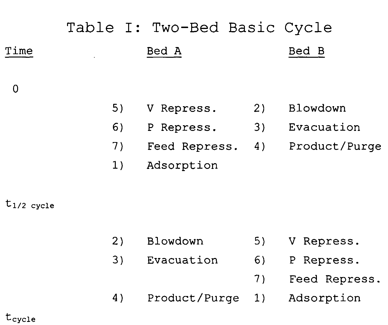
- the cycle steps are balanced such that adsorber train A goes through steps(5), (6), (7) and (1) while adsorber train B is cycled through steps (2), (3) and (4).
- This provides balanced cycle operation which eliminates idle time for the adsorbers, allows more efficient utilization of the rotating equipment, and provides increased capacity. If the optional equalization step (5) is unnecessary the cycle can be balanced so that the vacuum pump is in continuous operation. Otherwise, an idle period equal to the time required for step (5) is necessary to prevent simultaneous interaction between both adsorbers and the vacuum surge tank.
- the most preferred embodiment of the invention employs two adsorbers and cocurrent rinsing with the heavy component product.
- Each adsorber undergoes the same cyclic operation as for the single adsorber in Figures 3 and 4.
- Each adsorber interacts alternately with the pressure tank, vacuum tank, feed compressor and vacuum pump. Again, there are no direct adsorber-to-adsorber interactions during the cycle.
- Two-adsorber operation with cocurrent rinsing allows continuous production of heavy component product, as well as more efficient utilization of the rotating equipment, resulting in the best process efficiency and highest production capacity.
- the essential elements of the cocurrent displacement, two-adsorber bed apparatus are shown in Figure 6.
- the elements 61-78 correspond to elements 41-58 of the two-bed basic apparatus illustrated in Figure 5.
- An additional heavy component storage tank 79 receiving discharge from vacuum pump 72 through line 73 and provided with removal line 80 and recycle line 81 communicating with the inlet side of blower 62 is additionally provided for cocurrent displacement (rinsing).
- Elements 72, 73 and 79-83 correspond, respectively, to elements 31-37 of the single-bed cocurrent displacement apparatus shown in Figure 3, and operate in the same manner as described in connection therewith.
- the cycle steps are balanced so that adsorber train A goes through steps (6), (7) and (8), (1) and (2) while adsorber train B executes steps (3), (4) and (5).
- This provides balanced cycle operation which eliminates idle time for the adsorbers, allows more efficient utilization of the rotating equipment, provides increased capacity, and provides continuous production of heavy component product.
- step (6) is eliminated the cycle can be balanced so that the vacuum pump is in continuous operation. Otherwise, an idle period equal to the time required for step (6) is necessary to prevent simultaneous interaction between both adsorbers and the vacuum surge tank.
- the cocurrent displacement cycle can provide higher throughput and higher purity product --a surprising result since throughput and product purity are usually inversely related.
- Two-adsorber operation is preferred, as it provides continuous utilization of vacuum equipment.
- Two-adsorber operation with partial cocurrent displacement is particularly preferred, as it provides continuous utilization of vacuum equipment and continuous production of heavy component product, in addition to higher throughput.
- Adsorbents useful in the practice of the present invention include the known types of molecular sieve adsorbents, such as those of the zeolite A, X and Y types disclosed, for example, in Milton U.S. Patent Nos. 2,882,243 and 2,882,244.
- the adsorbent(s) utilized are chosen to maximize both the degree of dynamic loading of the heavy component on the adsorbent under the adsorption pressure, temperature and composition, and the degree of separation at the conclusion of the adsorption/desorption cycle between the heavy component to be recovered from the multi-component gas mixture and the lighter component or components thereof.
- the adsorbent may be provided in a single bed, or in multi-layer adsorbent beds such as described in EP-A-0 875 279.
- the most preferred adsorber configuration comprises a pretreatment layer plus a main adsorbent layer in the adsorber or adsorbers utilized.
- One or more adsorbents may be contained in each layer.
- the pretreatment layer is located nearest the feed inlet and its purpose is to remove any undesirable contaminants from the feed stream. Typical contaminants include water, SO x , NO x , and other strongly adsorbed species.
- Typical contaminants include water, SO x , NO x , and other strongly adsorbed species.
- zeolites, activated alumina, silica gel as well as other appropriate adsorbents in the pretreatment zone.
- the pretreatment zone may be eliminated if there are no contaminants in the feed stream.
- the most preferred adsorption pressure is near ambient or slightly above to provide reduced power consumption, particularly for low concentrations of the heavy component in the feed.
- the preferred desorption pressure is sub-atmospheric pressure.
- the most preferred desorption pressure is below the partial pressure of heavy component in the feed.
- the duty of the primary adsorbent(s) is to selectively adsorb CO 2 while allowing lighter components to pass through.
- CO 2 adsorbs strongly on most porous adsorbents, particularly in comparison to many other permanent gases, the strength of adsorption is quite variable.
- Figure 7 presents pure component isotherms at approximately 27°C (300°K) for CO 2 adsorption on several adsorbents. These isotherms demonstrate the varying degree of interaction of CO 2 with solid adsorbents, ranging from weak (e.g., on alumina) to very strong (e.g., on zeolite 5A). The strength of adsorption is primarily indicated by the slope of the isotherms at low pressure. For zeolite 5A, the equilibrium loading at 20 kPa is roughly 90 percent of the equilibrium loading at 200 kPa.
- Steep isotherms such as this require very low desorption pressures in order to adequately desorb CO 2 and to achieve good CO 2 working capacity or dynamic loading between the adsorption and desorption steps.
- the minimal change in loading at higher pressures discourages feed compression.
- Isotherms with less significant slopes at lower pressure may make compression more favorable.
- the performance of adsorbents in a cyclic PSA process is strongly related to the ratio of the dynamic loadings of the strongly held and weakly held components.
- This ratio computed as an adiabatic separation factor, is most accurately calculated from process simulation results by integration of the light and heavy component loadings on the adsorbent bed at the end of the adsorption and desorption stages.
- a reasonable equilibrium approximation of this separation factor can be made directly from isotherms. Initially, the temperature of the feed, gas mixture, and the pressure and gas phase compositions at the end of adsorption and the end of desorption are chosen.
- the most preferred adsorption pressures utilized in the practice of this invention for CO 2 recovery from flue gas are near ambient pressure so as to minimize unnecessary compression of waste gas.
- the adsorbers can be economically evacuated as low as 6 kPa with standard vacuum equipment, so that value is chosen as the minimum desorption pressure.
- a feed composition of 12% CO 2 and 88% N 2 is selected as representative of a typical flue gas stream.
- a desired product purity of 80% CO 2 is chosen for this analysis.
- the flue gas may be available at higher temperatures.
- adsorption temperatures increase, the stronger adsorbents for CO 2 are preferred as their isotherms become less steep and more linear.
- the performance for zeolite 13X can exceed that of zeolite NaY.
- zeolite NaX(2.0), or NaX zeolite with a SiO 2 /Al 2 O 3 ratio equal to 2.0 demonstrates substantially improved performance as compared with zeolite 13X or NaX(2.5).
- Adiabatic separation factors characterize the selectivity of the adsorbents and give a relative measure of the recovery and purity that can be achieved with the process cycle conditions.
- the change in CO 2 loading between the adsorption and desorption stages provides a relative measure of the productivity of the adsorbent. In other words, it determines how much adsorbent will be required for a given CO 2 production rate (referred to as bed size factor).
- bed size factor Variations in these dynamic loadings with different adsorbents are presented in Figure 9.
- zeolite NaY has the highest dynamic loading and hence the smallest bed size factor.
- zeolite NaX(2.0) offers the smallest bed size factor. Smaller bed size factors allow the quantity of adsorbent and the adsorber size to be reduced, providing cost reduction in comparison to the prior art.
- zeolite adsorbents having an adiabatic separation factor, ⁇ CO 2 / ⁇ N 2 , in excess of about 2 and a dynamic CO 2 loading in excess of 0.1 mol/kg, at adsorption temperatures of about 300 to 400_K and under adsorption pressures of about 90 to 200 kPa.
- zeolite NaY has the highest separation factor and highest CO 2 working capacity at moderate adsorption temperatures (less than 340°K).
- NaX(2.0) offers higher separation factors while maintaining relatively high CO2 working capacity.
- These adsorbents may be employed as the main adsorbent layer in the PSA process of the present invention or other pressure swing, vacuum swing or vacuum/pressure swing processes for CO 2 recovery from mixtures with a variety of more weakly adsorbed components such as nitrogen, oxygen, hydrogen, methane, or carbon monoxide.
- Simulation and pilot plant experiments have been used to verify performance of the process and adsorbents of this invention for recovery of CO 2 .
- Representative examples involve the use of zeolite NaY to recover approximately 80% CO 2 product from flue gas containing 12% CO 2 and 88% N 2 .
- Simulation results for the two-bed basic cycle and the two-bed cocurrent displacement cycle are presented in Table III below.
- the basic cycle produces 80% product purity at a recovery of 66%. Recovery is defined herein as the fraction of CO 2 in the feed that is recovered as product.
- the bed size factor (BSF) 341 pounds of zeolite NaY per metric ton per day of contained CO 2 product (lb/mtpd) was achieved for this example. Higher recovery and productivity are obtained by utilizing the two-bed cocurrent displacement cycle of the present invention. With cocurrent displacement, product recovery increases to 75 % while the BSF decreases to 319 pounds of zeolite NaY per metric ton per day of product.
- Additional representative examples involve the use of zeolite NaY in a process to recover approximately 92% CO 2 product from a hydrogen plant tail gas stream containing 54% CO 2 , 16% CH 4 and 30% H 2 .
- Simulation results for the two-bed basic cycle and two-bed cocurrent displacement cycle are presented in Table IV.
- the basic cycle produces 92%CO 2 product at a recovery of 87%.
- the bed size factor is 228 lb/mtpd. Higher recovery and slightly higher productivity are obtained by utilizing the two-bed cocurrent displacement cycle. With this cycle, product recovery increases to 92% while the bed size factor is essentially unchanged at 227 lb/mtpd.
- each adsorber may comprise multiple main adsorbent layers, either without any or with one or more pretreatment layers for the adsorption of other components, e.g., water vapor.
- each adsorbent layer may contain a single adsorbent or a mixture of two or more adsorbents.
- the adsorption pressure may be at or above atmospheric pressure.
- the minimum desorption pressure may be above, at or below atmospheric pressure.
- this invention is primarily addressed to CO 2 recovery from multi-component feed streams, the concepts disclosed herein can be applied to many other separations.
- the processes disclosed may be used for other multi-component separations, with any combination of appropriate adsorbents in which the more selectively adsorbed component is a desired product.
- This includes, but is not limited to, nitrogen recovery from air using nitrogen-selective adsorbents, oxygen recovery from air using oxygen-selective adsorbents, carbon monoxide recovery from syngas using CO-selective adsorbents, and oxygen/argon separation using either oxygen-selective or argon-selective adsorbents.
- this invention may be used for co-production of both light and heavy products, for example, the production of enriched N 2 and enriched CO 2 from flue gas, or enriched N 2 and O 2 from air.
Landscapes
- Chemical & Material Sciences (AREA)
- Engineering & Computer Science (AREA)
- Analytical Chemistry (AREA)
- General Chemical & Material Sciences (AREA)
- Oil, Petroleum & Natural Gas (AREA)
- Chemical Kinetics & Catalysis (AREA)
- Separation Of Gases By Adsorption (AREA)
- Carbon And Carbon Compounds (AREA)
Abstract
Description


Claims (10)
- A pressure swing adsorption process for the recovery of at least a heavy gas component from a multi-component gas mixture, which comprises:(l) feeding the multi-component gas mixture into an inlet of and through at least one adsorber, adsorbing the heavy component of the gas mixture on an adsorbent within the adsorber and removing an effluent enriched with the light component or components of the mixture from the adsorber through an outlet thereof, at least a portion of the light component-enriched effluent being retained in a pressure zone communicating with the adsorber outlet;(2) blowing down a portion of the light component-enriched effluent cocurrently through the adsorber outlet into a vacuum zone maintained at a pressure less than the adsorption pressure and communicating with the adsorber and, at the same time, removing desorbed gas by countercurrent evacuation from the adsorber through the adsorber inlet, to simultaneously depressurize the adsorber cocurrently from its outlet and countercurrently from its inlet;(3) terminating the flow of the blowdown gas through the adsorber outlet while continuing the countercurrent evacuation of the desorbed gas from the adsorber inlet to further depressurize the adsorber until the pressure in the adsorber is less than that in the vacuum zone;(4) passing the blowdown gas as a purge gas stream from the vacuum zone to the adsorber outlet countercurrently to and through the adsorber to make and recover a product stream enriched in the heavy gas component;(5) terminating the flow of the blowdown gas from the vacuum zone and passing light component-enriched effluent from the pressure zone into the outlet of the adsorber to partially repressurize the adsorber;(6) passing an additional portion of the multi-component feed gas mixture into the inlet of the adsorber to complete repressurization of the adsorber; and(7) repeating the foregoing steps to produce the heavy component-containing product stream.
- The pressure swing adsorption process of claim 1, wherein the adsorption in step (1) is carried out at about atmospheric pressure.
- The pressure swing adsorption process of claim 1, wherein CO2 is the heavy gas component recovered, and nitrogen, oxygen, hydrogen, methane, carbon monoxide or other light gases are the light gas component(s) contained in the mixture from which the CO2 is separated.
- The pressure swing adsorption process of claim 3, wherein the adsorbent is zeolite NaY or NaX (2.0).
- The pressure swing adsorption process of claim 1, wherein portions of the multi-component gas mixture are fed in step (1) through two or more independently operable adsorbers, steps (2) -(7) are thereafter separately carried out in the respective adsorbers, and the product streams recovered in step (4) from each adsorber are combined to provide a continuous flow of product enriched in the heavy gas component.
- The pressure swing adsorption process of claim 1, wherein at least a portion of the product stream recovered in step (4) is thereafter recycled to the inlet of the adsorber to effect cocurrent displacement of the gas mixture at the inlet and thereby increase the concentration of the heavy component at the inlet after step (1) of the process.
- The pressure swing adsorption process of claim 1, wherein the flow rate of the purge gas stream in step (4) is controlled during the product make step to provide substantially constant purity of the heavy component-containing product stream.
- The pressure swing adsorption process of claim 1 wherein, after terminating the flow of blowdown gas to make the product stream in step (4), additional blowdown gas from the vacuum zone is passed into the adsorber outlet to augment countercurrent repressurization of the adsorber.
- A process for the recovery of at least CO2 from a multi-component gas mixture containing a less selectively adsorbable component or components selected from nitrogen, oxygen, hydrogen, methane and/or carbon monoxide, wherein the gas mixture is contacted in at least one adsorber containing adsorbent material selective for the adsorption of CO2 by means of cyclic steps comprising:(a) adsorption, during which the gas mixture is passed into the bed in contact with the adsorbent at an adsorption temperature of 300° to 400°K and under an adsorption pressure of 90 to 200 kPa, and the CO2 is selectively adsorbed by the adsorbent;(b) desorption during which the passage of the gas mixture into the bed is discontinued, and the pressure in the bed is reduced from the adsorption pressure to a lower desorption pressure to desorb the CO2 from the bed; and(c) recovering a product stream from the bed containing the CO2 in at least a predetermined, constant purity;
wherein the adsorbent has an adiabatic separation factor ΔCO2/ΔN2 in excess of 2.0 and a dynamic CO2 loading in excess of 0.1 mole/kg at said adsorption temperature and pressure, when the CO2 feed concentration, product concentration and desorption pressure are as set forth in Figure 8. - An apparatus for carrying out a pressure swing adsorption process for the recovery of a heavy gas component in a multi-component gas mixture, which comprises:(1) at least one adsorber having an inlet end and an outlet end and incorporating at least one layer of an adsorbent capable of selectively adsorbing the heavy component of the gas mixture relative to the light component or components thereof;(2) a feed blower communicating with the inlet end of the adsorber for feeding the gas mixture into and through the adsorber;(3) a pressure tank communicating with the outlet end of the adsorber for receiving a light component-enriched effluent from the adsorber and for feeding the light component-enriched effluent into the outlet end of the adsorber;(4) a vacuum tank communicating with the outlet end of the adsorber for receiving a further portion of the light component-enriched effluent from the adsorber and for feeding the light component-enriched effluent as a blowdown gas in the adsorber through its outlet end;(5) outlet valve means for selectively placing the pressure and vacuum tanks in communication with the outlet end of the adsorber for depressurizing and repressurizing the adsorber;(6) a vacuum pump independent of the feed blower and communicating with the inlet end of the adsorber for removing a product stream containing the heavy component of the gas mixture at a predetermined, constant concentration;(7) inlet valve means for selectively placing the feed blower and the vacuum pump in communication with the inlet end of the adsorber to facilitate feed of the gas mixture into and removal of the product stream from the inlet end of the adsorber; and(8) control means for concurrently actuating the outlet valve means and the inlet valve means to facilitate feed of the light component-enriched effluent as a blowdown gas from the vacuum tank into the adsorber and removal of an evacuation stream from the adsorber, to simultaneously depressurize the adsorber cocurrently from its outlet end and countercurrently from its inlet end.
Applications Claiming Priority (2)
| Application Number | Priority Date | Filing Date | Title |
|---|---|---|---|
| US320692 | 1989-03-13 | ||
| US09/320,692 US6245127B1 (en) | 1999-05-27 | 1999-05-27 | Pressure swing adsorption process and apparatus |
Publications (2)
| Publication Number | Publication Date |
|---|---|
| EP1078674A2 true EP1078674A2 (en) | 2001-02-28 |
| EP1078674A3 EP1078674A3 (en) | 2001-11-07 |
Family
ID=23247518
Family Applications (1)
| Application Number | Title | Priority Date | Filing Date |
|---|---|---|---|
| EP00110848A Withdrawn EP1078674A3 (en) | 1999-05-27 | 2000-05-22 | Pressure swing adsorption process and apparatus |
Country Status (9)
| Country | Link |
|---|---|
| US (1) | US6245127B1 (en) |
| EP (1) | EP1078674A3 (en) |
| JP (2) | JP2000354726A (en) |
| KR (1) | KR100524425B1 (en) |
| CN (1) | CN1238090C (en) |
| AR (1) | AR024056A1 (en) |
| BR (1) | BR0002486A (en) |
| CA (1) | CA2308829A1 (en) |
| MX (1) | MXPA00005020A (en) |
Cited By (10)
| Publication number | Priority date | Publication date | Assignee | Title |
|---|---|---|---|---|
| EP1203610A1 (en) * | 2000-11-01 | 2002-05-08 | Air Products And Chemicals, Inc. | Single bed pressure swing adsorption process |
| EP1249264A1 (en) * | 2001-04-11 | 2002-10-16 | Ammonia Casale S.A. | Process for the separation and recovery of carbon dioxide from waste gas or fumes produced by combustible oxidation |
| WO2003020674A1 (en) * | 2001-09-04 | 2003-03-13 | Engelhard Corporation | Co2 rejection from natural gas |
| EP1302233A3 (en) * | 2001-10-12 | 2003-10-01 | Air Products And Chemicals, Inc. | Recovery of nitrogen and light hydrocarbons from polyalkene purge gas |
| FR2889971A1 (en) * | 2005-08-29 | 2007-03-02 | Air Liquide | PRECEDING VALORIZATION OF THE DEPRESSURIZATION GAS OF A VPSA CO2 UNIT |
| EP1867379A3 (en) * | 2006-06-13 | 2008-07-02 | Air Products and Chemicals, Inc. | Pressure swing adsorption process with improved recovery of high-purity product |
| WO2010113118A1 (en) * | 2009-03-31 | 2010-10-07 | L'air Liquide Societe Anonyme Pour L'etude Et L'exploitation Des Procedes Georges Claude | Carbon dioxide recovery from low concentration sources |
| WO2012048814A1 (en) * | 2010-10-16 | 2012-04-19 | Linde Aktiengesellschaft | Method and device for vacuum pressure swing adsorption temporary storage |
| EP2943266A1 (en) * | 2013-01-09 | 2015-11-18 | Invacare Corporation | Product gas concentrator utilizing vacuum swing adsorption and method associated therewith |
| WO2025133702A3 (en) * | 2023-12-22 | 2025-09-18 | Technip Energies France | Pressure swing adsorption with dual-feed, three product streams |
Families Citing this family (95)
| Publication number | Priority date | Publication date | Assignee | Title |
|---|---|---|---|---|
| FR2804729B1 (en) * | 2000-02-07 | 2002-05-10 | Air Liquide | METHOD FOR IMPLEMENTING A FLUID COMPRESSION MACHINE, FLUID TREATMENT PLANT COMPRISING SUCH A MACHINE, AND APPLICATION OF SUCH A PLANT TO THE PRODUCTION OF AN AIR CONSTITUENT |
| KR20030068636A (en) * | 2002-02-15 | 2003-08-25 | 에이엔비 주식회사 | Oxygen Separator |
| US7060382B2 (en) * | 2003-05-15 | 2006-06-13 | Fuelcell Energy, Inc. | Fuel cell system with recycle of anode exhaust gas |
| US7306652B2 (en) * | 2005-03-30 | 2007-12-11 | Parker-Hannifin Corporation | Siloxane removal process |
| CN100355484C (en) * | 2005-11-25 | 2007-12-19 | 刘艳 | Pressure swing absorption decarbonization process and apparatus |
| JP4839114B2 (en) * | 2006-03-27 | 2011-12-21 | 石油コンビナート高度統合運営技術研究組合 | Liquefied carbon dioxide purification equipment |
| US7550030B2 (en) * | 2006-04-03 | 2009-06-23 | Praxair Technology, Inc. | Process and apparatus to recover high purity carbon dioxide |
| US7618478B2 (en) | 2006-04-03 | 2009-11-17 | Praxair Technology, Inc. | Process and apparatus to recover medium purity carbon dioxide |
| FR2906160B1 (en) | 2006-09-25 | 2009-06-05 | Air Liquide | PSA METHOD WITH COMPOSITE ADSORPTION BED FORMED OF ADSORBENT AND AGGLOMERATS OF MCP |
| US7740688B2 (en) * | 2006-09-26 | 2010-06-22 | Praxair Technology, Inc. | Process and apparatus for carbon dioxide recovery |
| WO2009043088A1 (en) * | 2007-10-01 | 2009-04-09 | Dorjoviv Pty Ltd | A method and plant for producing carbonated water |
| CA2702758C (en) * | 2007-11-12 | 2016-08-30 | Exxonmobil Upstream Research Company | Methods of generating and utilizing utility gas |
| DE102008007929A1 (en) * | 2008-02-07 | 2009-08-13 | Linde Aktiengesellschaft | adsorption |
| US20090205493A1 (en) * | 2008-02-20 | 2009-08-20 | Thompson Loren M | Method of removing water from an inlet region of an oxygen generating system |
| US20090205494A1 (en) * | 2008-02-20 | 2009-08-20 | Mcclain Michael S | Single manifold assembly for oxygen-generating systems |
| US20090211443A1 (en) * | 2008-02-21 | 2009-08-27 | Youngblood James H | Self-serviceable filter for an oxygen generating device |
| US7722698B2 (en) * | 2008-02-21 | 2010-05-25 | Delphi Technologies, Inc. | Method of determining the purity of oxygen present in an oxygen-enriched gas produced from an oxygen delivery system |
| US20090214393A1 (en) * | 2008-02-22 | 2009-08-27 | Chekal Michael P | Method of generating an oxygen-enriched gas for a user |
| US8075676B2 (en) | 2008-02-22 | 2011-12-13 | Oxus America, Inc. | Damping apparatus for scroll compressors for oxygen-generating systems |
| US20090229460A1 (en) * | 2008-03-13 | 2009-09-17 | Mcclain Michael S | System for generating an oxygen-enriched gas |
| MY158840A (en) * | 2008-04-30 | 2016-11-15 | Exxonmobil Upstream Res Co | Method and apparatus for removal of oil from utility gas stream |
| US8535417B2 (en) * | 2008-07-29 | 2013-09-17 | Praxair Technology, Inc. | Recovery of carbon dioxide from flue gas |
| US7927573B2 (en) * | 2008-09-26 | 2011-04-19 | Praxair Technology, Inc. | Multi-stage process for purifying carbon dioxide and producing acid |
| FR2937258B1 (en) * | 2008-10-21 | 2011-05-20 | Air Liquide | REPRESSURIZING A VSA PROCESSING A GAS MIXTURE COMPRISING A FUEL |
| CN101954234A (en) * | 2009-07-15 | 2011-01-26 | 中国船舶重工集团公司第七一八研究所 | Carbon dioxide removing machine with double absorbent beds |
| US9067168B2 (en) | 2010-05-28 | 2015-06-30 | Exxonmobil Upstream Research Company | Integrated adsorber head and valve design and swing adsorption methods related thereto |
| US8752390B2 (en) * | 2010-07-13 | 2014-06-17 | Air Products And Chemicals, Inc. | Method and apparatus for producing power and hydrogen |
| CN101898066A (en) * | 2010-07-26 | 2010-12-01 | 成都嘉禾联创科技有限公司 | Method for finely removing carbon dioxide from carbon monoxide |
| TWI495501B (en) | 2010-11-15 | 2015-08-11 | Exxonmobil Upstream Res Co | Kinetic fractionators, and cycling processes for fractionation of gas mixtures |
| US20120148485A1 (en) * | 2010-12-09 | 2012-06-14 | Morrow Jeffrey M | Steam methane reforming process |
| EA201391255A1 (en) | 2011-03-01 | 2014-02-28 | Эксонмобил Апстрим Рисерч Компани | DEVICES AND SYSTEMS HAVING A COMPACT CONFIGURATION OF MULTIPLE LAYERS FOR CYCLIC ADSORPTION AND RELATED METHODS |
| US9352269B2 (en) | 2011-03-01 | 2016-05-31 | Exxonmobil Upstream Research Company | Apparatus and systems having a rotary valve assembly and swing adsorption processes related thereto |
| WO2012118757A1 (en) | 2011-03-01 | 2012-09-07 | Exxonmobil Upstream Research Company | Apparatus and systems having a reciprocating valve head assembly and swing adsorption processes related thereto |
| AU2012223486A1 (en) | 2011-03-01 | 2013-08-15 | Exxonmobil Upstream Research Company | Apparatus and systems having a rotary valve assembly and swing adsorption processes related thereto |
| MY163007A (en) | 2011-03-01 | 2017-07-31 | Exxonmobil Upstream Res Co | Methods of removing contaminants from hydrocarbon stream by swing adsorption and related apparatus and systems |
| US9358493B2 (en) | 2011-03-01 | 2016-06-07 | Exxonmobil Upstream Research Company | Apparatus and systems having an encased adsorbent contactor and swing adsorption processes related thereto |
| AU2012259377B2 (en) | 2011-03-01 | 2016-12-01 | Exxonmobil Upstream Research Company | Methods of removing contaminants from a hydrocarbon stream by swing adsorption and related apparatus and systems |
| US20120279391A1 (en) * | 2011-05-03 | 2012-11-08 | Ravi Kumar | Adsorption process to recover carbon dioxide from flue gas |
| US8709136B2 (en) | 2012-04-03 | 2014-04-29 | Air Products And Chemicals, Inc. | Adsorption process |
| US20130323714A1 (en) * | 2012-06-04 | 2013-12-05 | Alan T. Cheng | System and method for micro-aeration based fermentation |
| CN204891564U (en) * | 2012-07-06 | 2015-12-23 | 道达尔公司 | Apparatus for treating a hydrocarbon feed gas stream containing at least carbon dioxide and hydrogen sulfide to recover a purified CO2 gas stream |
| US9034078B2 (en) | 2012-09-05 | 2015-05-19 | Exxonmobil Upstream Research Company | Apparatus and systems having an adsorbent contactor and swing adsorption processes related thereto |
| KR101917487B1 (en) * | 2014-04-30 | 2018-11-09 | 엑손모빌 케미칼 패턴츠 인코포레이티드 | Method of improving metal-impregnated catalyst performance |
| CA3063636C (en) | 2014-07-25 | 2022-03-01 | Exxonmobil Upstream Research Company | Cyclical swing absorption process and system |
| SG10201912669TA (en) | 2014-11-11 | 2020-02-27 | Exxonmobil Upstream Res Co | High capacity structures and monoliths via paste imprinting |
| US9387430B2 (en) | 2014-11-19 | 2016-07-12 | Apache Corporation | Methods and systems of enhanced carbon dioxide recovery |
| EP3229938A1 (en) | 2014-12-10 | 2017-10-18 | ExxonMobil Research and Engineering Company | Adsorbent-incorporated polymer fibers in packed bed and fabric contactors, and methods and devices using same |
| EP3237091B1 (en) | 2014-12-23 | 2021-08-04 | ExxonMobil Upstream Research Company | Structured adsorbent beds and methods of producing the same |
| US9782715B2 (en) * | 2014-12-30 | 2017-10-10 | Pacific Consolidated Industries, Llc | Load following single bed reversing blower adsorption air separation system |
| CA2979870C (en) | 2015-05-15 | 2019-12-03 | Exxonmobil Upstream Research Company | Apparatus and system for swing adsorption processes related thereto |
| SG11201707069QA (en) | 2015-05-15 | 2017-11-29 | Exxonmobil Upstream Res Co | Apparatus and system for swing adsorption processes related thereto comprising mid-bed purge systems |
| WO2017029142A1 (en) * | 2015-08-19 | 2017-02-23 | Koninklijke Philips N.V. | Oxygen separator with improved efficiency |
| US10124286B2 (en) | 2015-09-02 | 2018-11-13 | Exxonmobil Upstream Research Company | Apparatus and system for swing adsorption processes related thereto |
| CN107847851B (en) | 2015-09-02 | 2021-05-18 | 埃克森美孚上游研究公司 | Swing adsorption method and system using demethanizer overhead stream as sweep gas |
| WO2017048742A1 (en) | 2015-09-16 | 2017-03-23 | Uop Llc | Pressure swing adsorption process and apparatus for purifying a hydrogen-containing gas stream |
| US10322365B2 (en) | 2015-10-27 | 2019-06-18 | Exxonmobil Upstream Reseach Company | Apparatus and system for swing adsorption processes related thereto |
| EA201891029A1 (en) | 2015-10-27 | 2018-10-31 | Эксонмобил Апстрим Рисерч Компани | DEVICE AND SYSTEM FOR PROCESSES OF SHORT-CYCLE ADSORPTION HAVING A VARIETY VARIETY |
| KR102119378B1 (en) | 2015-10-27 | 2020-06-08 | 엑손모빌 업스트림 리서치 캄파니 | Devices and systems for related swing adsorption processes with active controlled feed poppet valves and passively controlled product valves |
| EP3377194A1 (en) | 2015-11-16 | 2018-09-26 | Exxonmobil Upstream Research Company | Adsorbent materials and methods of adsorbing carbon dioxide |
| RU2714063C1 (en) | 2016-03-18 | 2020-02-11 | Эксонмобил Апстрим Рисерч Компани | Apparatus and system for implementing short-cycle adsorption processes |
| AU2017274289B2 (en) | 2016-05-31 | 2020-02-27 | Exxonmobil Upstream Research Company | Apparatus and system for swing adsorption processes |
| WO2017209860A1 (en) | 2016-05-31 | 2017-12-07 | Exxonmobil Upstream Research Company | Apparatus and system for swing adsorption processes |
| US10240486B2 (en) * | 2016-06-27 | 2019-03-26 | Battelle Memorial Institute | Harmonic adsorption recuperative power systems and methods |
| CN107789949B (en) * | 2016-08-30 | 2020-06-16 | 四川天采科技有限责任公司 | Gas separation method by negative pressure swing adsorption |
| US10434458B2 (en) | 2016-08-31 | 2019-10-08 | Exxonmobil Upstream Research Company | Apparatus and system for swing adsorption processes related thereto |
| WO2018044501A1 (en) | 2016-09-01 | 2018-03-08 | Exxonmobil Upstream Research Company | Swing adsorption processes for removing water using 3a zeolite structures |
| US10328382B2 (en) | 2016-09-29 | 2019-06-25 | Exxonmobil Upstream Research Company | Apparatus and system for testing swing adsorption processes |
| AU2017379685B2 (en) | 2016-12-21 | 2020-03-12 | Exxonmobil Upstream Research Company | Self-supporting structures having foam-geometry structure and active materials |
| JP7021227B2 (en) | 2016-12-21 | 2022-02-16 | エクソンモービル アップストリーム リサーチ カンパニー | Self-supporting structure with active material |
| IT201700074132A1 (en) * | 2017-07-03 | 2019-01-03 | Ecospray Tech Srl | SYSTEM AND METHOD OF FILTERING FOR GAS |
| CN107694284A (en) * | 2017-11-09 | 2018-02-16 | 华东理工大学 | A multi-tower replacement vacuum pressure swing adsorption method for concentrating coal bed methane methane |
| KR101987804B1 (en) * | 2017-11-17 | 2019-06-12 | 한국에너지기술연구원 | Pressure swing adsorption method and pressure swing adsorption apparatus |
| WO2019147516A1 (en) | 2018-01-24 | 2019-08-01 | Exxonmobil Upstream Research Company | Apparatus and system for temperature swing adsorption |
| EP3758828A1 (en) | 2018-02-28 | 2021-01-06 | ExxonMobil Upstream Research Company | Apparatus and system for swing adsorption processes |
| FR3078492B1 (en) * | 2018-03-01 | 2022-04-08 | Air Liquide | METHOD FOR ADJUSTING OXYGEN PRODUCTION |
| US11148092B2 (en) | 2018-06-27 | 2021-10-19 | University Of South Carolina | Temperature-vacuum swing adsorption process for capture of CO2 |
| US11007473B2 (en) | 2018-07-09 | 2021-05-18 | University Of South Carolina | Removal of water vapor from streams containing carbon dioxide and/or carbon monoxide |
| CN109613146A (en) * | 2018-12-08 | 2019-04-12 | 苏州贞成分析仪器有限公司 | A kind of adsorption/desorption pipe |
| US11318410B2 (en) | 2018-12-21 | 2022-05-03 | Exxonmobil Upstream Research Company | Flow modulation systems, apparatus, and methods for cyclical swing adsorption |
| WO2020222932A1 (en) | 2019-04-30 | 2020-11-05 | Exxonmobil Upstream Research Company | Rapid cycle adsorbent bed |
| WO2021071755A1 (en) | 2019-10-07 | 2021-04-15 | Exxonmobil Upstream Research Company | Adsorption processes and systems utilizing step lift control of hydraulically actuated poppet valves |
| EP4045173A1 (en) | 2019-10-16 | 2022-08-24 | Exxonmobil Upstream Research Company (EMHC-N1-4A-607) | Dehydration processes utilizing cationic zeolite rho |
| CN112742172B (en) * | 2019-10-31 | 2023-03-24 | 中国石油化工股份有限公司 | Energy gas purification method |
| CN110975606A (en) * | 2019-12-20 | 2020-04-10 | 航电中和山东医疗技术有限公司 | Air purification method and application thereof |
| CN111547690B (en) * | 2020-06-19 | 2024-03-29 | 大连大特气体有限公司 | High-purity electronic grade nitric oxide production device |
| KR20220026347A (en) | 2020-08-25 | 2022-03-04 | 주식회사 클레버 | Vacuum adsorption system for pouch type secondary battery |
| EP4400488A4 (en) * | 2021-09-16 | 2025-01-22 | JFE Steel Corporation | Gas separation method |
| CN116407923B (en) * | 2021-12-31 | 2026-03-10 | 中国石油化工股份有限公司 | Fast cycle pressure swing adsorption process |
| CN115105926B (en) * | 2022-02-17 | 2024-11-19 | 青岛精安医疗科技有限责任公司 | Low-power-consumption oxygen generation system and method |
| CN116812869A (en) * | 2022-03-22 | 2023-09-29 | 国家能源投资集团有限责任公司 | Containing H 2 And CO 2 Method and system for purifying mixed gas and application thereof |
| EP4516380A1 (en) * | 2022-04-28 | 2025-03-05 | Atomis Inc. | Gas recovery device and recovery method |
| KR102795475B1 (en) * | 2023-07-18 | 2025-04-11 | 더 유니버시티 코트 오브 더 유니버시티 오브 에딘버그 | Gas separation methods and systems |
| JP2025126674A (en) * | 2024-02-19 | 2025-08-29 | 日本特殊陶業株式会社 | Recovery system |
| GB2642503A (en) * | 2024-07-11 | 2026-01-14 | Edwards Ltd | Apparatus and method for absorbing a first gas species from a gas mixture |
| JP7841784B1 (en) * | 2025-11-06 | 2026-04-07 | Planet Savers株式会社 | Carbon dioxide adsorbent and its evaluation method |
Family Cites Families (28)
| Publication number | Priority date | Publication date | Assignee | Title |
|---|---|---|---|---|
| US2882244A (en) * | 1953-12-24 | 1959-04-14 | Union Carbide Corp | Molecular sieve adsorbents |
| US2882243A (en) * | 1953-12-24 | 1959-04-14 | Union Carbide Corp | Molecular sieve adsorbents |
| US4599094A (en) | 1985-03-07 | 1986-07-08 | Union Carbide Corporation | Enhanced pressure swing adsorption processing |
| FR2584307B1 (en) | 1985-07-08 | 1989-10-20 | Air Liquide | PROCESS FOR TREATING A GASEOUS MIXTURE BY ADSORPTION |
| JPS6261616A (en) * | 1985-09-11 | 1987-03-18 | Nippon Steel Corp | Method for separating high purity gas from gaseous mixture |
| US4723966A (en) | 1986-12-11 | 1988-02-09 | Union Carbide Corporation | Gas separation by pressure swing adsorption |
| US4810265A (en) | 1987-12-29 | 1989-03-07 | Union Carbide Corporation | Pressure swing adsorption process for gas separation |
| US4892565A (en) | 1987-12-29 | 1990-01-09 | Air Products And Chemicals, Inc. | Adsorptive separation utilizing multiple adsorption beds |
| US4963339A (en) * | 1988-05-04 | 1990-10-16 | The Boc Group, Inc. | Hydrogen and carbon dioxide coproduction |
| US5137549A (en) * | 1988-10-14 | 1992-08-11 | Vbm Corporation | Two stage super-enriched oxygen concentrator |
| CA2016613C (en) * | 1989-05-18 | 1996-03-19 | Ravi Kumar | Adsorptive process for producing two gas streams from a gas mixture |
| US4915711A (en) | 1989-05-18 | 1990-04-10 | Air Products And Chemicals, Inc. | Adsorptive process for producing two gas streams from a gas mixture |
| US5032150A (en) | 1989-11-03 | 1991-07-16 | The Ohio State University | Pressure swing adsorption |
| US5133785A (en) * | 1991-02-26 | 1992-07-28 | Air Products And Chemicals, Inc. | Separation of multicomponent gas mixtures by selective adsorption |
| US5248322A (en) | 1992-10-01 | 1993-09-28 | Air Products And Chemicals, Inc. | Depressurization effluent repressurized adsorption process |
| US5354346A (en) | 1992-10-01 | 1994-10-11 | Air Products And Chemicals, Inc. | Purge effluent repressurized adsorption process |
| US5370728A (en) | 1993-09-07 | 1994-12-06 | Praxair Technology, Inc. | Single bed pressure swing adsorption system and process |
| US5415683A (en) | 1993-11-17 | 1995-05-16 | Praxair Technology, Inc. | Vacuum pressure swing adsorption process |
| US5531808A (en) * | 1994-12-23 | 1996-07-02 | The Boc Group, Inc. | Removal of carbon dioxide from gas streams |
| JP3309197B2 (en) * | 1995-03-02 | 2002-07-29 | 住友精化株式会社 | Recovery method of concentrated oxygen |
| US5565018A (en) * | 1995-07-12 | 1996-10-15 | Praxair Technology, Inc. | Optimal pressure swing adsorption refluxing |
| US5669960A (en) | 1995-11-02 | 1997-09-23 | Praxair Technology, Inc. | Hydrogen generation process |
| US5702504A (en) * | 1996-03-07 | 1997-12-30 | Praxair Technology, Inc. | Vacuum pressure swing adsorption process |
| US5871565A (en) * | 1997-01-15 | 1999-02-16 | Praxair Technology, Inc. | Vacuum/pressure swing adsorption (VPSA) for production of an oxygen enriched gas |
| US5735938A (en) * | 1997-01-15 | 1998-04-07 | Praxair Technology, Inc. | Method for production of nitrogen using oxygen selective adsorbents |
| US6007606A (en) * | 1997-12-09 | 1999-12-28 | Praxair Technology, Inc. | PSA process and system |
| US6048384A (en) * | 1997-12-09 | 2000-04-11 | Smolarek; James | PSA process and system using simultaneous top and bottom evacuation of absorbent bed |
| US6045603A (en) * | 1998-08-21 | 2000-04-04 | The Boc Group, Inc. | Two phase pressure swing adsorption process |
-
1999
- 1999-05-27 US US09/320,692 patent/US6245127B1/en not_active Expired - Lifetime
-
2000
- 2000-05-19 CA CA002308829A patent/CA2308829A1/en not_active Abandoned
- 2000-05-22 AR ARP000102479A patent/AR024056A1/en unknown
- 2000-05-22 EP EP00110848A patent/EP1078674A3/en not_active Withdrawn
- 2000-05-22 JP JP2000149609A patent/JP2000354726A/en active Pending
- 2000-05-22 MX MXPA00005020A patent/MXPA00005020A/en active IP Right Grant
- 2000-05-22 KR KR10-2000-0027416A patent/KR100524425B1/en not_active Expired - Fee Related
- 2000-05-22 CN CNB001089358A patent/CN1238090C/en not_active Expired - Fee Related
- 2000-05-22 BR BR0002486-4A patent/BR0002486A/en not_active IP Right Cessation
-
2006
- 2006-05-02 JP JP2006128060A patent/JP2006239692A/en not_active Abandoned
Cited By (18)
| Publication number | Priority date | Publication date | Assignee | Title |
|---|---|---|---|---|
| EP1203610A1 (en) * | 2000-11-01 | 2002-05-08 | Air Products And Chemicals, Inc. | Single bed pressure swing adsorption process |
| RU2349371C2 (en) * | 2001-04-11 | 2009-03-20 | Аммониа Касале С.А. | Method for separation of waste gas or smoke produced in process of fuel oxidation, and extraction of carbon dioxide from it |
| EP1249264A1 (en) * | 2001-04-11 | 2002-10-16 | Ammonia Casale S.A. | Process for the separation and recovery of carbon dioxide from waste gas or fumes produced by combustible oxidation |
| WO2002083272A1 (en) * | 2001-04-11 | 2002-10-24 | Ammonia Casale S.A. | Process for the preparation and recovery of carbon dioxide from waste gas or fumes produced by combustible oxidation |
| WO2003020674A1 (en) * | 2001-09-04 | 2003-03-13 | Engelhard Corporation | Co2 rejection from natural gas |
| EP1302233A3 (en) * | 2001-10-12 | 2003-10-01 | Air Products And Chemicals, Inc. | Recovery of nitrogen and light hydrocarbons from polyalkene purge gas |
| FR2889971A1 (en) * | 2005-08-29 | 2007-03-02 | Air Liquide | PRECEDING VALORIZATION OF THE DEPRESSURIZATION GAS OF A VPSA CO2 UNIT |
| US7651549B2 (en) | 2006-06-13 | 2010-01-26 | Air Products And Chemicals, Inc. | Pressure swing adsorption process with improved recovery of high-purity product |
| EP1867379A3 (en) * | 2006-06-13 | 2008-07-02 | Air Products and Chemicals, Inc. | Pressure swing adsorption process with improved recovery of high-purity product |
| WO2010113118A1 (en) * | 2009-03-31 | 2010-10-07 | L'air Liquide Societe Anonyme Pour L'etude Et L'exploitation Des Procedes Georges Claude | Carbon dioxide recovery from low concentration sources |
| US8137435B2 (en) | 2009-03-31 | 2012-03-20 | L'air Liquide Societe Anonyme Pour L'etude Et L'exploitation Des Procedes Georges Claude | Carbon dioxide recovery from low concentration sources |
| WO2012048814A1 (en) * | 2010-10-16 | 2012-04-19 | Linde Aktiengesellschaft | Method and device for vacuum pressure swing adsorption temporary storage |
| US8961653B2 (en) | 2010-10-16 | 2015-02-24 | Linde Aktiengesellschaft | Method and device for vacuum pressure swing adsorption with temporary storage |
| AU2011316161B2 (en) * | 2010-10-16 | 2015-03-19 | Linde Aktiengesellschaft | Method and device for vacuum pressure swing adsorption temporary storage |
| RU2579448C2 (en) * | 2010-10-16 | 2016-04-10 | Линде Акциенгезелльшафт | Device and method for adsorption at variable pressure with application of vacuum at intermediate accumulation |
| EP2943266A1 (en) * | 2013-01-09 | 2015-11-18 | Invacare Corporation | Product gas concentrator utilizing vacuum swing adsorption and method associated therewith |
| WO2025133702A3 (en) * | 2023-12-22 | 2025-09-18 | Technip Energies France | Pressure swing adsorption with dual-feed, three product streams |
| EP4585294A3 (en) * | 2023-12-22 | 2025-09-24 | Technip Energies France | Pressure swing adsorption with dual-feed, three product streams |
Also Published As
| Publication number | Publication date |
|---|---|
| KR100524425B1 (en) | 2005-10-28 |
| JP2000354726A (en) | 2000-12-26 |
| AR024056A1 (en) | 2002-09-04 |
| BR0002486A (en) | 2001-01-23 |
| MXPA00005020A (en) | 2002-03-08 |
| CN1238090C (en) | 2006-01-25 |
| CA2308829A1 (en) | 2000-11-27 |
| EP1078674A3 (en) | 2001-11-07 |
| KR20010049382A (en) | 2001-06-15 |
| CN1275422A (en) | 2000-12-06 |
| JP2006239692A (en) | 2006-09-14 |
| US6245127B1 (en) | 2001-06-12 |
Similar Documents
| Publication | Publication Date | Title |
|---|---|---|
| US6245127B1 (en) | Pressure swing adsorption process and apparatus | |
| US5735938A (en) | Method for production of nitrogen using oxygen selective adsorbents | |
| US6660064B2 (en) | Activated carbon as sole absorbent in rapid cycle hydrogen PSA | |
| US5518526A (en) | Pressure swing adsorption process | |
| CA1201662A (en) | Pressure swing absorption system | |
| CN1984705B (en) | Continuous feeding into three-bed pressure swing adsorption system | |
| KR100254295B1 (en) | Pressure swing adsorption process with a single adsorbent bed | |
| CA2199317C (en) | Improved vacuum pressure swing adsorption process | |
| AU2008336265B2 (en) | A plant and process for recovering carbon dioxide | |
| AU646704B2 (en) | Hydrogen and carbon monoxide production by hydrocarbon steam reforming and pressure swing adsorption purification | |
| EP0462778B1 (en) | Pressure swing adsorption method for separating gaseous mixtures | |
| CA2627888C (en) | Pressure swing adsorption process for oxygen production | |
| CN101249370B (en) | Voltage transformation adsorption method for circulation valuable gas | |
| JPH11239711A (en) | PSA method using simultaneous evacuation of top and bottom of adsorbent bed | |
| JPH05228326A (en) | Recovery method of low concentration carbon dioxide | |
| EP0055961B1 (en) | Repressurization process for pressure swing adsorption system | |
| JP2003019415A (en) | Separation method of mixed gas | |
| CA1152902A (en) | Inverted pressure swing adsorption process | |
| MXPA97001724A (en) | Improved procedure of oscillating adsorption devacio-pres |
Legal Events
| Date | Code | Title | Description |
|---|---|---|---|
| PUAI | Public reference made under article 153(3) epc to a published international application that has entered the european phase |
Free format text: ORIGINAL CODE: 0009012 |
|
| AK | Designated contracting states |
Kind code of ref document: A2 Designated state(s): DE ES FR GB IT Kind code of ref document: A2 Designated state(s): AT BE CH CY DE DK ES FI FR GB GR IE IT LI LU MC NL PT SE |
|
| AX | Request for extension of the european patent |
Free format text: AL;LT;LV;MK;RO;SI |
|
| RIN1 | Information on inventor provided before grant (corrected) |
Inventor name: KANE, MICHAEL SCOTT Inventor name: ACKLEY, MARK WILLIAM Inventor name: NOTARO, FRANK Inventor name: LEAVITT, FREDERICK WELLS |
|
| PUAL | Search report despatched |
Free format text: ORIGINAL CODE: 0009013 |
|
| AK | Designated contracting states |
Kind code of ref document: A3 Designated state(s): AT BE CH CY DE DK ES FI FR GB GR IE IT LI LU MC NL PT SE |
|
| AX | Request for extension of the european patent |
Free format text: AL;LT;LV;MK;RO;SI |
|
| 17P | Request for examination filed |
Effective date: 20011120 |
|
| AKX | Designation fees paid |
Free format text: DE ES FR GB IT |
|
| 17Q | First examination report despatched |
Effective date: 20030821 |
|
| GRAP | Despatch of communication of intention to grant a patent |
Free format text: ORIGINAL CODE: EPIDOSNIGR1 |
|
| RTI1 | Title (correction) |
Free format text: PRESSURE SWING ADSORPTION PROCESS |
|
| RTI1 | Title (correction) |
Free format text: PRESSURE SWING ADSORPTION PROCESS |
|
| STAA | Information on the status of an ep patent application or granted ep patent |
Free format text: STATUS: THE APPLICATION IS DEEMED TO BE WITHDRAWN |
|
| 18D | Application deemed to be withdrawn |
Effective date: 20041001 |