EP1078417B1 - Transportschutzvorrichtung - Google Patents
Transportschutzvorrichtung Download PDFInfo
- Publication number
- EP1078417B1 EP1078417B1 EP99921336A EP99921336A EP1078417B1 EP 1078417 B1 EP1078417 B1 EP 1078417B1 EP 99921336 A EP99921336 A EP 99921336A EP 99921336 A EP99921336 A EP 99921336A EP 1078417 B1 EP1078417 B1 EP 1078417B1
- Authority
- EP
- European Patent Office
- Prior art keywords
- support
- main
- portions
- stand
- previous
- Prior art date
- Legal status (The legal status is an assumption and is not a legal conclusion. Google has not performed a legal analysis and makes no representation as to the accuracy of the status listed.)
- Expired - Lifetime
Links
- 238000010276 construction Methods 0.000 claims description 17
- 238000004891 communication Methods 0.000 claims description 11
- 230000001681 protective effect Effects 0.000 claims description 10
- 238000006073 displacement reaction Methods 0.000 claims description 3
- 239000002184 metal Substances 0.000 claims description 3
- 230000003019 stabilising effect Effects 0.000 claims 1
- 239000000463 material Substances 0.000 description 3
- 230000003139 buffering effect Effects 0.000 description 1
- 230000006378 damage Effects 0.000 description 1
- 230000000694 effects Effects 0.000 description 1
- 238000000034 method Methods 0.000 description 1
- 230000000284 resting effect Effects 0.000 description 1
- 239000004753 textile Substances 0.000 description 1
Images




Classifications
-
- H—ELECTRICITY
- H01—ELECTRIC ELEMENTS
- H01Q—ANTENNAS, i.e. RADIO AERIALS
- H01Q1/00—Details of, or arrangements associated with, antennas
- H01Q1/12—Supports; Mounting means
- H01Q1/1235—Collapsible supports; Means for erecting a rigid antenna
Definitions
- This invention concerns a transport protection device according to the preamble of claim 1.
- a satellite communication assembly comprises a box having a base surface which forms the support structure for the active antenna. Means are arranged for providing adjustment of the antenna and the reflector with respect to the body portion. By folding the antenna with the reflector downwards against the body portion, the system may be stored adjacent to the body portion and lids belonging to the box are brought to enclose the system during transport.
- Mobile satellite communication systems should meet demands of being transportable and easily erected. Further they must provide very good direction stability for the antenna lobe in an active position.
- the directional stability demand is nowadays very strict for equipment belonging to the area of the invention, and at present, when effected by wind at a wind force of 15 m/s, the antenna lobe is allowed to deviate maximally 0.4°. This makes it clear that the support needed for a satellite communication system of this kind necessarily has to provide considerable stability.
- the two parts of the support structure in the stand position being fixed along each other or one after the other and, further, a portion of at least the one main portion, and thereby the protective structure itself being outwardly displaceable for forming a support portion, the possibility is ensured to obtain a considerable support surface as well as an easy handled, and easily transportable protective structure.
- the dimensions of the protective structure as such may be minimized in the transport position for obtaining very good transportability, which in practical use is very important in the open field when accessibility to the most varying environments is necessary and wherein vehicle transport can not always be counted upon. Because of the possibility of designing the container slim, such that it is optimized for its containing function in the transport position, its weight may also be held low.
- the feature of claim 2 ensures possibility of fast and convenient transfer to the stand position.
- the feature in claim 3 is preferred, since it brings about symmetrical stable support of the structure at the same time as a preferred double use of the parts included is obtained, which is accentuated through the feature of claim 4, wherein further support action from the free ends of the support portions is made possible with great reliability and in an easy manner.
- the feature of claim 5 ensures possibility of tree-point support, which enhances stability also when erected on an uneven surface.
- the support structure is manufactured as a cage construction and in particularly that the cage construction is comprised of a body of pipes. This accentuates the advantages of low weight and makes it possibility to make a strong structure. Besides, it gives the possibility of achieving simple fixing between the main portions also in case the parts have been subjected to a certain deformation, since with this construction fastenings are easily made on meeting pipe elements. Such a fixation is functioning also if there has been a certain displacement between the pipe elements. Fixing may be made with fastening elements of a per see known kind acting on the pipe elements.
- the cage construction thus gives possibility of stability and rigidity in the transport position as well as in the stand position, but it is not excluded that the structure is built as a panel construction, for example of pressed sheet metal details, for example comprising stiffening ridges in different directions. Also such a construction may be made sufficiently rigid for most applications of the invention.
- the feature of claim 13 result on the one hand in accentuated easily handling of the system, on the other hand of increased stability of the structure in the stand position.
- the feature of claim 14 results in that the structure may be transported as an ordinary hand trolley of a sack trolley type on the two wheels, whereby handles for the operator are arranged at that end of the structure being opposite to the wheels.
- reference 1 concerns a device for transport protection including a cage-shaped pipe construction 2, which comprises a first main portion 3, which is pivotally attached to a second main portion 4 at L.
- the pivot joint L may be arranged differently, but is for example arranged as a piano hinge.
- 5' indicates a first support portion (a second support portion is indicated at 5").
- the support portion 5' is connected to the remaining part of the second main portion 4 over a pivot shaft 6, being arranged at an angle, and is thus outwardly pivotable essentially in the direction of the arrow P 1 .
- a wheel 7 of one pair is shown on the Figure (the other one is covered), with the aid of which the device with its contents may be drawn mainly as a sack trolley, whereby the operator grips the handle portion 9 (see also Fig. 3a).
- a container 10 which in this case is produced from a rigid textile material, and which is arranged to store for transport purposes in a buffering manner i.a. antenna reflector segments.
- the container 10 is constructed as a rigid, relatively form-stable sack, which may be opened with a zipper, when the first main portion 3 has been folded upwards with respect to the second main portion 4.
- a support panel is indicated with 32. 11 indicates storage boxes for various accessories of the communication unit.
- the cage is constructed with a centrally protruding portion 12, which in the stand position, which will be shown in more detail below, will comprise one of three support points for the structure.
- FIG.2 A device according to the invention with the protective structure in the stand position is shown in Fig.2.
- the main portions 3 and 4 are fixed rigidly attached to each other through on the one hand the crossing elongated pivot joint L and on the other hand means at 16 for fixing meetings stays on the respective main portion to each other (will be described below).
- the support portion 5' and 5" are folded outwards over their respective pivot joints 6 and are fixed for obtaining two widely separated support points in the respective lower outer free end of the support portions 5', 5".
- the means for fixing the support portions are also described below.
- the central protruding portion 12 comprises the third support point of the device.
- the main portions are essentially open upwards and in case of the main portion 3 being like a basket, wherein is inserted as ballast a container 14 containing electronic equipment such as antenna power supply.
- This container 14 will thereby comprise very effective ballast with typically a weight of up to 40 kilograms, ensuring stability for the device.
- 17 concerns a support panel included in the second main portion, which panel in the stand position being pivotable at L 2 so that its free end rests against the ground.
- the support panel 17 carries storage boxes 11 for accessories of the satellite communication system, resulting in further ballast.
- 13 indicates a paraboloid, which comprises a reflector for the satellite antenna said paraboloid in a per see known manner being fastened while allowing adjustment along different pivoting shafts over different stays, one of which being shown at 15.
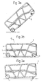
- Fig. 3a shows diagrammatically the position of a device according to the invention when using the wheels (7 in Fig. 1) in order to transport it essentially as a sack trolley.
- the device In Fig. 3b, the device is shown lying on the ground, wherein in this position the main portions 3, 4 are unlocked with respect to each other at 21 so that an upwards pivoting movement of the main portion 3 in the direction of arrow P 2 may be carried out. Thereafter the device is in the position shown in Fig. 3c, whereby the main portions 3 and 4 are locked at 22 for fastening to each other.
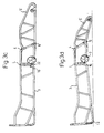
- the device is lifted at the right part, as seen on the Figure, so that the support portions 5', 5" may be pivoted outwardly, in the Figure 3d, 5' in the direction upwardly from the paper, around the pivot shaft 6 and be fixed, whereby a downward displacement is obtained of the free end of the said support portion 5', which ensures safe support abutment of the free end portion of the support portion 5'.
- Three-point support is ensured through the support portions 5', 5" (not shown here) and portion 12. Locking of the support portion in the transport position is ensured with the aid of suitable not shown means. In the position in Fig.
- the wheel 8 is moved downwards, which results in that the device may roll on a relatively even surface on the wheels 7 and 8, where preferably the wheels 8 are swivelling.
- the holder for the wheels 8 is preferably constructed to also lock the support panel 17 in the transport position.
- a device for transport protection having very good transportability at the same time as stability and rigidity is achieved in the transport position, through the great support area with three points, also with possibility of resisting hard winds with minimal effect on the antenna.
- the device may, however, be modified within the scope of the following claims.
- the main portions may also be made as closed panel structures of materials such as pressed metal sheet material.
- further ballast may easily be put in the main portions, which are formed as boxes or baskets, and through the described construction, ground anchors, which are driven into the ground, may easily be connected to the structure in different positions.
- the cage construction is seen clearer since in this case it lacks contents.
- the antenna support is shown at 23.
- the extension is shown of the support panel 17, which also may comprise a sliding surface in case the device is transported drawn as a wide ski over snow covered surfaces.
- the panel is provided with an upward bend, as a ski, in order to enhance movability.
- Fig. 5 shows means for fixing the main portions, in particular the stays S1, S2 (see Fig. 4), which belong to a respective one of the main portions 3 and 4, whereby one means is indicated at position 16 in Fig. 2.
- the fastening elements are arranged such that when they meet, at folding out to the position in Fig. 3c, the screw in the element 25 may be brought to co-operate with the screw hole 27' in the element 26. Tightening is achieved with the aid of the knob 24. In the resting position, the screw is spring biased in the direction to the right in the Figure into protective position inside the element 25. For allowing the screw 27 to easily find the hole 27', it is received with very great play in the hole in the element 25.
- Fig. 6 shows a means for fixing the support portions, wherein the element 25 may be constructed according to the above.
- a fixing plate 29 On the support portion 5', in region of the pivot shaft 6, there is attached a fixing plate 29, which in the transport position is positioned according to the full lines in Fig. 6, and which in the stand position is positioned according to the interrupted lines in Fig. 6. In the latter position, the screw may be drawn into a hole (indicated with 30) in the plate 29.
- a cover 31 is arranged surrounding the movement path of the plate 29.
Landscapes
- Handcart (AREA)
- Support Of Aerials (AREA)
- Radio Relay Systems (AREA)
Claims (15)
- Transportschutzvorrichtung (1) für eine Sattelitenkommunikationseinheit mit einer Schutzstruktur (2), welche in einer Transportstellung zum Aufnehmen der Kommunikationseinheit und in einer Standstellung, einer aktiven Stellung der Kommunikationseinheit, zum Beinhalten eines Sockels hierfür eingerichtet ist, dadurch gekennzeichnet, dass die Schutzstruktur (2) zwei Hauptteile (3, 4) umfasst, von denen jedes eine Innenseite und eine Außenseite aufweist, und welche in der Transportstellung zur Bildung einer im wesentlichen boxförmigen Form mit den Innenseiten zueinander zusammengesetzt sind, und welche in der Standstellung zur Bildung eines vergrößerten Stützbereichs der Länge nach miteinander verbunden sind, und welche in der Standstellung fest aneinander, wobei mindestens ein Teil (5', 5") des mindestens einen Hauptteils (4) seitwärts nach auswärts versetzbar ist, um so ein auf eine Stützfläche einwirkendes stabilisierendes Stützteil zu bilden.
- Vorrichtung nach Anspruch 1, dadurch gekennzeichnet, dass die zwei Hauptteile (3, 4) drehbar zueinander (um L) gelagert sind.
- Vorrichtung nach Anspruch 1 oder 2, dadurch gekennzeichnet, dass eines der Hauptteile (4) zwei nach auswärts drehbar gelagerte Teile (5', 5") umfasst, welche in der Transportstellung zwei gegenüberliegende, im wesentlichen parallele Teile der Stützstruktur bilden.
- Vorrichtung nach Anspruch 1, 2 oder 3, dadurch gekennzeichnet, dass jedes Stützteil (5', 5") mit dem jeweiligen Hauptteil (4) über ein Drehgelenk (6) mit einer bezüglich der Längsrichtung des Hauptteils geneigten Drehwelle verbunden ist, so dass das freie Ende des Stützteils beim auswärts Drehen nach unten versetzt wird.
- Vorrichtung nach Anspruch 3 oder 3 und 4, dadurch gekennzeichnet, dass in der Standstellung die Stützteile (5', 5") sich an einem Ende der Struktur auf der jeweiligen Seite des entsprechenden Hauptteils befinden und dass das andere Hauptteil ein zentral hinausragendes Teil (12) am anderen Ende der Struktur aufweist, so dass eine Dreipunktstütze gegen eine im wesentlichen ebene Oberfläche in der Standstellung erreicht wird.
- Vorrichtung nach einem der vorangegangenen Ansprüche, dadurch gekennzeichnet, dass die Schutzstruktur (2) im wesentlichen aus einer Käfigkonstruktion besteht.
- Vorrichtung nach Anspruch 6, dadurch gekennzeichnet, dass die Käfigkonstruktion aus einem Körper von Rohren besteht.
- Vorrichtung nach einem der Ansprüche 1 bis 5, dadurch gekennzeichnet, dass die Schutzstruktur (2) im wesentlichen eine Plattenkonstruktion ist.
- Vorrichtung nach Anspruch 8, dadurch gekennzeichnet, dass die in der Plattenkonstruktion enthaltenen Platten aus Metallplatten bestehen.
- Vorrichtung nach einem der vorangegangenen Ansprüche, dadurch gekennzeichnet, dass die Hauptteile (3, 4) Teile (16) umfassen, welche senkrecht zu deren Längsrichtung orientiert sind und welche zum Aneinanderbefestigen in der Standstellung eingerichtet sind.
- Vorrichtung nach einem der vorangegangenen Ansprüche, dadurch gekennzeichnet, dass eines der Hauptteile ein Haltemittel (23) enthält, um in der aktiven Stellung der Kommunikationseinheit eine Antenne mit vorzugsweise zusammenlegbarem Reflektor (13) einstellbar zu halten, welche angeordnet ist, um in der Transportstellung von der Struktur (2) umgeben zu sein.
- Vorrichtung nach Anspruch 11, dadurch gekennzeichnet, dass es mindestens ein Befestigungselement für eine Einstellstütze (15) der Antenne mit Reflektor (13) im Abstand von den Haltemitteln (23) gibt.
- Vorrichtung nach einem der vorangegangenen Ansprüche, dadurch gekennzeichnet, dass sie einen für elektronische Ausrüstungen vorgesehenen geschlossenen Behälter (14) umfasst, welcher zur Aufnahme von Ballast zusammen mit seinem Inhalt in der Standstellung vorgesehen ist.
- Vorrichtung nach einem der vorangehenden Ansprüche, dadurch gekennzeichnet, dass die Struktur Räder (7) umfasst, um jene manuell rollen zu können.
- Sattelitenkommunikationsausrüstung, die eine Vorrichtung nach einem der Ansprüche 1 bis 14 enthält.
Priority Applications (1)
| Application Number | Priority Date | Filing Date | Title |
|---|---|---|---|
| DK99921336T DK1078417T3 (da) | 1998-04-06 | 1999-04-06 | Transportbeskyttelsesindretning |
Applications Claiming Priority (3)
| Application Number | Priority Date | Filing Date | Title |
|---|---|---|---|
| SE9801203 | 1998-04-06 | ||
| SE9801203A SE511862C2 (sv) | 1998-04-06 | 1998-04-06 | Anordning för transportskydd av en enhet för satellitkommunikation |
| PCT/SE1999/000562 WO1999052174A1 (en) | 1998-04-06 | 1999-04-06 | Transport protection device |
Publications (2)
| Publication Number | Publication Date |
|---|---|
| EP1078417A1 EP1078417A1 (de) | 2001-02-28 |
| EP1078417B1 true EP1078417B1 (de) | 2005-02-16 |
Family
ID=20410869
Family Applications (1)
| Application Number | Title | Priority Date | Filing Date |
|---|---|---|---|
| EP99921336A Expired - Lifetime EP1078417B1 (de) | 1998-04-06 | 1999-04-06 | Transportschutzvorrichtung |
Country Status (6)
| Country | Link |
|---|---|
| EP (1) | EP1078417B1 (de) |
| AU (1) | AU3857599A (de) |
| DE (1) | DE69923772T2 (de) |
| ES (1) | ES2237101T3 (de) |
| SE (1) | SE511862C2 (de) |
| WO (1) | WO1999052174A1 (de) |
Families Citing this family (2)
| Publication number | Priority date | Publication date | Assignee | Title |
|---|---|---|---|---|
| ITAQ20060010U1 (it) * | 2006-10-30 | 2007-01-29 | Elitalelettronica Italiana S R L | Stazione terrestre satellitare ricetrasmittente, particolarmente idonea per postazioni trasportabili |
| WO2011108015A1 (en) * | 2010-03-04 | 2011-09-09 | Telespazio S.P.A. | Transportable satellite antenna |
Family Cites Families (2)
| Publication number | Priority date | Publication date | Assignee | Title |
|---|---|---|---|---|
| GB2139596B (en) * | 1983-05-13 | 1985-11-20 | Standard Telephones Cables Ltd | Raisable stand |
| US4771293A (en) * | 1984-11-07 | 1988-09-13 | The General Electric Company P.L.C. | Dual reflector folding antenna |
-
1998
- 1998-04-06 SE SE9801203A patent/SE511862C2/sv not_active IP Right Cessation
-
1999
- 1999-04-06 AU AU38575/99A patent/AU3857599A/en not_active Abandoned
- 1999-04-06 ES ES99921336T patent/ES2237101T3/es not_active Expired - Lifetime
- 1999-04-06 EP EP99921336A patent/EP1078417B1/de not_active Expired - Lifetime
- 1999-04-06 DE DE69923772T patent/DE69923772T2/de not_active Expired - Lifetime
- 1999-04-06 WO PCT/SE1999/000562 patent/WO1999052174A1/en not_active Ceased
Also Published As
| Publication number | Publication date |
|---|---|
| SE9801203D0 (sv) | 1998-04-06 |
| WO1999052174A1 (en) | 1999-10-14 |
| SE511862C2 (sv) | 1999-12-06 |
| DE69923772T2 (de) | 2005-11-24 |
| ES2237101T3 (es) | 2005-07-16 |
| SE9801203L (sv) | 1999-10-07 |
| DE69923772D1 (de) | 2005-03-24 |
| AU3857599A (en) | 1999-10-25 |
| EP1078417A1 (de) | 2001-02-28 |
Similar Documents
| Publication | Publication Date | Title |
|---|---|---|
| US8726782B2 (en) | Bullet resistant barrier | |
| US5568848A (en) | Laterally movable suitcase with wheeled, pivotable leg | |
| EP1303436B1 (de) | Plattform mit rädern für eine aufrichtbare schutzhütte | |
| US5197578A (en) | Luggage with four rolling elements | |
| US4852705A (en) | Case with extendable wheels and handle | |
| US20220288475A1 (en) | Equipment for playing basketball | |
| US5553692A (en) | Mobile carrying case | |
| US4244384A (en) | Modular shelter system | |
| KR870000581B1 (ko) | 절첩식 손수레 | |
| US20040216970A1 (en) | Fold-out wheeled support for long, wheeled travel case | |
| US6532991B1 (en) | Air compressor assembly including a handle capable of attaining a plurality of positions | |
| WO1999052174A1 (en) | Transport protection device | |
| GB2171064A (en) | A portable trolley | |
| US7293680B1 (en) | Lifting device | |
| US5902196A (en) | Foldable goal net support | |
| WO1985000398A1 (en) | Portable shelter | |
| US20150320188A1 (en) | Cot and pack-rack | |
| NO347326B1 (en) | Collapsible ballistic protection module | |
| US5463945A (en) | Portable tripod riser | |
| US6413032B1 (en) | Cylinder transporter | |
| US11503887B2 (en) | Mobile carrier canopy assembly | |
| US12588778B2 (en) | Uplifted hands assist device for praying like moses | |
| JP2021129826A (ja) | スーツケース | |
| CA2216412C (en) | Foldable goal net support | |
| GB2339741A (en) | Collapsible wheelbarrow |
Legal Events
| Date | Code | Title | Description |
|---|---|---|---|
| PUAI | Public reference made under article 153(3) epc to a published international application that has entered the european phase |
Free format text: ORIGINAL CODE: 0009012 |
|
| 17P | Request for examination filed |
Effective date: 20000925 |
|
| AK | Designated contracting states |
Kind code of ref document: A1 Designated state(s): DE DK ES FR GB IT |
|
| GRAP | Despatch of communication of intention to grant a patent |
Free format text: ORIGINAL CODE: EPIDOSNIGR1 |
|
| GRAS | Grant fee paid |
Free format text: ORIGINAL CODE: EPIDOSNIGR3 |
|
| GRAA | (expected) grant |
Free format text: ORIGINAL CODE: 0009210 |
|
| AK | Designated contracting states |
Kind code of ref document: B1 Designated state(s): DE DK ES FR GB IT |
|
| REG | Reference to a national code |
Ref country code: GB Ref legal event code: FG4D |
|
| REF | Corresponds to: |
Ref document number: 69923772 Country of ref document: DE Date of ref document: 20050324 Kind code of ref document: P |
|
| RAP2 | Party data changed (patent owner data changed or rights of a patent transferred) |
Owner name: SWE-DISH SATELLITE SYSTEMS AB |
|
| REG | Reference to a national code |
Ref country code: DK Ref legal event code: T3 |
|
| REG | Reference to a national code |
Ref country code: ES Ref legal event code: FG2A Ref document number: 2237101 Country of ref document: ES Kind code of ref document: T3 |
|
| PLBE | No opposition filed within time limit |
Free format text: ORIGINAL CODE: 0009261 |
|
| STAA | Information on the status of an ep patent application or granted ep patent |
Free format text: STATUS: NO OPPOSITION FILED WITHIN TIME LIMIT |
|
| ET | Fr: translation filed | ||
| 26N | No opposition filed |
Effective date: 20051117 |
|
| REG | Reference to a national code |
Ref country code: FR Ref legal event code: CD Ref country code: FR Ref legal event code: CA |
|
| REG | Reference to a national code |
Ref country code: ES Ref legal event code: PC2A |
|
| REG | Reference to a national code |
Ref country code: FR Ref legal event code: PLFP Year of fee payment: 17 |
|
| PGFP | Annual fee paid to national office [announced via postgrant information from national office to epo] |
Ref country code: GB Payment date: 20150424 Year of fee payment: 17 Ref country code: ES Payment date: 20150421 Year of fee payment: 17 Ref country code: DE Payment date: 20150424 Year of fee payment: 17 Ref country code: DK Payment date: 20150422 Year of fee payment: 17 |
|
| PGFP | Annual fee paid to national office [announced via postgrant information from national office to epo] |
Ref country code: IT Payment date: 20150427 Year of fee payment: 17 Ref country code: FR Payment date: 20150430 Year of fee payment: 17 |
|
| REG | Reference to a national code |
Ref country code: DE Ref legal event code: R119 Ref document number: 69923772 Country of ref document: DE |
|
| REG | Reference to a national code |
Ref country code: DK Ref legal event code: EBP Effective date: 20160430 |
|
| GBPC | Gb: european patent ceased through non-payment of renewal fee |
Effective date: 20160406 |
|
| REG | Reference to a national code |
Ref country code: FR Ref legal event code: ST Effective date: 20161230 |
|
| PG25 | Lapsed in a contracting state [announced via postgrant information from national office to epo] |
Ref country code: FR Free format text: LAPSE BECAUSE OF NON-PAYMENT OF DUE FEES Effective date: 20160502 Ref country code: GB Free format text: LAPSE BECAUSE OF NON-PAYMENT OF DUE FEES Effective date: 20160406 Ref country code: DE Free format text: LAPSE BECAUSE OF NON-PAYMENT OF DUE FEES Effective date: 20161101 |
|
| PG25 | Lapsed in a contracting state [announced via postgrant information from national office to epo] |
Ref country code: IT Free format text: LAPSE BECAUSE OF NON-PAYMENT OF DUE FEES Effective date: 20160406 |
|
| PG25 | Lapsed in a contracting state [announced via postgrant information from national office to epo] |
Ref country code: DK Free format text: LAPSE BECAUSE OF NON-PAYMENT OF DUE FEES Effective date: 20160430 |
|
| PG25 | Lapsed in a contracting state [announced via postgrant information from national office to epo] |
Ref country code: ES Free format text: LAPSE BECAUSE OF NON-PAYMENT OF DUE FEES Effective date: 20160407 |
|
| REG | Reference to a national code |
Ref country code: ES Ref legal event code: FD2A Effective date: 20181128 |