EP1077818B1 - Vehicle trailer frame cross member/suspension assembly mount - Google Patents
Vehicle trailer frame cross member/suspension assembly mount Download PDFInfo
- Publication number
- EP1077818B1 EP1077818B1 EP99923053A EP99923053A EP1077818B1 EP 1077818 B1 EP1077818 B1 EP 1077818B1 EP 99923053 A EP99923053 A EP 99923053A EP 99923053 A EP99923053 A EP 99923053A EP 1077818 B1 EP1077818 B1 EP 1077818B1
- Authority
- EP
- European Patent Office
- Prior art keywords
- cross member
- suspension
- members
- trailer frame
- suspension assembly
- Prior art date
- Legal status (The legal status is an assumption and is not a legal conclusion. Google has not performed a legal analysis and makes no representation as to the accuracy of the status listed.)
- Expired - Lifetime
Links
- 239000000725 suspension Substances 0.000 title claims abstract description 133
- 230000000712 assembly Effects 0.000 claims abstract description 13
- 238000000429 assembly Methods 0.000 claims abstract description 13
- 229910000831 Steel Inorganic materials 0.000 claims description 8
- 239000010959 steel Substances 0.000 claims description 8
- 238000000034 method Methods 0.000 claims description 4
- 238000003466 welding Methods 0.000 abstract description 10
- 230000002028 premature Effects 0.000 abstract 1
- 238000004519 manufacturing process Methods 0.000 description 6
- 125000006850 spacer group Chemical group 0.000 description 6
- 239000000463 material Substances 0.000 description 4
- 229910052751 metal Inorganic materials 0.000 description 3
- 239000002184 metal Substances 0.000 description 3
- 239000006096 absorbing agent Substances 0.000 description 2
- 238000010276 construction Methods 0.000 description 2
- 230000035939 shock Effects 0.000 description 2
- 239000003351 stiffener Substances 0.000 description 2
- 229910052782 aluminium Inorganic materials 0.000 description 1
- XAGFODPZIPBFFR-UHFFFAOYSA-N aluminium Chemical compound [Al] XAGFODPZIPBFFR-UHFFFAOYSA-N 0.000 description 1
- 238000005336 cracking Methods 0.000 description 1
- 230000000694 effects Effects 0.000 description 1
- 238000010348 incorporation Methods 0.000 description 1
- 238000009434 installation Methods 0.000 description 1
- 238000003698 laser cutting Methods 0.000 description 1
- 238000005457 optimization Methods 0.000 description 1
- 230000001737 promoting effect Effects 0.000 description 1
- 238000004080 punching Methods 0.000 description 1
- 239000002699 waste material Substances 0.000 description 1
Images









Classifications
-
- B—PERFORMING OPERATIONS; TRANSPORTING
- B62—LAND VEHICLES FOR TRAVELLING OTHERWISE THAN ON RAILS
- B62D—MOTOR VEHICLES; TRAILERS
- B62D21/00—Understructures, i.e. chassis frame on which a vehicle body may be mounted
- B62D21/02—Understructures, i.e. chassis frame on which a vehicle body may be mounted comprising longitudinally or transversely arranged frame members
-
- B—PERFORMING OPERATIONS; TRANSPORTING
- B60—VEHICLES IN GENERAL
- B60G—VEHICLE SUSPENSION ARRANGEMENTS
- B60G7/00—Pivoted suspension arms; Accessories thereof
- B60G7/02—Attaching arms to sprung part of vehicle
-
- B—PERFORMING OPERATIONS; TRANSPORTING
- B60—VEHICLES IN GENERAL
- B60G—VEHICLE SUSPENSION ARRANGEMENTS
- B60G2204/00—Indexing codes related to suspensions per se or to auxiliary parts
- B60G2204/10—Mounting of suspension elements
-
- B—PERFORMING OPERATIONS; TRANSPORTING
- B60—VEHICLES IN GENERAL
- B60G—VEHICLE SUSPENSION ARRANGEMENTS
- B60G2204/00—Indexing codes related to suspensions per se or to auxiliary parts
- B60G2204/10—Mounting of suspension elements
- B60G2204/12—Mounting of springs or dampers
- B60G2204/126—Mounting of pneumatic springs
-
- B—PERFORMING OPERATIONS; TRANSPORTING
- B60—VEHICLES IN GENERAL
- B60G—VEHICLE SUSPENSION ARRANGEMENTS
- B60G2204/00—Indexing codes related to suspensions per se or to auxiliary parts
- B60G2204/10—Mounting of suspension elements
- B60G2204/14—Mounting of suspension arms
- B60G2204/143—Mounting of suspension arms on the vehicle body or chassis
-
- B—PERFORMING OPERATIONS; TRANSPORTING
- B60—VEHICLES IN GENERAL
- B60G—VEHICLE SUSPENSION ARRANGEMENTS
- B60G2204/00—Indexing codes related to suspensions per se or to auxiliary parts
- B60G2204/40—Auxiliary suspension parts; Adjustment of suspensions
- B60G2204/43—Fittings, brackets or knuckles
- B60G2204/4302—Fittings, brackets or knuckles for fixing suspension arm on the vehicle body or chassis
-
- B—PERFORMING OPERATIONS; TRANSPORTING
- B60—VEHICLES IN GENERAL
- B60G—VEHICLE SUSPENSION ARRANGEMENTS
- B60G2206/00—Indexing codes related to the manufacturing of suspensions: constructional features, the materials used, procedures or tools
- B60G2206/01—Constructional features of suspension elements, e.g. arms, dampers, springs
- B60G2206/60—Subframe construction
-
- B—PERFORMING OPERATIONS; TRANSPORTING
- B60—VEHICLES IN GENERAL
- B60G—VEHICLE SUSPENSION ARRANGEMENTS
- B60G2206/00—Indexing codes related to the manufacturing of suspensions: constructional features, the materials used, procedures or tools
- B60G2206/01—Constructional features of suspension elements, e.g. arms, dampers, springs
- B60G2206/60—Subframe construction
- B60G2206/601—Hanger bracket
Definitions
- the invention relates to vehicle trailers and in particular to frame-type vehicle trailers. More particularly, the invention is directed to a frame-type vehicle trailer which includes a pair of generally triangular-shaped members which form an assembly with a single cross member thereby eliminating a plurality of frame cross members, for more securely and efficiently supporting suspension assemblies suspended therefrom.
- Vehicle trailer frames and the axle/suspension systems suspended therefrom must be capable of reacting to roll moments, side loads, brake loads and other forces in order to safely and efficiently transport payloads or cargo. Since such forces act through the axle/suspension systems of the trailer, mounting of the axle/suspension systems to the trailer frame is of critical importance.
- Flatbed and platform trailers in particular, due to their lack of a stiff upper structure and/or heavy duty characteristics such as is found in the other above-described types of vehicle trailers, are subject to greater deflections under load which can cause stress at rigid areas of the trailer. More specifically, such rigid areas are created by the trailer frame cross member/suspension assembly mounts. More particularly, a typical flatbed or platform structure typically consists of a pair of longitudinally extending, spaced-apart parallel main members, which are interconnected by three perpendicularly extending cross members for each axle/suspension system suspended from the trailer frame. The cross members typically are welded to the main members to form an integral rigid ladder-like trailer frame structure. A plurality of web stiffeners also are conventionally added to stabilize the relatively tall thin web of each main member, which usually is an I-beam, thus adding additional rigidity to the trailer frame structure.
- Such a conventional flatbed or platform trailer assembly as described immediately above while having years of utility in the field, fails to operate optimally for various reasons. More particularly, these types of trailer assemblies, although having certain rigid areas as noted hereinabove, generally display relatively flexible structures. For example, when such a trailer frame is subjected to lateral loads resulting from a sharp turn, the ladder-like structure of the frame deflects into a parallelogram-like structure. More specifically, these lateral loads actually combine with vertical, longitudinal and roll loads to produce a twisted parallelogram structure. In such a relatively flexible structure, the trailer frame main members and cross members actually distort into S-shaped structures. However, at the certain rigid areas of the trailer frame, namely, the interconnection areas of the cross members to the main members, the trailer frame is prevented from distorting resulting in high stress at such interconnections.
- the hanger for each of the pair of suspension assemblies of each axle/suspension system typically is wider than the bottom flange of the respective main member I-beam from which each hanger depends. This extra width of each hanger relative to the bottom flange of its respective I-beam typically extends inboardly from the I-beams.
- each cross member disposed above the hangers can contact the upper surface of the hangers yet still nest in the I-beams to form a rigid mount for the suspension assemblies
- the ends of each cross member are notched or coped out around the bottom flange of each I-beam.
- a spacer is used to fill the gap between the inboardly extending additional width of each hanger and the bottom surface of the cross members.
- the welds securing each hanger to the trailer frame structure must be interrupted at the junction of the bottom flange of the I-beam and the cross members or the spacer.
- the above-described problems associated with conventional or prior art vehicle trailer frames are addressed by the trailer frame cross member/suspension assembly mount proposed later herein.
- the present proposed provides support against the twisting, parallelogram and S-shaped deflections typically caused by vertical, lateral, longitudinal, and roll loading, by replacing a plurality of cross members with a cross member/suspension assembly mount comprising a single cross member having a generally triangular-shaped structure attached to each of its ends, and also provides for an easy to assemble, simple and lightweight structure.
- Preferred aims herein include the following a vehicle trailer frame cross member/suspension assembly mount having significantly reduced weight from that found in prior art trailer frame cross-member/suspension assembly mounts, yet having good capability for withstanding combined lateral, longitudinal, roll and vertical loads; a vehicle trailer frame cross member/suspension assembly mount which has a reduced number of components and therefore is simpler in structure and easier to assemble than prior art trailer frame cross member/suspension assembly mounts; a vehicle trailer frame cross member/suspension assembly mount that is free of weld and structural discontinuities.
- the present invention provides a vehicle trailer frame including:
- the present invention provides a method of assembling a vehicle trailer frame, including the steps of:
- FIG. 1 A prior art vehicle flatbed or platform trailer is indicated generally at 25 and is shown in FIG. 1.
- Trailer 25 includes a deck 37, a trailer frame 30 for supporting deck 37, a pair of main members 31, a plurality of cross members 32A through F, and front and rear pairs of hangers 33A and 33B, respectively, for suspending front and rear axle/suspension systems 50A and 50B, respectively.
- each main member 31 is an elongated, generally I-shaped beam made of a metal such as steel or other suitable material. More particularly, each I-shaped beam 31 includes a vertical web plate 34 which interconnects in a spaced-apart relationship top and bottom horizontal flanges 35 and 36, respectively. Main members 31 are connected to each other in spaced-apart parallel relationship by cross members 32A through F, which extend between and are perpendicular to main members 31.
- cross members 32A, B, D, and E is a generally C-shaped beam made of a metal such as steel or other suitable material. The open portions of cross members 32A and 32B are opposed, and similarly the open portions of cross members 32D and 32E are opposed.
- Cross members 32C and 32F are each formed of two parts suitably joined to form a cross-sectional generally rectangular-shape (FIG. 2). Each end of each cross member 32 nests in a respective one of main members 31 at the inboard right-angle junction of web 34 and bottom flange 36, and is secured therein preferably by welding (FIGS. 3, 4 and 5).
- Each hanger 33 includes an integrally formed inboardly extending gusset 39, and is attached to the bottom surface of bottom flange 36 of a respective one of main members 31 by welds 38, as best shown in FIGS. 5 to 7. It can also be appreciated, as shown in FIGS.
- each hanger 33 extends inboardly beyond the inboardmost edge of bottom flange 36, and the inboardly extending portion of hanger 33 and integral gusset 39 are each secured to the bottom surface of a certain pair of cross members 32A and B or 32D and E, by welds 40.
- a spacer 61 must be used to achieve contact between the inboard portion of hanger 33 and the cross member.
- the height of gusset 39 is increased so that the length of spacer 61 can be minimized.
- the outboard end of gusset 39 is formed with a coped area 62 to accommodate spacer 61.
- welds 40 are used to interconnect the arrangement of parts.
- prior art trailer frame 30 supports front and rear axle/suspension systems 50A and 50B, respectively.
- each axle/suspension system 50A, B is suspended from trailer frame 30, but does not form an integral part thereof, only the major components of system 50 will be cited for aiding in the description of the environment in which the prior art trailer frame operates.
- Each axle/suspension system 50A, B includes generally identical suspension assemblies 51 suspended from each hanger of the pair of hangers 33A, B, respectively.
- Each suspension assembly 51 includes a suspension beam 52, which is pivotally mounted on hanger 33 in a usual manner.
- An air spring 53 is suitably mounted on and extends between the upper surface of the rearwardmost end of suspension beam 52 and main member 31 at a location directly beneath a certain one of the cross members 32C, F. More specifically, an air spring mounting plate 42 is securely mounted on the bottom surface of bottom flange 36 of I-beam 31 and the bottom surface of certain cross member 32C, F by welds 43 (FIG. 6). Mounting plate 42 is formed with a pair of openings 44, which receive bolts 45 attached to the upper end of air spring 53. Nuts 46 are threadably engaged with air spring bolts 45 for securing air spring 53 to mounting plate 42.
- a shock absorber 54 extends between and is mounted on suspension beam 52 and hanger gusset 39.
- suspension assembly 51 Other components of suspension assembly 51, mentioned herein only for the sake of relative completeness, include an air brake 55 and a height control valve (not shown).
- An axle 57 extends between and is captured in the pair of suspension beams 52 of each axle/suspension system 50A, B.
- One or more wheels 58 are mounted on each end of axle 57.
- front and rear stiffening plates 41A and B extend between and are suitably attached, such as by welding, to the upper surface of a certain one of cross members 32C, F, and web 34 and top flange 35 of each main member 31.
- a gusset 47 is attached by any suitable means such as welding, to each end of each of cross members 32A, B, D, and E, and to the inboard lower surface of top flange 35 and the inboard surface of web 34 of a respective one of I-beams 31.
- a rectangular-shaped rib 48 is attached to the outboard web surface 34 and the lower surface of top flange 35 and the upper surface of bottom flange 36 of main member 31 by any suitable means such as welding, and is aligned with a respective one of the gussets 47.
- Stiffening plates 41, gussets 47 and ribs 48 are all required to maintain the structural integrity of trailer frame 30, since the flatbed or platform deck 37 of this type of vehicle trailer 25, combined with the relatively large vertical height of I-beams 31, is not stiff enough to protect the frame from the various deflections under load that trailer 25 is subjected to during operation, with such loads being represented in FIG. 7A.
- FIGS. 8 and 9 An improved trailer frame for a vehicle flatbed or platform trailer 125 embodying the present invention is indicated generally at 130 and is shown in FIGS. 8 and 9. Although this trailer frame 130 is similar in some respects to prior art trailer frame 30 described in detail hereinabove and shown in FIGS. 1 through 7, trailer frame 130 is different than trailer frame 30 in certain respects, thereby contributing to the improved performance of the trailer frame over prior art trailer frames. The structural and resulting performance differences between trailer frames 130 and 30 will be described in detail below.
- Trailer 125 includes a deck 177, a trailer frame 130 for supporting deck 177, a pair of main members 131, front and rear cross member/suspension system mounting assemblies 132A and 132B, respectively, and front and rear pairs of hangers 133A and 133B, respectively, for suspending front and rear axle/suspension systems 150A and 150B, respectively.
- each main member 131 is an elongated, generally I-shaped beam made of a metal such as steel or other suitable material. However, it is understood that the shape of main member 131 could be different, such as a C-shaped channel, without affecting the overall concept of the present invention. More particularly, each I-shaped beam 131 includes a vertical web plate 134, which interconnects in a spaced-apart relationship top and bottom horizontal flanges 135 and 136, respectively. Main members 131 are connected to each other in spaced-apart parallel relationship by cross member/suspension system mounting assemblies 132A, B which extend between the main members.
- each cross member/suspension system mounting assembly 132 includes a cross member 160 which extends between and is perpendicular to main members 131.
- Cross member 160 preferably is generally square or rectangular-shaped, however other cross-sectional shapes are contemplated by the present invention, such as an inverted U-shaped channel.
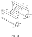
- the bottom surface of each end of cross member 160 is coped or notched as best shown in FIGS. 16 and 20, whereby each end of the cross member nests in a respective one of main members 131 at the inboard right-angle junction of web134 and bottom flange 136.
- Cross member 160 is secured to main members 131 by any suitable means such as welding or mechanical fastening, although a continuous weld 137 is preferred.
- a generally triangular-shaped suspension assembly mounting member 161 fits on each end of cross member 160 and nests in the appropriate one of main members 131, thereby obviating the need for two additional cross members to assist in the mounting of each axle/suspension system 150 of vehicle trailer 125, as was required in prior art trailer frames such as shown at 30 in FIGS. 1-7 and as described hereinabove.
- each suspension assembly mounting member 161 is formed of any suitable material such as steel, but could also be formed of aluminum. As best shown in FIG.
- mounting member 161 preferably is burned out, by plasma or laser cutting, of 5.59mm (220 inches) thick grade 50 common steel plate, although plates of other thicknesses are contemplated by the present invention.
- the generally rectangular-shape of the steel plate before reconfiguration into generally triangular-shaped mounting member 161 minimizes manufacturing waste.
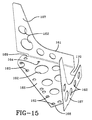
- a plurality of holes 162, 163 and 164 are formed in mounting member 161 by burning or punching, for reducing the weight of the member and promoting drainage (holes 162), for plug welding the member to the appropriate one of main members 131 (holes 163), and for bolting a component of axle/suspension system 150 thereto (holes 164), respectively.
- mounting member 161 Prior to mounting on trailer frame 130, the steel plate shown in FIG.14 is reconfigured along bend lines 165 so that mounting member 161 includes, after reconfiguration into a generally triangular shape, a horizontal mount base 166 and a pair of diagonally opposed vertically extending gussets 167. As best shown in FIGS.10-15 and 17-20, the coped or notched areas 168 and 169 enable gussets 167 to nest in the inboard facing generally U-shaped area defined by the inboard surface of main member web 134 and the bottom and top surfaces, respectively, of main member top flange 135 and main member bottom flange 136.
- Notches 168 and 169 also enable the outboard edge upper surface of mount base 166 to abut the bottom surface of main member bottom flange 136.
- the coped or notched area 170 in the inboard edge of mounting member 161 similarly enables the mounting member to fit on cross member 160.
- Mounting member 161 then is securely attached to main member 131 by plug welds 171 (FIG. 13) placed in plug weld holes 163 and a continuous weld 172 disposed along the interface of mounting member coped area 170 and cross member 160 (FIGS. 10, 12-13 and 17-20).
- Mounting member 161 is further secured in place by a continuous weld 173 disposed along the interface of each gusset 167 and main members 131 (FIGS. 10, 12 and 17-20).
- trailer frame 130 of the present invention supports front and rear axle/suspension systems 150A and 150B, respectively.
- each axle/suspension system 1 50A, B is suspended from trailer frame 130, but does not form an integral part thereof, only the major components of system 150 will be cited for aiding in the description of the environment in which the trailer frame of the present invention is useful.
- Each axle/suspension system 1 50A, B includes generally identical suspension assemblies 151 suspended from each hanger of the pair of hangers 133A, B, respectively.
- Each suspension assembly 151 includes a suspension beam 152 which is pivotally mounted on hanger 133 in a usual manner.
- An air spring 153 is suitably mounted on and extends between the upper surface of the rearwardmost end of suspension beam 152 and mount base 166 of suspension assembly mounting member 161. More particularly, and as best shown in FIGS. 8, 11-13, and 17 to 20, a front bolt 145A of air spring 153 extends upwardly through bolt hole 164 of mounting member mount base 166 and a nut 146 is threadably engaged therewith. A rear bolt 145B of air spring 153 extends through an opening 147 formed in a bracket 148 which is welded to a rear portion of suspension assembly mounting member 161, and a nut 146 is threadably engaged therewith to secure the air spring to the mount base.
- a shock absorber 154 extends between and is mounted on suspension beam 152 and hanger gusset 139.
- suspension assembly 151 Other components of suspension assembly 151, mentioned herein only for the sake of relative completeness, include an air brake 155 and a height control valve (not shown).
- An axle 157 extends between and is captured in the pair of suspension beams 152 of each axle/suspension system 150A, B.
- One or more wheels 158 are mounted on each end of axle 157.
- cross member/suspension system mounting assembly 132 which includes cross member 160 and suspension assembly mounting members 161 and which replaces and improves upon conventional multiple cross members 32 of prior art trailer frame designs. More particularly, trailer frame 130 of the present invention optimizes the structure and location of cross member/suspension system mounting assembly 132A, B for withstanding lateral, longitudinal, vertical and roll load conditions encountered by the trailer frame primarily during movement of vehicle trailer 125, yet reduces the overall weight of the trailer frame from that of prior art trailer frames by up to about 454 kg (100 pounds), and simplifies the structure of the trailer for easier assembly. More specifically, and as shown in prior art FIGS.
- prior art trailer frame designs typically include about thirty component parts to support a single axle/suspension system 50 which increases production and inventory expenses.
- the large number of parts makes installation difficult, time consuming, labor intensive and requires a certain level of skill and training for the installer.
- the total weight of all thirty of the installed parts can add up to approximately 160 kg (350 pounds).
- the new construction optimizes the ability of trailer frame 130 to withstand such lateral, longitudinal, vertical, and roll loads by utilizing improved cross member/suspension system mounting assembly 132 and furthermore provides for significant weight and manufacturing cost savings from prior art trailer frame designs due to a reduction in parts and associated labor required to assemble those parts.
- the plurality of cross members 32A to C and 32D to F of prior art trailer frame 30 are replaced by a pair of cross member/suspension system mounting assemblies 132A and 132B, respectively, to achieve such optimization.
- FIG. 1 front cross member/suspension system mounting assembly 132A since the structure and function of rear cross member/suspension system mounting assembly 132B is virtually identical, a single cross member/suspension system mounting assembly 132A replaces three separate cross members 32A through C. More specifically, the front and rear of each hanger 33A requires substantial support since the hangers in turn are assisting in supporting the entire axle/suspension system 50A.
- a pair of spaced-apart parallel cross members 32A and 32B assisted in supporting the front and rear portions, respectively, of hangers 33. Comparing and contrasting the present embodiment (FIGS.
- the front portion of mounting member 161 supports the front portion of hanger 133A
- cross member 160 generally supports the rear portion of hanger 133A.
- the present invention utilizes the rear portion of mounting member 161 to support air spring 153.
- Bracket 148 merely supplies additional stability to air spring 153.
- cross member/suspension system mounting assembly 132 of the present invention eliminates the need for additional stiffeners 41, gussets 47 and ribs 48 found in prior art trailer frame 30, which are all required to assist in supporting the relatively high vertical web 34 of main members 31.
- a pair of gussets 167 formed on each mounting member 161 serve this function in the trailer frame of the present invention. Also, the generally triangular design of mounting member 161 effects diagonal bracing of main member 131, which serves to reduce the degree of flex of the main members due to lateral loads by directing such loads to cross member 160 which is very efficient at dissipating twisting loads. Diagonally disposed gussets 167 also function to resist vertical and side loads. The large area of mount base 166, in combination with cross member 160, also stabilizes main member bottom flange 136.
- cross member/suspension system mounting assembly 132 even provides additional benefits. As shown in FIGS. 10, 12-13 and 16-20 welds 137, 138, 172, and 173 are continuous or uninterrupted, in stark contrast to the stop and start welds found in prior art trailer frames such as shown and described herein. Such continuous welds simply are less likely to crack than the interrupted welds commonly found in prior art trailer frames.
- cross member/suspension system mounting assembly 132A contains only eight parts as opposed to the thirty parts commonly found in prior art designs, thereby reducing the overall weight of about 160 kg (350 pounds) by nearly 36 kg (80 pounds).
- the simplified structure also reduces manufacturing costs of the trailer frame by lowering production, inventory and assembly costs.
- cross member/suspension system mounting assembly of the present invention can be utilized on trailer frames having more or less than the two axles illustrated and described herein.
- the improved cross member/suspension assembly mount for vehicle trailer frames is simplified, provides an effective, safe, inexpensive, and efficient mount which achieves all the enumerated objectives, provides for eliminating difficulties encountered with prior vehicle trailer frames, and solves problems and obtains new results in the art.
Landscapes
- Engineering & Computer Science (AREA)
- Mechanical Engineering (AREA)
- Chemical & Material Sciences (AREA)
- Combustion & Propulsion (AREA)
- Transportation (AREA)
- Vehicle Body Suspensions (AREA)
- Body Structure For Vehicles (AREA)
Abstract
Description
- The invention relates to vehicle trailers and in particular to frame-type vehicle trailers. More particularly, the invention is directed to a frame-type vehicle trailer which includes a pair of generally triangular-shaped members which form an assembly with a single cross member thereby eliminating a plurality of frame cross members, for more securely and efficiently supporting suspension assemblies suspended therefrom.
- Vehicle trailer frames and the axle/suspension systems suspended therefrom, including trailer frames for vans, reefers, tankers, dumps, lowbeds, flatbeds, platforms, and logging trailers, must be capable of reacting to roll moments, side loads, brake loads and other forces in order to safely and efficiently transport payloads or cargo. Since such forces act through the axle/suspension systems of the trailer, mounting of the axle/suspension systems to the trailer frame is of critical importance.
- Flatbed and platform trailers in particular, due to their lack of a stiff upper structure and/or heavy duty characteristics such as is found in the other above-described types of vehicle trailers, are subject to greater deflections under load which can cause stress at rigid areas of the trailer. More specifically, such rigid areas are created by the trailer frame cross member/suspension assembly mounts. More particularly, a typical flatbed or platform structure typically consists of a pair of longitudinally extending, spaced-apart parallel main members, which are interconnected by three perpendicularly extending cross members for each axle/suspension system suspended from the trailer frame. The cross members typically are welded to the main members to form an integral rigid ladder-like trailer frame structure. A plurality of web stiffeners also are conventionally added to stabilize the relatively tall thin web of each main member, which usually is an I-beam, thus adding additional rigidity to the trailer frame structure.
- Such a conventional flatbed or platform trailer assembly as described immediately above, while having years of utility in the field, fails to operate optimally for various reasons. More particularly, these types of trailer assemblies, although having certain rigid areas as noted hereinabove, generally display relatively flexible structures. For example, when such a trailer frame is subjected to lateral loads resulting from a sharp turn, the ladder-like structure of the frame deflects into a parallelogram-like structure. More specifically, these lateral loads actually combine with vertical, longitudinal and roll loads to produce a twisted parallelogram structure. In such a relatively flexible structure, the trailer frame main members and cross members actually distort into S-shaped structures. However, at the certain rigid areas of the trailer frame, namely, the interconnection areas of the cross members to the main members, the trailer frame is prevented from distorting resulting in high stress at such interconnections.
- Aggravating the above-described prior art problem are the discontinuities in frame structure and interruptions of welds caused by the non-corresponding size of the suspension assembly hangers and the frame main members. More particularly, the hanger for each of the pair of suspension assemblies of each axle/suspension system typically is wider than the bottom flange of the respective main member I-beam from which each hanger depends. This extra width of each hanger relative to the bottom flange of its respective I-beam typically extends inboardly from the I-beams. So that the cross members disposed above the hangers can contact the upper surface of the hangers yet still nest in the I-beams to form a rigid mount for the suspension assemblies, the ends of each cross member are notched or coped out around the bottom flange of each I-beam. Alternatively, a spacer is used to fill the gap between the inboardly extending additional width of each hanger and the bottom surface of the cross members. In either case, the welds securing each hanger to the trailer frame structure must be interrupted at the junction of the bottom flange of the I-beam and the cross members or the spacer.
- The above-described interrupted welds combined with the high stress inflicted on the rigid connection area of the cross members to the main members can result in cracks in the trailer frame main members or cross members, or in the welds at the nesting junction of each of the cross member ends in the web of its respective I-beam main member. Cracks further can occur in welds at the interface of each end of the cross members to its respective hanger or the air-spring mounting plate.
- Moreover, assembly of a prior art trailer frame, including suspension assembly mounts, during manufacture of the vehicle trailer is difficult, time consuming, labor intensive, and requires a certain level of skill and training. There are typically about thirty component parts needed to mount a single axle/suspension system, which are expensive to produce and inventory. In addition, the weight of those approximately thirty component parts can total about 160 kg (350 pounds).
- The above-described problems associated with conventional or prior art vehicle trailer frames are addressed by the trailer frame cross member/suspension assembly mount proposed later herein. The present proposed provides support against the twisting, parallelogram and S-shaped deflections typically caused by vertical, lateral, longitudinal, and roll loading, by replacing a plurality of cross members with a cross member/suspension assembly mount comprising a single cross member having a generally triangular-shaped structure attached to each of its ends, and also provides for an easy to assemble, simple and lightweight structure.
- Other prior art disclosures include US 2700551, showing the cross-members in the form of channels projecting right through the webs of the main side I-beams via correspondingly-shaped slots, into which they are then welded. In one embodiment the cross-members projecting end is braced to the outside of the I-beams web by a trapezoidal support sheet which is welded on and which has a suspension spring bracket on its underside.
- Preferred aims herein include the following
a vehicle trailer frame cross member/suspension assembly mount having significantly reduced weight from that found in prior art trailer frame cross-member/suspension assembly mounts, yet having good capability for withstanding combined lateral, longitudinal, roll and vertical loads;
a vehicle trailer frame cross member/suspension assembly mount which has a reduced number of components and therefore is simpler in structure and easier to assemble than prior art trailer frame cross member/suspension assembly mounts;
a vehicle trailer frame cross member/suspension assembly mount that is free of weld and structural discontinuities. - In one aspect, as set out in
claim 1, the present invention provides a vehicle trailer frame including: - a) a pair of elongate spaced-apart parallel main members and
- b) at least one cross member/suspension system mounting assembly including:
- (i) a cross member having a pair of ends, said cross member extending between said main members, and each of said cross member ends being attached to a respective one of said main members, and
- (ii) a pair of suspension assembly mounting members each being attached to a respective one of the cross member ends and to the respective main member, so that an axle/suspension system can be mounted depending from said cross member/suspension system mounting assembly;
- In another aspect, as set out in claim 9, the present invention provides a method of assembling a vehicle trailer frame, including the steps of:
- (a) positioning a cross member having a pair of ends to extend between a pair of elongated spaced-apart parallel main members;
- (b) attaching each of said cross member ends to a respective one of the main members with a continuous weld;
- (c) providing a pair of suspension assembly mounting members each formed by reconfiguring a flat plate to provide a horizontal generally triangular base joined to vertically extending diagonally-opposed spaced-apart gussets;
- (d) attaching each of the suspension assembly mounting members to a respective one of said cross member ends and to a respective one of said main members by continuous welds;
- (e) attaching a depending hanger to each of the suspension assembly mounting members using a continuous weld, and
- (f) attaching a depending axle/suspension system to said suspension assembly mounting members and said hangers.
- Further details of the invention and its differences from known constructions are now explained by way of examples, with reference to the accompanying drawings in which:
- FIG. 1 is a fragmentary top plan view of a prior art flatbed or platform trailer, with the trailer deck represented by broken lines;
- FIG. 2 is a fragmentary side view of the prior art trailer shown in FIG. 1, but with the location of the wheels and hidden parts represented by broken lines;
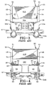
- FIG. 3 is an enlarged fragmentary front view of the prior art trailer, looking in the direction of lines 3-3 of FIG 1;
- FIG. 4 is an enlarged fragmentary rear view of the prior art trailer, looking in the direction of lines 4-4 of FIG 1;
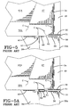
- FIG. 5 is an enlarged view of a portion of the prior art trailer looking in the direction of lines 5-5 of FIG. 2, and showing the interruption of welds at various junctions of the cross member, main member, hanger and hanger gusset, and structural cracks resulting therefrom;
- FIG. 5A is a view similar to FIG. 5, but showing a prior art embodiment wherein the cross member is free of a coped end at its junction to the main member, with a spacer inserted between the hanger and hanger gusset and the cross member;
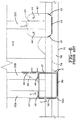
- FIG. 6 is an enlarged fragmentary view looking in the direction of lines 6-6 of FIG. 2, with certain components of the suspension assembly removed and hidden parts represented by broken lines, and showing the interrupted welding pattern at various junctions of the cross members, main member, hanger, hanger gusset, and the air spring mounting plate;
- FIG. 7 is an enlarged fragmentary view looking in the direction of lines 7-7 of FIG. 1, with certain components of the suspension assembly removed, hidden parts represented by broken lines and portions broken away, and showing the interrupted welding pattern at the hanger to main member junction;
- FIG. 7A is a schematic representation of the prior art flatbed or platform trailer shown in FIG. 1, showing some of the loads acting on the frame of the trailer during an event such as a sharp turn and the resultant distortion of the frame into a generally S-shaped structure;
- FIG. 8 is a fragmentary top plan view of a flatbed or platform-type trailer incorporating the cross member/suspension assembly mount of the present invention, with the trailer deck and hidden parts represented by broken lines;
- FIG. 9 is a fragmentary side view of the trailer shown in FIG. 8, but with the location of the wheels and hidden parts represented by broken lines;
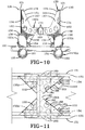
- FIG. 10 is an enlarged fragmentary front view of the trailer of the present invention, looking in the direction of lines 10-10 of FIG. 9, and showing the continuous or uninterrupted welds at various junctions of the cross member/suspension system mounting assembly, main members, hangers, and hanger gussets;
- FIG. 1 is an enlarged fragmentary top view looking in the direction of lines 11-11 of FIG. 9, with parts of the axle/suspension system removed, portions broken away and hidden parts represented by broken lines;
- FIG. 12 is an enlarged fragmentary rear view looking in the direction of lines 12-12 of FIG. 9, with portions of the suspension system removed, and showing the continuous or uninterrupted welds at various junctions of the cross member/suspension system mounting assembly and main members;
- FIG. 13 is an enlarged fragmentary bottom view looking in the direction of lines 13-13 of FIG. 9, with parts of the axle/suspension system removed and hidden parts represented by broken lines, and showing the continuous or uninterrupted pattern of welding at various junctions of the cross member/suspension system mounting assembly, main members, hangers, and hanger gussets;
- FIG. 14 is a top plan view of one of the two suspension assembly mounting members of the cross member/suspension system mounting assembly of the present invention, as it appears after being burned out of a plate but before reconfiguration and assembly.
- FIG. 15 is a perspective view of the suspension assembly mounting member shown in FIG. 14, and showing its reconfiguration for incorporation into a trailer frame;
- FIG. 16 is a fragmentary perspective bottom view of a trailer frame, showing only the main members and the cross member of the cross member/suspension system mounting assembly of the present invention incorporated into the trailer frame;
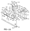
- FIG. 17 is a view similar to FIG. 16, but showing the pair of suspension assembly mounting members of the cross member/suspension system mounting assembly of the present invention incorporated into the trailer frame;
- FIG. 18 is a view similar to FIG. 17, but showing the hangers and air spring brackets of the axle/suspension system mounted on the suspension assembly mounting members;
- FIG. 19 is another bottom perspective view similar to FIGS. 17 and 18, but showing the air springs of the axle/suspension system mounted on the suspension assembly mounting members; and
- FIG. 20 is a fragmentary top perspective view of the assembly shown in FIG. 19.
- Similar numerals refer to similar parts throughout the drawings.
- A prior art vehicle flatbed or platform trailer is indicated generally at 25 and is shown in FIG. 1.
Trailer 25 includes adeck 37, atrailer frame 30 for supportingdeck 37, a pair ofmain members 31, a plurality ofcross members 32A through F, and front and rear pairs ofhangers suspension systems - Specifically, each
main member 31 is an elongated, generally I-shaped beam made of a metal such as steel or other suitable material. More particularly, each I-shapedbeam 31 includes avertical web plate 34 which interconnects in a spaced-apart relationship top and bottomhorizontal flanges Main members 31 are connected to each other in spaced-apart parallel relationship bycross members 32A through F, which extend between and are perpendicular tomain members 31. Each ofcross members 32A, B, D, and E, is a generally C-shaped beam made of a metal such as steel or other suitable material. The open portions ofcross members cross members Cross members main members 31 at the inboard right-angle junction ofweb 34 andbottom flange 36, and is secured therein preferably by welding (FIGS. 3, 4 and 5). Each hanger 33 includes an integrally formed inboardly extendinggusset 39, and is attached to the bottom surface ofbottom flange 36 of a respective one ofmain members 31 bywelds 38, as best shown in FIGS. 5 to 7. It can also be appreciated, as shown in FIGS. 1, 3, and 5 to 6, that each hanger 33 extends inboardly beyond the inboardmost edge ofbottom flange 36, and the inboardly extending portion of hanger 33 andintegral gusset 39 are each secured to the bottom surface of a certain pair ofcross members 32A and B or 32D and E, by welds 40. As shown in FIG. 5A, if it is desired to refrain from forming a copedarea 60 on each end of each cross member 32, then aspacer 61 must be used to achieve contact between the inboard portion of hanger 33 and the cross member. In such an arrangement, the height ofgusset 39 is increased so that the length ofspacer 61 can be minimized. However, the outboard end ofgusset 39 is formed with a copedarea 62 to accommodatespacer 61. As with the embodiment shown in FIG. 5, welds 40 are used to interconnect the arrangement of parts. - As mentioned hereinabove, and as best shown in FIGS. 1 through 4, prior
art trailer frame 30 supports front and rear axle/suspension systems suspension system 50A, B is suspended fromtrailer frame 30, but does not form an integral part thereof, only the major components of system 50 will be cited for aiding in the description of the environment in which the prior art trailer frame operates. Each axle/suspension system 50A, B, includes generallyidentical suspension assemblies 51 suspended from each hanger of the pair ofhangers 33A, B, respectively. Eachsuspension assembly 51 includes asuspension beam 52, which is pivotally mounted on hanger 33 in a usual manner. Anair spring 53 is suitably mounted on and extends between the upper surface of the rearwardmost end ofsuspension beam 52 andmain member 31 at a location directly beneath a certain one of thecross members 32C, F. More specifically, an airspring mounting plate 42 is securely mounted on the bottom surface ofbottom flange 36 of I-beam 31 and the bottom surface ofcertain cross member 32C, F by welds 43 (FIG. 6). Mountingplate 42 is formed with a pair ofopenings 44, which receivebolts 45 attached to the upper end ofair spring 53.Nuts 46 are threadably engaged withair spring bolts 45 for securingair spring 53 to mountingplate 42. Ashock absorber 54 extends between and is mounted onsuspension beam 52 andhanger gusset 39. Other components ofsuspension assembly 51, mentioned herein only for the sake of relative completeness, include anair brake 55 and a height control valve (not shown). Anaxle 57 extends between and is captured in the pair of suspension beams 52 of each axle/suspension system 50A, B. One ormore wheels 58 are mounted on each end ofaxle 57. - As best shown in FIGS. 1-4 and 7, front and
rear stiffening plates 41A and B, respectively, extend between and are suitably attached, such as by welding, to the upper surface of a certain one ofcross members 32C, F, andweb 34 andtop flange 35 of eachmain member 31. Agusset 47 is attached by any suitable means such as welding, to each end of each ofcross members 32A, B, D, and E, and to the inboard lower surface oftop flange 35 and the inboard surface ofweb 34 of a respective one of I-beams 31. In addition, a rectangular-shapedrib 48 is attached to theoutboard web surface 34 and the lower surface oftop flange 35 and the upper surface ofbottom flange 36 ofmain member 31 by any suitable means such as welding, and is aligned with a respective one of thegussets 47. Stiffeningplates 41,gussets 47 andribs 48 are all required to maintain the structural integrity oftrailer frame 30, since the flatbed orplatform deck 37 of this type ofvehicle trailer 25, combined with the relatively large vertical height of I-beams 31, is not stiff enough to protect the frame from the various deflections under load thattrailer 25 is subjected to during operation, with such loads being represented in FIG. 7A. Such loads can cause unwanted stress and possible cracking of welds at the rigid frame areas such as at the junction of various frame components and suspension assembly mounting structures, namely, 1-beams 31, cross members 32, hangers 33, and mounting plates 42 (FIGS. 5-6). However,plates 41,gussets 47 andribs 48 add unwanted parts and weight totrailer frame 30. - An improved trailer frame for a vehicle flatbed or
platform trailer 125 embodying the present invention is indicated generally at 130 and is shown in FIGS. 8 and 9. Although thistrailer frame 130 is similar in some respects to priorart trailer frame 30 described in detail hereinabove and shown in FIGS. 1 through 7,trailer frame 130 is different thantrailer frame 30 in certain respects, thereby contributing to the improved performance of the trailer frame over prior art trailer frames. The structural and resulting performance differences between trailer frames 130 and 30 will be described in detail below.Trailer 125 includes adeck 177, atrailer frame 130 for supportingdeck 177, a pair ofmain members 131, front and rear cross member/suspensionsystem mounting assemblies hangers suspension systems - Specifically, each
main member 131 is an elongated, generally I-shaped beam made of a metal such as steel or other suitable material. However, it is understood that the shape ofmain member 131 could be different, such as a C-shaped channel, without affecting the overall concept of the present invention. More particularly, each I-shapedbeam 131 includes avertical web plate 134, which interconnects in a spaced-apart relationship top and bottomhorizontal flanges Main members 131 are connected to each other in spaced-apart parallel relationship by cross member/suspensionsystem mounting assemblies 132A, B which extend between the main members. - In accordance with one of the main features of the present invention, and as best shown in FIGS. 10 through 13, each cross member/suspension
system mounting assembly 132 includes across member 160 which extends between and is perpendicular tomain members 131.Cross member 160 preferably is generally square or rectangular-shaped, however other cross-sectional shapes are contemplated by the present invention, such as an inverted U-shaped channel. The bottom surface of each end ofcross member 160 is coped or notched as best shown in FIGS. 16 and 20, whereby each end of the cross member nests in a respective one ofmain members 131 at the inboard right-angle junction of web134 andbottom flange 136.Cross member 160 is secured tomain members 131 by any suitable means such as welding or mechanical fastening, although acontinuous weld 137 is preferred. - In accordance with another of the important features of the present invention, a generally triangular-shaped suspension
assembly mounting member 161 fits on each end ofcross member 160 and nests in the appropriate one ofmain members 131, thereby obviating the need for two additional cross members to assist in the mounting of each axle/suspension system 150 ofvehicle trailer 125, as was required in prior art trailer frames such as shown at 30 in FIGS. 1-7 and as described hereinabove. More specifically, each suspensionassembly mounting member 161 is formed of any suitable material such as steel, but could also be formed of aluminum. As best shown in FIG. 14, mountingmember 161 preferably is burned out, by plasma or laser cutting, of 5.59mm (220 inches) thick grade 50 common steel plate, although plates of other thicknesses are contemplated by the present invention. The generally rectangular-shape of the steel plate before reconfiguration into generally triangular-shaped mountingmember 161 minimizes manufacturing waste. A plurality ofholes member 161 by burning or punching, for reducing the weight of the member and promoting drainage (holes 162), for plug welding the member to the appropriate one of main members 131 (holes 163), and for bolting a component of axle/suspension system 150 thereto (holes 164), respectively. Prior to mounting ontrailer frame 130, the steel plate shown in FIG.14 is reconfigured alongbend lines 165 so that mountingmember 161 includes, after reconfiguration into a generally triangular shape, ahorizontal mount base 166 and a pair of diagonally opposed vertically extendinggussets 167. As best shown in FIGS.10-15 and 17-20, the coped or notchedareas gussets 167 to nest in the inboard facing generally U-shaped area defined by the inboard surface ofmain member web 134 and the bottom and top surfaces, respectively, of mainmember top flange 135 and mainmember bottom flange 136.Notches mount base 166 to abut the bottom surface of mainmember bottom flange 136. The coped or notchedarea 170 in the inboard edge of mountingmember 161 similarly enables the mounting member to fit oncross member 160. Mountingmember 161 then is securely attached tomain member 131 by plug welds 171 (FIG. 13) placed in plug weld holes 163 and acontinuous weld 172 disposed along the interface of mounting member copedarea 170 and cross member 160 (FIGS. 10, 12-13 and 17-20). Mountingmember 161 is further secured in place by acontinuous weld 173 disposed along the interface of eachgusset 167 and main members 131 (FIGS. 10, 12 and 17-20). The advantages of cross member/suspensionsystem mounting assembly 132 over prior art cross members 32 will be described in detail hereinbelow. - As mentioned hereinabove, and as best shown in FIGS. 8, 9, 10 and 12,
trailer frame 130 of the present invention supports front and rear axle/suspension systems suspension system 1 50A, B is suspended fromtrailer frame 130, but does not form an integral part thereof, only the major components of system 150 will be cited for aiding in the description of the environment in which the trailer frame of the present invention is useful. Each axle/suspension system 1 50A, B includes generallyidentical suspension assemblies 151 suspended from each hanger of the pair ofhangers 133A, B, respectively. Eachsuspension assembly 151 includes asuspension beam 152 which is pivotally mounted onhanger 133 in a usual manner. Anair spring 153 is suitably mounted on and extends between the upper surface of the rearwardmost end ofsuspension beam 152 and mountbase 166 of suspensionassembly mounting member 161. More particularly, and as best shown in FIGS. 8, 11-13, and 17 to 20, afront bolt 145A ofair spring 153 extends upwardly throughbolt hole 164 of mountingmember mount base 166 and anut 146 is threadably engaged therewith. Arear bolt 145B ofair spring 153 extends through anopening 147 formed in abracket 148 which is welded to a rear portion of suspensionassembly mounting member 161, and anut 146 is threadably engaged therewith to secure the air spring to the mount base. Ashock absorber 154 extends between and is mounted onsuspension beam 152 andhanger gusset 139. Other components ofsuspension assembly 151, mentioned herein only for the sake of relative completeness, include anair brake 155 and a height control valve (not shown). Anaxle 157 extends between and is captured in the pair ofsuspension beams 152 of each axle/suspension system 150A, B. One ormore wheels 158 are mounted on each end ofaxle 157. - As discussed above, one of the most important features of the present invention is cross member/suspension
system mounting assembly 132, which includescross member 160 and suspensionassembly mounting members 161 and which replaces and improves upon conventional multiple cross members 32 of prior art trailer frame designs. More particularly,trailer frame 130 of the present invention optimizes the structure and location of cross member/suspensionsystem mounting assembly 132A, B for withstanding lateral, longitudinal, vertical and roll load conditions encountered by the trailer frame primarily during movement ofvehicle trailer 125, yet reduces the overall weight of the trailer frame from that of prior art trailer frames by up to about 454 kg (100 pounds), and simplifies the structure of the trailer for easier assembly. More specifically, and as shown in prior art FIGS. 5 through 7, the design of priorart trailer frame 30 including a plurality of cross members 32 for each axle/suspension system 50, requires many weld starts and stops. Such interrupted welds maketrailer frame 30 more susceptible to cracks C inmain members 31 or cross members 32 caused by the lateral, longitudinal, vertical, and roll load conditions that the trailer frame encounters during operation (see FIG. 7A). Cracks also can occur at the cross member to main member interface due to flexible twisting of the trailer frame at the stiff area created by the cross members at the suspension assemblies. Cracks also occur in this area due to side-to-side movement of the main members. Finally, cracks also can occur at the interface of the cross member, hanger, and/or air spring mounting plate with mainmember bottom flange 36. Moreover, prior art trailer frame designs typically include about thirty component parts to support a single axle/suspension system 50 which increases production and inventory expenses. In addition, the large number of parts makes installation difficult, time consuming, labor intensive and requires a certain level of skill and training for the installer. Finally, the total weight of all thirty of the installed parts can add up to approximately 160 kg (350 pounds). - In comparison and contrast, the new construction optimizes the ability of
trailer frame 130 to withstand such lateral, longitudinal, vertical, and roll loads by utilizing improved cross member/suspensionsystem mounting assembly 132 and furthermore provides for significant weight and manufacturing cost savings from prior art trailer frame designs due to a reduction in parts and associated labor required to assemble those parts. The plurality ofcross members 32A to C and 32D to F of priorart trailer frame 30 are replaced by a pair of cross member/suspensionsystem mounting assemblies system mounting assembly 132A since the structure and function of rear cross member/suspensionsystem mounting assembly 132B is virtually identical, a single cross member/suspensionsystem mounting assembly 132A replaces threeseparate cross members 32A through C. More specifically, the front and rear of eachhanger 33A requires substantial support since the hangers in turn are assisting in supporting the entire axle/suspension system 50A. Heretofore, such as in prior art trailer frame 30 (FIGS. 1 and 2) a pair of spaced-apartparallel cross members member 161 supports the front portion ofhanger 133A, andcross member 160 generally supports the rear portion ofhanger 133A. Moreover, rather than using still anothercross member 32C and mountingplate 42 to supportair spring 153, the present invention utilizes the rear portion of mountingmember 161 to supportair spring 153.Bracket 148 merely supplies additional stability toair spring 153. It should also be noted that cross member/suspensionsystem mounting assembly 132 of the present invention eliminates the need foradditional stiffeners 41,gussets 47 andribs 48 found in priorart trailer frame 30, which are all required to assist in supporting the relatively highvertical web 34 ofmain members 31. A pair ofgussets 167 formed on each mountingmember 161 serve this function in the trailer frame of the present invention. Also, the generally triangular design of mountingmember 161 effects diagonal bracing ofmain member 131, which serves to reduce the degree of flex of the main members due to lateral loads by directing such loads to crossmember 160 which is very efficient at dissipating twisting loads. Diagonally disposedgussets 167 also function to resist vertical and side loads. The large area ofmount base 166, in combination withcross member 160, also stabilizes mainmember bottom flange 136. - The structure of cross member/suspension
system mounting assembly 132 even provides additional benefits. As shown in FIGS. 10, 12-13 and 16-20welds - Finally, the improved structure of cross member/suspension
system mounting assembly 132A contains only eight parts as opposed to the thirty parts commonly found in prior art designs, thereby reducing the overall weight of about 160 kg (350 pounds) by nearly 36 kg (80 pounds). The simplified structure also reduces manufacturing costs of the trailer frame by lowering production, inventory and assembly costs. - It is understood and contemplated that the cross member/suspension system mounting assembly of the present invention can be utilized on trailer frames having more or less than the two axles illustrated and described herein.
- Accordingly, the improved cross member/suspension assembly mount for vehicle trailer frames is simplified, provides an effective, safe, inexpensive, and efficient mount which achieves all the enumerated objectives, provides for eliminating difficulties encountered with prior vehicle trailer frames, and solves problems and obtains new results in the art.
- In the foregoing description, certain terms have been used for brevity, clearness and understanding; but no unnecessary limitations are to be implied therefrom beyond the requirements of the prior art, because such terms are used for descriptive purposes and are intended to be broadly construed.
- Moreover, the description and illustration of the invention is by way of example, and the scope of the invention is not limited to the exact details shown or described, but only by the appended claims.
each suspension assembly mounting member includes a horizontally disposed generally triangular base joined to a pair of spaced-apart diagonally-opposed vertically-extending gussets which are joined to and extend up the respective main member.
Claims (11)
- A vehicle trailer frame including:a) a pair of elongate spaced-apart parallel main members (131) andb) at least one cross member/suspension system mounting assembly (132) including:characterized in that(i) a cross member (160) having a pair of ends, said cross member extending between said main members, and each of said cross member ends being attached to a respective one of said main members (131), and(ii) a pair of suspension assembly mounting members (161) each being attached to a respective one of the cross member ends and to the respective main member (131), so that an axle/suspension system can be mounted depending from said cross member/suspension system mounting assembly;
each suspension assembly mounting member (161) includes a horizontally disposed generally triangular base (166) joined to a pair of spaced-apart diagonally-opposed vertically-extending gussets (167) which are joined to and extend up the respective main member. - A vehicle trailer frame according to claim 1 in which a plurality of holes (162,163,164) are formed in the base (166) and in the gussets (167) of each suspension assembly mounting member (161).
- A vehicle trailer frame according to claim 1 or claim 2 in which the cross member (160) is perpendicular to said main members (131).
- A vehicle trailer frame according to any one of the preceding claims in which each of the cross member ends nests into the side of and is attached by a continuous weld (137) to a respective one of the main members (131), and in which each of the suspension assembly mounting members (161) fits on said cross member (160) and has its gussets (167) nested into the side of the respective main member (131), and is attached to said cross member (160) and said main member (131) by continuous welds (172,173).
- A vehicle trailer frame according to any one of the preceding claims in which a hanger (133) is mounted by a continuous weld (138) to depend from each of the suspension assembly mounting members (161).
- A vehicle trailer frame according to claim 5 in which an air spring (153) is mounted on and depends from each of the suspension assembly mounting members (161).
- A vehicle trailer frame according to claim 5 in which a suspension assembly (150) is mounted on the hanger (133) of each of the suspension assembly mounting members, and an axle (157) extends between and is captured in the pair of suspension assemblies.
- A vehicle trailer frame according to any one of the preceding claims in which each suspension assembly mounting member (161) consists of a piece of steel plate bent to form the gussets (167) extending up from edges of the triangular base (166).
- A method of assembling a vehicle trailer frame, including the steps of:(a) positioning a cross member (160) having a pair of ends to extend between a pair of elongated spaced-apart parallel main members (131);(b) attaching each of said cross member ends to a respective one of the main members (131) with a continuous weld (137);(c) providing a pair of suspension assembly mounting members (161) each formed by reconfiguring a flat plate to provide a horizontal generally triangular base (166) joined to vertically extending diagonally-opposed spaced-apart gussets (167);(d) attaching each of the suspension assembly mounting members (161) to a respective one of said cross member ends and to a respective one of said main members (131) by continuous welds (172, 173);(e) attaching a depending hanger (133) to each of the suspension assembly mounting members (161) using a continuous weld, and(f) attaching a depending axle/suspension system (150) to said suspension assembly mounting members (161) and said hangers (133).
- A method according to claim 9 in which the cross member (160) is perpendicular to said main members (131).
- A method according to claim 10 in which each of the cross member ends is nested into a respective one of the main members (131), and each of the suspension assembly mounting members (161) is fitted onto said cross member (160) and nests into a respective one of said main members (131).
Applications Claiming Priority (3)
| Application Number | Priority Date | Filing Date | Title |
|---|---|---|---|
| US81893 | 1998-05-20 | ||
| US09/081,893 US6213507B1 (en) | 1998-05-20 | 1998-05-20 | Vehicle trailer frame cross member/suspension assembly mount |
| PCT/US1999/010663 WO1999059830A1 (en) | 1998-05-20 | 1999-05-14 | Vehicle trailer frame cross member/suspension assembly mount |
Publications (2)
| Publication Number | Publication Date |
|---|---|
| EP1077818A1 EP1077818A1 (en) | 2001-02-28 |
| EP1077818B1 true EP1077818B1 (en) | 2006-04-19 |
Family
ID=22167088
Family Applications (1)
| Application Number | Title | Priority Date | Filing Date |
|---|---|---|---|
| EP99923053A Expired - Lifetime EP1077818B1 (en) | 1998-05-20 | 1999-05-14 | Vehicle trailer frame cross member/suspension assembly mount |
Country Status (8)
| Country | Link |
|---|---|
| US (1) | US6213507B1 (en) |
| EP (1) | EP1077818B1 (en) |
| AT (1) | ATE323613T1 (en) |
| AU (1) | AU749562B2 (en) |
| CA (1) | CA2330874C (en) |
| DE (1) | DE69930930T2 (en) |
| MX (1) | MXPA00011233A (en) |
| WO (1) | WO1999059830A1 (en) |
Families Citing this family (25)
| Publication number | Priority date | Publication date | Assignee | Title |
|---|---|---|---|---|
| US7559400B2 (en) | 1997-01-31 | 2009-07-14 | Aloha, Llc | Low profile chassis and suspension |
| US6398251B1 (en) | 1997-01-31 | 2002-06-04 | Dallas Smith Corporation | Axleless vehicle suspension system |
| US6652020B2 (en) * | 2002-04-09 | 2003-11-25 | Norco Industries, Inc. | Reinforcing bracket for trailer-frame butt joints |
| US7144041B2 (en) * | 2002-07-12 | 2006-12-05 | East Manufacturing Corporation | Aluminum hanger and hanger assembly |
| US6890003B2 (en) * | 2002-07-12 | 2005-05-10 | East Manufacturing Corporation | Suspension subframe assembly |
| US6966568B2 (en) * | 2003-02-12 | 2005-11-22 | Arvinmeritor Technology, Llc | Multi-function bracket for an air suspension |
| US7017888B2 (en) * | 2003-09-05 | 2006-03-28 | Arvinmeritor Technology Llc | Attachment arrangement for a composite leaf spring which accommodates longitudinal movement through shear displacement |
| US7419146B2 (en) * | 2003-09-05 | 2008-09-02 | Arvinemeritor Technology, Llc | Composite leaf spring geometry with an interlocking interface |
| US6991223B2 (en) * | 2003-09-05 | 2006-01-31 | Arvinmeritor Technology Llc | Composite leaf spring having an arcuate attachment arrangement for vehicle mounting |
| US7198298B2 (en) * | 2003-10-15 | 2007-04-03 | Hendrickson Usa, L L C | Movable subframe for semi-trailers |
| WO2005039900A2 (en) | 2003-10-24 | 2005-05-06 | Aloha, Llc | Suspensions for low floor vehicles |
| US7445220B2 (en) | 2004-02-06 | 2008-11-04 | Daimler Trucks North America Llc | Vehicle axle apparatus |
| US7559578B2 (en) * | 2004-10-18 | 2009-07-14 | Workhorse Custom Chassis, Llc | Vehicle chassis assembly |
| US7549660B2 (en) * | 2005-02-01 | 2009-06-23 | Hendrickson Usa, L.L.C. | Frame or subframe for tractor-trailers |
| US20070145702A1 (en) * | 2005-09-16 | 2007-06-28 | Booher Howard D | Trailer suspension with aluminum components |
| DE102006041664A1 (en) * | 2006-09-06 | 2008-03-27 | Daimler Ag | Carrier arrangement for attachment of rear axle arrangement of lorry to vehicle frame, has cross member carrier part extending in distance to axial arrangement approximately to height of frame longitudinal carriers of vehicle frame |
| US7681919B2 (en) * | 2007-03-30 | 2010-03-23 | Caterpillar Inc. | Diffuser plate for connecting a rigid structure to a flexible structure and machine using same |
| US20090200836A1 (en) * | 2008-02-12 | 2009-08-13 | Aaron Alls | Gusseted torsion system for an open frame vehicle |
| US8006990B1 (en) * | 2008-12-15 | 2011-08-30 | Reinke Manufacturing Co., Inc. | Spring hanger and method for attachment |
| CA2714255A1 (en) | 2009-09-01 | 2011-03-01 | Timbren Industries Inc. | Suspension mechanism |
| CA2835223C (en) | 2011-06-07 | 2015-03-24 | Hendrickson Usa, L.L.C. | Slider box for a heavy-duty vehicle |
| DE102012013148A1 (en) * | 2012-07-03 | 2014-01-09 | Zf Friedrichshafen Ag | Motor vehicle with a vehicle frame |
| EP3019358A4 (en) * | 2013-07-12 | 2017-04-26 | Hendrickson USA, L.L.C. | Axle brake bracket for thin-wall axle |
| US10994782B2 (en) * | 2018-11-13 | 2021-05-04 | Western Trailer Co. | Method and apparatus for attaching crossmembers to a pair of flanged beams |
| CA3254127A1 (en) | 2022-04-05 | 2023-10-12 | Hendrickson Usa, L.L.C. | Heavy-duty vehicle subframe with battery storage structure |
Family Cites Families (22)
| Publication number | Priority date | Publication date | Assignee | Title |
|---|---|---|---|---|
| US1314498A (en) | 1919-09-02 | Traii | ||
| US1372699A (en) * | 1921-03-29 | Automobile frame and spring | ||
| US788108A (en) | 1904-08-11 | 1905-04-25 | Jones Corbin Automobile Company | Vehicle running-gear. |
| US1349589A (en) | 1916-11-20 | 1920-08-17 | Cadillac Motor Car Company | Motor-vehicle |
| US1468522A (en) * | 1919-01-06 | 1923-09-18 | Willys Overland Co | Support for controlled mechanism |
| US2119193A (en) | 1933-04-22 | 1938-05-31 | Clarence W Avery | Vehicle body and chassis construction |
| GB612287A (en) | 1946-05-23 | 1948-11-10 | Standard Pressed Steel Co | Improvements in or relating to vehicle structures |
| US2700551A (en) | 1948-10-01 | 1955-01-25 | Daimler Benz Ag | Welded frame, especially for motor vehicles |
| US2707110A (en) * | 1949-11-14 | 1955-04-26 | William W Eisenhauer | Fluid pressure spring suspension for vehicles |
| GB1150002A (en) | 1966-06-10 | 1969-04-30 | Boden Trailers Ltd | Improvements in or relating to Vehicle Chassis |
| US3510149A (en) | 1967-10-04 | 1970-05-05 | John E Raidel | Adjustable air suspension |
| US3664679A (en) | 1970-01-22 | 1972-05-23 | Dale H Hille Co | Stabilizing device for trucks |
| DE2124547A1 (en) | 1970-05-28 | 1971-12-02 | Neville Industries (Mansfield) Ltd., Mansfield, Nottingham (Großbritannien) | Construction element |
| NL8800027A (en) | 1988-01-07 | 1989-08-01 | Weweler Nv | CONNECTION STRUCTURE FOR CONNECTING A SUSPENSION AXLE SUSPENSION TO A VEHICLE FRAME. |
| JPH02151578A (en) | 1988-11-30 | 1990-06-11 | Mitsubishi Motors Corp | Under carriage frame for truck |
| US5114183A (en) | 1990-09-19 | 1992-05-19 | Coachmen Industries, Inc. | Recreational vehicle frame |
| US5127668A (en) * | 1991-01-24 | 1992-07-07 | Raidel John E | Torque beam with clamped mono-pivot bushing and flexible axle seat |
| US5335932A (en) * | 1992-06-26 | 1994-08-09 | Nai Neway, Inc. | Apparatus for mounting a trailing arm air suspension to a sliding frame |
| US5393096A (en) | 1993-03-02 | 1995-02-28 | Nai Neway, Inc. | Suspension frame bracket |
| US5378006A (en) | 1993-07-21 | 1995-01-03 | Reyco Industries, Inc. | Slider suspension for semi-trailers |
| US5720489A (en) | 1995-05-17 | 1998-02-24 | The Boler Company | Movable subframe for tractor-trailers |
| GB9522962D0 (en) | 1995-11-09 | 1996-01-10 | Rubery Owen Rockwell Ltd | Improvements relating to vehicular air suspension |
-
1998
- 1998-05-20 US US09/081,893 patent/US6213507B1/en not_active Expired - Lifetime
-
1999
- 1999-05-14 EP EP99923053A patent/EP1077818B1/en not_active Expired - Lifetime
- 1999-05-14 CA CA002330874A patent/CA2330874C/en not_active Expired - Fee Related
- 1999-05-14 MX MXPA00011233A patent/MXPA00011233A/en active IP Right Grant
- 1999-05-14 AT AT99923053T patent/ATE323613T1/en not_active IP Right Cessation
- 1999-05-14 WO PCT/US1999/010663 patent/WO1999059830A1/en not_active Ceased
- 1999-05-14 DE DE69930930T patent/DE69930930T2/en not_active Expired - Lifetime
- 1999-05-14 AU AU39911/99A patent/AU749562B2/en not_active Ceased
Also Published As
| Publication number | Publication date |
|---|---|
| DE69930930D1 (en) | 2006-05-24 |
| MXPA00011233A (en) | 2002-07-02 |
| CA2330874A1 (en) | 1999-11-25 |
| WO1999059830A1 (en) | 1999-11-25 |
| EP1077818A1 (en) | 2001-02-28 |
| DE69930930T2 (en) | 2007-04-12 |
| AU749562B2 (en) | 2002-06-27 |
| CA2330874C (en) | 2004-08-10 |
| AU3991199A (en) | 1999-12-06 |
| US6213507B1 (en) | 2001-04-10 |
| ATE323613T1 (en) | 2006-05-15 |
Similar Documents
| Publication | Publication Date | Title |
|---|---|---|
| US6213507B1 (en) | Vehicle trailer frame cross member/suspension assembly mount | |
| AU2001250043B2 (en) | Aluminum frame hanger for axle/suspension systems | |
| US4268053A (en) | Wheel fender assembly | |
| US5368324A (en) | Mounting system for fifth wheels | |
| AU2001250043A1 (en) | Aluminum frame hanger for axle/suspension systems | |
| EP0396691B1 (en) | Frame structure | |
| KR100253881B1 (en) | Suspension frame bracket | |
| US20130228993A1 (en) | I-beam axle suspension system | |
| US7980594B2 (en) | Chassis frame especially for a heavy vehicle | |
| US4762337A (en) | Suspension assembly with stub bolster hanger assembly | |
| EP1233901B2 (en) | Connection arrangement comprising a fifth wheel | |
| CN217575356U (en) | Trailer carriage | |
| EP2429839B1 (en) | Trailing arm mounting bracket | |
| US6890003B2 (en) | Suspension subframe assembly | |
| EP0096436A2 (en) | Vehicle suspension system beam member | |
| CN221316417U (en) | Mini truck cargo box floor assembly | |
| US12214824B2 (en) | Front rail weldment | |
| US12630228B2 (en) | Trailer carriage | |
| US20250033702A1 (en) | Trailer Carriage |
Legal Events
| Date | Code | Title | Description |
|---|---|---|---|
| PUAI | Public reference made under article 153(3) epc to a published international application that has entered the european phase |
Free format text: ORIGINAL CODE: 0009012 |
|
| 17P | Request for examination filed |
Effective date: 20001121 |
|
| AK | Designated contracting states |
Kind code of ref document: A1 Designated state(s): AT BE CH DE DK ES FI FR GB GR IE IT LI LU MC NL PT SE |
|
| RAP1 | Party data changed (applicant data changed or rights of an application transferred) |
Owner name: HENDRICKSON INTERNATIONAL CORPORATION |
|
| GRAC | Information related to communication of intention to grant a patent modified |
Free format text: ORIGINAL CODE: EPIDOSCIGR1 |
|
| GRAP | Despatch of communication of intention to grant a patent |
Free format text: ORIGINAL CODE: EPIDOSNIGR1 |
|
| GRAS | Grant fee paid |
Free format text: ORIGINAL CODE: EPIDOSNIGR3 |
|
| GRAA | (expected) grant |
Free format text: ORIGINAL CODE: 0009210 |
|
| AK | Designated contracting states |
Kind code of ref document: B1 Designated state(s): AT BE CH DE DK ES FI FR GB GR IE IT LI LU MC NL PT SE |
|
| PG25 | Lapsed in a contracting state [announced via postgrant information from national office to epo] |
Ref country code: NL Free format text: LAPSE BECAUSE OF FAILURE TO SUBMIT A TRANSLATION OF THE DESCRIPTION OR TO PAY THE FEE WITHIN THE PRESCRIBED TIME-LIMIT Effective date: 20060419 Ref country code: LI Free format text: LAPSE BECAUSE OF FAILURE TO SUBMIT A TRANSLATION OF THE DESCRIPTION OR TO PAY THE FEE WITHIN THE PRESCRIBED TIME-LIMIT Effective date: 20060419 Ref country code: FI Free format text: LAPSE BECAUSE OF FAILURE TO SUBMIT A TRANSLATION OF THE DESCRIPTION OR TO PAY THE FEE WITHIN THE PRESCRIBED TIME-LIMIT Effective date: 20060419 Ref country code: CH Free format text: LAPSE BECAUSE OF FAILURE TO SUBMIT A TRANSLATION OF THE DESCRIPTION OR TO PAY THE FEE WITHIN THE PRESCRIBED TIME-LIMIT Effective date: 20060419 Ref country code: BE Free format text: LAPSE BECAUSE OF FAILURE TO SUBMIT A TRANSLATION OF THE DESCRIPTION OR TO PAY THE FEE WITHIN THE PRESCRIBED TIME-LIMIT Effective date: 20060419 Ref country code: AT Free format text: LAPSE BECAUSE OF FAILURE TO SUBMIT A TRANSLATION OF THE DESCRIPTION OR TO PAY THE FEE WITHIN THE PRESCRIBED TIME-LIMIT Effective date: 20060419 |
|
| REG | Reference to a national code |
Ref country code: GB Ref legal event code: FG4D |
|
| PG25 | Lapsed in a contracting state [announced via postgrant information from national office to epo] |
Ref country code: IE Free format text: LAPSE BECAUSE OF NON-PAYMENT OF DUE FEES Effective date: 20060515 |
|
| REF | Corresponds to: |
Ref document number: 69930930 Country of ref document: DE Date of ref document: 20060524 Kind code of ref document: P |
|
| PG25 | Lapsed in a contracting state [announced via postgrant information from national office to epo] |
Ref country code: MC Free format text: LAPSE BECAUSE OF NON-PAYMENT OF DUE FEES Effective date: 20060531 |
|
| REG | Reference to a national code |
Ref country code: IE Ref legal event code: FG4D |
|
| PG25 | Lapsed in a contracting state [announced via postgrant information from national office to epo] |
Ref country code: SE Free format text: LAPSE BECAUSE OF FAILURE TO SUBMIT A TRANSLATION OF THE DESCRIPTION OR TO PAY THE FEE WITHIN THE PRESCRIBED TIME-LIMIT Effective date: 20060719 Ref country code: DK Free format text: LAPSE BECAUSE OF FAILURE TO SUBMIT A TRANSLATION OF THE DESCRIPTION OR TO PAY THE FEE WITHIN THE PRESCRIBED TIME-LIMIT Effective date: 20060719 |
|
| PG25 | Lapsed in a contracting state [announced via postgrant information from national office to epo] |
Ref country code: ES Free format text: LAPSE BECAUSE OF FAILURE TO SUBMIT A TRANSLATION OF THE DESCRIPTION OR TO PAY THE FEE WITHIN THE PRESCRIBED TIME-LIMIT Effective date: 20060730 |
|
| PG25 | Lapsed in a contracting state [announced via postgrant information from national office to epo] |
Ref country code: PT Free format text: LAPSE BECAUSE OF FAILURE TO SUBMIT A TRANSLATION OF THE DESCRIPTION OR TO PAY THE FEE WITHIN THE PRESCRIBED TIME-LIMIT Effective date: 20060919 |
|
| NLV1 | Nl: lapsed or annulled due to failure to fulfill the requirements of art. 29p and 29m of the patents act | ||
| REG | Reference to a national code |
Ref country code: CH Ref legal event code: PL |
|
| ET | Fr: translation filed | ||
| PLBE | No opposition filed within time limit |
Free format text: ORIGINAL CODE: 0009261 |
|
| STAA | Information on the status of an ep patent application or granted ep patent |
Free format text: STATUS: NO OPPOSITION FILED WITHIN TIME LIMIT |
|
| 26N | No opposition filed |
Effective date: 20070122 |
|
| PG25 | Lapsed in a contracting state [announced via postgrant information from national office to epo] |
Ref country code: GR Free format text: LAPSE BECAUSE OF FAILURE TO SUBMIT A TRANSLATION OF THE DESCRIPTION OR TO PAY THE FEE WITHIN THE PRESCRIBED TIME-LIMIT Effective date: 20060720 |
|
| PG25 | Lapsed in a contracting state [announced via postgrant information from national office to epo] |
Ref country code: LU Free format text: LAPSE BECAUSE OF NON-PAYMENT OF DUE FEES Effective date: 20060514 |
|
| PGFP | Annual fee paid to national office [announced via postgrant information from national office to epo] |
Ref country code: IT Payment date: 20080521 Year of fee payment: 10 |
|
| PGFP | Annual fee paid to national office [announced via postgrant information from national office to epo] |
Ref country code: GB Payment date: 20080407 Year of fee payment: 10 |
|
| GBPC | Gb: european patent ceased through non-payment of renewal fee |
Effective date: 20090514 |
|
| REG | Reference to a national code |
Ref country code: FR Ref legal event code: ST Effective date: 20100129 |
|
| PG25 | Lapsed in a contracting state [announced via postgrant information from national office to epo] |
Ref country code: FR Free format text: LAPSE BECAUSE OF NON-PAYMENT OF DUE FEES Effective date: 20090602 |
|
| PGFP | Annual fee paid to national office [announced via postgrant information from national office to epo] |
Ref country code: FR Payment date: 20080424 Year of fee payment: 10 |
|
| PG25 | Lapsed in a contracting state [announced via postgrant information from national office to epo] |
Ref country code: GB Free format text: LAPSE BECAUSE OF NON-PAYMENT OF DUE FEES Effective date: 20090514 |
|
| PGFP | Annual fee paid to national office [announced via postgrant information from national office to epo] |
Ref country code: DE Payment date: 20100531 Year of fee payment: 12 |
|
| PG25 | Lapsed in a contracting state [announced via postgrant information from national office to epo] |
Ref country code: IT Free format text: LAPSE BECAUSE OF NON-PAYMENT OF DUE FEES Effective date: 20090514 |
|
| REG | Reference to a national code |
Ref country code: DE Ref legal event code: R119 Ref document number: 69930930 Country of ref document: DE Effective date: 20111201 |
|
| PG25 | Lapsed in a contracting state [announced via postgrant information from national office to epo] |
Ref country code: DE Free format text: LAPSE BECAUSE OF NON-PAYMENT OF DUE FEES Effective date: 20111201 |