EP1077395A1 - Starting device for electromagnetic converter, and timepiece device - Google Patents
Starting device for electromagnetic converter, and timepiece device Download PDFInfo
- Publication number
- EP1077395A1 EP1077395A1 EP00907953A EP00907953A EP1077395A1 EP 1077395 A1 EP1077395 A1 EP 1077395A1 EP 00907953 A EP00907953 A EP 00907953A EP 00907953 A EP00907953 A EP 00907953A EP 1077395 A1 EP1077395 A1 EP 1077395A1
- Authority
- EP
- European Patent Office
- Prior art keywords
- rotor
- startup
- pinion
- starter
- electromagnetic converter
- Prior art date
- Legal status (The legal status is an assumption and is not a legal conclusion. Google has not performed a legal analysis and makes no representation as to the accuracy of the status listed.)
- Granted
Links
Images












Classifications
-
- G—PHYSICS
- G04—HOROLOGY
- G04B—MECHANICALLY-DRIVEN CLOCKS OR WATCHES; MECHANICAL PARTS OF CLOCKS OR WATCHES IN GENERAL; TIME PIECES USING THE POSITION OF THE SUN, MOON OR STARS
- G04B27/00—Mechanical devices for setting the time indicating means
- G04B27/02—Mechanical devices for setting the time indicating means by making use of the winding means
- G04B27/04—Mechanical devices for setting the time indicating means by making use of the winding means with clutch wheel
-
- G—PHYSICS
- G04—HOROLOGY
- G04C—ELECTROMECHANICAL CLOCKS OR WATCHES
- G04C10/00—Arrangements of electric power supplies in time-pieces
Definitions
- the present invention relates to a starter for an electromagnetic converter such as a power generator or a motor, and a timepiece, such as a wristwatch, including the starter.
- the above electronically controlled mechanical watch is featured in that, because the hands are driven by using the mainspring as a power source, a motor is not required, thus resulting in the less number of parts and a lower cost.
- power generation is only needed to produce slight electrical energy necessary to operate an electronic circuit, and the watch can be operated with small input energy.
- the above electronically controlled mechanical watch has problems as follows.
- setting the hands right (or setting the watch to the correct time) by pulling out a crown all of hour, minute and second hands have been usually stopped so that the watch can be set to the correct time.
- the wheel train is stopped and, to this end, the power generator is also stopped.
- the rotor gradually increases a rotational speed at the startup of the power generator. Accordingly, when the rotor starts rotation, a large torque is required and it takes a time until the rotational speed increases to a sufficient value. As a result, the amount of power produced by the power generator is small in an initial stage of the startup of the power generator, and charging takes a time until the terminal voltage of the capacitor reaches the IC driving start voltage. Stated otherwise, a problem has been experienced in that a certain period of time is needed from the start of driving of the power generator to the start of operation of the IC, and precise time control cannot be made during that period of time.
- a first object of the present invention is to provide a starter for an electromagnetic converter and a timepiece, which enable a mechanical rotating force to be efficiently applied to a rotor or mechanical energy transmitting means with stability.
- the mechanical rotating force applied by the driving lever needs to be set based on balance between a resilient force of an abutment portion coming into direct contact with the gear and a resilient force of a member for returning the abutment portion to its original position.
- a return spring is too strong, a sufficient rotating torque cannot be applied because the spring causes the abutment lever to depart away from the gear before the startup. Conversely, if the return spring is too weak, the abutment lever is brought into contact with the gear upon an impact or the like.
- a second object of the present invention is to provide a starter for an electromagnetic converter and a timepiece, which enable a mechanical rotating force to be applied to a rotor or mechanical energy transmitting means with higher stability.
- an appropriate rotational speed of the rotor is in the range of about 5 - 10 Hz, taking into account such conditions that the rotor can rotate with stability, and air resistance and viscosity resistance will not become too large.
- an inertia disk is required as described above.
- the inertia disk is made of brass, for example, and its appropriate size is given by an outer diameter of about 6 mm and a thickness of about 0.2 mm in consideration of both the strength of a rotor shaft against an impact in the event of falling.
- radially arranged holes each having a diameter of about 5 mm are usually formed in the inertia disk.
- spring energy E 2 is determined by the following formula (6):
- a third object of the present invention is to provide a starter for an electromagnetic converter and a timepiece, which can improve efficiency of a startup spring for applying a mechanical rotating force to a rotor or mechanical energy transmitting means.
- a fourth object of the present invention is to provide a starter for an electromagnetic converter and a timepiece, which can easily stabilize a rotational speed of a rotor.
- the invention according to Claim 1 resides in a starter for an electromagnetic converter comprising at least a rotor and mechanical energy transmitting means, which is constituted by a wheel train made up of a plurality of gears and transmits mechanical energy to and from the rotor, thereby converting one of mechanical energy and electrical energy into the other, wherein the starter includes a startup member which has an engaging portion capable of mechanically engaging with an engaged portion of a rotation target gear provided in the mechanical energy transmitting means, and which moves the engaging portion in response to operation of an external operating member for applying a rotating force to the rotation target gear, while the engaging portion is in engagement with the engaged portion, whereby the rotor is rotated.
- the startup member is employed which has the engaging portion capable of mechanically engaging with the rotation target gear of the mechanical energy transmitting means.
- a mechanical rotating force can be more efficiently applied to the rotation target gear with higher stability.
- the invention according to Claim 2 resides in a starter for an electromagnetic converter comprising at least a rotor and mechanical energy transmitting means, which is constituted by a wheel train made up of a plurality of gears and transmits mechanical energy to and from the rotor, thereby converting one of mechanical energy and electrical energy into the other, wherein the starter includes a startup member which has an engaging portion capable of engaging with a rotation target gear provided in the mechanical energy transmitting means, and which moves the engaging portion substantially in the tangential direction of the rotation target gear in response to operation of an external operating member for applying a rotating force to the rotation target gear, whereby the rotor is rotated.
- the term "substantially in the tangential direction” represents not only exactly the same direction as the tangential direction, but also a certain range of directions deviated from the tangential direction. In other words, even when the direction of applying the rotating force is inclined from the tangential direction with an angle (frictional angle) corresponding to the coefficient of friction in a contact area (between the rotation target gear and the startup member), the range of such an inclination is included in the term "substantially in the tangential direction”. This is similarly applied to the case where the engaging portion of the startup member is moved substantially in the tangential direction of the pinion or the rotor as described later.
- the invention according to Claim 3 resides in a starter for an electromagnetic converter comprising at least a rotor and mechanical energy transmitting means, which is constituted by a wheel train made up of a plurality of gears and transmits mechanical energy to and from the rotor, thereby converting one of mechanical energy and electrical energy into the other, wherein the starter includes a startup member for, in response to operation of an external operating member, applying a rotating force to a pinion of a gear in the mechanical energy transmitting means, the gear being located just one step before the rotor, whereby the rotor is rotated.
- the pinion Because of the pinion having a small diameter, the amount by which the startup spring engages with the pinion in the longitudinal direction of the spring can be increased, and the pinion can be efficiently rotated with stability. Further, if a gear two or more steps before the rotor is selected as the rotation target gear, the speed-up ratio would be increased and a very large force would be required to rotate that gear, thus resulting in a difficulty in starting up the rotor against its cogging torque. By selecting the gear just one step before the rotor as the rotation target gear, a rotating force required to start up the rotor can be reduced to a comparatively small value.
- the invention according to Claim 4 resides in a starter for an electromagnetic converter comprising at least a rotor and converting one of mechanical energy and electrical energy into the other, wherein the starter includes a startup member for, in response to operation of an external operating member, applying a rotating force to the rotor of the electromagnetic converter, whereby the rotor is rotated.
- the rotating force is applied to the rotor, an increase in speed error due to speed-up through the speed-up wheel train is avoided unlike the case of applying the rotating force to the speed-up wheel train, and hence the rotor can be rotated at a predetermined speed.
- the above fourth object can be thus achieved. Accordingly, the rotation of the rotor can be further stabilized and a time lapsed until the start of driving of an IC can be more precisely kept constant.
- the starter is employed in a timepiece, for example, it is possible to eliminate an error in setting of the correct time by adding a preset compensation value, and manage the indication of time with high accuracy.
- the rotation target gear, the pinion or the rotor includes an engaged portion
- the startup member includes an engaging portion capable of mechanically engaging with the engaged portion of the rotation target gear, the pinion or the rotor.
- the startup member may be magnetically engageable with the rotation target gear, the pinion or the rotor.
- the startup member engages the engaging portion of the startup member with the engaged portion of the rotation target gear, the pinion or the rotor in response to first operation of the external operating member, and moves the engaging portion of the startup member for applying a rotating force to the rotation target gear, the pinion or the rotor in response to second operation of the external operating member.
- the engaged portion of the startup member is moved substantially in the tangential direction of the rotation target gear, the pinion or the rotor in response to the second operation of the external operating member.
- the engaging portion of the startup member substantially in the tangential direction of the rotation target gear, the pinion or the rotor, the direction in which the rotating force is applied to the rotation target gear, the pinion or the rotor and the rotating direction of the rotation target gear, the pinion or the rotor are aligned with each other. Therefore, the improved efficiency can be obtained and the gear can be efficiently rotated with stability.
- the startup member comprises a startup spring having an engaging portion capable of engaging with the engaged portion of the rotation target gear, the pinion or the rotor, and a startup-spring operating member for biasing the startup spring to engage the engaging portion of the startup spring with the engaged portion of the rotation target gear, the pinion or the rotor in response to the first operation of the external operating member, and releasing the startup spring from a biased state for returning the startup spring to an original position in response to the second operation of the external operating member, thereby applying a rotating force to the rotation target gear, the pinion or the rotor.
- the startup spring is biased by the startup-spring operating member for engagement with the rotation target gear, the pinion or the rotor, and the biasing of the startup-spring operating member is then released so that the rotating force is applied to the rotation target gear, the pinion or the rotor upon return of the startup spring due to its own resilient force.
- the startup spring since only the startup spring is employed and a spring for starting up the rotation target gear, the pinion or the rotor is the same as a spring for returning the startup spring to the original position, there is no need of considering balance between resilient forces of separate springs unlike a conventional starter. As a result, a stable rotating force can be always applied to the rotation target gear, the pinion or the rotor. The above second object can be thus achieved.
- a mechanical rotating force is applied to a rotor of the power generator by the startup spring through a wheel train with stability in addition to a rotating force applied by a mainspring.
- a large rotating force is thus temporarily applied to the rotor, whereby the rotor can be rotated at an increased speed as soon as the startup.
- the startup spring is a leaf spring
- the engaging portion of the startup spring which engages with the engaged portion of the rotation target gear, the pinion or the rotor, is moved by the startup-spring operating member substantially in the tangential direction of the gear, the pinion or the rotor.
- the engaging portion of the startup spring By moving the engaging portion of the startup spring substantially in the tangential direction of the gear, the pinion or the rotor, the direction in which the rotating force is applied to the gear, the pinion or the rotor and the rotating direction of the gear, the pinion or the rotor are aligned with each other. Therefore, the improved efficiency can be obtained and the gear, the pinion or the rotor can be efficiently rotated with stability.
- an opposite end portion of the startup spring is fixed to a pin, and the pin is rotatably attached to a base of the electromagnetic converter.
- the initial position of the startup spring i.e., the resilient force of the startup spring, can be easily adjusted, and therefore the rotating force applied to the gear, the pinion or the rotor can be easily set to a predetermined value.
- the startup-spring operating member comprises a latch portion capable of engaging with the rotation target gear, the pinion or the rotor to stop rotation thereof, and a startup-spring biasing portion for biasing the startup spring by a predetermined amount, while the latch portion is in engagement with the rotation target gear, the pinion or the rotor, thereby bringing the engaging portion of the startup spring into engagement with the engaged portion of the rotation target gear, the pinion or the rotor.
- the startup-spring operating member having the above features, the amount by which the startup spring is biased can be held constant with high accuracy, and the rotating force applied to the rotation target gear, the pinion or the rotor can be further stabilized. Additionally, since the latch portion of the startup-spring operating member is also engaged with the rotation target gear, the pinion or the rotor, it is possible to smoothly stop the rotation target gear, the pinion or the rotor, eventually the rotor.
- the external operating member is a crown
- the startup-spring operating member is constituted by a lever for biasing the startup spring to be engaged with the rotation target gear, the pinion or the rotor when the crown is pulled out, and releasing the startup spring from the biased state for returning the startup spring to the original position when the crown is pushed in, thereby applying a mechanical rotating force to the rotation target gear, the pinion or the rotor.
- the electromagnetic converter includes a yoke and a coil.
- the electromagnetic converter is an electromagnetic converter including a core portion around which the coil is wound, e.g., a power generator with a core.
- the engaged portion of the rotation target gear may be a tooth of the gear or may be provided in other area than a tooth by forming the engaged portion in the gear. Particularly, employing the tooth of the gear as the engaged portion is advantageous in that an additional work of forming the engaged portion is eliminated.
- the engaged portion of the pinion may be provided in other area than a tooth. However, the engaged portion is preferably formed using a tooth of the pinion.
- the engaged portion of the rotor is preferably formed along an outer peripheral portion of the rotor of the electromagnetic converter.
- an outer peripheral portion of any of parts constituting the rotor e.g., a outer peripheral portion of an inertia plate or a rotor pinion, can be utilized.
- the rotor of the electromagnetic converter includes an inertia plate, and the engaged portion of the rotor is formed along an outer peripheral portion of the inertia plate.
- the inertia plate has the largest diameter among the parts of the rotor, greater moment of rotation can be produced with a smaller force applied to the startup member. Therefore, the rigidity required for the startup member can be reduced to a comparatively small value, and the startup member can be formed of a comparatively thin member. It is thus possible to reduce the weight of the startup member and arrange it with more easiness.
- the slip mechanism By providing the slip mechanism, if a force in excess of a predetermined value is applied to the inertia plate, the inertia plate slips relative to the rotating shaft of the rotor, and therefore the rotational speed of the rotor can be kept constant.
- the startup member enables the rotor to be restricted to a position offset from a statically stable position thereof when the engaging portion of the startup member is engaged with the engaged portion of the rotor.
- the electromagnetic converter when the electromagnetic converter is stopped, for example, during the hand setting operation and the timepiece is then returned from the hand setting operation, the electromagnetic converter can be quickly started up at a predetermined rotational speed with stability. Accordingly, an error in indication of the time can be made very small and the timepiece can be operated with high accuracy.
- a timepiece of the present invention comprises a mechanical energy source, a transmission wheel train for transmitting mechanical energy from the mechanical energy source, hands driven by the transmission wheel train and indicating the time of day, an electromagnetic converter including a rotor rotated through the transmission wheel train and outputting electrical energy, an electricity accumulator for accumulating an electromotive force generated by the electromagnetic converter, and a rotation controller operated by the electricity accumulator, the rotation controller including a reference-signal output circuit for outputting a reference signal, and a comparison-and-control signal output circuit for detecting a cycle of the rotor of the electromagnetic converter, comparing the detected cycle with the reference signal, and outputting a comparison and control signal, wherein the timepiece further comprises the above-mentioned starter for the electromagnetic converter, the starter providing a rotating force to act on the transmission wheel train or the rotor in response to operation of an external operating member.
- the timepiece further comprises an electricity accumulator being able to accumulate the electrical energy outputted from the electromagnetic converter and connected to the rotation controller through a mechanical switch, the mechanical switch being turned off in response to first operation of the external operating member to disconnect the electricity accumulator from the rotation controller, and being turned on in response to second operation of the external operating member to supply the electrical energy from the electricity accumulator to the rotation controller.
- the mechanical switch is turned off, whereupon the electricity accumulator, e.g., a capacitor, is disconnected from the rotation controller (IC) and therefore the voltage of the electricity accumulator is maintained without being reduced.
- the electricity accumulator e.g., a capacitor
- the rotating force applied to the rotation target gear, the pinion or the rotor by the startup member is set to such a magnitude as causing the rotor of the electromagnetic converter to be started up at a reference speed.
- the term "reference speed” implies a speed, e.g., 8 Hz, at which the hands coupled to the wheel train connected to the rotor is moved without errors.
- the invention according to Claim 24 resides in a timepiece comprising an electrical energy source, an electromagnetic converter driven by the electrical energy source and outputting mechanical energy, a rotation controller operated with electrical energy from the electrical energy source, hands driven under control by the rotation controller, and the above-mentioned starter for the electromagnetic converter.
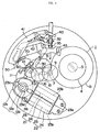
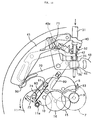
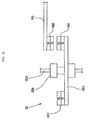
- Fig. 1 is a plan view showing principal part of an electronically controlled mechanical watch according to a first embodiment of the present invention
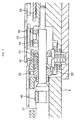
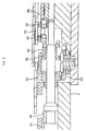
- Figs. 2 and 3 are sectional views of the principal part.
- the ratchet wheel 4 is meshed with a detent (not shown) so that it is allowed to rotate counterclockwise, but checked from rotating clockwise.
- a manner of rotating the ratchet wheel 4 clockwise to wind up the mainspring 1a is similar to that employed in an automatically or manually wind-up mechanism of a mechanical watch, and therefore the manner is not described here.
- the rotation of the barrel wheel gear 1b is transmitted to a power generator 20 (rotor 12) after being sped up through a wheel train comprising a 2nd (center) wheel 7, a 3rd wheel 8, a 4th (second) wheel 9, a 5th first intermediate wheel 15, a 5th second intermediate wheel 16, a 5th wheel 10, and a 6th wheel 11.
- a power generator 20 (rotor 12) after being sped up through a wheel train comprising a 2nd (center) wheel 7, a 3rd wheel 8, a 4th (second) wheel 9, a 5th first intermediate wheel 15, a 5th second intermediate wheel 16, a 5th wheel 10, and a 6th wheel 11.
- train wheels are supported by the main plate 2 and a train wheel bridge 3.
- the coil blocks 21, 22 are each constructed by winding a coil 24 around a yoke 23.
- Each yoke 23 has an integral structure comprising a stator portion 23c arranged adjacent to the rotor 12, a core portion 23b around which the coil 24 is wound, and a magnetically communicating portion 23a coupled to a counterpart of the other yoke.
- the yokes 23, i.e., the coils 24, are arranged parallel to each other.
- the rotor 12 is arranged adjacent to the stator portions 23c with a rotor axis lying on a boundary line between the coils 24, and the stator portion 23c are arranged in transversely symmetrical relation with respect to the boundary line.
- the coils 24 are formed in the same number of windings.
- the term "the same number” includes not only the case where the numbers of windings are exactly equal to each other, but also the case where there is some error in the number of windings between the coils at such a level negligible from the entire coil, for example, on the order of several hundreds turns.
- the magnetically communicating portions 23a of the yokes 23 are coupled to each other through contact between their opposing side surfaces. Also, lower surfaces of the magnetically communicating portions 23a are held in contact with an auxiliary yoke for magnetic communication, not shown, which is arranged in bridging relation with respect to both the magnetically communicating portions 23a. With such an arrangement, the magnetically communicating portions 23a form two magnetically communicating paths, i.e., a magnetically communicating path passing the side surfaces of the magnetically communicating portions 23a and a magnetically communicating path passing the lower surfaces of the magnetically communicating portions 23a and the auxiliary yoke for magnetic communication. Thus, the yokes 23 form a looped magnetic circuit.
- the coils 24 are wound in the same direction along the longitudinal direction of each of the yokes 23 from the magnetically communicating portion 23a to the stator portion 23c.
- Ends of the coils 24 are connected to coil lead boards, not shown, provided on the magnetically communicating portions 23a of the yokes 23.
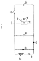
- An AC output from the power generator 20 is boosted and rectified through a boosting/rectifying circuit comprising a boosting capacitor 121 and diodes 122, 123. A resulting current is charged in a smoothing capacitor 130.
- a rotation controller 150 comprising an IC 151 and a quartz oscillator 152.
- the capacitor 130 is a layered ceramic capacitor having a relatively small capacity of about 0.5 ⁇ F.
- An electrolytic capacitor or the like may also be used as the capacitor 130, but a layered ceramic capacitor is more preferable because it has a longer life than an electrolytic capacitor and can provide a product life at a level of several tens years.
- the IC 151 and the quartz oscillator 152 are driven by the accumulated power to vary the amount of a current flowing through the coils of the power generator 20.
- the intensity of electromagnetic brake is adjusted to govern the cycle of rotation of the power generator 20, i.e., hands.
- the IC 151 of the rotation controller 150 includes a reference-signal output circuit for outputting a reference signal using an oscillation signal from the quartz oscillator 152, and a comparison-and-control signal output circuit for detecting a cycle of the rotor 12 of the power generator 20 as an electromagnetic converter, comparing the detected cycle with the reference signal, and outputting a comparison and control signal.
- the comparison and control signal the amount of a current flowing through the coils of the power generator 20 is varied to govern the cycle of rotation of the power generator 20.
- the manner of governing and controlling the power generator 20 may be carried out by using a chopping control scheme.
- a switch or the like which can connect output terminals of the power generator 20 into the closed loop state.
- the switch is intermittently turned on and off in accordance with the comparison and control signal, whereby short brake is applied to the power generator 20 for governing it.
- a capacitor 132 serving as an electricity accumulator is connected to the capacitor 130 via a switch 131.
- the capacitor 132 has a relatively large capacity of about 5 ⁇ F.
- the switch 131 when the switch 131 is turned on upon the crown being operated to the zero-th or first stage after setting the hands right, the capacitor 130 is momentarily charged with the power from the capacitor 132 and a predetermined voltage is applied to the IC 151. Accordingly, the IC 151 is started up after about 1 second from application of the voltage.
- Means for varying the amount of a current flowing through the coils can be effectively implemented, for example, by a method of changing resistance of a load control circuit connected in parallel to both the terminals of the power generator 20 as disclosed in Embodiment 1 of Japanese Unexamined Patent Application Publication No. 8-101284, or a method of changing the number of boosting steps as disclosed in Embodiment 2 thereof.
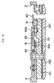
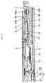
- the operation of setting minute and second hands right is performed by pulling out the crown, axially moving the winding stem 31 and setting it to the second stage, moving a sliding pinion 35 toward a setting wheel 36 to mesh them with each other under the action of a setting lever 40, a yoke holder 41 and a yoke 42, and moving the setting wheel 36 toward a minute wheel 38 by a setting wheel lever 43 to mesh them with each other, thereby rotating an hour pinion 6a and an hour wheel 6b, as shown in Fig. 2.
- the setting wheel lever 43 is not moved and only the yoke 42 is moved to mesh the sliding pinion 35 with the setting wheel 36. Therefore, the calendar can be corrected through a calendar corrector transmitting wheel 45.
- the electronically controlled mechanical watch further includes a starter operated by manipulating the crown, more concretely, a rotation driving means 50 serving as a startup member.
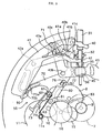
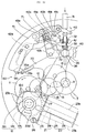
- the starter (rotation driving means) 50 is made up of a startup spring 60 for rotating the 6th wheel 11 midway the wheel train and driving the power generator 20, a reset lever 70 moved with movement of the setting lever 40 and being able to bias the startup spring 60, and a train wheel setting lever 80 moved with movement of the reset lever 70 and engaged with the 4th wheel 9, which rotates the second hand, for restricting rotation of the 4th wheel 9.
- the setting lever 40 is, as shown in Figs. 5 and 6, supported rotatably about a shaft 40a and engaged with the winding stein 31. Then, the setting lever 40 includes a positioning pin 40b engageable with any of three engagement grooves 41a, 41b, 41c formed in the yoke holder 41, and a pin 40c engaged in grooves 43a, 71 formed respectively in the setting wheel lever 43 and the reset lever 70, the pin 40c being also shown in Fig. 9. Further, a corner portion of the setting lever 40 is constructed to be able to contact the yoke 42 for turning the same.
- the yoke 42 is supported rotatably about a shaft 42a.
- the yoke 42 has one end engaged with the sliding pinion 35. Therefore, when the winding stem 31 is pulled out to the first or second stage and the setting lever 40 is rotated counterclockwise in the drawings, the one end of the yoke 42, i.e., the sliding pinion 35, is pushed by the setting lever 40 to move toward the center of the watch for engagement with the setting wheel 36.
- the setting wheel lever 43 Upon the pin 40c being moved in the groove 43a, the setting wheel lever 43 is turned about a shaft 43b.
- a shape of the groove 43a is designed such that the setting wheel lever 43 is allowed to move in two steps; one step in which the crown is set to the zero-th or first stage and the other step in which the crown is set to the second stage.
- the setting wheel 36 is attached to the setting wheel lever 43, as described above, and with the movement of the setting wheel lever 43, the setting wheel 36 is moved toward the center of the watch for engagement with the minute wheel 38.
- the reset lever 70 is supported rotatably about a shaft 72.
- a shape of the groove 71 is designed such that the reset lever 70 is likewise allowed to move in two steps; one step in which the crown is set to the zero-th or first stage and the other step in which the crown is set to the second stage.
- the reset lever 70 includes a latch portion 73 capable of engaging with a pinion 11a of the 6th wheel 11, which is a rotation target gear, and latching the pinion 11a into the non-rotatable state, a startup-spring biasing portion 74 for, when the latch portion 73 is engaged with the pinion 11a, biasing the startup spring 60 through a predetermined amount and bringing an engaging portion 63 at a fore end of the startup spring 60 into engagement with an engaged portion (tooth) of the rotation target gear 11a, and two switch portions 75a, 75b arranged in a hole 90 formed in a circuit board.
- the reset lever 70 constitutes a startup-spring operating member.
- the switch portion 75a of the reset lever 70 is brought into contact with the circuit board when the winding stem 31 is in the zero-th or first stage, and is moved away from the circuit board when the winding stem 31 is in the second stage.
- This mechanical switch portion 75a of the reset lever 70 constitutes the aforesaid switch 131 for the capacitor 132.
- the switch portion 75b of the reset lever 70 is brought into contact with the circuit board at one side of the hole 90 when the winding stem 31 is in the zero-th or first stage, and is brought into contact with the circuit board at the other side of the hole 90 when the winding stem 31 is in the second stage.
- the train wheel setting lever 80 is rotatable about a shaft 81 and has one end portion 82 engaged in an engagement hole 76 of the reset lever 70 so as to turn with turning of the reset lever 70.
- the other end portion 83 of the train wheel setting lever 80 is bent upward such that it is able to engage with the 4th wheel 9.
- the setting wheel 36 is held in a position out of engagement with the minute wheel 38. Further, the latch portion 73 and the startup-spring biasing portion 74 of the reset lever 70 are held in positions apart away from the pinion 11a and the startup spring 60, respectively, and the train wheel setting lever 80 is held in a position apart away from the 4th wheel 9.
- the setting lever 40 is rotated counterclockwise about the shaft 40a and the positioning pin 40b of the setting lever 40 is engaged in the engagement groove 41b of the yoke holder 41.
- the end portion of the yoke 42 is pushed by the corner portion of the setting lever 40 toward the center of the watch, causing the sliding pinion 35 to move toward the setting wheel 36.
- the setting wheel lever 43 is rotated clockwise about the shaft 43b by the pin 40c of the setting lever 40, causing the setting wheel 36 to move toward the minute wheel 38.
- the sliding pinion 35 is engaged with the setting wheel 36 and the setting wheel 36 is engaged with the minute wheel 38 so that the time setting can be made by turning the crown.
- the reset lever 70 is rotated counterclockwise about the shaft 72.
- the train wheel setting lever 80 is rotated clockwise and engaged with the 4th wheel 9.
- the 4th wheel 9, i.e., the second hand, is thereby restricted from rattling due to backlash in the rotating direction during the hand setting operation.
- the startup spring 60 is biased by the startup-spring biasing portion 74 of the reset lever 70 and is deflected to such an extent that the engaging portion 63 at the fore end of the startup spring 60 is engaged with one tooth, i.e., the engaged portion, of the 6th pinion 11a.
- the latch portion 73 of the reset lever 70 is engaged with another tooth of the 6th pinion 11a, the amount of biasing (deflection) of the startup spring 60 is always maintained constant.
- the train wheel setting lever 80 is rotated counterclockwise and the other end portion 83 of the lever 80 is disengaged from the 4th wheel 9, allowing the second hand to rotate.
- the latch portion 73 and the startup-spring biasing portion 74 are quickly disengaged from the 6th wheel pinion 11a and the startup spring 60, respectively, with the movement of the reset lever 70.
- the rotating force thus produced may be appropriately set in practice.
- the produced rotating force is set to a level enough to rotate the rotor 12 at the reference speed (speed at which the hands are allowed to move precisely, i.e., speed at which the second hand, for example, is moved in one second through a angular distance corresponding to one second; e.g., 8 Hz).
- the power generator 20 Upon the crown being pushed in for return from the hand setting operation, the power generator 20 starts to operate. At this startup of the power generator 20, the rotating force applied to the 6th pinion 11a by the startup spring 60 is transmitted to the rotor 12 in addition to the rotating force from the mainspring 1a. Accordingly, a large rotating force is temporarily applied to the rotor 12, whereby the rotor 12 is rotated at an increased speed as soon as the startup and the power outputted from the power generator 20 is increased up to a large value in a short time.
- This embodiment thus constructed has the following advantages.
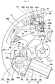
- Fig. 12 is a plan view showing principal part of an electronically controlled mechanical watch according to a second embodiment of the present invention
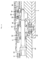
- Figs. 13 and 14 are sectional views of the principal part.
- the electronically controlled mechanical watch includes a movement barrel 1 comprising a mainspring 1a serving as a mechanical energy source, a barrel wheel gear 1b, a barrel arbor, and a barrel cover 1d.
- the mainspring 1a has an outer end fixed to the barrel wheel gear 1b and an inner end fixed to the barrel arbor.
- the barrel arbor is inserted through a barrel axle fixed to a main plate 2 and is fixed by a ratchet wheel screw 5 for rotation together with a ratchet wheel 4.
- the ratchet wheel 4 is meshed with a detent (not shown) so that it is allowed to rotate counterclockwise, but checked from rotating clockwise.
- a manner of rotating the ratchet wheel 4 clockwise to wind up the mainspring 1a is similar to that employed in an automatically or manually wind-up mechanism of a mechanical watch, and therefore the manner is not described here.
- the rotation of the barrel wheel gear 1b is transmitted to a power generator 20 (rotor 12) after being sped up through a wheel train comprising a 2nd (center) wheel 7, a 3rd wheel 8, a 4th (second) wheel 9, a 5th first intermediate wheel 15, a 5th second intermediate wheel 16, a 5th wheel 10, and a 6th wheel 11.
- a power generator 20 (rotor 12) after being sped up through a wheel train comprising a 2nd (center) wheel 7, a 3rd wheel 8, a 4th (second) wheel 9, a 5th first intermediate wheel 15, a 5th second intermediate wheel 16, a 5th wheel 10, and a 6th wheel 11.
- train wheels are supported by the main plate 2 and a train wheel bridge 3.
- the power generator 20 is made up of the rotor 12 and coil blocks 21, 22.
- the rotor 12 is made up of a rotor pinion 12a, a rotor magnet 12b, and a rotor inertia disk 12c.
- the rotor inertia disk 12c serves to reduce variations in rotational speed of the rotor 12, which are caused due to variations in driving torque from the movement barrel 1.
- a wave-shaped tooth profile 12d is formed all over an outer peripheral edge surface defined as an outer peripheral portion of the rotor inertia disk 12c.
- the rotor inertia disk 12c is attached to a rotor's rotating shaft through a slip mechanism.
- the slip mechanism is implemented by controlling a fitting force of the rotor inertia disk 12c to the rotor's rotating shaft, or providing a rubber or the like, not shown, in a fitting portion between the rotor inertia disk 12c and the rotor's rotating shaft.
- the coil blocks 21, 22 are each constructed by winding a coil 24 around a yoke 23.
- Each yoke 23 has an integral structure comprising a stator portion 23c arranged adjacent to the rotor 12, a core portion 23b around which the coil 24 is wound, and a magnetically communicating portion 23a coupled to a counterpart of the other yoke.
- the yokes 23, i.e., the coils 24, are arranged parallel to each other.
- the rotor 12 is arranged adjacent to the stator portions 23c with a rotor axis lying on a boundary line between the coils 24, and the stator portion 23c are arranged in transversely symmetrical relation with respect to the boundary line.
- a positioning member 25 is disposed in a stator hole 23d of each yoke 23 in which the rotor 12 is disposed.
- a positioning jig 26 in the form of an eccentric pin is disposed midway between each yoke 23 in the longitudinal direction, i.e., between the stator portion 23c and the magnetically communicating portion 23a of each yoke 23.
- the coils 24 are formed in the same number of windings.
- the term "the same number” includes not only the case where the numbers of windings are exactly equal to each other, but also the case where there is some error in the number of windings between the coils at such a level negligible from the entire coil, for example, on the order of several hundreds turns.
- the magnetically communicating portions 23a of the yokes 23 are coupled to each other through contact between their opposing side surfaces. Also, lower surfaces of the magnetically communicating portions 23a are held in contact with an auxiliary yoke for magnetic communication, not shown, which is arranged in bridging relation with respect to both the magnetically communicating portions 23a. With such an arrangement, the magnetically communicating portions 23a form two magnetically communicating paths, i.e., a magnetically communicating path passing the side surfaces of the magnetically communicating portions 23a and a magnetically communicating path passing the lower surfaces of the magnetically communicating portions 23a and the auxiliary yoke for magnetic communication. Thus, the yokes 23 form a looped magnetic circuit.
- the coils 24 are wound in the same direction along the longitudinal direction of each of the yokes 23 from the magnetically communicating portion 23a to the stator portion 23c.
- Ends of the coils 24 are connected to coil lead boards, not shown, provided on the magnetically communicating portions 23a of the yokes 23.
- An AC output from the power generator 20 is boosted and rectified through a boosting/rectifying circuit comprising a boosting capacitor 121 and diodes 122, 123. A resulting current is charged in a smoothing capacitor 130.
- a rotation controller 150 comprising an IC 151 and a quartz oscillator 152.
- the capacitor 130 is a layered ceramic capacitor having a relatively small capacity of about 0.5 ⁇ F.
- An electrolytic capacitor or the like may also be used as the capacitor 130, but a layered ceramic capacitor is more preferable because it has a longer life than an electrolytic capacitor and can provide a product life at a level of several tens years.
- the IC 151 of the rotation controller 150 includes a reference-signal output circuit for outputting a reference signal using an oscillation signal from the quartz oscillator 152, and a comparison-and-control signal output circuit for detecting a cycle of the rotor 12 of the power generator 20 as an electromagnetic converter, comparing the detected cycle with the reference signal, and outputting a comparison and control signal.
- the amount of a current flowing through the coils of the power generator 20 is varied to govern the cycle of rotation of the power generator 20.
- the manner of governing and controlling the power generator 20 may be carried out by using a chopping control scheme.
- a switch or the like which can connect output terminals of the power generator 20 into the closed loop state.
- the switch is intermittently turned on and off in accordance with the comparison and control signal, whereby short brake is applied to the power generator 20 for governing it.
- a capacitor 132 serving as an electricity accumulator is connected to the capacitor 130 via a switch 131.
- the capacitor 132 has a relatively large capacity of about 5 ⁇ F.
- the switch 131 is constructed, as described later, by a mechanical switch that is turned on when a not-shown crown (external operating member) is manipulated and a winding stem is set to the zero-th stage (normal hand driving mode) or the first stage (calendar correcting mode), and is turned off when the winding stem is set to the second stage (hand setting mode). Therefore, when the power generator 20 is in operation, the power from the power generator 20 is accumulated in not only the capacitor 130, but also the capacitor 132. When the power generator 20 is stopped during the hand setting operation, the switch 131 is turned off and hence the voltage of the capacitor 132 is maintained.
- the switch 131 when the switch 131 is turned on upon the crown being operated to the zero-th or first stage after setting the hands right, the capacitor 130 is momentarily charged with the power from the capacitor 132 and a predetermined voltage is applied to the IC 151. Accordingly, the IC 151 is started up after about 1 second from application of the voltage.
- Means for varying the amount of a current flowing through the coils can be effectively implemented, for example, by a method of changing resistance of a load control circuit connected in parallel to both the terminals of the power generator 20 as disclosed in Embodiment 1 of Japanese Unexamined Patent Application Publication No. 8-101284, or a method of changing the number of boosting steps as disclosed in Embodiment 2 thereof.
- the operation of setting minute and second hands right is performed by pulling out the crown, axially moving the winding stem 31 and setting it to the second stage, moving a sliding pinion 35 toward a setting wheel 36 to mesh them with each other under the action of a setting lever 40, a yoke holder 41 and a yoke 42, and moving the setting wheel 36 toward a minute wheel 38 by a setting wheel lever 43 to mesh them with each other, thereby rotating an hour pinion 6a and an hour wheel 6b, as shown in Fig. 13.
- the setting wheel lever 43 is not moved and only the yoke 42 is moved to mesh the sliding pinion 35 with the setting wheel 36. Therefore, the calendar can be corrected through a calendar corrector transmitting wheel 45.
- the electronically controlled mechanical watch further includes a starter operated by manipulating the crown.
- the starter 50 includes a reset lever 70 moved with movement of the setting lever 40 and serving as a startup member which directly applies a rotating force to the rotor 12 for rotating it.
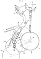
- the setting lever 40 is, as shown in Figs. 16 and 17, supported rotatably about a shaft 40a and engaged with the winding stem 31. Then, the setting lever 40 includes a positioning pin 40b engageable with any of three engagement grooves 41a, 41b, 41c formed in the yoke holder 41, and a pin 40c engaged in grooves 43a, 71 formed respectively in the setting wheel lever 43 and the reset lever 70, the pin 40c being also shown in Fig. 20. Further, a corner portion of the setting lever 40 is constructed to be able to contact the yoke 42 for turning the same.
- the yoke holder 41 is constructed such that the position of the winding stem 31, i.e., of the crown, can be set to any of three stages, i.e., zero-th, first and second stages, by engaging the positioning pin 40b of the setting lever 40 in corresponding one of the engagement grooves 41a - 41c.
- the reset lever 70 is supported rotatably about a shaft 72, as also shown in Fig. 21.
- a shape of the groove 71 is designed such that the reset lever 70 is likewise allowed to move in two steps; one step in which the crown is set to the zero-th or first stage and the other step in which the crown is set to the second stage.
- the reset lever 70 includes an engaging portion 77 capable of engaging with an engaged portion, i.e., the tooth profile 12d of the rotor inertia disk 12c, which constitutes the outer peripheral portion of the rotor 12, and two switch portions 75a, 75b arranged in a hole 90 formed in a circuit block 180.
- the reset lever 70 is arranged such that when the crown is pulled out to the second stage, the engaging portion 77 is engaged with the tooth profile 12d of the rotor inertia disc 12c, and when the crown is pushed in, the engaging portion 77 is moved for applying a rotating force to the rotor inertia disc 12c.
- the switch portion 75a of the reset lever 70 is brought into contact with the circuit block 180 on one side of the hole 90 when the winding stem 31 is in the zero-th or first stage, and is brought into contact with the circuit block 180 on the other side of the hole 90 when the winding stem 31 is in the second stage.
- Such an arrangement makes it possible to detect whether the winding stem 31 is in one of the zero-th and first stages or the second stage.
- the switch portion 75b of the reset lever 70 is brought into contact with the circuit block 180 when the winding stem 31 is in the zero-th or first stage, and is moved away from the circuit block 180 when the winding stem 31 is in the second stage.
- This mechanical switch portion 75b of the reset lever 70 constitutes the aforesaid switch 131 for the capacitor 132.
- the circuit block 180 is constructed by attaching art IC, for example, to a flexible board. As shown in Figs. 18, 20 and 21, the circuit block 180 is fixed by being held between a circuit receiving seat 181 screwed to the main plate 2 and a circuit retaining seat 182 also screwed to the main plate 2.
- the setting wheel 36 is held in a position out of engagement with the minute wheel 38. Further, the engaging portion 77 of the reset lever 70 is held in a position apart away from the rotor inertia disk 12c.
- the setting lever 40 is rotated counterclockwise about the shaft 40a and the positioning pin 40b of the setting lever 40 is engaged in the engagement groove 41b of the yoke holder 41.
- the end portion of the yoke 42 is pushed by the corner portion of the setting lever 40 toward the center of the watch, causing the sliding pinion 35 to move toward the setting wheel 36.
- the setting wheel lever 43 is rotated clockwise about the shaft 43b by the pin 40c of the setting lever 40, causing the setting wheel 36 to move toward the minute wheel 38.
- the sliding pinion 35 is engaged with the setting wheel 36 and the setting wheel 36 is engaged with the minute wheel 38 so that the time setting can be made by turning the crown.
- the reset lever 70 is rotated clockwise about the shaft 72. With the rotation of the reset lever 70, the engaging portion 77 of the reset lever 70 is engaged with the rotor inertia disk 12c.
- the setting lever 40 When the crown is pushed in to finish the hand setting operation after turning the crown and setting the hands right, the setting lever 40 is rotated clockwise and the pin 40c is moved within the groove 71 in interlock with the pushing-in of the crown, as shown in Fig. 22.
- the reset lever 70 is thereby rotated counterclockwise for return to the original position.
- the rotating force thus produced may be appropriately set in practice.
- the produced rotating force is set to a level enough to rotate the rotor 12 at a speed close to the reference one (speed at which the hands are allowed to move precisely, i.e., speed at which the second hand, for example, is moved in one second through a angular distance corresponding to one second; e.g., 8 Hz).
- the power generator 20 Upon the crown being pushed in for return from the hand setting operation, the power generator 20 starts to operate. At this startup of the power generator 20, the rotating force is applied to the rotor inertia disk 12c by the reset lever 70 in addition to the rotating force from the mainspring 1a. Accordingly, the rotor 12 is rotated at an increased speed as soon as the startup and the power outputted from the power generator 20 is increased up to a large value in a short time.
- This second embodiment thus constructed has the following advantages.
- the latch portion 73 and the startup-spring biasing portion 74 of the reset lever 70 are formed as integral parts of a one-piece member and the relative positional relationship between them is not changed.
- a slit is formed in the reset lever 70 between the latch portion 73 engaging with the 6th pinion 11a and the startup-spring biasing portion 74 for biasing the startup spring 60 so that the latch portion 73 and the startup-spring biasing portion 74 are constructed as separate pieces and the relative positional relationship between them is changeable.
- the startup spring 60 is fixed to the main plate 2 by the set pin 61 so that the initial position of the startup spring 60 can be adjusted by rotating the pin 61.
- the startup spring 60 is fixed by press-fitting its base end between two projections 2a formed on the main plate 2.
- the reset lever 70 is rotated clockwise in the drawing for return to the original position in response to the pushing-in of the crown.
- the startup-spring biasing portion 74 is first moved and the latch portion 73 is then moved in such a manner that the portions 74, 73 quickly depart away respectively from the startup spring 60 and the pinion 11a. Therefore, the startup spring 60 is returned to the original position by its own spring force.
- a mechanical rotating force is applied to the 6th pinion 11a, whereby the rotor 12 is rotated as with the above first embodiment.
- this embodiment can provide another advantage (13) that, even with some variations in dimensional accuracy of parts of the reset lever 70, e.g., the latch portion 73, resulting fluctuations in the mechanical rotating force applied to the pinion 11a are held down and stable rotation of the pinion 11a can be achieved.
- Still another advantage (14) is that the latch portion 73 can be always set so as to engage with the pinion 11a earlier such that the timing at which the latch portion 73 is engaged with the pinion 11a and the timing at which the engaging portion 63 of the startup spring 60 is engaged with the engaged portion of the pinion 11a always occur in the constant sequence; hence the startup spring 60 can be positively and easily engaged with the pinion 11a.
- the startup spring 60 is overly biased by the startup-spring biasing portion 74 when the latch portion 73 is engaged with the pinion 11a. Accordingly, the mechanical rotating force applied to the pinion 11a becomes too large.
- the initial position of the startup spring 60 must be adjusted by the set pin 61, thus resulting in a fear of lowering of the production efficiency.
- the latch portion 73 and the startup-spring biasing portion 74 are formed as separate pieces, some dimensional error can be absorbed, even if it occurs, through flexing of the latch portion 73, for example. As a result, adjustment of the initial position of the startup spring 60 is no longer needed.
- Fig. 26 shows, in enlarged scale, an area including a rotor 12 according to the fourth embodiment of the present invention. While the tooth profile 12d is formed, as the engaged portion, along the overall circumference of the rotor inertia disk 12c in the above second embodiment, the tooth profile 12d is partly formed along the circumference of the rotor inertia disk 12c in this fourth embodiment.
- the tooth profile 12d of the rotor inertia disk 12c is formed in two regions which are parts of the outer circumference of the rotor inertia disk 12c and are opposed to each other. Then, the rotor magnet 12b is set such that, when the reset lever 70 is engaged with the tool profile 12d, the magnetic-pole direction of the rotor magnet 12b is deviated from the diametrical direction in which the tooth profiles 12d are positioned. With such an arrangement, when the engaging portion 77 of the reset lever 70 is engaged with the tooth profile 12d, the rotor 12 can be restricted to a position offset from the statically stable position thereof.
- Figs. 27 and 28 show an area including a rotor 12 according to a fifth embodiment of the present invention.
- the rotor 12 in the above second embodiment is constructed as one having the similar structure to that of a brushless motor.
- the rotor 12 in this embodiment includes pairs of disk-shaped rotor magnets 12b arranged with a spacing left in the axial direction for each pair.
- the rotor magnet 12b of each pair is supported by a plate-shaped back yoke 12e.
- a board 223 serving as a part located opposite to the rotor magnets 12b is arranged to lie between the paired rotor magnets 12b, and includes a coil 123 disposed in a position corresponding to the paired rotor magnets 12b.
- the rotor 12 including the disk-shaped rotor magnets 12b serves itself as an inertia disk, and therefore the rotor inertia disk 12c used in the above second embodiment is not provided here.
- a tooth profile 12d similar to that in the above second embodiment is formed in one of the two back yokes 12e.
- a rotating force is directly applied to the back yoke 12e, i.e., the rotor 12.
- This fifth embodiment thus constructed can provide the same advantages as (21) to (31) of the above second embodiment.
- a power generator having a structure similar to that used in this embodiment is advantageous in leaking a less amount of magnetic flux and producing a less amount of iron loss, but has a large weight or inertia and is inferior in the startup characteristic.
- the startup characteristic of such a power generator can be improved by directly rotating the back yoke 12e using the reset lever 70.
- Fig. 29 schematically shows a rotor 12 according to a sixth embodiment of the present invention. While a rotating force is applied to the rotor 12 by bringing the reset lever 70 into direct contact with the rotor inertia disk 12c in the above second embodiment, a rotating force is applied to the rotor 12 by utilizing magnetic forces in this sixth embodiment.
- a magnet moving in response to the manipulation of the crown is disposed at a fore end of the reset lever 70, and the fore end of the reset lever 70 is extended up to a position close to the rotor magnet 12b.
- a rotating force is thus applied to the rotor 12 with magnetic forces acting between the magnet at the fore end of the reset lever 70 and the rotor magnet 12b, i.e., through magnetic engagement.
- the rotor magnet 12b When the fore end of the reset lever 70 is positioned close to the rotor magnet 12b, the rotor magnet 12b is rotated such that a magnetic pole (e.g., an N pole) of the rotor magnet 12b causing attraction forces with respect to a magnetic pole (e.g., a S pole) at the fore end of the reset lever 70 is positioned on the same side as the reset lever 70. Then, when the reset lever 70 is further rotated counterclockwise, the rotor magnet 12b is rotated clockwise with the attraction forces acting between them. A rotating force is thereby directly applied to the rotor 12.
- a magnetic pole e.g., an N pole
- a magnetic pole e.g., a S pole
- this sixth embodiment can provide another advantage (33) that, since a rotating force is directly applied to the rotor 12 by utilizing magnetic forces without bringing the reset lever 70 into direct contact with the rotor 12, it is possible to prevent wears of the reset lever 70 and the rotor 12.
- Still another advantage (34) is that, since the rotor magnet 12b serves also as a magnet to be disposed on the side of the rotor 12, there is no need of additionally providing a magnet on the side of the rotor 12; hence the cost can be reduced and an increase in weight can be suppressed.
- a plurality of magnets 161 are arranged on an upper surface (or a lower surface) of the rotor inertia disk 12c along its circumferential edge, and the rotor 12 is rotated using the magnets 161 and a magnet 162 disposed at the fore end of the reset lever 70 on the underside thereof.
- Magnetic poles of the magnet 161 on the side of the reset lever 70 and magnetic poles of the magnet 162 on the side of the, rotor inertia disk 12c are arranged such that mutually attracting magnetic poles (S and N poles) of both the magnets 161, 162 face each other.
- both the magnets 161, 162 are attracted to each other and a rotating force is applied to the rotor 12 due to attraction forces produced therebetween.
- this seventh embodiment can provide another advantage (35) that the reset lever 70 having a magnet is not required to be extended up to a position corresponding to the center of rotation of the rotor 12 unlike the case of using the rotor magnet 12b as a magnet on the rotor side; hence flexibility in arrangement of the reset lever 70 can be increased and the efficiency in use of a space can be improved.
- startup member comprising the startup spring 60 and the startup-spring operating member (reset lever 70), which is employed in the first and third embodiments, may be used as the starter engaging with the outer peripheral portion of the rotor 12 in the second embodiment.
- the starter 50 constituted by the reset lever 70 having the engaging portion 77 which is employed in the second embodiment, may be used to rotate the rotation target gear, e.g., the 6th pinion 11a, provided in the wheel train serving as a mechanical energy transmitting means.
- the starter of the present invention is able to engage with the rotation target gear, the pinion or the rotor 12, of the mechanical energy transmitting means, thereby applying a rotating force to the same.
- the startup member for rotating the rotor 12 in the starter for the electromagnetic converter of the present invention has been described as rotating the rotor 12 forward in the rotating direction.
- the startup member may be constructed to rotate the rotor 12 backward in the rotating direction.
- the rotor 12 is rotated backward by the startup member, but it is rotated forward in the rotating direction with mechanical energy produced by the spring, for example, immediately after the backward rotation.
- a frictional force imposed on the rotor 12 is reduced from a large value caused by statical friction down to a small value caused by kinetic friction, enabling the rotor to be more easily started up.
- the rotor rotational speed is quickly increased. Even with the fact that the rotor is initially rotated backward, the startup characteristic of the rotor can be improved as a total effect resulted from using the startup member.
- the engaging portion 63, 77 engaging with the rotation target gear e.g., the 6th pinion 11a or the rotor 12 (rotor inertia disk 12c)
- the moving direction of the engaging portion 63, 77 may be not exactly in the tangential direction, but substantially in the tangential direction.
- the engaging portion 63, 77 may also be moved in any direction deviated from the tangential direction within the range of a inclination defined by an angle (frictional angle) corresponding to the coefficient of friction in a contact area between the engaging portion 63, 77 and the rotor inertia disk 12c. If the moving direction of the engaging portion 63, 77 is within the range of the substantially tangential direction, a similar working effect to that in the case of moving the engaging portion 63, 77 exactly in the tangential direction can be obtained. It is however most preferable that the moving direction is set to the tangential direction as with the above embodiments.
- the contact areas of the reset lever 70 and the rotor inertia disk 12c may be processed to have roughness by etching, discharge machining, cutting, etc. so that a rotating force is applied using a frictional force, etc. produced by the processed contact areas.
- a frictional force may be instead utilized for engagement between them.
- the rotating force it is also preferable that the rotating force be applied in the tangential direction of the rotor 12 or the pinion 11a.
- the direction of applying the rotating force is not necessarily set to the tangential direction.
- the rotating force be applied in the tangential direction of the gear or the rotor.
- the direction of applying the rotating force is not necessarily set to the tangential direction.
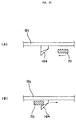
- the structure for engaging the reset lever 70 may be constructed as shown in Fig. 33. More specifically, an elastic member 164 is provided at a circumferential edge of the rotor inertia disk 12c such that the elastic member 164 has a distal end formed to space from the upper (or lower) surface of the rotor inertia disk 12c by a predetermined distance (Fig. 33(A)). For engaging the reset lever 70 with the rotor inertia disk 12c, the reset lever 70 is rotated such that the fore end of the reset lever 70 rides over the elastic member 164. Thus, as shown in Fig.
- the fore end of the reset lever 70 comes into abutment with the rear side of the elastic member 164 for engagement between the reset lever 70 and the rotor inertia disk 12c.
- the reset lever 70 is rotated in a direction opposite to the direction of engaging the same so as to pass a spacing between the elastic member 164 and the rotor inertia disk 12c.
- the rotation target gear in the first and third embodiments is not limited to the 6th pinion 11a, but may be other gear such as the 6th wheel 11 or the 5th wheel 10.
- the rotation target gear is preferably the 6th wheel 11 just one step before the rotor 12 as described in the above embodiments, and the rotating force is preferably applied to the 6th pinion 11a for more surely establishing the engagement between the startup spring 60 and the rotation target gear.
- the reset lever 70 in the first and third embodiments may be formed to have only the startup-spring biasing portion 74 with omission of the latch portion 73.
- the external operating member is not limited to the crown.
- the button may be used as the external operating member.
- the starter (rotation driving means) 50 it is just required that the starter (rotation driving means) 50 be operated in interlock with the operation of pushing the button.
- Using the crown as the external operating member is advantageous in that operability is improved because the starter can be operated in interlock with the operation for return from the hand setting.
- the switch 131 and the capacitor 132 are provided in the above embodiments, these components may be omitted with only the capacitor 130 provided.
- the capacitor 130 may have a small capacity as with the above embodiments so that the capacitor 130 is charged with the power only from the power generator 20 after the hand setting and the IC 151 is then started up.
- the capacitor 130 may have a large capacity so that the IC 151 is continuously driven by the capacitor 130 even during the hand setting.
- the present invention is not limited to such an arrangement.
- the tooth profile and the rotor magnet may be arranged in phase with each other.
- an advantage is obtained in that the effect of cogging torque at the startup is reduced and a required startup torque to be applied by the reset lever 70 can be reduced to a smaller value.
- the layout position of the magnets and the position of the reset lever 70 may be adjusted so that the rotor magnet 12b is offset from the statically stable position.
- the slip mechanism is not necessarily required between the rotor's rotating shaft and the rotor inertia disk 12c.
- the reset lever 70 While the reset lever 70 is engaged with the outer peripheral portion of the rotor inertia disk 12c in the second embodiment, it may be engaged with the rotor pinion 12a, for example.
- This modification is advantageous in that, because a gear usable as the engaged portion is already formed on the rotor pinion 12a, there is no need of additionally forming a tooth profile unlike the case of forming the tooth profile 12d of the rotor inertia disk 12c. Because of the rotor pinion 12a having a small radius, however, a greater force must be applied from the reset lever 70 and the rigidity of the reset lever 70 must be increased.
- Using the reset lever 70 in the same way as in the second embodiment provides an advantage that the rigidity required for the reset lever 70 can be reduced to a comparatively small value and the reset lever 70 can be formed of a comparatively thin member, thus resulting in the reduced weight and easier arrangement of the reset lever 70.
- Electromagnetic converters to which the present invention is applied are not limited to the power generator 20 in the above embodiments, but may include a motor as another example.
- the motor may be of the type having a similar structure to that used in the first to fourth embodiments, or the type having a similar structure to that used in the fifth embodiment.
- the starter for the electromagnetic converter according to the present invention is not limited to timepieces in application, but is also applicable to equipment and power generating units which incorporate various types of dynamos and motors, such as a portable hemomanometer, cellular phone, pager, pedometer, electronic calculator, portable personal computer, electronic notepad, portable radio, music box, metronome, and electric shavers.
- dynamos and motors such as a portable hemomanometer, cellular phone, pager, pedometer, electronic calculator, portable personal computer, electronic notepad, portable radio, music box, metronome, and electric shavers.
- the present invention can be applied to various equipment including electromagnetic converter such as power generators and motors.
- the mechanical energy source is not limited to a coiled spring, but may be a rubber, another type of spring, weight, etc. In other words, the mechanical energy source can be appropriately selected depending on the target to which the present invention is applied.
- the mechanical energy transmitting device for transmitting mechanical energy from the mechanical energy source, e.g., the mainspring, to the rotor of the power generator is not limited to the wheel train (gears) in the above embodiments, but may be implemented by using a friction pulley, belt and pulley, chain and sprocket wheel, rack and pinion, cam, etc.
- the mechanical energy transmitting device can be appropriately selected depending on the types of equipment to which the present invention is applied.
- a startup member which has an engaging portion mechanically engaging with an engaged portion of a rotation target gear, a pinion or a rotor of mechanical energy transmitting means.
- a mechanical rotating force can be more efficiently applied to the rotation target gear, the pinion or the rotor with higher stability.
- the efficiency in rotating the gear, the pinion or the rotor by the startup spring is increased, whereby the rotation target gear, the pinion or the rotor can be rotated with improved stability.
Landscapes
- Physics & Mathematics (AREA)
- General Physics & Mathematics (AREA)
- Engineering & Computer Science (AREA)
- Power Engineering (AREA)
- Connection Of Motors, Electrical Generators, Mechanical Devices, And The Like (AREA)
- Electromechanical Clocks (AREA)
Abstract
Description
Claims (25)
- A starter for an electromagnetic converter comprising at least a rotor and mechanical energy transmitting means, which is constituted by a wheel train made up of a plurality of gears and transmits mechanical energy to and from said rotor, thereby converting one of mechanical energy and electrical energy into the other,
wherein said starter includes a startup member which has an engaging portion capable of mechanically engaging with an engaged portion of a rotation target gear provided in said mechanical energy transmitting means, and which moves said engaging portion in response to operation of an external operating member for applying a rotating force to said rotation target gear, while said engaging portion is in engagement with said engaged portion, whereby said rotor is rotated. - A starter for an electromagnetic converter comprising at least a rotor and mechanical energy transmitting means, which is constituted by a wheel train made up of a plurality of gears and transmits mechanical energy to and from said rotor, thereby converting one of mechanical energy and electrical energy into the other,
wherein said starter includes a startup member which has an engaging portion capable of engaging with a rotation target gear provided in said mechanical energy transmitting means, and which moves said engaging portion substantially in the tangential direction of said rotation target gear in response to operation of an external operating member for applying a rotating force to said rotation target gear, whereby said rotor is rotated. - A starter for an electromagnetic converter comprising at least a rotor and mechanical energy transmitting means, which is constituted by a wheel train made up of a plurality of gears and transmits mechanical energy to and from said rotor, thereby converting one of mechanical energy and electrical energy into the other,
wherein said starter includes a startup member for, in response to operation of an external operating member, applying a rotating force to a pinion of a gear in said mechanical energy transmitting means, said gear being located just one step before said rotor, whereby said rotor is rotated. - A starter for an electromagnetic converter comprising at least a rotor and converting one of mechanical energy and electrical energy into the other,
wherein said starter includes a startup member for, in response to operation of an external operating member, applying a rotating force to said rotor of said electromagnetic converter, whereby said rotor is rotated. - A starter for an electromagnetic converter according to any one of Claims 2 to 4, wherein said rotation target gear, said pinion or said rotor includes an engaged portion, and said startup member includes an engaging portion capable of mechanically engaging with the engaged portion of said rotation target gear, said pinion or said rotor.
- A starter for an electromagnetic converter according to any one of Claims 2 to 4, wherein said startup member is magnetically engageable with said rotation target gear, said pinion or said rotor.
- A starter for an electromagnetic converter according to Claim 1 or 5, wherein said startup member engages the engaging portion of said startup member with the engaged portion of said rotation target gear, said pinion or said rotor in response to first operation of said external operating member, and moves the engaging portion of said startup member for applying a rotating force to said rotation target gear, said pinion or said rotor in response to second operation of said external operating member.
- A starter for an electromagnetic converter according to Claim 7, wherein the engaging portion of said startup member is moved substantially in the tangential direction of said rotation target gear, said pinion or said rotor in response to the second operation of said external operating member.
- A starter for an electromagnetic converter according to claim 7 or 8, wherein said startup member comprises a startup spring having an engaging portion capable of engaging with the engaged portion of said rotation target gear, said pinion or said rotor, and a startup-spring operating member for biasing said startup spring to engage the engaging portion of said startup spring with the engaged portion of said rotation target gear, said pinion or said rotor in response to the first operation of said external operating member, and releasing said startup spring from a biased state for returning said startup spring to an original position in response to the second operation of said external operating member, thereby applying a rotating force to said rotation target gear, said pinion or said rotor.
- A starter for an electromagnetic converter according to Claim 9, wherein said startup spring is a leaf spring, and the engaging portion of said startup spring, which engages with the engaged portion of said rotation target gear, said pinion or said rotor, is moved by said startup-spring operating member substantially in the tangential direction of said gear, said pinion or said rotor.
- A starter for an electromagnetic converter according to Claim 9 or 10, wherein an opposite end portion of said startup spring is fixed to a pin, and said pin is rotatably attached to a base of said electromagnetic converter.
- A starter for an electromagnetic converter according to any one of Claims 9 to 11, wherein said startup-spring operating member comprises a latch portion capable of engaging with said rotation target gear, said, pinion or said rotor to stop rotation thereof, and a startup-spring biasing portion for biasing said startup spring by a predetermined amount, while said latch portion is in engagement with said rotation target gear, said pinion or said rotor, thereby bringing the engaging portion of said startup spring into engagement with the engaged portion of said rotation target gear, said pinion or said rotor.
- A starter for an electromagnetic converter according to any one of Claims 9 to 12, wherein said external operating member is a crown, and
wherein said startup-spring operating member is constituted by a lever for biasing said startup spring to be engaged with the engaged portion of said rotation target gear, said pinion or said rotor when said crown is pulled out, and releasing said startup spring from the biased state for returning said startup spring to the original position when said crown is pushed in, thereby applying a mechanical rotating force to said rotation target gear, said pinion or said rotor. - A starter for an electromagnetic converter according to any one of Claims 1 to 13, wherein said electromagnetic converter includes a yoke and a coil.
- A starter for an electromagnetic converter according to Claim 14, wherein said electromagnetic converter is an electromagnetic converter including a core portion around which said coil is wound.
- A starter for an electromagnetic converter according to Claim 5, wherein the engaged portion of said rotor is formed along an outer peripheral portion of said rotor of said electromagnetic converter.
- A starter for an electromagnetic converter according to Claim 16, wherein said rotor of said electromagnetic converter includes an inertia plate, and the engaged portion of said rotor is formed along an outer peripheral portion of said inertia plate.
- A starter for an electromagnetic converter according to Claim 17, wherein said inertia plate is attached to a rotating shaft of said rotor through a slip mechanism.
- A starter for an electromagnetic converter according to any one of Claims 5 and 16 to 18, wherein said startup member enables said rotor to be restricted to a position offset from a statically stable position thereof when said startup member is engaged with the engaged portion of said rotor.
- A starter for an electromagnetic converter according to any one of Claims 1 to 19, wherein said startup member for rotating said rotor rotates said rotor forward in a rotating direction thereof.
- A timepiece comprising a mechanical energy source, an electromagnetic converter driven by said mechanical energy source and outputting electrical energy, a rotation controller operated with the electrical energy generated by said electromagnetic converter, hands driven under control by said rotation controller, and a starter for said electromagnetic converter according to any one of Claims 1 to 20.
- A timepiece comprising a mechanical energy source, a transmission wheel train for transmitting mechanical energy from said mechanical energy source, hands driven by said transmission wheel train and indicating the time of day, an electromagnetic converter including a rotor rotated through said transmission wheel train and outputting electrical energy, an electricity accumulator for accumulating an electromotive force generated by said electromagnetic converter, and a rotation controller operated by said electricity accumulator,
said rotation controller including a reference-signal output circuit for outputting a reference signal, and a comparison-and-control signal output circuit for detecting a cycle of said rotor of said electromagnetic converter, comparing the detected cycle with the reference signal, and outputting a comparison and control signal,
wherein said timepiece further comprises a starter for said electromagnetic converter according to any one of Claims 1 to 20, said starter providing a rotating force to act on said transmission wheel train or said rotor in response to operation of an external operating member. - A timepiece according to Claim 21 or 22, further comprising an electricity accumulator being able to accumulate the electrical energy outputted from said electromagnetic converter and connected to said rotation controller through a mechanical switch,
said mechanical switch being turned off in response to first operation of said external operating member to disconnect said electricity accumulator from said rotation controller, and being turned on in response to second operation of said external operating member to supply the electrical energy from said electricity accumulator to said rotation controller. - A timepiece according to any one of Claims 21 to 23, wherein the rotating force applied to said rotation target gear, said pinion or said rotor by said startup member is set to such a magnitude as causing said rotor of said electromagnetic converter to be started up at a reference speed.
- A timepiece comprising an electrical energy source, an electromagnetic converter driven by said electrical energy source and outputting mechanical energy, a rotation controller operated with electrical energy from said electrical energy source, hands driven under control by said rotation controller, and a starter for said electromagnetic converter according to any one of Claims 1 to 20.
Applications Claiming Priority (5)
| Application Number | Priority Date | Filing Date | Title |
|---|---|---|---|
| JP6046499 | 1999-03-08 | ||
| JP6046499 | 1999-03-08 | ||
| JP18903899 | 1999-07-02 | ||
| JP18903899 | 1999-07-02 | ||
| PCT/JP2000/001411 WO2000054113A1 (en) | 1999-03-08 | 2000-03-08 | Starting device for electromagnetic converter, and timepiece device |
Publications (3)
| Publication Number | Publication Date |
|---|---|
| EP1077395A1 true EP1077395A1 (en) | 2001-02-21 |
| EP1077395A4 EP1077395A4 (en) | 2004-11-17 |
| EP1077395B1 EP1077395B1 (en) | 2009-06-24 |
Family
ID=26401535
Family Applications (1)
| Application Number | Title | Priority Date | Filing Date |
|---|---|---|---|
| EP00907953A Expired - Lifetime EP1077395B1 (en) | 1999-03-08 | 2000-03-08 | Starting device for electromagnetic converter, and timepiece device |
Country Status (6)
| Country | Link |
|---|---|
| US (1) | US7031230B1 (en) |
| EP (1) | EP1077395B1 (en) |
| JP (1) | JP3575427B2 (en) |
| CN (1) | CN1208699C (en) |
| DE (1) | DE60042436D1 (en) |
| WO (1) | WO2000054113A1 (en) |
Families Citing this family (13)
| Publication number | Priority date | Publication date | Assignee | Title |
|---|---|---|---|---|
| ATE471538T1 (en) * | 2005-10-10 | 2010-07-15 | Montres Breguet Sa | CLOCK MOVEMENT WITH CONSTANT FORCE DEVICE |
| US7813227B2 (en) * | 2007-10-23 | 2010-10-12 | Montres Breguet S.A. | Musical module for a watch movement |
| EP2367260A1 (en) * | 2010-03-17 | 2011-09-21 | SCI Innovations Limited | Portable communication device |
| US9412002B2 (en) * | 2013-12-26 | 2016-08-09 | Intel Corporation | Wearable electronic device having a fingerprint identification display |
| KR20180059086A (en) * | 2016-11-25 | 2018-06-04 | 경희대학교 산학협력단 | Generator and mobile device having the same |
| EP3373081B1 (en) * | 2017-03-06 | 2021-05-26 | Montres Breguet S.A. | Clock movement provided with a device for positioning a mobile member in a plurality of discrete positions |
| EP3373080B1 (en) * | 2017-03-06 | 2021-05-05 | Montres Breguet S.A. | Clock movement provided with a device for positioning a mobile member in a plurality of discrete positions |
| JP7004895B2 (en) | 2017-06-15 | 2022-01-21 | ミツミ電機株式会社 | Locking device |
| EP3438763B1 (en) * | 2017-08-04 | 2020-05-06 | The Swatch Group Research and Development Ltd | Clock movement provided with an electromagnetic transducer |
| CN112576464B (en) * | 2020-12-14 | 2022-09-16 | 西北农林科技大学 | Friction nanometer power generation device of self-driven watch |
| WO2022176453A1 (en) * | 2021-02-17 | 2022-08-25 | シチズン時計株式会社 | Mechanical timepiece |
| EP4303667B1 (en) * | 2022-07-06 | 2025-08-27 | The Swatch Group Research and Development Ltd | Device for generating electrical energy for a timepiece |
| US12549067B2 (en) | 2022-08-23 | 2026-02-10 | Toto Ltd. | Power generation module and remote control device |
Family Cites Families (31)
| Publication number | Priority date | Publication date | Assignee | Title |
|---|---|---|---|---|
| US1986498A (en) | 1931-06-26 | 1935-01-01 | Chicago Flexible Shaft Co | Electric clock setting and starting mechanism |
| GB384441A (en) | 1931-12-09 | 1932-12-08 | Smith & Sons Ltd S | Improvements relating to electric clocks |
| US3579974A (en) * | 1967-04-08 | 1971-05-25 | Gehap Gmbh & Co Kg | Electronically-controlled drive mechanism particularly for clocks |
| JPS4836878B1 (en) | 1970-12-18 | 1973-11-07 | ||
| JPS4836878U (en) * | 1971-07-19 | 1973-05-04 | ||
| JPS4836878A (en) | 1971-09-14 | 1973-05-31 | ||
| JPS587358Y2 (en) * | 1973-06-29 | 1983-02-08 | 松下電工株式会社 | Tokei |
| JPS51133064A (en) | 1975-05-14 | 1976-11-18 | Seikosha Co Ltd | Starting apparatus of rotary car |
| JPS5644222Y2 (en) * | 1975-08-06 | 1981-10-16 | ||
| JPS5225776U (en) * | 1975-08-13 | 1977-02-23 | ||
| JPS5225776A (en) | 1975-08-20 | 1977-02-25 | Kuraray Co Ltd | Preparation of 2,4-disubstituted 6-membered cyclic ethers |
| JPS5287068A (en) | 1976-01-14 | 1977-07-20 | Matsushita Electric Works Ltd | Watch |
| JPS6054632B2 (en) | 1976-02-28 | 1985-11-30 | 松下電工株式会社 | clock |
| JPS6031185B2 (en) | 1976-09-29 | 1985-07-20 | セイコーインスツルメンツ株式会社 | portable power generator |
| JPS6055035B2 (en) | 1976-11-15 | 1985-12-03 | 松下電工株式会社 | watch starting device |
| JPS5644222A (en) | 1979-09-20 | 1981-04-23 | Matsushita Electric Ind Co Ltd | Analogue-digital converter |
| JPS56171112U (en) | 1980-05-15 | 1981-12-17 | ||
| JPS587358A (en) | 1981-07-07 | 1983-01-17 | Ricoh Co Ltd | Double valve mechanism |
| JPS5876171A (en) | 1981-10-31 | 1983-05-09 | 株式会社東芝 | Apparatus for treating papers |
| JPH0538262Y2 (en) * | 1987-11-06 | 1993-09-28 | ||
| KR950001429Y1 (en) * | 1988-01-25 | 1995-03-06 | 세이꼬 엡슨 가부시끼가이샤 | Electronic wrist watch equipped with power generator |
| JP2987449B2 (en) | 1990-02-23 | 1999-12-06 | オリンパス光学工業株式会社 | Electronic camera |
| JPH0538262A (en) | 1990-09-03 | 1993-02-19 | Kissei Pharmaceut Co Ltd | Thickening agent for liquid food |
| NL9001976A (en) * | 1990-09-07 | 1992-04-01 | Kinetron Bv | GENERATOR. |
| JP3115479B2 (en) | 1994-06-15 | 2000-12-04 | セイコーエプソン株式会社 | Electronically controlled watch with mainspring generator |
| JPH1066326A (en) | 1996-08-13 | 1998-03-06 | Yazaki Corp | Rotor of 2-pole label type stepping motor |
| JP3601258B2 (en) | 1997-06-19 | 2004-12-15 | セイコーエプソン株式会社 | Electronically controlled mechanical clock |
| JP3582304B2 (en) | 1997-06-19 | 2004-10-27 | セイコーエプソン株式会社 | Electronically controlled mechanical clock |
| JP3731296B2 (en) | 1997-07-09 | 2006-01-05 | セイコーエプソン株式会社 | Electronically controlled mechanical clock |
| CN100399217C (en) * | 1999-03-03 | 2008-07-02 | 精工爱普生株式会社 | Electronic device and control method thereof |
| DE69940344D1 (en) * | 1999-09-17 | 2009-03-12 | Eta Sa Mft Horlogere Suisse | Shockproof device for a generator powered by a flywheel |
-
2000
- 2000-03-08 JP JP2000604277A patent/JP3575427B2/en not_active Expired - Fee Related
- 2000-03-08 CN CN00800282.7A patent/CN1208699C/en not_active Expired - Fee Related
- 2000-03-08 WO PCT/JP2000/001411 patent/WO2000054113A1/en not_active Ceased
- 2000-03-08 DE DE60042436T patent/DE60042436D1/en not_active Expired - Lifetime
- 2000-03-08 EP EP00907953A patent/EP1077395B1/en not_active Expired - Lifetime
- 2000-03-08 US US09/674,868 patent/US7031230B1/en not_active Expired - Lifetime
Also Published As
| Publication number | Publication date |
|---|---|
| DE60042436D1 (en) | 2009-08-06 |
| JP3575427B2 (en) | 2004-10-13 |
| EP1077395A4 (en) | 2004-11-17 |
| US7031230B1 (en) | 2006-04-18 |
| CN1208699C (en) | 2005-06-29 |
| EP1077395B1 (en) | 2009-06-24 |
| CN1296579A (en) | 2001-05-23 |
| WO2000054113A1 (en) | 2000-09-14 |
Similar Documents
| Publication | Publication Date | Title |
|---|---|---|
| EP1077395B1 (en) | Starting device for electromagnetic converter, and timepiece device | |
| US7306364B2 (en) | Timepiece having a mechanical movement associated with an electronic regulator | |
| US7891862B2 (en) | Electromechanical escapement device and timepiece part utilizing such a device | |
| CN107870548B (en) | Automatic winding watch | |
| US6570824B1 (en) | Generator for a timepiece | |
| JPWO2000054113A1 (en) | Electromagnetic converter starter and timing device | |
| JPWO2001016655A1 (en) | Clock device | |
| EP4414793A1 (en) | Mechanical watch having mechanical movement and an electronic speed governing apparatus | |
| WO2001016655A1 (en) | Timepiece device | |
| JP2002228774A (en) | Piezoelectric governor and electronic equipment using this piezoelectric governor | |
| HK1035580A (en) | Starting device for electromagnetic converter, and timepiece device | |
| KR100321491B1 (en) | A coupling device between a source of mechanical energy and an electrical energy generator in a timepiece | |
| JPH058397B2 (en) | ||
| JP2002345208A (en) | Generator starter and timing device | |
| US20230009341A1 (en) | Timepiece provided with a mechanical movement and a device for correcting a displayed time | |
| US20050041535A1 (en) | Stopwatch and watch | |
| CN110161829B (en) | Timepiece oscillator insensitive to angular accelerations induced by wearing | |
| JPWO2000029911A1 (en) | Electronically controlled mechanical clock | |
| JP2002148363A (en) | clock | |
| JP7700553B2 (en) | Watch and watch manufacturing method | |
| JP3577909B2 (en) | Electronically controlled mechanical clock | |
| JP3632599B2 (en) | clock | |
| HK40078474B (en) | Timepiece component provided with a mechanical movement and a device for correcting a displayed time | |
| JPH0694850A (en) | Electronic clock with generator device | |
| CN115685721A (en) | Electronically controlled mechanical clocks |
Legal Events
| Date | Code | Title | Description |
|---|---|---|---|
| PUAI | Public reference made under article 153(3) epc to a published international application that has entered the european phase |
Free format text: ORIGINAL CODE: 0009012 |
|
| AK | Designated contracting states |
Kind code of ref document: A1 Designated state(s): AT BE CH CY DE DK ES FI FR GB GR IE IT LI LU MC NL PT SE |
|
| 17P | Request for examination filed |
Effective date: 20010227 |
|
| RBV | Designated contracting states (corrected) |
Designated state(s): CH DE FR GB LI |
|
| A4 | Supplementary search report drawn up and despatched |
Effective date: 20041005 |
|
| 17Q | First examination report despatched |
Effective date: 20071218 |
|
| GRAP | Despatch of communication of intention to grant a patent |
Free format text: ORIGINAL CODE: EPIDOSNIGR1 |
|
| GRAS | Grant fee paid |
Free format text: ORIGINAL CODE: EPIDOSNIGR3 |
|
| GRAA | (expected) grant |
Free format text: ORIGINAL CODE: 0009210 |
|
| AK | Designated contracting states |
Kind code of ref document: B1 Designated state(s): CH DE FR GB LI |
|
| REG | Reference to a national code |
Ref country code: GB Ref legal event code: FG4D |
|
| REG | Reference to a national code |
Ref country code: CH Ref legal event code: EP |
|
| REG | Reference to a national code |
Ref country code: CH Ref legal event code: NV Representative=s name: PATENTANWAELTE SCHAAD, BALASS, MENZL & PARTNER AG |
|
| REF | Corresponds to: |
Ref document number: 60042436 Country of ref document: DE Date of ref document: 20090806 Kind code of ref document: P |
|
| PLBE | No opposition filed within time limit |
Free format text: ORIGINAL CODE: 0009261 |
|
| STAA | Information on the status of an ep patent application or granted ep patent |
Free format text: STATUS: NO OPPOSITION FILED WITHIN TIME LIMIT |
|
| 26N | No opposition filed |
Effective date: 20100325 |
|
| REG | Reference to a national code |
Ref country code: HK Ref legal event code: WD Ref document number: 1035580 Country of ref document: HK |
|
| REG | Reference to a national code |
Ref country code: FR Ref legal event code: PLFP Year of fee payment: 17 |
|
| REG | Reference to a national code |
Ref country code: FR Ref legal event code: PLFP Year of fee payment: 18 |
|
| PGFP | Annual fee paid to national office [announced via postgrant information from national office to epo] |
Ref country code: CH Payment date: 20170314 Year of fee payment: 18 |
|
| PGFP | Annual fee paid to national office [announced via postgrant information from national office to epo] |
Ref country code: GB Payment date: 20170308 Year of fee payment: 18 |
|
| REG | Reference to a national code |
Ref country code: FR Ref legal event code: PLFP Year of fee payment: 19 |
|
| PGFP | Annual fee paid to national office [announced via postgrant information from national office to epo] |
Ref country code: DE Payment date: 20180220 Year of fee payment: 19 |
|
| PGFP | Annual fee paid to national office [announced via postgrant information from national office to epo] |
Ref country code: FR Payment date: 20180223 Year of fee payment: 19 |
|
| REG | Reference to a national code |
Ref country code: CH Ref legal event code: PL |
|
| GBPC | Gb: european patent ceased through non-payment of renewal fee |
Effective date: 20180308 |
|
| PG25 | Lapsed in a contracting state [announced via postgrant information from national office to epo] |
Ref country code: LI Free format text: LAPSE BECAUSE OF NON-PAYMENT OF DUE FEES Effective date: 20180331 Ref country code: GB Free format text: LAPSE BECAUSE OF NON-PAYMENT OF DUE FEES Effective date: 20180308 Ref country code: CH Free format text: LAPSE BECAUSE OF NON-PAYMENT OF DUE FEES Effective date: 20180331 |
|
| REG | Reference to a national code |
Ref country code: DE Ref legal event code: R119 Ref document number: 60042436 Country of ref document: DE |
|
| PG25 | Lapsed in a contracting state [announced via postgrant information from national office to epo] |
Ref country code: DE Free format text: LAPSE BECAUSE OF NON-PAYMENT OF DUE FEES Effective date: 20191001 |
|
| PG25 | Lapsed in a contracting state [announced via postgrant information from national office to epo] |
Ref country code: FR Free format text: LAPSE BECAUSE OF NON-PAYMENT OF DUE FEES Effective date: 20190331 |