EP1077382B1 - Reduced noise RF coil apparatus for MR imaging system - Google Patents
Reduced noise RF coil apparatus for MR imaging system Download PDFInfo
- Publication number
- EP1077382B1 EP1077382B1 EP00306988A EP00306988A EP1077382B1 EP 1077382 B1 EP1077382 B1 EP 1077382B1 EP 00306988 A EP00306988 A EP 00306988A EP 00306988 A EP00306988 A EP 00306988A EP 1077382 B1 EP1077382 B1 EP 1077382B1
- Authority
- EP
- European Patent Office
- Prior art keywords
- coil
- coil assembly
- tubular member
- gradient
- bore
- Prior art date
- Legal status (The legal status is an assumption and is not a legal conclusion. Google has not performed a legal analysis and makes no representation as to the accuracy of the status listed.)
- Expired - Lifetime
Links
Images

Classifications
-
- G—PHYSICS
- G01—MEASURING; TESTING
- G01R—MEASURING ELECTRIC VARIABLES; MEASURING MAGNETIC VARIABLES
- G01R33/00—Arrangements or instruments for measuring magnetic variables
- G01R33/20—Arrangements or instruments for measuring magnetic variables involving magnetic resonance
- G01R33/28—Details of apparatus provided for in groups G01R33/44 - G01R33/64
- G01R33/32—Excitation or detection systems, e.g. using radio frequency signals
- G01R33/34—Constructional details, e.g. resonators, specially adapted to MR
- G01R33/34007—Manufacture of RF coils, e.g. using printed circuit board technology; additional hardware for providing mechanical support to the RF coil assembly or to part thereof, e.g. a support for moving the coil assembly relative to the remainder of the MR system
-
- G—PHYSICS
- G01—MEASURING; TESTING
- G01R—MEASURING ELECTRIC VARIABLES; MEASURING MAGNETIC VARIABLES
- G01R33/00—Arrangements or instruments for measuring magnetic variables
- G01R33/20—Arrangements or instruments for measuring magnetic variables involving magnetic resonance
- G01R33/28—Details of apparatus provided for in groups G01R33/44 - G01R33/64
- G01R33/38—Systems for generation, homogenisation or stabilisation of the main or gradient magnetic field
- G01R33/385—Systems for generation, homogenisation or stabilisation of the main or gradient magnetic field using gradient magnetic field coils
- G01R33/3854—Systems for generation, homogenisation or stabilisation of the main or gradient magnetic field using gradient magnetic field coils means for active and/or passive vibration damping or acoustical noise suppression in gradient magnet coil systems
-
- G—PHYSICS
- G01—MEASURING; TESTING
- G01R—MEASURING ELECTRIC VARIABLES; MEASURING MAGNETIC VARIABLES
- G01R33/00—Arrangements or instruments for measuring magnetic variables
- G01R33/20—Arrangements or instruments for measuring magnetic variables involving magnetic resonance
- G01R33/28—Details of apparatus provided for in groups G01R33/44 - G01R33/64
- G01R33/32—Excitation or detection systems, e.g. using radio frequency signals
- G01R33/34—Constructional details, e.g. resonators, specially adapted to MR
- G01R33/34046—Volume type coils, e.g. bird-cage coils; Quadrature bird-cage coils; Circularly polarised coils
Definitions
- the invention disclosed and claimed herein generally pertains to an RF coil arrangement for a magnetic resonance (MR) imaging system or scanner. More particularly, the invention pertains to an arrangement wherein the RF coil of the MR scanner is selectively mounted in relation to other components of the scanner, to substantially reduce the noise or acoustic disturbance which is experienced by a patient located within the bore of the scanner, that is, within the MR imaging volume.
- MR magnetic resonance
- an MR imaging system or scanner commonly includes a cryostat, which contains a powerful superconductive main magnet positioned around a main magnet bore.
- the superconductive magnet is maintained at an extremely cold temperature and produces a strong static magnetic field, or B 0 field, within the bore, the B 0 field being directed along the bore axis.
- Other essential components of the MR system include the RF coil, or RF antenna, and the gradient coil assembly, which comprises a hollow cylindrical structure.
- the RF coil may be operated in a transmit mode, to generate MR signals in an imaging subject, or may be operated in a receive mode to detect the MR signals.
- the gradient coil assembly comprises one or more cylindrical coil forms, as well as a set of gradient coils supported thereby, to produce the X-, Y-, and Z-gradient magnetic fields. These fields are required to spatially encode MR data.
- the gradient coil assembly is positioned within the main magnet bore.
- the inner form comprises a tubular member which is inserted through the gradient coil assembly, in coaxial relationship therewith.
- the interior region of the inner tubular member generally comprises the patient bore or imaging volume of the associated MR system, that is, the volume which is disposed to receive a patient, and in which MR signals are generated and detected.
- the ends of the inner tubular member are attached to the cryostat, by means of end caps or the like, so that the tubular member is supported thereby.
- the RF coil is placed around the outside diameter of the inner tubular member, in close adjacent relationship, and supported or carried thereby.
- the tubular member is made of a non-electrically conductive material, so that it does not impede RF performance within the imaging volume.
- the inventors have recognized that such mechanical motion may be a principal reason for the occurrence of noise within the imaging volume. More specifically, the inventors have recognized that if the RF coil is joined to and supported upon the inner tubular member, the eddy current induced motion of the RF coil may drive the tubular member in the manner of an acoustic loudspeaker. The inner tubular member thus serves as a noise generator within the imaging volume.
- those of skill in the art tended to overlook RF coil motion as a major source of noise. It is likely that this occurred because the quality of MR images, acquired in the presence of RF coil motion caused by the induced eddy currents, did not seem to be adversely affected by such motion.
- the invention is generally directed to RF coil apparatus for an MR imaging system as defined in claim 1, which is intended to substantially reduce noise or acoustic disturbance in the associated patient imaging volume of the MR system.
- the RF coil apparatus comprises a tubular RF coil form provided with a cylindrical inner surface, and further comprises an RF coil which is selectively attached to the RF coil form, in adjacent relationship with the inner surface.
- a mounting structure extends between the RF coil form and the inner wall of the MR system gradient coil assembly, in order to support the RF coil and the RF coil form upon the gradient coil assembly.
- the RF coil apparatus of the invention further comprises an inner tubular member which has two closely-spaced walls which are respectively sealed to maintain a vacuum space therebetween.
- Means are provided for fixably supporting the inner tubular member within the bore of the MR system main magnet, in selected spaced-apart relationship with the RF coil and the RF coil form.
- the supported inner tubular member defines a specified portion of the main magnet bore as the MR imaging volume.
- the inner tubular member also serves to provide an acoustic barrier between the RF coil and the imaging volume.
- the mounting structure is disposed to support the RF coil and the RF coil form in selected spaced-apart relationship with the inner wall of the gradient coil assembly.
- the mounting structure comprises a sleeve member which is joined to the inner wall of the gradient coil assembly, and a plurality of adjustable screws which extend between the sleeve member and the RF coil form. At each end of the RF coil form, three of the adjustable screws are positioned around an annular space located between the sleeve member and the RF coil form, in substantially equidistant relationship with one another.
- cryostat and main magnet arrangement 10 of a type which is commonly used in connection with MR high field imaging systems.
- the main magnet is positioned around a bore 12 and is contained or enclosed within the cryostat.
- the cryostat maintains the main magnet at an extremely low temperature.
- the main magnet is in a superconductive state, to produce a strong, static B 0 magnetic field as required for MR imaging.
- cryostat and main magnet arrangement 10 are hereinafter referred to as main magnet 10.
- Metal legs 14 are provided to support the main magnet 10 on a floor 16, when the main magnet and other components of an MR imaging system (not shown) are set up for use.
- a gradient coil assembly 18 comprising a hollow cylindrical structure.
- gradient coil assembly 18 contains coils (not shown) for generating respective X-, Y-, and Z-gradient fields within the main magnet bore, as are required for MR imaging.
- the gradient fields are respectively oriented relative to X-, Y-, and Z- coordinate axes, wherein the Z-axis is aligned along the axis of the main magnet bore, in parallel relationship with the direction of the B 0 magnetic field.
- an RF coil assembly 20 described hereinafter in further detail, which likewise comprises a hollow cylindrical structure.
- RF coil assembly 20 has an outside diameter which is selectively less than the inside diameter of gradient coil assembly 18, and is positioned within the gradient coil assembly, in spaced-apart coaxial relationship therewith.
- RF coil assembly 20 includes an RF coil or antenna for transmitting and/or receiving RF signals, as required for the MR imaging process.
- Figure 1 further shows a cylindrical inner form 22, comprising a thin-walled tubular member, which is positioned within RF coil assembly 20 in spaced-apart coaxial relationship and which is described in more detail below with reference to Figures 2 and 5.
- Tubular member 22 is also positioned in coaxial relationship with gradient coil assembly 18 and with the bore 12 of main magnet 10.
- the space or volume within the tubular member 22 is sized to receive a patient or other subject of MR imaging (not shown).
- MR imaging volume 24 that is, the volume in which the B 0 magnetic field, the gradient magnetic fields and the RF signals collectively act to produce MR image data, in accordance with well known MR processes.
- Tubular member 22 is held in place by fixably attaching its end portions 22a to main magnet 10, such as by means of end caps 26.
- end portions 22a of tubular member 22 are usefully flared outwardly.
- gradient coil assembly 18 supported upon main magnet 10, in spaced-apart relationship, by means of support elements 28.
- Elements 28 could comprise screws or the like. Alternatively, they could comprise structure which provides vibration isolation between gradient coil assembly 18 and main magnet 10.
- the support elements 28 align gradient coil assembly 18 within bore 12 so that the gradient coil assembly and the bore are in coaxial relationship.
- Gradient coil assembly 18 has a cylindrical inner wall 18a, and a sleeve member 32 is joined thereto.
- RF coil assembly 20 comprises an RF coil 30 and an RF coil form 34.
- Coil form 34 comprises a hollow cylindrical structure formed of comparatively stiff material, such as fiber reinforced plastic (FRP), and has an inner surface 34a.
- the conductors of RF coil 30 are attached to coil form 34, suitable means, in close, adjacent relationship with inner surface 34a.
- RF coil 30 and coil form 34 are supported in bore 12 and within sleeve member 32 by means of screws 36a and 36b, which are respectively positioned at opposing ends of RF coil form 34.
- each of the screws 36a and 36b extends between RF coil form 34 and sleeve member 32.
- FIG. 3 also illustrates that screws 36a and 36b preferably are grouped in sets, each comprising three screws, which are positioned around annular space 38 in equidistant relationship with one another.
- the three screws 36a shown in Figure 3 are oriented at 120° from one another around annular space 38.
- other means besides screws 36a and 36b could be used to support RF coil 30 and RF coil form 34 in spaced-apart relationship with gradient coil assembly 18.
- inner tubular member 22 supported by its flared ends 22a, and by end caps 26, so that it is in spaced-apart and noncontacting relationship with RF coil assembly 20.
- Tubular member 22 is usefully formed of material such as FRP, which tends to act as a further barrier to the transmission of sound.
- gradient coil assembly 18 has a mass on the order of 2500 pounds, whereas RF coil assembly 20 has a mass on the order of 50 pounds. Accordingly, vibration or mechanical motion of RF coil 30 has little effect on gradient coil assembly 18, even if the RF coil assembly 20 is supportably carried on the gradient coil assembly 18, as described above in connection with Figures 2 and 3.
- RF coil assembly 20 In an MR imaging system which includes the components described herein, RF coil assembly 20 must be disposed for easy insertion into, as well for as easy removal from, the magnet bore. This is necessary for initial setup, for periodic maintenance, and for other reasons. Accordingly, threaded holes are formed through RF coil form 34 to accommodate each of the screws 36a and 36b, the holes being located at the screw positions respectively described above in connection with Figures 2 and 3. Thus, as shown by Figure 4, a hole 40 is provided with threads 42 which are sized to engage the threads 44 of one of the screws 36a. The screw may be engaged by a screwdriver or the like (not shown) through the end of hole 40 which is oriented away from gradient coil assembly 18.
- the engaged screw 36a may be rotated to advance the screw toward gradient coil assembly 18, and to thus bear against sleeve 32.
- the screw 36a may also be rotated in the opposite direction, to move the screw away from gradient coil assembly 18, when it is desired to remove the RF coil assembly 20 from the magnet bore.
- gradient coil assembly 18 and RF coil assembly 20 contained within a space 46.
- Space 46 is enclosed by inner tubular member 22, end caps 26 and main magnet 10.
- the structure surrounding space 46 is sealed to be made air-tight. Air is then evacuated from space 46, so that space 46 becomes a vacuum space. Such vacuum will further impede transmission of noise from the RF coil 30 to the inner tubular member 22 and to the imaging volume 24.
- tubular member 22 comprises two walls 50a and 50b, which are positioned in closely spaced parallel relation to provide a space 48 between them. Seals 52 are provided to sealably enclose the space 48, so that it is made air-tight. Also, air is removed or evacuated from space 48, so that it becomes a vacuum space.
- the vacuum space 48 serves as an excellent barrier against the transmission of noise from RF coil 30 to imaging volume 24.
- the vacuum space 48 is much smaller than the vacuum space 46 described above in connection with Figure 2.
- the space 46 may contain atmosphere or an inert gas. Use of inert gas could be particularly useful for the prevention of arcing within the space 46.
Description
- The invention disclosed and claimed herein generally pertains to an RF coil arrangement for a magnetic resonance (MR) imaging system or scanner. More particularly, the invention pertains to an arrangement wherein the RF coil of the MR scanner is selectively mounted in relation to other components of the scanner, to substantially reduce the noise or acoustic disturbance which is experienced by a patient located within the bore of the scanner, that is, within the MR imaging volume.
- As is well known, an MR imaging system or scanner commonly includes a cryostat, which contains a powerful superconductive main magnet positioned around a main magnet bore. The superconductive magnet is maintained at an extremely cold temperature and produces a strong static magnetic field, or B0 field, within the bore, the B0 field being directed along the bore axis. Other essential components of the MR system include the RF coil, or RF antenna, and the gradient coil assembly, which comprises a hollow cylindrical structure. The RF coil may be operated in a transmit mode, to generate MR signals in an imaging subject, or may be operated in a receive mode to detect the MR signals. The gradient coil assembly comprises one or more cylindrical coil forms, as well as a set of gradient coils supported thereby, to produce the X-, Y-, and Z-gradient magnetic fields. These fields are required to spatially encode MR data. Typically, the gradient coil assembly is positioned within the main magnet bore.
- In the past, it has been common practice to support the RF coil within the main magnet bore by attaching it to a further essential MR system component comprising an inner cylindrical form. See, for example, U.S. Patent 4,652,824 (showing an MR imaging system according to the preamble of claim 1) and EP-A-0 724 164. The inner form comprises a tubular member which is inserted through the gradient coil assembly, in coaxial relationship therewith. The interior region of the inner tubular member generally comprises the patient bore or imaging volume of the associated MR system, that is, the volume which is disposed to receive a patient, and in which MR signals are generated and detected. The ends of the inner tubular member are attached to the cryostat, by means of end caps or the like, so that the tubular member is supported thereby. Typically, the RF coil is placed around the outside diameter of the inner tubular member, in close adjacent relationship, and supported or carried thereby. The tubular member is made of a non-electrically conductive material, so that it does not impede RF performance within the imaging volume.
- Prior art arrangements of the above type and components thereof are described, for example, in US Patent Nos. 5,570,021 and 5,760,584, both commonly assigned herewith to the General Electric Company. Two of the inventors named in US Patent No. 5,570,021 are coinventors herein. In such arrangements, the RF coil is supportably mounted on the inner form or tubular member, as a convenient technique for providing an essential spacing between the RF coil and the gradient coil assembly. However, an MR imaging system employs electrically excited gradient coils to impose time varying magnetic fields on the primary or B0 magnetic field. These time varying fields tend to induce eddy currents in the conductors of the RF coil, which in turn may cause mechanical motion of the RF coil. In the prior art arrangement described above, the inventors have recognized that such mechanical motion may be a principal reason for the occurrence of noise within the imaging volume. More specifically, the inventors have recognized that if the RF coil is joined to and supported upon the inner tubular member, the eddy current induced motion of the RF coil may drive the tubular member in the manner of an acoustic loudspeaker. The inner tubular member thus serves as a noise generator within the imaging volume. In the past, those of skill in the art tended to overlook RF coil motion as a major source of noise. It is likely that this occurred because the quality of MR images, acquired in the presence of RF coil motion caused by the induced eddy currents, did not seem to be adversely affected by such motion.
- The invention is generally directed to RF coil apparatus for an MR imaging system as defined in claim 1, which is intended to substantially reduce noise or acoustic disturbance in the associated patient imaging volume of the MR system. The RF coil apparatus comprises a tubular RF coil form provided with a cylindrical inner surface, and further comprises an RF coil which is selectively attached to the RF coil form, in adjacent relationship with the inner surface. A mounting structure extends between the RF coil form and the inner wall of the MR system gradient coil assembly, in order to support the RF coil and the RF coil form upon the gradient coil assembly. The RF coil apparatus of the invention further comprises an inner tubular member which has two closely-spaced walls which are respectively sealed to maintain a vacuum space therebetween. Means are provided for fixably supporting the inner tubular member within the bore of the MR system main magnet, in selected spaced-apart relationship with the RF coil and the RF coil form. The supported inner tubular member defines a specified portion of the main magnet bore as the MR imaging volume. The inner tubular member also serves to provide an acoustic barrier between the RF coil and the imaging volume.
- The mounting structure is disposed to support the RF coil and the RF coil form in selected spaced-apart relationship with the inner wall of the gradient coil assembly. Preferably, the mounting structure comprises a sleeve member which is joined to the inner wall of the gradient coil assembly, and a plurality of adjustable screws which extend between the sleeve member and the RF coil form. At each end of the RF coil form, three of the adjustable screws are positioned around an annular space located between the sleeve member and the RF coil form, in substantially equidistant relationship with one another.
- Embodiments of the invention will now be described, by way of example, with reference to the accompanying drawings, in which:
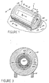
- Figure 1 is a simplified perspective view depicting certain components of an MR system which are associated with an embodiment of the invention.
- Figure 2 is a sectional view taken along lines 2-2 of Figure 1.
- Figure 3 is a sectional view taken along lines 3-3 of Figure 1.
- Figure 4 is a view showing a portion of Figure 2 in greater detail.
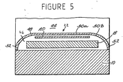
- Figure 5 is a sectional view showing part of the embodiment shown in Figure 2.
- Referring to Figure 1, there is shown a cryostat and
main magnet arrangement 10, of a type which is commonly used in connection with MR high field imaging systems. As is well known by those of skill in the art, the main magnet is positioned around abore 12 and is contained or enclosed within the cryostat. The cryostat maintains the main magnet at an extremely low temperature. Thus, the main magnet is in a superconductive state, to produce a strong, static B0 magnetic field as required for MR imaging. For brevity, cryostat andmain magnet arrangement 10 are hereinafter referred to asmain magnet 10.Metal legs 14 are provided to support themain magnet 10 on afloor 16, when the main magnet and other components of an MR imaging system (not shown) are set up for use. -
Bore 12 ofmain magnet 10 is disposed to receive agradient coil assembly 18, comprising a hollow cylindrical structure. As is well known,gradient coil assembly 18 contains coils (not shown) for generating respective X-, Y-, and Z-gradient fields within the main magnet bore, as are required for MR imaging. The gradient fields are respectively oriented relative to X-, Y-, and Z- coordinate axes, wherein the Z-axis is aligned along the axis of the main magnet bore, in parallel relationship with the direction of the B0 magnetic field. - Referring further to Figure 1, there is shown an
RF coil assembly 20, described hereinafter in further detail, which likewise comprises a hollow cylindrical structure.RF coil assembly 20 has an outside diameter which is selectively less than the inside diameter ofgradient coil assembly 18, and is positioned within the gradient coil assembly, in spaced-apart coaxial relationship therewith.RF coil assembly 20 includes an RF coil or antenna for transmitting and/or receiving RF signals, as required for the MR imaging process. - Figure 1 further shows a cylindrical
inner form 22, comprising a thin-walled tubular member, which is positioned withinRF coil assembly 20 in spaced-apart coaxial relationship and which is described in more detail below with reference to Figures 2 and 5.Tubular member 22 is also positioned in coaxial relationship withgradient coil assembly 18 and with thebore 12 ofmain magnet 10. The space or volume within thetubular member 22 is sized to receive a patient or other subject of MR imaging (not shown). Thus, such volume comprises a patient bore orimaging volume 24, that is, the volume in which the B0 magnetic field, the gradient magnetic fields and the RF signals collectively act to produce MR image data, in accordance with well known MR processes.Tubular member 22 is held in place by fixably attaching itsend portions 22a tomain magnet 10, such as by means ofend caps 26. As best shown by Figure 2,end portions 22a oftubular member 22 are usefully flared outwardly. - Referring to Figure 2 and 3 together, there is shown
gradient coil assembly 18 supported uponmain magnet 10, in spaced-apart relationship, by means ofsupport elements 28.Elements 28 could comprise screws or the like. Alternatively, they could comprise structure which provides vibration isolation betweengradient coil assembly 18 andmain magnet 10. Thesupport elements 28 aligngradient coil assembly 18 withinbore 12 so that the gradient coil assembly and the bore are in coaxial relationship.Gradient coil assembly 18 has a cylindricalinner wall 18a, and asleeve member 32 is joined thereto. - As best shown by Figure 2,
RF coil assembly 20 comprises anRF coil 30 and anRF coil form 34.Coil form 34 comprises a hollow cylindrical structure formed of comparatively stiff material, such as fiber reinforced plastic (FRP), and has aninner surface 34a. The conductors ofRF coil 30 are attached tocoil form 34, suitable means, in close, adjacent relationship withinner surface 34a.RF coil 30 andcoil form 34 are supported inbore 12 and withinsleeve member 32 by means ofscrews 36a and 36b, which are respectively positioned at opposing ends ofRF coil form 34. As described hereinafter in further detail, in connection with Figure 4, each of thescrews 36a and 36b extends betweenRF coil form 34 andsleeve member 32. The screws collectively holdRF coil assembly 20 in spaced-apart relationship withgradient coil assembly 18, to maintain anannular spacing 38 of specified width therebetween, as best shown by Figure 3. Figure 3 also illustrates thatscrews 36a and 36b preferably are grouped in sets, each comprising three screws, which are positioned aroundannular space 38 in equidistant relationship with one another. Thus, the threescrews 36a shown in Figure 3 are oriented at 120° from one another aroundannular space 38. Alternatively, other means besidesscrews 36a and 36b could be used to supportRF coil 30 andRF coil form 34 in spaced-apart relationship withgradient coil assembly 18. - Referring further to Figure 2, there is shown
inner tubular member 22 supported by its flared ends 22a, and byend caps 26, so that it is in spaced-apart and noncontacting relationship withRF coil assembly 20. By providing such spatial separation betweencoil assembly 20 and theinner member 22, it has been found that mechanical motion ofRF coil 30, resulting from induced eddy currents as described above, does not generate significant noise inimaging volume 24.Tubular member 22 is usefully formed of material such as FRP, which tends to act as a further barrier to the transmission of sound. Moreover, it is to be understood thatgradient coil assembly 18 has a mass on the order of 2500 pounds, whereasRF coil assembly 20 has a mass on the order of 50 pounds. Accordingly, vibration or mechanical motion ofRF coil 30 has little effect ongradient coil assembly 18, even if theRF coil assembly 20 is supportably carried on thegradient coil assembly 18, as described above in connection with Figures 2 and 3. - In an MR imaging system which includes the components described herein,
RF coil assembly 20 must be disposed for easy insertion into, as well for as easy removal from, the magnet bore. This is necessary for initial setup, for periodic maintenance, and for other reasons. Accordingly, threaded holes are formed throughRF coil form 34 to accommodate each of thescrews 36a and 36b, the holes being located at the screw positions respectively described above in connection with Figures 2 and 3. Thus, as shown by Figure 4, ahole 40 is provided with threads 42 which are sized to engage thethreads 44 of one of thescrews 36a. The screw may be engaged by a screwdriver or the like (not shown) through the end ofhole 40 which is oriented away fromgradient coil assembly 18. The engagedscrew 36a may be rotated to advance the screw towardgradient coil assembly 18, and to thus bear againstsleeve 32. Thescrew 36a may also be rotated in the opposite direction, to move the screw away fromgradient coil assembly 18, when it is desired to remove theRF coil assembly 20 from the magnet bore. - Referring further to Figure 2, there is shown
gradient coil assembly 18 andRF coil assembly 20 contained within aspace 46.Space 46 is enclosed byinner tubular member 22, end caps 26 andmain magnet 10. Thestructure surrounding space 46 is sealed to be made air-tight. Air is then evacuated fromspace 46, so thatspace 46 becomes a vacuum space. Such vacuum will further impede transmission of noise from theRF coil 30 to theinner tubular member 22 and to theimaging volume 24. - In contrast thereto, the invention is based on the embodiment shown in Figure 5. In this
embodiment tubular member 22 comprises twowalls 50a and 50b, which are positioned in closely spaced parallel relation to provide aspace 48 between them.Seals 52 are provided to sealably enclose thespace 48, so that it is made air-tight. Also, air is removed or evacuated fromspace 48, so that it becomes a vacuum space. Thevacuum space 48 serves as an excellent barrier against the transmission of noise fromRF coil 30 toimaging volume 24. However, thevacuum space 48 is much smaller than thevacuum space 46 described above in connection with Figure 2. Thespace 46 may contain atmosphere or an inert gas. Use of inert gas could be particularly useful for the prevention of arcing within thespace 46.
Claims (4)
- An MR imaging system comprising:a main magnet (10) having a bore (12);a gradient coil assembly (18) having an inner wall (18a) and located within said bore;an RF coil assembly (20) comprising a tubular RF coil form (34) provided with an inner surface (34a), and an RF coil (30) attached to said RF coil form (34), in adjacent relationship with said RF coil form inner surface;mounting structure (32, 36a,36b) extending between said RF coil form (34) and said inner wall of said gradient coil assembly (18) whereby said RF coil (30) and said RF coil form (34) are supported by said gradient coil assembly (18);an inner tubular member (22); andmeans for supporting (22A, 26) said inner tubular member (22) within said bore (12) whereby said tubular member (22) is positioned in spaced-apart relationship with said RF coil and said RF coil form, and whereby said inner tubular member defines a specified portion of the volume of said bore (12), said specified portion comprising an MR imaging volume (24), whereinthe inner tubular member (22) and the main magnet (10) define a space (46) that contains the gradient coil assembly (18) and the RF coil assembly (20), and characterized in that:said inner tubular member (22) is provided with two closely-spaced walls (50a.50b) which are respectively sealed to maintain a vacuum space (48) there between.
- The apparatus of claim 1 wherein said mounting structure comprises:a sleeve member (32) joined to said inner wall (18a) of said gradient coil assembly; anda plurality of adjustable screws (36a,36b) extending between said sleeve member (32) and said RF coil form (34).
- The apparatus of claim 2 wherein:three of said adjustable screws (36a) are positioned around an annular space (38) located between said sleeve member (32) and said RF coil form, (34) in substantially equidistant relationship with one another.
- The apparatus of claim 1 wherein:said space (46) that contains said gradient coil assembly (18) and said RF coil assembly (20) contains atmosphere or an inert gas.
Applications Claiming Priority (2)
| Application Number | Priority Date | Filing Date | Title |
|---|---|---|---|
| US09/376,543 US6252404B1 (en) | 1999-08-18 | 1999-08-18 | Reduced noise RF coil apparatus for MR imaging system |
| US376543 | 1999-08-18 |
Publications (3)
| Publication Number | Publication Date |
|---|---|
| EP1077382A2 EP1077382A2 (en) | 2001-02-21 |
| EP1077382A3 EP1077382A3 (en) | 2003-04-02 |
| EP1077382B1 true EP1077382B1 (en) | 2007-01-17 |
Family
ID=23485436
Family Applications (1)
| Application Number | Title | Priority Date | Filing Date |
|---|---|---|---|
| EP00306988A Expired - Lifetime EP1077382B1 (en) | 1999-08-18 | 2000-08-16 | Reduced noise RF coil apparatus for MR imaging system |
Country Status (4)
| Country | Link |
|---|---|
| US (1) | US6252404B1 (en) |
| EP (1) | EP1077382B1 (en) |
| JP (1) | JP4663076B2 (en) |
| DE (1) | DE60032976T2 (en) |
Families Citing this family (23)
| Publication number | Priority date | Publication date | Assignee | Title |
|---|---|---|---|---|
| DE19940551C1 (en) * | 1999-08-26 | 2001-05-23 | Siemens Ag | Magnetic resonance imaging device with vibration-decoupled outer shell |
| US6414489B1 (en) * | 1999-12-18 | 2002-07-02 | General Electric Company | Apparatus for reducing acoustic noise in an MR imaging system |
| DE10049414C2 (en) * | 2000-10-05 | 2002-09-26 | Siemens Ag | Magnetic resonance device with sound insulation |
| DE10134540C1 (en) | 2001-07-16 | 2003-03-06 | Siemens Ag | Magnetic resonance device with a generator of mechanical vibrations |
| DE10391596B4 (en) * | 2002-04-11 | 2014-09-11 | Siemens Aktiengesellschaft | Encapsulation of a magnetic resonance tomography device for damping low sound frequencies |
| US7068033B2 (en) * | 2003-08-18 | 2006-06-27 | Ge Medical Systems Global Technology Company, Llc | Acoustically damped gradient coil |
| GB2419417B (en) * | 2004-10-20 | 2007-05-16 | Gen Electric | Gradient bore cooling and RF shield |
| JP4664797B2 (en) * | 2005-10-13 | 2011-04-06 | ジーイー・メディカル・システムズ・グローバル・テクノロジー・カンパニー・エルエルシー | MRI equipment |
| US7671593B2 (en) * | 2006-06-15 | 2010-03-02 | General Electric Company | RF body coil with acoustic isolation of conductors |
| JP5416930B2 (en) * | 2007-08-09 | 2014-02-12 | 株式会社東芝 | Magnetic resonance imaging system |
| WO2009031092A1 (en) * | 2007-09-07 | 2009-03-12 | Koninklijke Philips Electronics N.V. | Magnetic resonance examination system with reduced acoustic noise |
| US7936170B2 (en) | 2008-08-08 | 2011-05-03 | General Electric Co. | RF coil and apparatus to reduce acoustic noise in an MRI system |
| GB2465991A (en) * | 2008-12-04 | 2010-06-09 | Siemens Magnet Technology Ltd | Gradient Coil Suspension for MRI Magnet |
| US8710842B2 (en) * | 2011-03-07 | 2014-04-29 | General Electric Company | Apparatus and method to reduce noise in magnetic resonance imaging systems |
| CN103959082A (en) * | 2011-05-10 | 2014-07-30 | 美时医疗控股有限公司 | Cryogenically cooled whole-body rf coil array and mri system having same |
| DE102011082410B4 (en) * | 2011-09-09 | 2015-02-12 | Siemens Aktiengesellschaft | A magnetic resonance apparatus |
| GB2497342B (en) * | 2011-12-08 | 2014-06-18 | Siemens Plc | Vibration isolation for superconducting magnets |
| DE102013202163A1 (en) * | 2013-02-11 | 2014-08-14 | Siemens Aktiengesellschaft | A magnetic resonance apparatus |
| DE102013206557B4 (en) | 2013-04-12 | 2017-03-23 | Siemens Healthcare Gmbh | Magnetic resonance scanner with antenna system |
| DE102013212461B3 (en) | 2013-06-27 | 2014-05-22 | Siemens Aktiengesellschaft | Assembly device for body coil of magnetic resonance apparatus, has adjustment indicators utilized for indicating position of body coil, and fastening device provided with mechanical bearing that is arranged in magnetic resonance apparatus |
| DE102015202165B3 (en) * | 2015-02-06 | 2016-05-04 | Siemens Aktiengesellschaft | Gradient coil assembly, magnetic resonance device and method for damping a Gradientenspulenanordnung |
| JP6660742B2 (en) * | 2016-01-22 | 2020-03-11 | 株式会社日立製作所 | Magnetic resonance imaging equipment |
| CN109642931B (en) | 2016-08-18 | 2022-01-25 | 皇家飞利浦有限公司 | Tunable RF coil for magnetic resonance imaging |
Family Cites Families (7)
| Publication number | Priority date | Publication date | Assignee | Title |
|---|---|---|---|---|
| DE3310160A1 (en) * | 1983-03-21 | 1984-09-27 | Siemens AG, 1000 Berlin und 8000 München | DEVICE FOR GENERATING IMAGES AND LOCALLY RESOLVED SPECTRES OF AN EXAMINATION OBJECT WITH A MAGNETIC CORE RESONANCE |
| NL8303534A (en) * | 1983-10-14 | 1985-05-01 | Philips Nv | NUCLEAR SPIN RESONANCE DEVICE. |
| JPH042643Y2 (en) * | 1985-03-13 | 1992-01-29 | ||
| JPH04332530A (en) * | 1991-05-09 | 1992-11-19 | Toshiba Corp | Inclined magnetic field generating device for mri |
| US5457387A (en) * | 1993-07-06 | 1995-10-10 | Picker International, Inc. | Magnetic resonance imager with removable element RF coil |
| US5592087A (en) * | 1995-01-27 | 1997-01-07 | Picker International, Inc. | Low eddy current radio frequency shield for magnetic resonance imaging |
| EP1046053A1 (en) * | 1998-10-28 | 2000-10-25 | Koninklijke Philips Electronics N.V. | Mri apparatus with a mechanically integrated eddy current shield in the gradient system |
-
1999
- 1999-08-18 US US09/376,543 patent/US6252404B1/en not_active Expired - Fee Related
-
2000
- 2000-08-16 EP EP00306988A patent/EP1077382B1/en not_active Expired - Lifetime
- 2000-08-16 DE DE60032976T patent/DE60032976T2/en not_active Expired - Lifetime
- 2000-08-17 JP JP2000247158A patent/JP4663076B2/en not_active Expired - Fee Related
Also Published As
| Publication number | Publication date |
|---|---|
| JP4663076B2 (en) | 2011-03-30 |
| JP2001178703A (en) | 2001-07-03 |
| EP1077382A3 (en) | 2003-04-02 |
| US6252404B1 (en) | 2001-06-26 |
| EP1077382A2 (en) | 2001-02-21 |
| DE60032976T2 (en) | 2007-11-08 |
| DE60032976D1 (en) | 2007-03-08 |
Similar Documents
| Publication | Publication Date | Title |
|---|---|---|
| EP1077382B1 (en) | Reduced noise RF coil apparatus for MR imaging system | |
| JP4049565B2 (en) | Low noise MRI scanner | |
| JP2002219112A5 (en) | ||
| US6157276A (en) | MRI magnet assembly with non-conductive inner wall | |
| JP4097307B2 (en) | Magnetic resonance imaging scanner sub-assembly | |
| US7141974B2 (en) | Active-passive electromagnetic shielding to reduce MRI acoustic noise | |
| EP0701700A1 (en) | An acoustic screen | |
| US6798201B2 (en) | Magnetic resonance apparatus with sound insulation | |
| JPH0795974A (en) | Magnetic resonance image pickup device | |
| US6501275B1 (en) | Gradient coil arrangement comprising dampening of inner mechanical vibrations | |
| JP4832745B2 (en) | Integrated electronic RF shielding device for MRI magnets | |
| GB2433600A (en) | Device for Magnetic Field Generation | |
| JP2001509726A (en) | Magnetic resonance apparatus with force-optimized gradient coil | |
| US20080315878A1 (en) | Actively Shielded Gradient Coil System Comprising Additional Additional Eddy Current Shield System | |
| US20120313643A1 (en) | Magnetic resonance imaging (mri) device noise dampening system | |
| US7009397B2 (en) | Magnetic resonance apparatus with a gradient coil system structured for reduced noise emission | |
| US7307421B2 (en) | Magnetic resonance imaging device | |
| GB2299673A (en) | MRI magnet with flared opening | |
| US7468606B2 (en) | Vacuum housing for a magnetic resonance apparatus | |
| JP2002325743A (en) | Magnetic circuit structure for mri | |
| EP0982599B1 (en) | Magnetic resonance imaging magnet system | |
| US20070182516A1 (en) | Magnetic resonance imaging device with an active shielding device | |
| US20060006866A1 (en) | Mri system with a conductive member having a damping effect for vibrations | |
| US6717497B2 (en) | Mounting scheme for NMR gradient magnet coils | |
| JP2002052004A (en) | Magnetic resonance imaging apparatus |
Legal Events
| Date | Code | Title | Description |
|---|---|---|---|
| PUAI | Public reference made under article 153(3) epc to a published international application that has entered the european phase |
Free format text: ORIGINAL CODE: 0009012 |
|
| AK | Designated contracting states |
Kind code of ref document: A2 Designated state(s): AT BE CH CY DE DK ES FI FR GB GR IE IT LI LU MC NL PT SE |
|
| AX | Request for extension of the european patent |
Free format text: AL;LT;LV;MK;RO;SI |
|
| PUAL | Search report despatched |
Free format text: ORIGINAL CODE: 0009013 |
|
| AK | Designated contracting states |
Designated state(s): AT BE CH CY DE DK ES FI FR GB GR IE IT LI LU MC NL PT SE Kind code of ref document: A3 Designated state(s): AT BE CH CY DE DK ES FI FR GB GR IE IT LI LU MC NL PT SE |
|
| AX | Request for extension of the european patent |
Extension state: AL LT LV MK RO SI |
|
| RIC1 | Information provided on ipc code assigned before grant |
Ipc: 7G 01R 33/385 A Ipc: 7G 01R 33/34 B |
|
| 17P | Request for examination filed |
Effective date: 20031002 |
|
| AKX | Designation fees paid |
Designated state(s): DE NL |
|
| 17Q | First examination report despatched |
Effective date: 20050114 |
|
| GRAP | Despatch of communication of intention to grant a patent |
Free format text: ORIGINAL CODE: EPIDOSNIGR1 |
|
| GRAS | Grant fee paid |
Free format text: ORIGINAL CODE: EPIDOSNIGR3 |
|
| GRAA | (expected) grant |
Free format text: ORIGINAL CODE: 0009210 |
|
| AK | Designated contracting states |
Kind code of ref document: B1 Designated state(s): DE NL |
|
| REF | Corresponds to: |
Ref document number: 60032976 Country of ref document: DE Date of ref document: 20070308 Kind code of ref document: P |
|
| PLBE | No opposition filed within time limit |
Free format text: ORIGINAL CODE: 0009261 |
|
| STAA | Information on the status of an ep patent application or granted ep patent |
Free format text: STATUS: NO OPPOSITION FILED WITHIN TIME LIMIT |
|
| 26N | No opposition filed |
Effective date: 20071018 |
|
| PGFP | Annual fee paid to national office [announced via postgrant information from national office to epo] |
Ref country code: DE Payment date: 20110830 Year of fee payment: 12 |
|
| PGFP | Annual fee paid to national office [announced via postgrant information from national office to epo] |
Ref country code: NL Payment date: 20110901 Year of fee payment: 12 |
|
| REG | Reference to a national code |
Ref country code: NL Ref legal event code: V1 Effective date: 20130301 |
|
| PG25 | Lapsed in a contracting state [announced via postgrant information from national office to epo] |
Ref country code: NL Free format text: LAPSE BECAUSE OF NON-PAYMENT OF DUE FEES Effective date: 20130301 |
|
| PG25 | Lapsed in a contracting state [announced via postgrant information from national office to epo] |
Ref country code: DE Free format text: LAPSE BECAUSE OF NON-PAYMENT OF DUE FEES Effective date: 20130301 |
|
| REG | Reference to a national code |
Ref country code: DE Ref legal event code: R119 Ref document number: 60032976 Country of ref document: DE Effective date: 20130301 |