EP1077328A1 - Intelligent automatic stoppage and restart of motor vehicle engine - Google Patents
Intelligent automatic stoppage and restart of motor vehicle engine Download PDFInfo
- Publication number
- EP1077328A1 EP1077328A1 EP00117015A EP00117015A EP1077328A1 EP 1077328 A1 EP1077328 A1 EP 1077328A1 EP 00117015 A EP00117015 A EP 00117015A EP 00117015 A EP00117015 A EP 00117015A EP 1077328 A1 EP1077328 A1 EP 1077328A1
- Authority
- EP
- European Patent Office
- Prior art keywords
- vehicle
- bumper
- engine
- controller
- traffic
- Prior art date
- Legal status (The legal status is an assumption and is not a legal conclusion. Google has not performed a legal analysis and makes no representation as to the accuracy of the status listed.)
- Granted
Links
Images




Classifications
-
- B—PERFORMING OPERATIONS; TRANSPORTING
- B60—VEHICLES IN GENERAL
- B60W—CONJOINT CONTROL OF VEHICLE SUB-UNITS OF DIFFERENT TYPE OR DIFFERENT FUNCTION; CONTROL SYSTEMS SPECIALLY ADAPTED FOR HYBRID VEHICLES; ROAD VEHICLE DRIVE CONTROL SYSTEMS FOR PURPOSES NOT RELATED TO THE CONTROL OF A PARTICULAR SUB-UNIT
- B60W10/00—Conjoint control of vehicle sub-units of different type or different function
- B60W10/04—Conjoint control of vehicle sub-units of different type or different function including control of propulsion units
- B60W10/08—Conjoint control of vehicle sub-units of different type or different function including control of propulsion units including control of electric propulsion units, e.g. motors or generators
-
- B—PERFORMING OPERATIONS; TRANSPORTING
- B60—VEHICLES IN GENERAL
- B60K—ARRANGEMENT OR MOUNTING OF PROPULSION UNITS OR OF TRANSMISSIONS IN VEHICLES; ARRANGEMENT OR MOUNTING OF PLURAL DIVERSE PRIME-MOVERS IN VEHICLES; AUXILIARY DRIVES FOR VEHICLES; INSTRUMENTATION OR DASHBOARDS FOR VEHICLES; ARRANGEMENTS IN CONNECTION WITH COOLING, AIR INTAKE, GAS EXHAUST OR FUEL SUPPLY OF PROPULSION UNITS IN VEHICLES
- B60K6/00—Arrangement or mounting of plural diverse prime-movers for mutual or common propulsion, e.g. hybrid propulsion systems comprising electric motors and internal combustion engines
- B60K6/20—Arrangement or mounting of plural diverse prime-movers for mutual or common propulsion, e.g. hybrid propulsion systems comprising electric motors and internal combustion engines the prime-movers consisting of electric motors and internal combustion engines, e.g. HEVs
- B60K6/42—Arrangement or mounting of plural diverse prime-movers for mutual or common propulsion, e.g. hybrid propulsion systems comprising electric motors and internal combustion engines the prime-movers consisting of electric motors and internal combustion engines, e.g. HEVs characterised by the architecture of the hybrid electric vehicle
- B60K6/48—Parallel type
- B60K6/485—Motor-assist type
-
- B—PERFORMING OPERATIONS; TRANSPORTING
- B60—VEHICLES IN GENERAL
- B60W—CONJOINT CONTROL OF VEHICLE SUB-UNITS OF DIFFERENT TYPE OR DIFFERENT FUNCTION; CONTROL SYSTEMS SPECIALLY ADAPTED FOR HYBRID VEHICLES; ROAD VEHICLE DRIVE CONTROL SYSTEMS FOR PURPOSES NOT RELATED TO THE CONTROL OF A PARTICULAR SUB-UNIT
- B60W10/00—Conjoint control of vehicle sub-units of different type or different function
- B60W10/04—Conjoint control of vehicle sub-units of different type or different function including control of propulsion units
- B60W10/06—Conjoint control of vehicle sub-units of different type or different function including control of propulsion units including control of combustion engines
-
- B—PERFORMING OPERATIONS; TRANSPORTING
- B60—VEHICLES IN GENERAL
- B60W—CONJOINT CONTROL OF VEHICLE SUB-UNITS OF DIFFERENT TYPE OR DIFFERENT FUNCTION; CONTROL SYSTEMS SPECIALLY ADAPTED FOR HYBRID VEHICLES; ROAD VEHICLE DRIVE CONTROL SYSTEMS FOR PURPOSES NOT RELATED TO THE CONTROL OF A PARTICULAR SUB-UNIT
- B60W30/00—Purposes of road vehicle drive control systems not related to the control of a particular sub-unit, e.g. of systems using conjoint control of vehicle sub-units
- B60W30/18—Propelling the vehicle
- B60W30/18009—Propelling the vehicle related to particular drive situations
- B60W30/18018—Start-stop drive, e.g. in a traffic jam
-
- F—MECHANICAL ENGINEERING; LIGHTING; HEATING; WEAPONS; BLASTING
- F02—COMBUSTION ENGINES; HOT-GAS OR COMBUSTION-PRODUCT ENGINE PLANTS
- F02N—STARTING OF COMBUSTION ENGINES; STARTING AIDS FOR SUCH ENGINES, NOT OTHERWISE PROVIDED FOR
- F02N11/00—Starting of engines by means of electric motors
- F02N11/08—Circuits specially adapted for starting of engines
- F02N11/0814—Circuits specially adapted for starting of engines comprising means for controlling automatic idle-start-stop
- F02N11/0818—Conditions for starting or stopping the engine or for deactivating the idle-start-stop mode
- F02N11/0833—Vehicle conditions
-
- B—PERFORMING OPERATIONS; TRANSPORTING
- B60—VEHICLES IN GENERAL
- B60K—ARRANGEMENT OR MOUNTING OF PROPULSION UNITS OR OF TRANSMISSIONS IN VEHICLES; ARRANGEMENT OR MOUNTING OF PLURAL DIVERSE PRIME-MOVERS IN VEHICLES; AUXILIARY DRIVES FOR VEHICLES; INSTRUMENTATION OR DASHBOARDS FOR VEHICLES; ARRANGEMENTS IN CONNECTION WITH COOLING, AIR INTAKE, GAS EXHAUST OR FUEL SUPPLY OF PROPULSION UNITS IN VEHICLES
- B60K6/00—Arrangement or mounting of plural diverse prime-movers for mutual or common propulsion, e.g. hybrid propulsion systems comprising electric motors and internal combustion engines
- B60K6/20—Arrangement or mounting of plural diverse prime-movers for mutual or common propulsion, e.g. hybrid propulsion systems comprising electric motors and internal combustion engines the prime-movers consisting of electric motors and internal combustion engines, e.g. HEVs
- B60K6/22—Arrangement or mounting of plural diverse prime-movers for mutual or common propulsion, e.g. hybrid propulsion systems comprising electric motors and internal combustion engines the prime-movers consisting of electric motors and internal combustion engines, e.g. HEVs characterised by apparatus, components or means specially adapted for HEVs
- B60K6/26—Arrangement or mounting of plural diverse prime-movers for mutual or common propulsion, e.g. hybrid propulsion systems comprising electric motors and internal combustion engines the prime-movers consisting of electric motors and internal combustion engines, e.g. HEVs characterised by apparatus, components or means specially adapted for HEVs characterised by the motors or the generators
- B60K2006/268—Electric drive motor starts the engine, i.e. used as starter motor
-
- B—PERFORMING OPERATIONS; TRANSPORTING
- B60—VEHICLES IN GENERAL
- B60W—CONJOINT CONTROL OF VEHICLE SUB-UNITS OF DIFFERENT TYPE OR DIFFERENT FUNCTION; CONTROL SYSTEMS SPECIALLY ADAPTED FOR HYBRID VEHICLES; ROAD VEHICLE DRIVE CONTROL SYSTEMS FOR PURPOSES NOT RELATED TO THE CONTROL OF A PARTICULAR SUB-UNIT
- B60W2540/00—Input parameters relating to occupants
- B60W2540/12—Brake pedal position
-
- B—PERFORMING OPERATIONS; TRANSPORTING
- B60—VEHICLES IN GENERAL
- B60W—CONJOINT CONTROL OF VEHICLE SUB-UNITS OF DIFFERENT TYPE OR DIFFERENT FUNCTION; CONTROL SYSTEMS SPECIALLY ADAPTED FOR HYBRID VEHICLES; ROAD VEHICLE DRIVE CONTROL SYSTEMS FOR PURPOSES NOT RELATED TO THE CONTROL OF A PARTICULAR SUB-UNIT
- B60W2554/00—Input parameters relating to objects
-
- B—PERFORMING OPERATIONS; TRANSPORTING
- B60—VEHICLES IN GENERAL
- B60W—CONJOINT CONTROL OF VEHICLE SUB-UNITS OF DIFFERENT TYPE OR DIFFERENT FUNCTION; CONTROL SYSTEMS SPECIALLY ADAPTED FOR HYBRID VEHICLES; ROAD VEHICLE DRIVE CONTROL SYSTEMS FOR PURPOSES NOT RELATED TO THE CONTROL OF A PARTICULAR SUB-UNIT
- B60W2556/00—Input parameters relating to data
- B60W2556/45—External transmission of data to or from the vehicle
- B60W2556/50—External transmission of data to or from the vehicle of positioning data, e.g. GPS [Global Positioning System] data
-
- F—MECHANICAL ENGINEERING; LIGHTING; HEATING; WEAPONS; BLASTING
- F02—COMBUSTION ENGINES; HOT-GAS OR COMBUSTION-PRODUCT ENGINE PLANTS
- F02D—CONTROLLING COMBUSTION ENGINES
- F02D41/00—Electrical control of supply of combustible mixture or its constituents
- F02D41/02—Circuit arrangements for generating control signals
- F02D41/021—Introducing corrections for particular conditions exterior to the engine
-
- F—MECHANICAL ENGINEERING; LIGHTING; HEATING; WEAPONS; BLASTING
- F02—COMBUSTION ENGINES; HOT-GAS OR COMBUSTION-PRODUCT ENGINE PLANTS
- F02N—STARTING OF COMBUSTION ENGINES; STARTING AIDS FOR SUCH ENGINES, NOT OTHERWISE PROVIDED FOR
- F02N2200/00—Parameters used for control of starting apparatus
- F02N2200/08—Parameters used for control of starting apparatus said parameters being related to the vehicle or its components
- F02N2200/0801—Vehicle speed
-
- F—MECHANICAL ENGINEERING; LIGHTING; HEATING; WEAPONS; BLASTING
- F02—COMBUSTION ENGINES; HOT-GAS OR COMBUSTION-PRODUCT ENGINE PLANTS
- F02N—STARTING OF COMBUSTION ENGINES; STARTING AIDS FOR SUCH ENGINES, NOT OTHERWISE PROVIDED FOR
- F02N2200/00—Parameters used for control of starting apparatus
- F02N2200/12—Parameters used for control of starting apparatus said parameters being related to the vehicle exterior
- F02N2200/123—Information about vehicle position, e.g. from navigation systems or GPS signals
-
- F—MECHANICAL ENGINEERING; LIGHTING; HEATING; WEAPONS; BLASTING
- F02—COMBUSTION ENGINES; HOT-GAS OR COMBUSTION-PRODUCT ENGINE PLANTS
- F02N—STARTING OF COMBUSTION ENGINES; STARTING AIDS FOR SUCH ENGINES, NOT OTHERWISE PROVIDED FOR
- F02N2200/00—Parameters used for control of starting apparatus
- F02N2200/12—Parameters used for control of starting apparatus said parameters being related to the vehicle exterior
- F02N2200/125—Information about other vehicles, traffic lights or traffic congestion
-
- Y—GENERAL TAGGING OF NEW TECHNOLOGICAL DEVELOPMENTS; GENERAL TAGGING OF CROSS-SECTIONAL TECHNOLOGIES SPANNING OVER SEVERAL SECTIONS OF THE IPC; TECHNICAL SUBJECTS COVERED BY FORMER USPC CROSS-REFERENCE ART COLLECTIONS [XRACs] AND DIGESTS
- Y02—TECHNOLOGIES OR APPLICATIONS FOR MITIGATION OR ADAPTATION AGAINST CLIMATE CHANGE
- Y02T—CLIMATE CHANGE MITIGATION TECHNOLOGIES RELATED TO TRANSPORTATION
- Y02T10/00—Road transport of goods or passengers
- Y02T10/10—Internal combustion engine [ICE] based vehicles
- Y02T10/40—Engine management systems
-
- Y—GENERAL TAGGING OF NEW TECHNOLOGICAL DEVELOPMENTS; GENERAL TAGGING OF CROSS-SECTIONAL TECHNOLOGIES SPANNING OVER SEVERAL SECTIONS OF THE IPC; TECHNICAL SUBJECTS COVERED BY FORMER USPC CROSS-REFERENCE ART COLLECTIONS [XRACs] AND DIGESTS
- Y02—TECHNOLOGIES OR APPLICATIONS FOR MITIGATION OR ADAPTATION AGAINST CLIMATE CHANGE
- Y02T—CLIMATE CHANGE MITIGATION TECHNOLOGIES RELATED TO TRANSPORTATION
- Y02T10/00—Road transport of goods or passengers
- Y02T10/60—Other road transportation technologies with climate change mitigation effect
- Y02T10/62—Hybrid vehicles
Definitions
- JP-A 5-1592 discloses an automatic engine stoppage apparatus implementing technique to suppress repeated engine stoppage and restart in bumper-to-bumper traffic. According to this technique, there is an interrogation that vehicle speeds above a predetermined vehicle speed V km/h have been maintained for a predetermined period of time t4. This interrogation is made after performing restart of engine prior to checking if conditions for shutting off the engine are met.
- navigation system 21 is put into operation by turning on engine ignition key, not shown, and it keeps on operating until the engine ignition key is subsequently turned off.
- Navigation system 21 keeps on calculating a vehicle current position and updating in formation as to bumper-to-bumper traffic for use in controller 10.
- a communication line 29 interconnects the navigation system 21 and controller 10. Through the communication line 29, controller 10 can access into navigation system 21 to input in formation on the vehicle current position and on congested road.
Landscapes
- Engineering & Computer Science (AREA)
- Chemical & Material Sciences (AREA)
- Combustion & Propulsion (AREA)
- Mechanical Engineering (AREA)
- Transportation (AREA)
- Automation & Control Theory (AREA)
- General Engineering & Computer Science (AREA)
- Control Of Vehicle Engines Or Engines For Specific Uses (AREA)
- Combined Controls Of Internal Combustion Engines (AREA)
- Navigation (AREA)
- Output Control And Ontrol Of Special Type Engine (AREA)
Abstract
Description
- The present invention relates to the control of an internal combustion engine of a motor vehicle under special conditions of operation. More particularly, the present invention relates to a method and an apparatus for stopping and restarting the operation of the engine.
- Known in the art is an apparatus for arresting a motor vehicle internal combustion engine for the purpose of fuel conservation and reduction of toxic emissions.
- JP-A 8-291725 discloses an apparatus for performing engine shut-off and restart. According to this known apparatus, when a driver depresses a brake pedal and places a manual select lever of an automatic transmission at neutral position under condition of standstill, a controller stops operation of the engine. Subsequently, if the driver places the select lever at drive position with the brake pedal being depressed, the controller restarts the engine.
- The known apparatus fails to include provisions, which prevent repeated engine stoppage at very low vehicle speeds, so that it causes engine stoppage when, in combined city and highway use including bumper-to-bumper traffic, it is counter to the driver's desire. Repeated engine stoppage and restart cause a considerable reduction in the charging level of the vehicle battery.
- JP-A 5-1592 discloses an automatic engine stoppage apparatus implementing technique to suppress repeated engine stoppage and restart in bumper-to-bumper traffic. According to this technique, there is an interrogation that vehicle speeds above a predetermined vehicle speed V km/h have been maintained for a predetermined period of time t4. This interrogation is made after performing restart of engine prior to checking if conditions for shutting off the engine are met.
- This known apparatus is still not satisfactory for a sensitive adaptation to prevailing conditions of the vehicle and in particular tends to shut off the engines when this is counter to the driver's desires or fails to shut off the engine under conditions where it would be justifiable to do so. For example, the above-mentioned condition may not be met if, after it has come to standstill, a vehicle moves off for a few meters at a very low speed toward the preceding vehicle that had stopped in front of a traffic light. Then, the engine will not be stopped automatically upon coming to standstill again at bumper-to-bumper spaced relation to the preceding vehicle.
- An object of the present invention is to provide a method and apparatus for automatic stoppage and restart of an internal combustion engine of a motor vehicle, which is not subject to the abovementioned characteristics of the previously known methods and apparatuses.
- An associated object of the present invention is to provide a method and an apparatus, which prohibits repeated automatic stoppage and restart of a motor vehicle engine to avoid a considerable reduction in the charging level of the vehicle battery under prevailing conditions in combined city and highway use including bumper-to-bumper traffic.
- According to a first aspect of the present invention, there is provided an apparatus for automatic stoppage and restart of an internal combustion engine of a motor vehicle, comprising:
- sensors generating signals; and
- a controller responsive to said signals for conducting automatic stoppage and restart of the engine when the vehicle has come to standstill,
- said controller being operative to determine whether or not the vehicle is on a congested roadway,
- said controller being operative to prohibit conducting automatic stoppage of the engine upon coming to standstill with said determination that the vehicle is on a congested roadway.
-
- According to a second aspect of the present invention, there is provided an apparatus for automatic stoppage and restart of an internal combustion engine of a motor vehicle, comprising:
- sensors generating signals; and
- a controller responsive to said signals for conducting automatic stoppage and restart of the engine when the vehicle has come to standstill,
- said controller being operative to determine whether or not the vehicle has just left a congested roadway,
- said controller being operative to prohibit conducting automatic stoppage of the engine upon coming to standstill with said determination that the vehicle has just left a congested roadway.
-
- According to a third aspect of the present invention, there is provided an apparatus for automatic stoppage and restart of an internal combustion engine of a motor vehicle, comprising:
- sensors generating signals; and
- a controller responsive to said signals for conducting automatic stoppage and restart of the engine when the vehicle has come to standstill,
- said controller being operative to determine whether or not the vehicle is in bumper-to-bumper traffic,
- said controller being operative to prohibit conducting automatic stoppage of the engine upon coming to standstill with said determination that the vehicle is in bumper-to-bumper traffic.
-
- According to a fourth aspect of the present invention, there is provided a method for automatically stopping and restarting operation of an engine of a motor vehicle, comprising:
- detecting a current position of the vehicle;
- providing traffic information whether or not a roadway on which the vehicle is moving is a congested roadway;
- detecting traveling speed of the vehicle;
- conducting stoppage and restart of the engine when the vehicle comes to standstill;
- determining in response to said detected current position and said provided traffic information whether or not the vehicle is on a congested roadway; and
- prohibiting conduction of said stoppage of the engine when the vehicle comes to standstill with said determination that the vehicle is on a congested roadway or has just left a congested roadway.
-
- According to a fifth aspect of the present invention, there is provided a method for automatically stopping and restarting operation of an engine of a motor vehicle, comprising:
- detecting traveling speed of the vehicle;
- calculating a predetermined parameter representative of detected values of traveling speed of the vehicle;
- conducting stoppage and restart of the engine when the vehicle comes to standstill;
- determining in response to said predetermined parameter whether or not the vehicle is in bumper-to-bumper traffic; and
- prohibiting conduction of said stoppage of the engine when the vehicle comes to standstill with said determination that the vehicle is in bumper-to-bumper traffic or has just left bumper-to-bumper traffic.
-
-
- Figure 1 is a schematic view of a vehicle drivetrain employing an intelligent automatic stoppage and restart of a motor vehicle engine implementing the present invention.
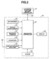
- Figure 2 shows various hardware configurations of a vehicle navigation system in combination with the intelligent automatic stoppage and restart of the motor vehicle engine.
- Figure 3 is a flow chart of a control routine implementing the present invention.
- Figure 4 is a flow chart of a control routine illustrating the first preferred implementation.
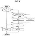
- Figure 5 is a flow chart of a control routine illustrating the second preferred implementation.
- Figure 6 is a flow chart of a control routine illustrating the second preferred implementation.
-
- In Figure 1, a drive train for an automobile includes an
internal combustion engine 1 and a continuously variable transmission (CVT) 3. Thereference numeral 2 designates a motor generator. In this illustrated example,motor generator 2 is disposed betweenengine 1 andCVT 3. In this drivetrain,engine 1 ormotor generator 2 produces drive fed toCVT 3. CVT 3 transmits the drive to adrive shaft 7, which in turn drives the vehicle road wheels, not shown. - The drivetrain is not limited to the illustrated example shown in Figure 1. For example,
engine 1 may be any heat engine such as a gasoline engine and a Diesel engine. CVT 3 is only an example of a transmission that can be used in the drivetrain. For example, an ordinary automatic transmission that has plural discrete gear ratios and a torque converter may replace CVT 3. CVT 3 shown in Figure 1 is of the so-called belt and pulley type. Other types of CVT including a CVT of the so-called conical cone type may be used. -
CVT 3, in this example, has atorque converter 4, a forward and reverse changeover gearing 5, and a pulley unit that includes abelt 6 extending between adriver pulley 6a and afollower pulley 6b. As a source of hydraulic fluid, anoil pump 14 is provided.Engine 1 does not drivepump 14. Instead, pump 14 includes an electric motor that is supplied with electric current always or when need arises. As is well known, a pulley ratio between speed ofdriver pulley 6a and speed offollower pulley 6b is variable. Varying the pulley ratio alters a CVT ratio, that is, a speed ratio between CVT in put shaft speed and CVT output shaft speed. A transmission controller, not shown, determines a target value of an operating parameter, which is variable with CVT ratio, against varying traveling conditions of a vehicle. The transmission controller can adjust primary pressure and secondary pressure applied to driver andfollower pulleys Pump 14 driven by electric motor provides hydraulic pressure needed byCVT 3. - Forward
reverse gearing 5 provides a switch between forward travel and reverse travel.Torque converter 4 provides torque multiplication between its pump side and turbine side. -
Motor generator 2 has a rotor that is coupled directly or via a belt or a chain drive to a crankshaft ofengine 1. Amotor generator controller 12 is provided to rendermotor generator 2 operable as a motor or as a generator. It also controls speed ofmotor generator 2 and torque or electric power. -
Motor generator 2 operates as a motor when more power is needed or whenengine 1 is to be started.Motor generator controller 12 operatesmotor generator 2 as a motor by regulating supply of electric current thereto from avehicle battery 13. In regenerative mode,motor generator controller 12 operatesmotor generator 2 as a generator by regulating supply of electric current frommotor generator 2 to chargebattery 13. - An automatic stop and restart
controller 10 is provided.Controller 10 controls automatic stoppage and restart of theengine 1 upon predetermined conditions being met after the vehicle has come to standstill. - Sensors are provided for
controller 10 to determine appropriate timings of automatic stoppage and restart ofengine 1. The sensors include an engine speed sensor 9, abrake sensor 11, an accelerator pedal (or gas pedal)sensor 15, ashift position sensor 17 and avehicle speed sensor 18. Thevehicle speed sensor 18 detects an operating parameter indicative of traveling speed of the vehicle and generates a vehicle speed signal indicative of the traveling speed.CVT 3 has plural drive positions, i.e., Park, Reverse, Neutral and Drive.Shift position sensor 17 is in the form of an inhibitor switch ofCVT 3 and generates a drive position signal indicative of a current drive position.Accelerator pedal sensor 15 detects depression degree of an accelerator pedal and generates a depression degree signal indicative of the detected depression degree.Brake sensor 15 detects whether or not a brake pedal is depressed and generates a brake signal. Engine speed sensor 9 detects an operating parameter indicative of revolution speed ofengine 1 and generates an engine speed signal indicative of the engine speed. The sensor signals are fed tocontroller 10. - The vehicle has a
navigation system 21. Referring to Figure 2,navigation system 21 includes amagnetic compass 22 as a vehicle orientation sensor, agyroscope 23 to measure an angular rate, avehicle speed sensor 24 that may or may not be identical with thevehicle speed sensor 18, a GPS (Global Positioning System)antenna 25, amap database 26 stored in CD-ROM, anavigation control unit 27, a one or two way data orcommunication link 30 and a user interface that includes adisplay 28.Control unit 27 inputs in formation from the sensors and determines a vehicle current position and also inputs information throughcommunication link 30 to determine where bumper-to-bumper traffic exists. The determined vehicle current position and heading are indicated on a map within thedisplay 28. The determined bumper-to-bumper traffic is indicated on a road or roads on the map as a congested road. - In the present implementation of the present invention,
navigation system 21 is put into operation by turning on engine ignition key, not shown, and it keeps on operating until the engine ignition key is subsequently turned off.Navigation system 21 keeps on calculating a vehicle current position and updating in formation as to bumper-to-bumper traffic for use incontroller 10. Acommunication line 29 interconnects thenavigation system 21 andcontroller 10. Through thecommunication line 29,controller 10 can access intonavigation system 21 to input in formation on the vehicle current position and on congested road. - In order to prevent repeated stoppage and restart of
engine 1,controller 10 prohibits automatic stoppage ofengine 1 when the vehicle comes to standstill in bumper-to-bumper traffic on a congested roadway or immediately after leaving a congested roadway.Controller 10 relies on information fromnavigation system 21 and has logic to determine whether or not the vehicle is on a congested roadway. This logic is also used to determine whether or not the vehicle has just left a congested roadway. - The flow chart of Figure 3 illustrates a control routine for conducting automatic stoppage and restart of
engine 1 implementing the invention.Controller 10 executes this control routine at regular intervals, for example, 10 milliseconds.Controller 10 includes in the usual manner an input/output (I/O) interface, a read only memory (ROM), a random access memory (RAM) and a central processor unit (CPU). A data bus interconnects these components. The ROM stores control programs prepared along the flow chart of Figure 3. - In Figure 3, at
step 101, the CPU ofcontroller 10 determines whether or not predetermined conditions to permit automatic stoppage ofengine 1, i.e., idle stop, are met. - The predetermined conditions include,
- 1 ○ State of charge (SOC) of a vehicle battery falls in a predetermined range, and
- 2 ○ Engine coolant temperature falls in a predetermined engine indicating that engine warming-up has been completed.
-
- If, at
step 101, the CPU determines that both of the above two conditions are met, the control routine proceeds to step 102. Atstep 102, the CPU determines whether or not vehicle speed VSP is zero (= 0 km/h). If this is the case, the control routine proceeds to step 103. Atstep 103, the CPU determines whether or not brake pedal is depressed by checking on the brake signal from thebrake pedal sensor 11. If this is the case, the control routine proceeds to step 104. - At
step 104, the CPU determines whether an automatic stop prohibit (ASP) flag FASP is set (= 1) or reset (= 0). As will be later described along the flow chart of Figure 4, ASP flag FASP is set when the CPU determines that a vehicle is on a congested roadway or the vehicle has just left a congested roadway. That is, when ASP flag FASP = 1, the routine proceeds to step 106 for prohibiting automatic stoppage ofengine 1. Atstep 106, the CPU outputs an engine operation command to permit operation ofengine 1. - If, at
step 104, ASP flag FASP = 0, the routine proceeds to step 105 for conducting automatic stoppage ofengine 1. Atstep 105, the CPU outputs an engine stop command. - If, at
step 101, all of the predetermined conditions are not met, the routine proceeds to step 106. If, atstep 102, the vehicle speed VSP is not zero, the routine proceeds to step 106. If, atstep 102, the brake pedal is not depressed, the routine proceeds to step 106. Atstep 106, the CPU outputs engine operation command. For restartingengine 1, automatic stop and restartcontroller 10 provides an engine restart command tomotor generator controller 12, operatingmotor generator 2 as a motor to startengine 1. - The flow chart of Figure 4 illustrates a control routine implementing the present invention. The CPU executes this control routine at regular intervals, for example, 10 milliseconds. The control routine includes logic to determine whether or not a vehicle is on a congested roadway and whether or not the vehicle has just left a congested roadway.
- At
step 111, the CPU inputs information on vehicle current position and in formation on traffic fromnavigation control unit 27 and determines whether or not a vehicle is on a congested roadway. If this is the case, the routine proceeds to step 112 and then to step 113. Atstep 112, the CPU sets a congested roadway (CR) flag FCR (FCR = 1). Atstep 113, the CPU sets ASP flag FASP (FASP = 1). Both of the flags FCR and FASP are initially reset and thus equal to zero, respectively. - If, at
step 111, the CPU determines that the vehicle is not on a congested roadway, the routine proceeds to step 114. Atstep 114, the CPU resets CR flag FCR. Immediately after the moment when there is a shift of CR flag FCR from 1 to 0, the CPU starts measuring time elapsed from the moment (steps 115 to 117). This moment represents when a vehicle has just left a congested roadway. Atstep 115, the CPU determines whether or not there is a shift of CR flag FCR from 1 to 0 by comparing the current 0 level of CR flag FCR with the previous level thereof. If this is the case, the routine proceeds to step 116. Atstep 116, the CPU sets a timer t ready for action (t = 0). If, atstep 114, the current 0 level of CR flag FCR is equal to the previous level thereof, the routine proceeds to step 117. Atstep 117, the CPU performs increment of the timer t by one. - After
step step 118, the CPU determines whether or not the timer t is greater than a predetermined value T. The predetermined value T represents a period of time on which a decision is made whether or not the vehicle has left a congested roadway. In this example, the predetermined value represents 1 minute. If, atstep 118, t < T, the routine proceeds to step 113. Atstep 113, the CPU sets ASP flag FASP (FASP = 1). - If, at
step 118, t ≧ T, the routine proceeds to step 119 where the CPU resets ASP flag FASP (FASP = 0). - The preceding description clearly indicates that ASP flag FASP allows engine to keep on idling when vehicle comes to stationary on a congested roadway or immediately after the vehicle has left a congested roadway.
- The preferred implementation has used information on current vehicle position and information on traffic from
navigation system 21, thus making it easy to prohibit automatic stoppage ofengine 1 when vehicle is on a congested roadway or immediately after vehicle has left a congested roadway. - Referring to Figures 5 and 6, description on a second preferred implementation of the present invention is made. This second implementation is substantially the same as the first implementation, but a stop-and-go (SAG) flag FSAG is used in the place of CR flag FCR in determining ASP flag FASP. The flow chart of Figure 5 illustrates a control routine implementing the present invention. The CPU executes this control routine at regular intervals, for example, 10 milliseconds, to determine ASP flag FASP. The flow chart of Figure 6 illustrates a control routine implementing the present invention. The CPU executes this control routine at regular intervals, for example, 10 milliseconds, to determine SAG flag FSAG. Accordingly, the second preferred implementation is different from the first preferred implementation in that the control routines of Figures 5 and 6 have replaced the control routine of Figure 4.
- The same reference numerals are used throughout Figures 4 and 5 to designate like steps to facilitate understanding of similarity between them.
- In Figure 5, at
step 121, the CPU determines whether or not SAG flag FSAG is set (FSAG = 1). If this is the case, the routine proceeds to step 113. Atstep 113, the CPU sets ASP flag FASP. If, atstep 121, SAG flag FSAG is reset (FSAG = 0), the routine proceeds to step 122. Atstep 122, the CPU determines whether or not there is a shift of SAG flag FSAG from 1 to 0 by comparing the current 0 level of SAG flag FSAG with the previous level thereof. If this is the case, the routine proceeds to step 116. Atstep 116, the CPU sets a timer t ready for action (t = 0). If, atstep 122, the current 0 level of SAG flag FSAG is equal to the previous level thereof, the routine proceeds to step 117. Atstep 117, the CPU performs increment of the timer t by one. - After
step step 118, the CPU determines whether or not the timer t is greater than or equal to a predetermined value T. In this example, the predetermined value represents 1 minute. If, atstep 118, t < T, the routine proceeds to step 113. Atstep 113, the CPU sets ASP flag FASP (FASP = 1). - If, at
step 118, t ≧ T, the routine proceeds to step 119 where the CPU resets ASP flag FASP (FASP = 0). - The flow chart of Figure 6 illustrates how to determine SAG flag FSAG.
- The first preferred implementation is operable on information from
vehicle navigation system 21. According to the second preferred implementation, the estimation whether or not a vehicle is in bumper-to-bumper traffic is made on information derived from vehicle speed sensor 18 (see Figure 1). Thus, the second preferred implementation does not require a navigation system and finds its application to vehicles that are not equipped with a navigation system. - In Figure 6, at
step 131, the CPU determines whether or not SAG flag FSAG is set (FSAG = 1). If, atstep 131, FSAG = 0, the routine proceeds to step 132 and onwards. Atstep 132, the CPU determines whether or not an average vehicle speed VSPAV is less than or equal to a first predetermined vehicle speed value V1 (VSPAV ≦ V1). The first predetermined vehicle speed value V1 represents a vehicle speed, for example, 10 km/h, which is not to be exceeded when vehicle is in bumper-to-bumper traffic. If, atstep 132, VSPAV > V1, the routine comes to an end point, thus leaving SAG flag FSAG as it is (FSAG = 0). - If, at
step 132, the CPU determines that VSPAV ≦ V1, the routine proceeds to step 133. Atstep 133, the CPU determines whether or not the current determination atstep 132 that VSPAV ≦ V1 is the first time by comparing the current determination atstep 132 with the previous determination atstep 132. If, atstep 133, the current determination is the first time, the routine proceeds to step 134. Atstep 134, the CPU sets a first timer t1 ready for action (t1 = 0). If, atstep 133, the current determination is not the first time and thus the second time and onwards, the routine proceeds to step 135. Atstep 135, the CPU performs increment of the first timer t1 by one. - After
step step 136, the CPU determines whether or not the first timer t1 is greater than or equal to a predetermined value T1 (t1 ≧ T1). The predetermined value T1 represents a period of time, for example, 5 minutes, which is considered to be sufficiently long after the moment when the determination that VSPAV ≦ V1 was made at the first time to determine that vehicle is traveling at high speeds. If, atstep 136, t1 ≧ T1, the routine proceeds to step 137 because this is the case when vehicle is traveling at high speeds. Atstep 137, the CPU sets the high speed travelling flag FHST (FHST = 1). - If, at
step 136, t1 < T1, the routine proceeds to the end point, leaving SAG flag FSAG as it is (FSAG = 0). This means that SAG flag FSAG stays at the level of 0 as long as t1 is shorter than T1 after the moment when the determination that VSPAV ≦ V1 was made at the first time. - If, at
step 131, FSAG = 1, the routine proceeds to step 138 and onwards. Atstep 138, the CPU determines whether or not average vehicle speed VSPAV is greater than or equal to a second predetermined vehicle speed value V2 (VSPAV ≧ V2). The second predetermined vehicle speed value V2 represents a vehicle speed, for example, 30 km/h, which is to be exceeded when a vehicle has left bumper-to-bumper traffic. If, atstep 138, VSPAV < V2, the routine comes to an end point, thus leaving the flag FSAG as it is (FSAG = 1). - If, at
step 138, the CPU determines that VSPAV ≧ V2, the routine proceeds to step 139. Atstep 139, the CPU determines whether or not the current determination atstep 138 that VSPAV ≧ V2 is the first time by comparing the current determination atstep 138 with the previous determination atstep 138. If, atstep 139, the current determination is the first time, the routine proceeds to step 140. Atstep 140, the CPU sets a second timer t2 ready for action (t2 = 0). If, atstep 139, the current determination is not the first time and thus the second time and onwards, the routine proceeds to step 141. Atstep 141, the CPU performs increment of the second timer t2 by one. - After
step step 142, the CPU determines whether or not the second timer t2 is greater than or equal to a predetermined value T2 (t2 ≧ T2). The predetermined value T2 represents a period of time, for example, 1 minute, which is considered to be sufficiently long after the moment when the determination that VSPAV ≧ V2 was made at the first time to determine that vehicle has left bumper-to-bumper traffic. If, atstep 142, t2 ≧ T2, the routine proceeds to step 143. Atstep 143, the CPU resets SAG flag FSAG (FSAG = 0). - If, at
step 142, t2 < T2, the routine proceeds to the end point, leaving SAG flag FSAG as it is (FSAG = 1). This means that SAG flag FSAG stays at the level of 1 as long as t2 is shorter than T2 after the moment when the determination that VSPAV ≧ V2 was made at the first time. - The average vehicle speed VSPAV can be given by calculating weighted average or simple average of vehicle speed VSP indicated by the vehicle speed signal generated by
vehicle speed sensor 18. The use of such average of vehicle speed is advantageous in removing effect of instantaneous acceleration/deceleration upon evaluating whether or not a vehicle is in bumper-to-bumper traffic. - Let us now assume that the vehicle keeps on travelling at average speed VSPAV that is less than V1 for a period of time longer T1. In this case, the vehicle is in bumper-to-bumper traffic, so that SAG flag FSAG is equal to 1 (FSAG = 1). Under this condition, if a brake pedal is applied to bring the vehicle to stationary, the average vehicle speed VSPAV drops to 0 (km/h). SAG flag FSAG is equal to 1, prohibiting the automatic stoppage of
engine 1. Accordingly, repeated automatic stoppage and restart will not take place while the vehicle is in bumper-to-bumper traffic because SAG flag FSAG is equal to 1. In this manner, a considerable reduction in charging level of vehicle battery is prevented. - Let us consider the case where a vehicle can speed up for a relatively short period of time while traveling in bumper-to-bumper traffic. This is the case where the average vehicle speed VSPAV exceeds V2 for a period of time shorter than T2. Accordingly, SAG flag FSAG remains equal to 1, prohibiting automatic stoppage of engine for vehicle battery energy conservation.
- Let us next consider the case where a vehicle comes to a standstill in normal traffic and moves off again for traveling in normal traffic. This is the case where the average speed VSPAV drops below V1 for a period of time shorter than T1. Accordingly, flag FSAG remains equal to 0, allowing automatic stoppage and restart of engine for fuel conservation and reduction in toxic emissions.
- In the preferred implementations, T represented 1 minute, T1 represented 5 minutes, V1 represented 10 km/h, T2 represented 1 minute, and V2 represented 30 km/h. These predetermined values are subject to variations in accordance with types of engine and types of vehicle. Appropriate values to such predetermined values can be determined by matching.
- In the first preferred implementation, the present invention is implemented with such navigation system having GPS antenna. The present in vent/on may be implemented with other types of navigation systems, for example, a navigation system utilizing road traffic in formation beacon.
- While the present invention has been particularly described in conjunction with the preferred implementations, it is evident that many alternatives, modifications and variations will be apparent to those skilled in the art in light of the foregoing description. It is therefore contemplated that the appended claims will embrace any such alternatives, modifications and variations as falling within the true scope and spirit of the present invention
- The content of disclosure of Japanese Patent Application No. 11-229670, filed August 16, 1999 is hereby incorporated by reference in its entirety.
Claims (9)
- An apparatus for automatic stoppage and restart of an internal combustion engine of a motor vehicle, comprising:sensors generating signals; anda controller responsive to said signals for conducting automatic stoppage and restart of the engine when the vehicle has come to standstill,said controller being operative to determine whether or not the vehicle is on a congested roadway,said controller being operative to prohibit conducting automatic stoppage of the engine upon coming to standstill with said determination that the vehicle is on a congested roadway.
- An apparatus for automatic stoppage and restart of an internal combustion engine of a motor vehicle, comprising:sensors generating signals; anda controller responsive to said signals for conducting automatic stoppage and restart of the engine when the vehicle has come to standstill,said controller being operative to determine whether or not the vehicle has just left a congested roadway,said controller being operative to prohibit conducting automatic stoppage of the engine upon coming to standstill with said determination that the vehicle has just left a congested roadway.
- An apparatus for automatic stoppage and restart of an internal combustion engine of a motor vehicle, comprising:sensors generating signals; anda controller responsive to said signals for conducting automatic stoppage and restart of the engine when the vehicle has come to standstill,said controller being operative to determine whether or not the vehicle is in bumper-to-bumper traffic,said controller being operative to prohibit conducting automatic stoppage of the engine upon coming to standstill with said determination that the vehicle is in bumper-to-bumper traffic.
- The apparatus as claimed in claim 1, further comprising a navigation system, including a map database, for generating vehicle current position information and traffic information of every roadways, and wherein said controller determines based on said current position information and said traffic information whether or not the vehicle is on a congested roadway.
- The apparatus as claimed in claim 2, further comprising a navigation system, including a map database, for generating vehicle current position information and traffic information of every roadways, and wherein said controller determines based on said current position information and said traffic information whether or not the vehicle has just left a congested roadway.
- The apparatus as claimed in claim 3,
wherein said controller is operative to determine that the vehicle is in bumper-to-bumper traffic after a predetermined parameter indicative of traveling speed of the vehicle has stayed less than or equal to a first predetermined value for at least a first predetermined period of time, wherein said controller is operative to keep on determining that the vehicle is in bumper-to-bumper traffic after said predetermined parameter has exceeded a second predetermined value that is higher than said first predetermined value but has stayed greater than said second predetermined value for a period of time less than a second predetermined period of time if determination that the vehicle was in bumper-to-bumper traffic was made,
and wherein said controller is operative to determine that the vehicle is not in bumper-to-bumper traffic after said predetermined parameter has stayed less than or equal to a first predetermined value for a period of time less than said first predetermined period of time, wherein said controller is operative to determine that the vehicle is not in bumper-to-bumper traffic after said predetermined parameter has stayed greater than said second predetermined value for at least second predetermined period of time. - The apparatus as claimed in claim 6, wherein said predetermined parameter the average of measures of vehicle speed.
- A method for automatically stopping and restarting operation of an engine of a motor vehicle, comprising:detecting a current position of the vehicle;providing traffic information whether or not a roadway on which the vehicle is moving is a congested roadway;detecting traveling speed of the vehicle;conducting stoppage and restart of the engine when the vehicle comes to standstill;determining in response to said detected current position and said provided traffic information whether or not the vehicle is on a congested roadway; andprohibiting conduction of said stoppage of the engine when the vehicle comes to standstill with said determination that the vehicle is on a congested roadway or has just left a congested roadway.
- A method for automatically stopping and restarting operation of an engine of a motor vehicle, comprising:detecting traveling speed of the vehicle;calculating a predetermined parameter representative of detected values of traveling speed of the vehicle;conducting stoppage and restart of the engine when the vehicle comes to standstill;determining in response to said predetermined parameter whether or not the vehicle is in bumper-to-bumper traffic; andprohibiting conduction of said stoppage of the engine when the vehicle comes to standstill with said determination that the vehicle is in bumper-to-bumper traffic or has just left bumper-to-bumper traffic.
Applications Claiming Priority (2)
| Application Number | Priority Date | Filing Date | Title |
|---|---|---|---|
| JP11229670A JP2001055939A (en) | 1999-08-16 | 1999-08-16 | Automatic stop / restart system for vehicle engine |
| JP22967099 | 1999-08-16 |
Publications (2)
| Publication Number | Publication Date |
|---|---|
| EP1077328A1 true EP1077328A1 (en) | 2001-02-21 |
| EP1077328B1 EP1077328B1 (en) | 2003-03-19 |
Family
ID=16895849
Family Applications (1)
| Application Number | Title | Priority Date | Filing Date |
|---|---|---|---|
| EP00117015A Expired - Lifetime EP1077328B1 (en) | 1999-08-16 | 2000-08-08 | Intelligent automatic stoppage and restart of motor vehicle engine |
Country Status (3)
| Country | Link |
|---|---|
| EP (1) | EP1077328B1 (en) |
| JP (1) | JP2001055939A (en) |
| DE (1) | DE60001695T2 (en) |
Cited By (9)
| Publication number | Priority date | Publication date | Assignee | Title |
|---|---|---|---|---|
| EP1302359A1 (en) * | 2001-10-13 | 2003-04-16 | Ford Global Technologies, Inc., A subsidiary of Ford Motor Company | Vehicle engine automatic start/stop control method |
| DE10234064A1 (en) * | 2002-07-26 | 2004-02-12 | Audi Ag | Motor vehicle with automatic self acceleration or retardation has system control for starting and stopping and combines starter and drive systems |
| EP1396622A4 (en) * | 2001-06-14 | 2006-04-05 | Toyota Motor Co Ltd | DEVICE AND METHOD FOR THE AUTOMATIC SHUT-OFF CONTROL OF A COMBUSTION ENGINE FOR A VEHICLE |
| DE102008020184A1 (en) * | 2008-04-22 | 2009-11-19 | Continental Automotive Gmbh | Method for controlling stop or start function of internal combustion engine of vehicle, particularly passenger car, involves determining position of clutch with help of two sensors, where sensors are assigned to clutch pedal |
| CN105405286A (en) * | 2015-12-04 | 2016-03-16 | 广州汽车集团股份有限公司 | Engine intelligent starting-stopping control method and engine intelligent starting-stopping system |
| CN107531240A (en) * | 2015-02-02 | 2018-01-02 | 标致雪铁龙汽车股份有限公司 | The control method for being automatically stopped and resetting function of explosive motor |
| US11300091B2 (en) | 2020-08-03 | 2022-04-12 | Ford Global Technologies, Llc | Methods and system for inhibiting automatic engine stopping |
| US11326571B2 (en) | 2020-08-03 | 2022-05-10 | Ford Global Technologies, Llc | Methods and system for adaptively switching an engine starting device |
| CN120056960A (en) * | 2025-04-28 | 2025-05-30 | 成都赛力斯科技有限公司 | Range extender control method and electronic equipment |
Families Citing this family (14)
| Publication number | Priority date | Publication date | Assignee | Title |
|---|---|---|---|---|
| JP2004232538A (en) * | 2003-01-30 | 2004-08-19 | Nissan Motor Co Ltd | Automatic stop / restart control system for vehicle engine |
| US7809487B2 (en) * | 2007-09-14 | 2010-10-05 | Ford Global Technologies, Llc | Method and system for controlling a motive power system of an automotive vehicle |
| KR20090100497A (en) * | 2008-03-20 | 2009-09-24 | 한국전자통신연구원 | Idle control system and its control method |
| DE102008031340A1 (en) * | 2008-07-02 | 2010-01-07 | Bayerische Motoren Werke Aktiengesellschaft | Method for influencing engine stop mechanism of motor vehicle, involves switching off engine automatically, when predetermined operating conditions are achieved for predetermined time |
| DE102009046829A1 (en) | 2009-11-18 | 2011-05-19 | Robert Bosch Gmbh | Method for controlling motor of driving vehicle, involves receiving road characteristic information or speed information by interface, where road characteristic information represents information over gradient of road section |
| DE102010027937A1 (en) | 2010-04-20 | 2011-10-20 | Robert Bosch Gmbh | Start-stop system for a motor vehicle |
| DE102010041104B4 (en) * | 2010-09-21 | 2020-07-30 | Bayerische Motoren Werke Aktiengesellschaft | Method for automatically switching off an internal combustion engine |
| KR101874314B1 (en) * | 2012-10-23 | 2018-07-05 | 콘티넨탈 오토모티브 시스템 주식회사 | Control method for idle stop and go system according to traffic condition |
| JP2015194118A (en) * | 2014-03-31 | 2015-11-05 | 株式会社デンソー | Idling stop control device |
| JP6451564B2 (en) * | 2015-09-09 | 2019-01-16 | 株式会社デンソー | Engine control device |
| KR101795177B1 (en) * | 2015-12-10 | 2017-11-07 | 현대자동차주식회사 | Apparatus and Method for controlling auto-off of Idle Stop and Go function |
| JP2017218961A (en) * | 2016-06-07 | 2017-12-14 | いすゞ自動車株式会社 | Idling stop prohibition device and program |
| JP7003530B2 (en) * | 2017-09-26 | 2022-01-20 | トヨタ自動車株式会社 | Hybrid car |
| JP7578842B2 (en) * | 2021-09-30 | 2024-11-06 | 本田技研工業株式会社 | Saddle-type vehicle |
Citations (4)
| Publication number | Priority date | Publication date | Assignee | Title |
|---|---|---|---|---|
| JPH051592A (en) * | 1991-01-31 | 1993-01-08 | Suzuki Motor Corp | Engine automatic stop start control device |
| JPH08291725A (en) * | 1995-04-20 | 1996-11-05 | Hino Motors Ltd | Automatic stopping and restarting device for engine of vehicle |
| JPH09144587A (en) * | 1995-11-24 | 1997-06-03 | Denso Corp | Vehicle engine overheat prevention device |
| DE19600734A1 (en) * | 1996-01-11 | 1997-07-17 | Zahnradfabrik Friedrichshafen | Motor vehicle system control method w.r.t. external conditions, location etc. |
-
1999
- 1999-08-16 JP JP11229670A patent/JP2001055939A/en active Pending
-
2000
- 2000-08-08 DE DE60001695T patent/DE60001695T2/en not_active Expired - Fee Related
- 2000-08-08 EP EP00117015A patent/EP1077328B1/en not_active Expired - Lifetime
Patent Citations (4)
| Publication number | Priority date | Publication date | Assignee | Title |
|---|---|---|---|---|
| JPH051592A (en) * | 1991-01-31 | 1993-01-08 | Suzuki Motor Corp | Engine automatic stop start control device |
| JPH08291725A (en) * | 1995-04-20 | 1996-11-05 | Hino Motors Ltd | Automatic stopping and restarting device for engine of vehicle |
| JPH09144587A (en) * | 1995-11-24 | 1997-06-03 | Denso Corp | Vehicle engine overheat prevention device |
| DE19600734A1 (en) * | 1996-01-11 | 1997-07-17 | Zahnradfabrik Friedrichshafen | Motor vehicle system control method w.r.t. external conditions, location etc. |
Non-Patent Citations (3)
| Title |
|---|
| PATENT ABSTRACTS OF JAPAN vol. 017, no. 263 (M - 1415) 24 May 1993 (1993-05-24) * |
| PATENT ABSTRACTS OF JAPAN vol. 1997, no. 03 31 March 1997 (1997-03-31) * |
| PATENT ABSTRACTS OF JAPAN vol. 1997, no. 10 31 October 1997 (1997-10-31) * |
Cited By (13)
| Publication number | Priority date | Publication date | Assignee | Title |
|---|---|---|---|---|
| EP1396622A4 (en) * | 2001-06-14 | 2006-04-05 | Toyota Motor Co Ltd | DEVICE AND METHOD FOR THE AUTOMATIC SHUT-OFF CONTROL OF A COMBUSTION ENGINE FOR A VEHICLE |
| US7099768B2 (en) | 2001-06-14 | 2006-08-29 | Toyota Jidosha Kabushiki Kaisha | Automatic shutdown control for vehicular internal combustion |
| EP1302359A1 (en) * | 2001-10-13 | 2003-04-16 | Ford Global Technologies, Inc., A subsidiary of Ford Motor Company | Vehicle engine automatic start/stop control method |
| US6830534B2 (en) | 2001-10-13 | 2004-12-14 | Ford Global Technologies, Llc | Method for controlling the internal combustion engine of a motor vehicle with a stop/start function |
| DE10234064A1 (en) * | 2002-07-26 | 2004-02-12 | Audi Ag | Motor vehicle with automatic self acceleration or retardation has system control for starting and stopping and combines starter and drive systems |
| DE10234064B4 (en) * | 2002-07-26 | 2008-01-03 | Audi Ag | motor vehicle |
| DE102008020184A1 (en) * | 2008-04-22 | 2009-11-19 | Continental Automotive Gmbh | Method for controlling stop or start function of internal combustion engine of vehicle, particularly passenger car, involves determining position of clutch with help of two sensors, where sensors are assigned to clutch pedal |
| CN107531240A (en) * | 2015-02-02 | 2018-01-02 | 标致雪铁龙汽车股份有限公司 | The control method for being automatically stopped and resetting function of explosive motor |
| CN105405286A (en) * | 2015-12-04 | 2016-03-16 | 广州汽车集团股份有限公司 | Engine intelligent starting-stopping control method and engine intelligent starting-stopping system |
| US11300091B2 (en) | 2020-08-03 | 2022-04-12 | Ford Global Technologies, Llc | Methods and system for inhibiting automatic engine stopping |
| US11326571B2 (en) | 2020-08-03 | 2022-05-10 | Ford Global Technologies, Llc | Methods and system for adaptively switching an engine starting device |
| US11649795B2 (en) | 2020-08-03 | 2023-05-16 | Ford Global Technologies, Llc | Methods and system for inhibiting automatic engine stopping |
| CN120056960A (en) * | 2025-04-28 | 2025-05-30 | 成都赛力斯科技有限公司 | Range extender control method and electronic equipment |
Also Published As
| Publication number | Publication date |
|---|---|
| JP2001055939A (en) | 2001-02-27 |
| DE60001695T2 (en) | 2003-10-16 |
| EP1077328B1 (en) | 2003-03-19 |
| DE60001695D1 (en) | 2003-04-24 |
Similar Documents
| Publication | Publication Date | Title |
|---|---|---|
| EP1077328B1 (en) | Intelligent automatic stoppage and restart of motor vehicle engine | |
| JP4858039B2 (en) | Vehicle control device | |
| EP2928745B1 (en) | Hybrid electric vehicle control system and method | |
| KR100362604B1 (en) | Controlling apparatus and method of automobile | |
| KR100951675B1 (en) | Motor vehicle and control method of motor vehicle | |
| JP3903628B2 (en) | Control device for hybrid vehicle | |
| US6283086B1 (en) | Engine control apparatus | |
| US11608806B2 (en) | Control system for vehicle | |
| EP1074417B1 (en) | Start-stop engine control apparatus for a hybrid vehicle | |
| US10611376B2 (en) | Methods and system for decelerating a vehicle | |
| US9605614B2 (en) | Vehicle control system | |
| CN110091865A (en) | Hybrid power system | |
| JP3931457B2 (en) | Charge control device for hybrid vehicle | |
| US20140167944A1 (en) | Display device | |
| US20160101775A1 (en) | Delay changing on/off state of engine during cruise control in a hybrid vehicle | |
| US20180209355A1 (en) | Engine control method and vehicle traveling control device | |
| JP2017020460A (en) | Coasting travel control method and coasting travel control device | |
| US20020056583A1 (en) | Apparatus for controlling vehicle driving force | |
| JP3758419B2 (en) | Idle stop vehicle | |
| EP1069311B1 (en) | Intelligent automatic engine stop and restart system for land vehicles | |
| US11667290B2 (en) | Method for reducing vehicle fuel consumption during coasting | |
| CN116624304A (en) | Method and system for disabling automatic engine shutdown | |
| JP3750240B2 (en) | Vehicle control device | |
| JPH08337135A (en) | Stop control device for automobile | |
| JP2006288071A (en) | Vehicle control device and vehicle control method |
Legal Events
| Date | Code | Title | Description |
|---|---|---|---|
| PUAI | Public reference made under article 153(3) epc to a published international application that has entered the european phase |
Free format text: ORIGINAL CODE: 0009012 |
|
| 17P | Request for examination filed |
Effective date: 20000808 |
|
| AK | Designated contracting states |
Kind code of ref document: A1 Designated state(s): DE FR GB |
|
| AX | Request for extension of the european patent |
Free format text: AL;LT;LV;MK;RO;SI |
|
| 17Q | First examination report despatched |
Effective date: 20010518 |
|
| AKX | Designation fees paid |
Free format text: DE FR GB |
|
| GRAH | Despatch of communication of intention to grant a patent |
Free format text: ORIGINAL CODE: EPIDOS IGRA |
|
| GRAH | Despatch of communication of intention to grant a patent |
Free format text: ORIGINAL CODE: EPIDOS IGRA |
|
| GRAA | (expected) grant |
Free format text: ORIGINAL CODE: 0009210 |
|
| AK | Designated contracting states |
Designated state(s): DE FR GB |
|
| REG | Reference to a national code |
Ref country code: GB Ref legal event code: FG4D |
|
| REF | Corresponds to: |
Ref document number: 60001695 Country of ref document: DE Date of ref document: 20030424 Kind code of ref document: P |
|
| ET | Fr: translation filed | ||
| PLBE | No opposition filed within time limit |
Free format text: ORIGINAL CODE: 0009261 |
|
| STAA | Information on the status of an ep patent application or granted ep patent |
Free format text: STATUS: NO OPPOSITION FILED WITHIN TIME LIMIT |
|
| 26N | No opposition filed |
Effective date: 20031222 |
|
| PGFP | Annual fee paid to national office [announced via postgrant information from national office to epo] |
Ref country code: GB Payment date: 20060802 Year of fee payment: 7 |
|
| PGFP | Annual fee paid to national office [announced via postgrant information from national office to epo] |
Ref country code: DE Payment date: 20060803 Year of fee payment: 7 |
|
| PGFP | Annual fee paid to national office [announced via postgrant information from national office to epo] |
Ref country code: FR Payment date: 20060808 Year of fee payment: 7 |
|
| GBPC | Gb: european patent ceased through non-payment of renewal fee |
Effective date: 20070808 |
|
| REG | Reference to a national code |
Ref country code: FR Ref legal event code: ST Effective date: 20080430 |
|
| PG25 | Lapsed in a contracting state [announced via postgrant information from national office to epo] |
Ref country code: DE Free format text: LAPSE BECAUSE OF NON-PAYMENT OF DUE FEES Effective date: 20080301 |
|
| PG25 | Lapsed in a contracting state [announced via postgrant information from national office to epo] |
Ref country code: FR Free format text: LAPSE BECAUSE OF NON-PAYMENT OF DUE FEES Effective date: 20070831 |
|
| PG25 | Lapsed in a contracting state [announced via postgrant information from national office to epo] |
Ref country code: GB Free format text: LAPSE BECAUSE OF NON-PAYMENT OF DUE FEES Effective date: 20070808 |