EP1077326A2 - Injecteur à combustible - Google Patents
Injecteur à combustible Download PDFInfo
- Publication number
- EP1077326A2 EP1077326A2 EP00306751A EP00306751A EP1077326A2 EP 1077326 A2 EP1077326 A2 EP 1077326A2 EP 00306751 A EP00306751 A EP 00306751A EP 00306751 A EP00306751 A EP 00306751A EP 1077326 A2 EP1077326 A2 EP 1077326A2
- Authority
- EP
- European Patent Office
- Prior art keywords
- valve needle
- fuel
- seating
- bore
- sleeve member
- Prior art date
- Legal status (The legal status is an assumption and is not a legal conclusion. Google has not performed a legal analysis and makes no representation as to the accuracy of the status listed.)
- Withdrawn
Links
- 239000000446 fuel Substances 0.000 title claims abstract description 122
- 230000015572 biosynthetic process Effects 0.000 claims description 2
- 238000005755 formation reaction Methods 0.000 claims description 2
- 238000002347 injection Methods 0.000 description 9
- 239000007924 injection Substances 0.000 description 9
- 230000006835 compression Effects 0.000 description 7
- 238000007906 compression Methods 0.000 description 7
- 238000002485 combustion reaction Methods 0.000 description 4
- 239000007921 spray Substances 0.000 description 3
- 230000004323 axial length Effects 0.000 description 2
- 230000000694 effects Effects 0.000 description 2
- 230000003247 decreasing effect Effects 0.000 description 1
- 230000010339 dilation Effects 0.000 description 1
- 230000036316 preload Effects 0.000 description 1
- 238000007789 sealing Methods 0.000 description 1
Images


Classifications
-
- F—MECHANICAL ENGINEERING; LIGHTING; HEATING; WEAPONS; BLASTING
- F02—COMBUSTION ENGINES; HOT-GAS OR COMBUSTION-PRODUCT ENGINE PLANTS
- F02M—SUPPLYING COMBUSTION ENGINES IN GENERAL WITH COMBUSTIBLE MIXTURES OR CONSTITUENTS THEREOF
- F02M61/00—Fuel-injectors not provided for in groups F02M39/00 - F02M57/00 or F02M67/00
- F02M61/16—Details not provided for in, or of interest apart from, the apparatus of groups F02M61/02 - F02M61/14
- F02M61/18—Injection nozzles, e.g. having valve seats; Details of valve member seated ends, not otherwise provided for
- F02M61/1806—Injection nozzles, e.g. having valve seats; Details of valve member seated ends, not otherwise provided for characterised by the arrangement of discharge orifices, e.g. orientation or size
- F02M61/182—Discharge orifices being situated in different transversal planes with respect to valve member direction of movement
-
- F—MECHANICAL ENGINEERING; LIGHTING; HEATING; WEAPONS; BLASTING
- F02—COMBUSTION ENGINES; HOT-GAS OR COMBUSTION-PRODUCT ENGINE PLANTS
- F02M—SUPPLYING COMBUSTION ENGINES IN GENERAL WITH COMBUSTIBLE MIXTURES OR CONSTITUENTS THEREOF
- F02M51/00—Fuel-injection apparatus characterised by being operated electrically
- F02M51/06—Injectors peculiar thereto with means directly operating the valve needle
- F02M51/0603—Injectors peculiar thereto with means directly operating the valve needle using piezoelectric or magnetostrictive operating means
-
- F—MECHANICAL ENGINEERING; LIGHTING; HEATING; WEAPONS; BLASTING
- F02—COMBUSTION ENGINES; HOT-GAS OR COMBUSTION-PRODUCT ENGINE PLANTS
- F02M—SUPPLYING COMBUSTION ENGINES IN GENERAL WITH COMBUSTIBLE MIXTURES OR CONSTITUENTS THEREOF
- F02M61/00—Fuel-injectors not provided for in groups F02M39/00 - F02M57/00 or F02M67/00
- F02M61/04—Fuel-injectors not provided for in groups F02M39/00 - F02M57/00 or F02M67/00 having valves, e.g. having a plurality of valves in series
- F02M61/08—Fuel-injectors not provided for in groups F02M39/00 - F02M57/00 or F02M67/00 having valves, e.g. having a plurality of valves in series the valves opening in direction of fuel flow
Definitions
- This invention relates to a fuel injector for use in supplying fuel to a combustion space of a compression ignition internal combustion engine.
- the invention relates to an injector of the outwardly opening type.
- Such an injector is suitable for use in, for example, a common rail type fuel system.
- a typical, known fuel injector of the outwardly opening type is shown in Figure 1, and includes a valve needle 10 which is slidable within a bore 12, the valve needle 10 including a valve needle guide region 12 a .
- the valve needle 10 is engageable with a seating 14, defined by a fuel injector nozzle body 16, to control the supply of fuel from the bore 12 to the cylinder of an associated engine, fuel being delivered through first and second outlet openings occupying different axial positions on the valve needle 10.
- the valve needle 10 is biased against the seating 14 by means of a spring 18, and by means of fuel pressure, and is movable away from its seating 14 by means of a piezoelectric actuator arrangement, only part of which is shown, which includes a piezoelectric stack which is arranged to control fuel pressure within a control chamber, defined, in part by a bore 22 provided in an upper housing part.
- a surface associated with the valve needle 10 is exposed to fuel pressure within the control chamber, an increase in fuel pressure within the control chamber causing the valve needle 10 to move outwardly within the bore 12 away from the seating 14, against the force of the spring 18 and the fuel pressure, and thereby permitting fuel within the bore 12 to flow into the engine cylinder through the one or more of the outlet openings depending on the extent of movement of the valve needle 10 away from the seating 14.
- a problem with fuel injectors of this type is that, as the valve needle 10 moves away from its seating 14, fuel within the bore 12 is able to leak past the valve needle guide region 12 a into the engine cylinder. This leads to a poor fuel spray characteristic which can result in an inefficient combustion of fuel and high levels of emissions.
- the bore 12 is prone to dilate due to the high pressure of fuel within the bore, the level of fuel leakage from the bore can increase during the service life of the injector.
- an outwardly opening fuel injector comprising a valve needle movable within a bore provided in a nozzle body and engageable with a seating to control the supply of fuel from the bore, the valve needle being biased towards its seating and being moveable outwardly of the bore to move the valve needle away from its seating, the fuel injector further comprising a sleeve member which is moveable with the valve needle, the valve needle and the sleeve member together defining a chamber for fuel such that, in use, fuel pressure within the chamber serves to dilate the sleeve member to reduce fuel leakage from the injector.
- the seal between the nozzle body and the sleeve member is improved and fuel leakage from the bore is reduced or prevented.
- the chamber may be supplied with fuel by a clearance passage which may be defined, at least in part, by formations, for example flats, slots, grooves or flutes, provided on the surface of the valve needle.
- the sleeve member may be provided with first and second outlet openings occupying different axial positions on the sleeve member.
- movement of the valve needle away from the seating into a first fuel injecting position may cause the first outlet opening to be exposed to permit fuel delivery through the first outlet opening
- movement of the valve needle away from the seating into a second fuel injecting position may cause the second outlet opening to be exposed to permit fuel delivery from both outlet openings.
- First and second sets of outlet openings may be provided, each set including one or more outlet opening.
- the first and second outlet openings may be of different size or may provide a different fuel spray cone angle to permit the fuel injection characteristic to be varied, in use.
- the sleeve member may be engageable with a further seating defined by the nozzle body, movement of the valve needle into the second fuel injecting position causing the sleeve member to engage the further seating.
- a further seating defined by the nozzle body
- a surface associated with the valve needle is engageable with an additional seating defined by the bore to limit outward movement of the valve needle within the bore.
- the surface associated with the valve needle may preferably be defined by a step in the surface of the sleeve member.
- the additional seating may preferably be defined by a step in the surface of the bore.
- an outwardly opening fuel injector comprising a valve needle movable within a bore provided in a nozzle body and engageable with a seating to control the supply of fuel from the bore, the valve needle being biased towards its seating and being moveable outwardly of the bore to move the valve needle away from its seating, a surface associated with the valve needle being engageable with an additional seating defined by the bore to limit outward movement of the valve needle within the bore.
- the fuel injector may include a sleeve member which is movable with the valve needle, the sleeve member defining the surface which is engageable with the further seating.
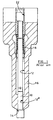
- the fuel injector of the present invention includes a nozzle body 26 which is provided with a through bore 28 within which a valve needle 30 is slidable.
- the bore 28 includes an enlarged diameter region 28 a , an intermediate region 28 b of reduced diameter and a lower region 28 c of further reduced diameter, the bore defining a step 28 d between the intermediate region 28 b and the lower region 28 c .
- a sleeve member 32 is received within the bore 28, the outer surface of the sleeve member 32 being of stepped form and defining a step 32 a which is engageable with the step 28 d defined by the bore 28.
- the valve needle 30 extends through the sleeve member 32, the valve needle 30 including an end region 30 a of enlarged diameter which projects through the lower open end of the through bore 28 and the sleeve member 32 and which is engageable with a seating 34 defined by the nozzle body 26.
- the valve needle 30 also includes a region of reduced diameter 30 b which defines, together with the inner surface of the sleeve member 32, a delivery chamber 48 for fuel.
- the sleeve member 32 is biased by means of a compression spring 36 and fuel pressure towards a position in which part of the lower surface 35 of the sleeve member 32 engages the enlarged end region 30 a of the valve needle 30 forming a seal at a seating 35 a , the compression spring 36 being housed within a spring chamber 38 defined by the intermediate region 28 b of the bore 28.
- the sleeve member 32 is provided with first and second sets of outlet openings 33, 37 respectively, one end of each outlet opening 33, 37 communicating with the delivery chamber 48 such that movement of the valve needle 30 away from the seating 34 permits fuel to flow from the delivery chamber 48 out through the first set of outlet openings 33, or through both sets of outlet openings 33, 37, depending on the extent of movement of the valve needle 30 away from the seating 34.
- the end of the compression spring 42 remote from the first abutment member 40 is in abutment with a second abutment member 46 which abuts or is connected to a guide member 47 associated with the valve needle 30, the guide member 47 serving to guide sliding movement of the valve needle 30 within the bore 28.
- the abutment member 40 is secured to the valve needle 30, the spring force due to the spring 42 acting on the abutment member 40 and thereby serving to bias the valve needle 30 into a position in which the enlarged end region 30 a of the valve needle 30 engages the seating 34 defined by the nozzle body 26.
- the compression spring 36 is pre-loaded with a lower load than the pre-load of the compression spring 42.
- fuel is supplied to the chamber 44 through a supply passage 46 provided in the end of the nozzle body 26 remote from the seating 34, the supply passage 46 communicating with a source of fuel at high pressure such as, for example, a common rail of a common rail fuel system, to permit fuel to be delivered to the chamber 44.
- Fuel within the chamber 44 is able to flow to the spring chamber 38 via flats, slots or grooves machined on the surface of the valve needle 30.
- Fuel delivered to the spring chamber 38 is able to flow to the delivery chamber 48 by means of a narrow clearance passage 50 which is defined between the inner surface of the sleeve member 32 and flats, slots or grooves provided on the surface of the valve needle 30.
- valve needle 30 exposed to fuel pressure within the bore 28 are chosen to ensure that, in use, with fuel under high pressure delivered to the bore 28, the valve needle 30 is urged against the seating 34 by the fuel pressure and the spring 42 to prevent fuel delivery into the engine cylinder or other combustion space.
- valve needle 30 In use, movement of the valve needle 30 away from the seating 34 is controlled in a conventional way, for example by means of a piezoelectric actuator arrangement (not shown).
- a surface associated with the valve needle 30 may be exposed to fuel pressure within a control chamber, fuel pressure within the control chamber being controlled by varying the energisation level, and hence the axial length, of a piezoelectric stack.
- valve needle movement may be controlled directly by varying the axial length of the piezoelectric stack.
- movement of the valve needle 30 may be controlled in a conventional way by means of an electromagnetic actuator arrangement.
- the piezoelectric actuator is energised such that fuel pressure within the control chamber acting on a surface associated with the valve needle 30 provides a downwards force on the valve needle 30 which is sufficient to overcome the force due to fuel pressure within the bore 28.
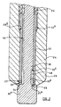
- the valve needle 30 is moved outwardly, the enlarged end region 30 a moving away from the seating 34 to expose the first set of outlet openings 33, as shown in Figure 4, the force due to the spring 36 and fuel pressure maintaining the seal at the seating 35 a .
- fuel within the delivery chamber 48 is able to flow out through the first set of outlet openings 33 into the engine cylinder.
- fuel pressure within the delivery chamber 48 acts on the sleeve member 32 in a radially outward direction, thereby serving to dilate the sleeve member 32 and improve the seal between the sleeve member 32 and the bore region 28 a , fuel within the spring chamber 38 therefore being unable to escape from the fuel injector between the nozzle body 26 and the sleeve member 32.
- the piezoelectric actuator arrangement is deenergised from the first energisation level, causing fuel pressure within the control chamber acting on the surface associated with the valve needle 30 to be reduced.
- the valve needle 30 therefore moves inwardly due to fuel pressure within the bore 28 until the enlarged end region 30 a of the valve needle 30 engages the seating 34 defined by the nozzle body 26. Fuel is therefore unable to flow out through the first set of outlet openings 33 and fuel injection ceases.
- the piezoelectric actuator may be energised to a second, higher energisation level causing fuel pressure within the control chamber acting on the surface associated with the valve needle 30 to be further increased, the valve needle 30 thereby moving outwardly away from the seating 34 into a second fuel injecting position, as shown in Figure 5, with both the first and second outlet openings 33, 37 exposed such that fuel within the delivery chamber 48 is delivered through both the first and second sets of outlet openings 33, 37.
- the extent of outward movement of the valve needle 30 away from the seating 34 is limited by engagement between the stepped surface 32 a provided on the sleeve member 32 and the seating 28 d defined by the bore 28, the stepped surface 32 a provided on the sleeve member 32 engaging the seating 28 d so as to form a substantially fluid-tight seal such that fuel within the spring chamber 38 is unable to flow past the seating 28 d .
- the effect of the seal formed at the seating 28 d in addition to the effect of the dilation of the sleeve member 32, causes the seal between the nozzle body 26 and the sleeve member 32 to be further improved. Thus, during this stage of operation, fuel leakage between the nozzle body 26 and the sleeve member 32 is substantially eliminated.
- the piezoelectric actuator In order to cease fuel injection the piezoelectric actuator is de-energised, causing fuel pressure within the control chamber acting on the surface associated with the valve needle 30 to be reduced, thereby causing the valve needle 30 to move inwardly until the enlarged end region 30 a engages the seating 34, as shown in Figure 3, causing fuel injection through the first and second sets of outlet openings 33, 37 to be terminated.
- the piezoelectric actuator may be deenergised to the first energisation level, thereby causing the valve needle 30 to move inwardly to the position shown in Figure 4 in which only the first set of outlet openings 33 are exposed.
- the invention provides the advantage that, as the enlarged end region 30 a of the valve needle is sealingly engageable with a seating defined by both the sleeve member 32 and the nozzle body 26, the seating can be manufactured more easily. Additionally, as the sleeve member 32 is a separate component, the first and second sets of outlet openings 33, 37 can also be manufactured relatively easily, prior to assembly of the fuel injector. The first and second sets of outlet openings 33, 37 provided in the sleeve member 32 can also be positioned in close proximity to the end face of the sleeve member 32 and, thus, the valve needle 30 need only be moved by a relatively small amount away from the seating 34 in order to commence injection.
- the lower outlet opening 33 may be provided by forming a recess or groove in the lower surface 35 of the sleeve member 32.
- first and second sets of outlet openings 33, 37 having a different number of openings in each set, or having openings of different size, or having openings with a different fuel spray cone angle, it will be appreciated that by selectively injecting fuel from either the first set of outlet openings 33 alone, or from both the first and second sets of outlet openings 33, 37 together, by controlling the extent of movement of the valve needle 30 away from the seating 34, the fuel injection characteristics can be varied, in use.
- outlet openings may be provided in the sleeve member.
- a third or further set of outlet openings may be provided in the sleeve member, the actuator arrangement being arranged to control movement of the valve needle between first, second, third or further fuel injecting positions.
Landscapes
- Engineering & Computer Science (AREA)
- Chemical & Material Sciences (AREA)
- Combustion & Propulsion (AREA)
- Mechanical Engineering (AREA)
- General Engineering & Computer Science (AREA)
- Fuel-Injection Apparatus (AREA)
Applications Claiming Priority (2)
| Application Number | Priority Date | Filing Date | Title |
|---|---|---|---|
| GB9919424 | 1999-08-18 | ||
| GBGB9919424.3A GB9919424D0 (en) | 1999-08-18 | 1999-08-18 | Fuel injector |
Publications (2)
| Publication Number | Publication Date |
|---|---|
| EP1077326A2 true EP1077326A2 (fr) | 2001-02-21 |
| EP1077326A3 EP1077326A3 (fr) | 2003-01-22 |
Family
ID=10859295
Family Applications (1)
| Application Number | Title | Priority Date | Filing Date |
|---|---|---|---|
| EP00306751A Withdrawn EP1077326A3 (fr) | 1999-08-18 | 2000-08-08 | Injecteur à combustible |
Country Status (3)
| Country | Link |
|---|---|
| US (1) | US6340017B1 (fr) |
| EP (1) | EP1077326A3 (fr) |
| GB (1) | GB9919424D0 (fr) |
Families Citing this family (11)
| Publication number | Priority date | Publication date | Assignee | Title |
|---|---|---|---|---|
| GB9923823D0 (en) | 1999-10-09 | 1999-12-08 | Lucas Industries Ltd | Fuel injector |
| ES2280318T3 (es) | 2000-07-18 | 2007-09-16 | Delphi Technologies, Inc. | Inyector de combustible. |
| GB0107575D0 (en) * | 2001-03-27 | 2001-05-16 | Delphi Tech Inc | Control valve arrangement |
| US6626381B2 (en) * | 2001-11-08 | 2003-09-30 | Bombardier Motor Corporation Of America | Multi-port fuel injection nozzle and system and method incorporating same |
| US7210640B2 (en) * | 2001-11-30 | 2007-05-01 | Caterpillar Inc | Fuel injector spray alteration through a moveable tip sleeve |
| US20030102390A1 (en) * | 2001-11-30 | 2003-06-05 | Clarke John M. | Method and apparatus to control a moveable tip sleeve. |
| US7252249B2 (en) * | 2002-02-22 | 2007-08-07 | Delphi Technologies, Inc. | Solenoid-type fuel injector assembly having stabilized ferritic stainless steel components |
| DE10231583A1 (de) * | 2002-07-11 | 2004-01-29 | Daimlerchrysler Ag | Kraftstoffeinspritzdüse einer Brennkraftmaschine mit Direkteinspritzdüse |
| US6945475B2 (en) * | 2002-12-05 | 2005-09-20 | Caterpillar Inc | Dual mode fuel injection system and fuel injector for same |
| US7520269B2 (en) * | 2005-06-28 | 2009-04-21 | Advanced Global Equities And Intellectual Properties | Fuel injector nozzle assembly |
| WO2013122317A1 (fr) * | 2012-02-13 | 2013-08-22 | 현대중공업 주식회사 | Dispositif d'entraînement de clapet de non-retour pour injection de gaz |
Citations (4)
| Publication number | Priority date | Publication date | Assignee | Title |
|---|---|---|---|---|
| FR2654469A1 (fr) * | 1989-11-14 | 1991-05-17 | Bosch Gmbh Robert | Injecteur de carburant pour moteur a combustion interne, permettant un jet de carburant en forme de parapluie. |
| EP0872636A2 (fr) * | 1997-04-18 | 1998-10-21 | Robert Bosch Gmbh | Soupape d'injection de combustible pour moteurs à combustion interne |
| EP0967386A2 (fr) * | 1998-05-29 | 1999-12-29 | LUCAS INDUSTRIES public limited company | Injecteur de combustible |
| EP1116878A2 (fr) * | 2000-01-15 | 2001-07-18 | Delphi Technologies, Inc. | Injecteur de combustible |
Family Cites Families (7)
| Publication number | Priority date | Publication date | Assignee | Title |
|---|---|---|---|---|
| US5522550A (en) * | 1992-06-10 | 1996-06-04 | Robert Bosch Gmbh | Injection nozzle for internal combustion engines |
| DE4440369A1 (de) * | 1994-11-11 | 1996-05-15 | Bosch Gmbh Robert | Kraftstoffeinspritzventil für Brennkraftmaschinen |
| DE19633260A1 (de) * | 1996-08-17 | 1998-02-19 | Bosch Gmbh Robert | Einspritzventil, insbesondere zum direkten Einspritzen von Kraftstoff in einen Brennraum eines Verbrennungsmotors |
| DE19753162A1 (de) * | 1997-11-29 | 1999-06-02 | Bosch Gmbh Robert | Kraftstoffeinspritzventil für Brennkraftmaschinen |
| DE19900037A1 (de) * | 1999-01-02 | 2000-07-06 | Bosch Gmbh Robert | Kraftstoffeinspritzventil |
| US6042028A (en) * | 1999-02-18 | 2000-03-28 | General Motors Corporation | Direct injection fuel injector spray nozzle and method |
| US6270024B1 (en) * | 2000-01-12 | 2001-08-07 | Woodward Governor Company | Hydraulically actuated fuel injector cartridge and system for high pressure gaseous fuel injection |
-
1999
- 1999-08-18 GB GBGB9919424.3A patent/GB9919424D0/en not_active Ceased
-
2000
- 2000-08-08 EP EP00306751A patent/EP1077326A3/fr not_active Withdrawn
- 2000-08-11 US US09/637,944 patent/US6340017B1/en not_active Expired - Fee Related
Patent Citations (4)
| Publication number | Priority date | Publication date | Assignee | Title |
|---|---|---|---|---|
| FR2654469A1 (fr) * | 1989-11-14 | 1991-05-17 | Bosch Gmbh Robert | Injecteur de carburant pour moteur a combustion interne, permettant un jet de carburant en forme de parapluie. |
| EP0872636A2 (fr) * | 1997-04-18 | 1998-10-21 | Robert Bosch Gmbh | Soupape d'injection de combustible pour moteurs à combustion interne |
| EP0967386A2 (fr) * | 1998-05-29 | 1999-12-29 | LUCAS INDUSTRIES public limited company | Injecteur de combustible |
| EP1116878A2 (fr) * | 2000-01-15 | 2001-07-18 | Delphi Technologies, Inc. | Injecteur de combustible |
Also Published As
| Publication number | Publication date |
|---|---|
| GB9919424D0 (en) | 1999-10-20 |
| EP1077326A3 (fr) | 2003-01-22 |
| US6340017B1 (en) | 2002-01-22 |
Similar Documents
| Publication | Publication Date | Title |
|---|---|---|
| US6220528B1 (en) | Fuel injector including an outer valve needle, and inner valve needle slidable within a bore formed in the outer valve needle | |
| US6024297A (en) | Fuel injector | |
| US6422199B1 (en) | Fuel injector | |
| US6467702B1 (en) | Fuel injector | |
| US6378503B1 (en) | Fuel injector | |
| US6340121B1 (en) | Fuel injector | |
| US6776354B2 (en) | Fuel injector | |
| US7971802B2 (en) | Fuel injector | |
| US6513733B1 (en) | Fuel injection and method of assembling a fuel injector | |
| US6616070B1 (en) | Fuel injector | |
| US6224001B1 (en) | Fuel injector | |
| US6612508B2 (en) | Fuel injector | |
| JPH06229347A (ja) | 電磁燃料噴射弁 | |
| JP2965042B2 (ja) | ディーゼル機関用電磁燃料噴射装置 | |
| US6340017B1 (en) | Fuel injector | |
| US7523875B2 (en) | Injection nozzle | |
| US6889918B2 (en) | Fuel injector | |
| US6425368B1 (en) | Fuel injector | |
| EP0844383B1 (fr) | Injecteur | |
| EP0921302A2 (fr) | Injecteur de combustible | |
| GB2336628A (en) | A fuel injector, for an I.C. engine, having a three way two position needle control valve | |
| US6321999B1 (en) | Fuel injector | |
| JPH07293387A (ja) | 電磁燃料噴射弁 | |
| EP1236883A2 (fr) | Système de combustible | |
| GB2345741A (en) | Pressure balanced control valve |
Legal Events
| Date | Code | Title | Description |
|---|---|---|---|
| PUAI | Public reference made under article 153(3) epc to a published international application that has entered the european phase |
Free format text: ORIGINAL CODE: 0009012 |
|
| AK | Designated contracting states |
Kind code of ref document: A2 Designated state(s): AT BE CH CY DE DK ES FI FR GB GR IE IT LI LU MC NL PT SE |
|
| AX | Request for extension of the european patent |
Free format text: AL;LT;LV;MK;RO;SI |
|
| PUAL | Search report despatched |
Free format text: ORIGINAL CODE: 0009013 |
|
| AK | Designated contracting states |
Kind code of ref document: A3 Designated state(s): AT BE CH CY DE DK ES FI FR GB GR IE IT LI LU MC NL PT SE |
|
| AX | Request for extension of the european patent |
Free format text: AL;LT;LV;MK;RO;SI |
|
| RIC1 | Information provided on ipc code assigned before grant |
Free format text: 7F 02M 61/08 A, 7F 02M 61/18 B, 7F 02M 51/06 B, 7F 02M 61/06 B |
|
| 17P | Request for examination filed |
Effective date: 20030408 |
|
| 17Q | First examination report despatched |
Effective date: 20030613 |
|
| AKX | Designation fees paid |
Designated state(s): DE ES FR GB IT |
|
| STAA | Information on the status of an ep patent application or granted ep patent |
Free format text: STATUS: THE APPLICATION IS DEEMED TO BE WITHDRAWN |
|
| 18D | Application deemed to be withdrawn |
Effective date: 20031224 |