EP1077325A2 - One piece piston with supporting piston skirt - Google Patents
One piece piston with supporting piston skirt Download PDFInfo
- Publication number
- EP1077325A2 EP1077325A2 EP00116002A EP00116002A EP1077325A2 EP 1077325 A2 EP1077325 A2 EP 1077325A2 EP 00116002 A EP00116002 A EP 00116002A EP 00116002 A EP00116002 A EP 00116002A EP 1077325 A2 EP1077325 A2 EP 1077325A2
- Authority
- EP
- European Patent Office
- Prior art keywords
- piston
- skirt
- piece
- flange portion
- pin
- Prior art date
- Legal status (The legal status is an assumption and is not a legal conclusion. Google has not performed a legal analysis and makes no representation as to the accuracy of the status listed.)
- Granted
Links
- 238000001816 cooling Methods 0.000 claims abstract description 57
- 238000002485 combustion reaction Methods 0.000 claims abstract description 30
- 239000012809 cooling fluid Substances 0.000 claims description 14
- 238000003466 welding Methods 0.000 claims description 12
- 229910000831 Steel Inorganic materials 0.000 claims description 4
- 239000000463 material Substances 0.000 claims description 4
- 239000010959 steel Substances 0.000 claims description 4
- 239000000446 fuel Substances 0.000 description 5
- 230000006835 compression Effects 0.000 description 3
- 238000007906 compression Methods 0.000 description 3
- 239000012530 fluid Substances 0.000 description 3
- 238000004519 manufacturing process Methods 0.000 description 3
- 238000000034 method Methods 0.000 description 3
- KGSSUTVUTPLSQW-UHFFFAOYSA-N Robustone Chemical compound C1=C2OCOC2=CC(C2=COC=3C=C4OC(C=CC4=C(O)C=3C2=O)(C)C)=C1 KGSSUTVUTPLSQW-UHFFFAOYSA-N 0.000 description 2
- 238000005242 forging Methods 0.000 description 2
- 230000002028 premature Effects 0.000 description 2
- 210000000707 wrist Anatomy 0.000 description 2
- 238000010276 construction Methods 0.000 description 1
- 238000005336 cracking Methods 0.000 description 1
- 230000003247 decreasing effect Effects 0.000 description 1
- 238000010894 electron beam technology Methods 0.000 description 1
- 239000007789 gas Substances 0.000 description 1
- 238000002347 injection Methods 0.000 description 1
- 239000007924 injection Substances 0.000 description 1
- 238000003754 machining Methods 0.000 description 1
- 239000000203 mixture Substances 0.000 description 1
Images


Classifications
-
- F—MECHANICAL ENGINEERING; LIGHTING; HEATING; WEAPONS; BLASTING
- F02—COMBUSTION ENGINES; HOT-GAS OR COMBUSTION-PRODUCT ENGINE PLANTS
- F02F—CYLINDERS, PISTONS OR CASINGS, FOR COMBUSTION ENGINES; ARRANGEMENTS OF SEALINGS IN COMBUSTION ENGINES
- F02F3/00—Pistons
- F02F3/16—Pistons having cooling means
- F02F3/20—Pistons having cooling means the means being a fluid flowing through or along piston
- F02F3/22—Pistons having cooling means the means being a fluid flowing through or along piston the fluid being liquid
-
- F—MECHANICAL ENGINEERING; LIGHTING; HEATING; WEAPONS; BLASTING
- F02—COMBUSTION ENGINES; HOT-GAS OR COMBUSTION-PRODUCT ENGINE PLANTS
- F02F—CYLINDERS, PISTONS OR CASINGS, FOR COMBUSTION ENGINES; ARRANGEMENTS OF SEALINGS IN COMBUSTION ENGINES
- F02F3/00—Pistons
- F02F3/0015—Multi-part pistons
- F02F3/003—Multi-part pistons the parts being connected by casting, brazing, welding or clamping
-
- F—MECHANICAL ENGINEERING; LIGHTING; HEATING; WEAPONS; BLASTING
- F02—COMBUSTION ENGINES; HOT-GAS OR COMBUSTION-PRODUCT ENGINE PLANTS
- F02F—CYLINDERS, PISTONS OR CASINGS, FOR COMBUSTION ENGINES; ARRANGEMENTS OF SEALINGS IN COMBUSTION ENGINES
- F02F3/00—Pistons
- F02F3/0015—Multi-part pistons
- F02F3/003—Multi-part pistons the parts being connected by casting, brazing, welding or clamping
- F02F2003/0061—Multi-part pistons the parts being connected by casting, brazing, welding or clamping by welding
-
- F—MECHANICAL ENGINEERING; LIGHTING; HEATING; WEAPONS; BLASTING
- F02—COMBUSTION ENGINES; HOT-GAS OR COMBUSTION-PRODUCT ENGINE PLANTS
- F02F—CYLINDERS, PISTONS OR CASINGS, FOR COMBUSTION ENGINES; ARRANGEMENTS OF SEALINGS IN COMBUSTION ENGINES
- F02F2200/00—Manufacturing
- F02F2200/04—Forging of engine parts
-
- F—MECHANICAL ENGINEERING; LIGHTING; HEATING; WEAPONS; BLASTING
- F05—INDEXING SCHEMES RELATING TO ENGINES OR PUMPS IN VARIOUS SUBCLASSES OF CLASSES F01-F04
- F05C—INDEXING SCHEME RELATING TO MATERIALS, MATERIAL PROPERTIES OR MATERIAL CHARACTERISTICS FOR MACHINES, ENGINES OR PUMPS OTHER THAN NON-POSITIVE-DISPLACEMENT MACHINES OR ENGINES
- F05C2201/00—Metals
- F05C2201/04—Heavy metals
- F05C2201/0433—Iron group; Ferrous alloys, e.g. steel
- F05C2201/0448—Steel
Definitions
- This invention relates generally to a piston for an internal combustion engine and more particularly to a one piece piston having a supporting piston skirt.
- the present invention is directed to overcoming one or more of the problems set forth above.
- a one piece piston has a piston body with a top surface and a longitudinal axis.
- a support portion extends in a direction longitudinally from the piston body.
- a first pin boss and a second pin boss is connected to the support portion.
- the first and second pin bosses are spaced apart and each have a pin bore.
- Each of the pin bores have a bore axis and are axially aligned with each other.
- the bore axes are oriented transverse to the longitudinal axis.
- a flange portion is connected to the piston body at a preselected location between the top surface and the pin bore.
- the flange portion extends radially from the piston body.
- a piston skirt has first and second skirt portions. The first and second skirt portions are each connected to said flange portion and said support portion. The piston skirt supports the flange portion on the support portion.
- a one piece piston for an internal combustion engine having a cylinder and a cylinder bore is provided.
- the one piece piston is disposed in the cylinder bore and is adapted to reciprocally move in the cylinder bore.
- the one piece piston includes a piston body having a top surface, a longitudinal axis, and a support portion extending in a direction longitudinally from the piston body.
- a first pin boss and a second pin boss are connected to the support portion.
- the first and second pin bosses are spaced apart.
- Each of the pin bosses having a pin bore.
- Each of the pin bores have a bore axis and are axially aligned with each other.
- the bore axes are oriented transverse to the longitudinal axis.
- a flange portion is connected to the piston body at a preselected location between the top surface and the pin bore.
- the flange portion extends radially from the piston body.
- a piston skirt has first and second skirt portions.
- the first and second skirt portions each are connected to the flange portion and the support portion.
- the first skirt portion is spaced from and opposite the second skirt portion.
- the first and second skirt portions extend from the flange portion in a substantially axial direction relative to the longitudinal axis.
- the first and second skirt portions each have first and second spaced end portions.
- the first and second skirt portions each extending between the first and second pin bosses and are each connected at the first end portion to the first pin boss and at the second end portion to the second pin boss.
- the piston body, the support portion, the flange portion, and the piston skirt are forged in one piece from a steel material.
- a ring belt portion is disposed about the piston body. The ring belt portion is connected to the piston body and to the flange portion by welding.
- a piston cooling gallery is disposed annularly in the piston body. The piston cooling gallery is closed by the flange and ring belt portions to define a closed piston cooling gallery.
- the engine 10 has an engine block 12, at least one cylinder 14 having a cylinder bore 16 in the engine block 12, at least one cylinder head 18 mounted on the engine block 12 in a conventional manner, and a one piece piston 20 disposed in the cylinder bore 16 and reciprocally movable in the cylinder bore 16 between bottom and top dead center positions.
- the one piece piston 20, cylinder head 18, and cylinder bore 16 define a combustion chamber 22 therein.
- At least one intake valve 24 and one exhaust valve 26 are disposed in the cylinder head 18 and movable between open and closed positions relative to valve seats 28 disposed in the cylinder head 18 to pass gasses to and from the combustion chamber 22 in a conventional manner.
- a connecting rod (not shown) is pivotally connected to the one piece piston 20 in a conventional manner, such as, by a wrist pin 30 (Figs. 2-4).
- a fuel system of any suitable and conventional design, for example, a fuel injection system having a fuel injector 32, communicates fuel to the combustion chamber 22.
- the one piece piston 20 is constructed in a manner to provide increased strength, light weight and improved cooling capabilities over other piston designs.
- the one piece piston 20 has a piston body 34 and a longitudinal axis 36.
- the piston body 34 has a head portion 38 and a top surface 40.
- a one piece piston is different in construction than an articulated piston, sometimes referred to as a two piece piston.
- An articulated piston has, in addition to other differences, a piston skirt that is pivotally connected to the wrist pin and free from connection to the piston body. This invention is not suited for use with articulated pistons.
- a support portion 42 of the one piece piston 20 extends in a direction longitudinally from the head portion 38.
- a first pin boss 44 and a second pin boss 45 connected to the support portion.
- the first and second pin bosses 44,45 are spaced apart and each have a pin bore 46.
- the pin bores 44,45 each have a pin bore axis 48 and are axially aligned with each other.
- the pin bore axes 48 are oriented transverse the longitudinal axis 36 of the one piece piston 20.
- a flange portion 50 is connected to the head portion 38 of the piston body 34 at a preselected location between the top surface 40 and the pin bore 46 and extends in a direction radially from and about the piston body 34.
- a piston ring belt portion 52 is disposed about the piston body 34.
- the piston ring belt portion 52 is connected to the head portion 38 and to the flange portion 50 of the piston body 34 by welding, for example, laser, electron beam or any other suitable welding process.
- the piston ring belt portion 52 has first and second spaced apart ends 54,56 and an inside surface 58.
- the inside surface 58 is welded to the head portion 38 of the piston body 34 and the second end 56 is welded to the flange portion 50 of the piston body 34.
- the strength of the one piece piston 20 is increased by supporting the piston ring belt portion 52 with the a flange portion 50.
- the flange portion 50 has a ring end portion 60.
- the ring end portion 60 defines a first side 62 of a first piston ring groove 64 of a plurality of piston ring grooves 66.
- the piston ring belt portion 52 defines a second side 68 of the first piston ring groove 64.
- the first and second sides 62,68 are spaced a preselected distance apart.
- the welding connecting the flange portion 50 to the second end of the piston ring belt portion 52 is preferably at a location between the first and second sides 62,68 of the first piston ring groove 64.
- a piston cooling gallery 70 is disposed annularly in the head portion 38 of the piston body 34.
- the piston cooling gallery 70 is closed by the flange portion 50 and piston ring belt portion 52 to define a closed piston cooling gallery 72 with the piston body 34 of the one piece piston 20.
- the closed piston cooling gallery 72 has first and second spaced apart extreme end surface locations 74,76 defining a preselected longitudinal gallery length "L".
- the length "L” being of a magnitude sufficient to enable a substantial and adequate amount of space for the shaking of a cooling fluid contained within the closed piston cooling gallery 72 and thereby facilitate cooling of the piston ring belt portion 52 and piston body 34.
- the length "L” of the closed piston cooling gallery 72 is a function of a diameter "D" of the piston and within a range between 20 and 30 percent of the magnitude of the diameter "D.
- the closed piston cooling gallery 72 has a pair of first spaced apart side surface locations 78 defining a first preselected gallery width "W1".
- the closed piston cooling gallery width "W1" is smaller in magnitude than the closed piston cooling gallery length "L”.
- the closed piston cooling gallery 72 also has a pair of second spaced apart side surface locations 80 which are spaced from said pair of first spaced apart side surface locations 72 and which define a second preselected closed piston cooling gallery width "W2".
- the second closed piston cooling gallery width "W2" is smaller in magnitude than the first piston cooling gallery width "W1".
- the predetermined proportion between "W1", "W2” and “L” is based on fluid dynamics.
- top surface 40 and the first end 54 is located closer to the pair of second spaced apart side surface locations 80 than to the first pair of spaced apart side surface locations 78. This predetermined proportion and relationship provides adequate fluid shaking within the closed piston cooling gallery 72 and optimizes cooling of the one piece piston 20.
- the one piece piston has a plurality of spaced apart cooling fluid passing passageways 82 disposed radially in the head portion 38 of the piston body 34.
- the cooling fluid passing passageways 82 open into the piston cooling gallery 70 and into a recess 84 located centrally in the head portion 38 of the piston body 34.
- the cooling fluid passing passageways 82 provide for the passing of cooling fluid between the closed piston cooling gallery 72 and the recess 84.
- the cooling fluid passing passageways 82 are preferably machined radially inwardly into the piston body 34 prior to welding of the piston ring belt portion 52 to the piston body 34.
- the plurality of spaced apart piston ring grooves 66 are disposed in the piston ring belt portion.
- the piston ring grooves 66 are radially spaced from the longitudinal axis 36 and axially spaced relative to the longitudinal axis 36 between the first and second extreme end surface locations 74,76 of the closed piston cooling gallery 72. It is to be noted that the size, proportions and location of the closed piston cooling gallery 72, as heretofore described, provides improved effective piston cooling capabilities allowing for operation in applications having higher internal combustion engine 10 pressures, temperatures and piston speed.
- a piston skirt 86 has first and second skirt portions 88,90.
- the first skirt portion 88 is spaced from and opposite the second skirt portion 90.
- the first and second skirt portions 88,90 are each connected to the flange portion 50 and the support portion 42.
- the piston skirt 86 extends from the flange portion in a substantially axial direction relative to the longitudinal axis 36 to a location past the pin bore axis 48.
- the piston skirt 86 being connected to the flange portion provides support to the flange portion and resists deflection thereof.
- the first and second skirt portions 88,90 each have first and second spaced end portions 92,94. Each of the first and second skirt portions 88,90 extend between the first and second pin bosses 44,45 and are connected at the first end portion 92 to the first pin boss 44 and at the second end portion 94 to the second pin boss 45.
- the piston skirt 86 being connected to the piston ring belt portion 52, and as described, provides for additional stiffness and reduces the potential for undesirable deflection of the piston skirt 86 and the piston ring belt portion 52.
- the first and second skirt portions 88,90 each have an outer surface 96 defined by a radius "R" generated about the longitudinal axis 36.
- the curved shape provides additional piston skirt 86 strength and also conforms to provide clearance between the piston skirt 86 and the cylinder bore 16.
- the head portion 38, the support portion 42 and the flange portion 50 of the piston body 34, and the piston skirt 86 are forged in one piece from any suitable steel material capable of withstanding the high combustion pressure, high piston speed, high temperatures and increased mechanical stress.
- a method of producing the one piece piston 20 includes the step of forging a unitary one piece piston body 34.
- the head portion 38, the flange portion 50, and the support portion 42 are forged to provide a one piece piston body 34.
- the cooling gallery 70 is provided annularly about the head portion 38 of the piston body 34 by forging, machining or any other suitable manufacturing process.
- the piston ring belt portion 52 is positioned about the piston body 34 and is connected to the piston body 34 by welding to close off the piston cooling gallery 70 and form the closed piston cooling gallery 72.
- the plurality of spaced apart cooling fluid passing passageways 82 are machined radially inwardly in the piston body 34 from an outward location and in a direction toward the longitudinal axis 36.
- the inside surface 58 of the piston ring belt portion 52 is welded to the piston body 34 and the second end 56 of the piston ring belt portion 52 is welded to the flange portion 50.
- the plurality of axially spaced apart piston ring grooves 66 are machined in the piston ring belt portion 52 subsequent to the welding of the piston ring belt portion 52 to the piston body 34.
- the piston skirt 86 is preferably formed at the same time the piston body 34 is being forged.
- the one piece piston 20 of the instant invention is manufactured by the method as set forth above to provide a light weight, high strength, cooled piston that is suitable for use in a high combustion pressure, high piston speed, high temperature and high mechanical stress environment.
- the one piece piston 20 as constructed enables the combustion pressures in the combustion chamber to be increased and thereby supports a maximization of the power output of the internal combustion engine for a given engine size.
- the operation of the one piece piston 20 in the internal combustion engine 10 can best be seen in Fig. 1.
- combustion of an air/fuel mixture in the combustion chamber 22 by auto ignition, spark ignition or a combination thereof causes the gases to expand and to force movement of the one piece piston downward and away from the cylinder head 18 within the cylinder bore 16.
- This linear movement is transformed by way of the connecting rod and the crankshaft into rotary crankshaft motion, the output of which is used to provide mechanical energy to power, for example, a stationary machine, an electrical generator, a mobile machine and a ship.
- the intake and exhaust valves 24,26 are opened and closed at suitable times during an engine cycle to pass intake air and exhaust gasses relative to the combustion chamber 22. Such operation is well known by those skilled in the art and will not be discussed in any greater detail.
- the closed piston cooling gallery 72 receives directed cooling fluid from within the engine sump (not shown).
- the cooling fluid within the closed piston cooling gallery 72 is shaken by the dynamics of movement of the one piece piston 20. This shaking, which is enhanced by the shape and proportions of the closed piston cooling gallery , causes the fluid within the closed piston cooling gallery to agitate and contact the internal surface 73 of the closed piston cooling gallery 72 and remove heat at the surface 72.
- the location of the closed piston cooling gallery 72 relative to the piston top surface 40 and the piston ring belt portion 52 maximizes heat transfer from these critical locations and enables the one piece piston 20 to perform satisfactorily at the required higher operating temperatures.
- the cooling fluid passing passageways 82 allow cooling fluid to exit the closed piston cooling gallery 72 and be replenished by replacement cooling fluid entering the closed piston cooling gallery 72 at another location. This further facilitates heat transfer and piston life.
- the strength of the one piece piston 20 is enhanced by the support provided to the piston ring belt portion 52 by the flange portion 50.
- the flange portion 50 being connected as described above to the piston ring belt portion 52, supports the second end 56 of the piston ring belt portion 52 and the reduces the potential for deflection of the piston ring belt portion 52 during operation of the internal combustion engine 10. As a result, the high forces acting on the piston ring belt portion 52 operation of the internal combustion engine 10 will be resisted and stress related premature failures will be prevented.
- the strength of the one piece piston 20 is also enhanced by the piston skirt 86.
- the piston skirt 86 is closed, absent a gap between the piston body 34 and the skirt 86, and connected, as discussed above, to the flange portion 42 and to the support portion 42. This further increases the rigidity of the piston skirt 86, the flange portion 50, and the piston ring belt portion 52. As a result, the forces exhibited during operation of the internal combustion engine 10 are resisted and deflection, cracking and the like of the piston skirt 86, the flange portion 50, and the piston ring belt portion 52 are prevented.
- the piston body 34 being forged as a unitary structure and the piston ring belt portion 52 being welded to the piston body 34 to complete the one piece piston 20 results in a robust one piece piston 20 capable of withstanding the forces applied during combustion cycles of the internal combustion engine 10.
Landscapes
- Engineering & Computer Science (AREA)
- Chemical & Material Sciences (AREA)
- Combustion & Propulsion (AREA)
- Mechanical Engineering (AREA)
- General Engineering & Computer Science (AREA)
- Physics & Mathematics (AREA)
- Fluid Mechanics (AREA)
- Pistons, Piston Rings, And Cylinders (AREA)
Abstract
Description
- This invention relates generally to a piston for an internal combustion engine and more particularly to a one piece piston having a supporting piston skirt.
- An efficient, light weight, compact, increased horsepower internal combustion engine is sought after by those involved in the industry. To achieve this it is necessary to push the engine design toward its mechanical limits. Increasing combustion pressures in the combustion chamber requires higher combustion temperatures, faster piston speeds and increased mechanical forces. As a result, the piston and associated components are placed under greater stress.
- In order to perform satisfactorily and live in such an environment it is necessary to provide a piston that has improved cooling capabilities, increased strength, and a short compression height for reduced mass and light weight. It is also important that such a piston is easy to manufacture with a high level of quality.
- It is known to provide a piston with a closed piston cooling gallery. An example of this is shown in United States Patent 4,581,983, dated April 15, 1986, to Horst Moebus. The closed piston cooling gallery of Moebus is provided by welding a top portion of the piston to a bottom portion of the piston along a planar surface. The top and bottom portions of the piston each have a portion of the cooling gallery disposed therein. This piston has an excessively tall compression height making it heavy and unsuitable for high speed operation. This piston is also difficult to manufacture and does not have the strength to withstand the increased stresses of the higher combustion pressures. The closed piston cooling gallery as configured in Moebus does not provide a height sufficient to permit adequate shaking of the cooling fluid within the closed piston cooling gallery. Therefore, the efficiency of cooling of the piston is inadequate.
- It is also known to provide a piston with decreased mass by reducing height. An example of this is shown in United States Patent 4,727,795, dated March 1, 1988, to Edward J. Murray. The short piston height is achieved by intersecting the ring band with the pin bores. This ring band intersection is unacceptable in a high piston speed engine, as leakage and wear in the region of the ring band would be excessive. Additionally, such a piston would not survive the high piston speeds because of insufficient cooling of the piston top portion. Further, the piston skirt, when welded to the piston top, does not permit removal of a pin in the pin bore and therefore makes assembly difficult and would not be a suitable choice. Additionally, providing a piston skirt that is removably attached to the piston reduces strength and further restrict the possibility of use in the proposed high speed, high temperature and high combustion pressure environment.
- United States Patent 5,78,846, dated July 14, 1998, to Siegfried Mielke discloses a forged or cast piston head of an articulated (two piece) piston. The ring band of the piston is welded to a top portion of the piston. Because this piston does not have a closed cooling gallery or a supported ring band it would not be suitable for use in a high piston speed, high temperature and high compression pressure environment. The higher forces applied to the piston would cause the unsupported ring band to deflect. This would result in unacceptable blowby leakage and premature stress failure of the piston. Further, the piston cooling would be inadequate and would result in a thermal related structural failure of the piston.
- The present invention is directed to overcoming one or more of the problems set forth above.
- In one aspect of the present invention, a one piece piston has a piston body with a top surface and a longitudinal axis. A support portion extends in a direction longitudinally from the piston body. A first pin boss and a second pin boss is connected to the support portion. The first and second pin bosses are spaced apart and each have a pin bore. Each of the pin bores have a bore axis and are axially aligned with each other. The bore axes are oriented transverse to the longitudinal axis. A flange portion is connected to the piston body at a preselected location between the top surface and the pin bore. The flange portion extends radially from the piston body. A piston skirt has first and second skirt portions. The first and second skirt portions are each connected to said flange portion and said support portion. The piston skirt supports the flange portion on the support portion.
- In another aspect of the present invention, a one piece piston for an internal combustion engine having a cylinder and a cylinder bore is provided. The one piece piston is disposed in the cylinder bore and is adapted to reciprocally move in the cylinder bore. The one piece piston includes a piston body having a top surface, a longitudinal axis, and a support portion extending in a direction longitudinally from the piston body. A first pin boss and a second pin boss are connected to the support portion. The first and second pin bosses are spaced apart. Each of the pin bosses having a pin bore. Each of the pin bores have a bore axis and are axially aligned with each other. The bore axes are oriented transverse to the longitudinal axis. A flange portion is connected to the piston body at a preselected location between the top surface and the pin bore. The flange portion extends radially from the piston body. A piston skirt has first and second skirt portions. The first and second skirt portions each are connected to the flange portion and the support portion. The first skirt portion is spaced from and opposite the second skirt portion. The first and second skirt portions extend from the flange portion in a substantially axial direction relative to the longitudinal axis. The first and second skirt portions each have first and second spaced end portions. The first and second skirt portions each extending between the first and second pin bosses and are each connected at the first end portion to the first pin boss and at the second end portion to the second pin boss. The piston body, the support portion, the flange portion, and the piston skirt are forged in one piece from a steel material. A ring belt portion is disposed about the piston body. The ring belt portion is connected to the piston body and to the flange portion by welding. A piston cooling gallery is disposed annularly in the piston body. The piston cooling gallery is closed by the flange and ring belt portions to define a closed piston cooling gallery.
-
- Fig. 1 is a diagrammatic sectional view of a portion of an internal combustion engine and an embodiment of a one piece piston of the present invention;
- Fig. 2 is a diagrammatic enlarged sectional view of the one piece piston of Fig. 1;
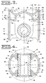
- Fig. 3 is a diagrammatic sectional view taken along lines 3-3 of Fig. 2; and
- Fig. 4 is a diagrammatic sectional view taken along lines 4-4 of Fig. 3.
-
- With reference to the drawings and particularly Fig. 1, a partial view of an
internal combustion engine 10 is shown. Theengine 10 has anengine block 12, at least onecylinder 14 having a cylinder bore 16 in theengine block 12, at least onecylinder head 18 mounted on theengine block 12 in a conventional manner, and a onepiece piston 20 disposed in the cylinder bore 16 and reciprocally movable in the cylinder bore 16 between bottom and top dead center positions. The onepiece piston 20,cylinder head 18, and cylinder bore 16 define a combustion chamber 22 therein. At least oneintake valve 24 and oneexhaust valve 26 are disposed in thecylinder head 18 and movable between open and closed positions relative tovalve seats 28 disposed in thecylinder head 18 to pass gasses to and from the combustion chamber 22 in a conventional manner. A connecting rod (not shown) is pivotally connected to the onepiece piston 20 in a conventional manner, such as, by a wrist pin 30 (Figs. 2-4). A fuel system, of any suitable and conventional design, for example, a fuel injection system having afuel injector 32, communicates fuel to the combustion chamber 22. - As best seen in Figs. 2-4, the one
piece piston 20 is constructed in a manner to provide increased strength, light weight and improved cooling capabilities over other piston designs. The onepiece piston 20 has apiston body 34 and alongitudinal axis 36. Thepiston body 34 has ahead portion 38 and atop surface 40. As known in the art, a one piece piston is different in construction than an articulated piston, sometimes referred to as a two piece piston. An articulated piston has, in addition to other differences, a piston skirt that is pivotally connected to the wrist pin and free from connection to the piston body. This invention is not suited for use with articulated pistons. - A
support portion 42 of the onepiece piston 20 extends in a direction longitudinally from thehead portion 38. Afirst pin boss 44 and asecond pin boss 45 connected to the support portion. The first andsecond pin bosses pin bore axis 48 and are axially aligned with each other. The pin bore axes 48 are oriented transverse thelongitudinal axis 36 of the onepiece piston 20. - A
flange portion 50 is connected to thehead portion 38 of thepiston body 34 at a preselected location between thetop surface 40 and the pin bore 46 and extends in a direction radially from and about thepiston body 34. - A piston
ring belt portion 52 is disposed about thepiston body 34. The pistonring belt portion 52 is connected to thehead portion 38 and to theflange portion 50 of thepiston body 34 by welding, for example, laser, electron beam or any other suitable welding process. In particular, the pistonring belt portion 52 has first and second spaced apart ends 54,56 and aninside surface 58. Theinside surface 58 is welded to thehead portion 38 of thepiston body 34 and thesecond end 56 is welded to theflange portion 50 of thepiston body 34. The strength of the onepiece piston 20 is increased by supporting the pistonring belt portion 52 with the aflange portion 50. - The
flange portion 50 has aring end portion 60. Thering end portion 60 defines afirst side 62 of a firstpiston ring groove 64 of a plurality ofpiston ring grooves 66. The pistonring belt portion 52 defines asecond side 68 of the firstpiston ring groove 64. The first andsecond sides flange portion 50 to the second end of the pistonring belt portion 52 is preferably at a location between the first andsecond sides piston ring groove 64. - A
piston cooling gallery 70 is disposed annularly in thehead portion 38 of thepiston body 34. Thepiston cooling gallery 70 is closed by theflange portion 50 and pistonring belt portion 52 to define a closedpiston cooling gallery 72 with thepiston body 34 of the onepiece piston 20. The closedpiston cooling gallery 72 has first and second spaced apart extremeend surface locations piston cooling gallery 72 and thereby facilitate cooling of the pistonring belt portion 52 andpiston body 34. The length "L" of the closedpiston cooling gallery 72 is a function of a diameter "D" of the piston and within a range between 20 and 30 percent of the magnitude of the diameter "D. - The closed
piston cooling gallery 72 has a pair of first spaced apartside surface locations 78 defining a first preselected gallery width "W1". The closed piston cooling gallery width "W1" is smaller in magnitude than the closed piston cooling gallery length "L". The closedpiston cooling gallery 72 also has a pair of second spaced apartside surface locations 80 which are spaced from said pair of first spaced apartside surface locations 72 and which define a second preselected closed piston cooling gallery width "W2". The second closed piston cooling gallery width "W2" is smaller in magnitude than the first piston cooling gallery width "W1". The predetermined proportion between "W1", "W2" and "L" is based on fluid dynamics. It is to be noted that, thetop surface 40 and thefirst end 54 is located closer to the pair of second spaced apartside surface locations 80 than to the first pair of spaced apartside surface locations 78. This predetermined proportion and relationship provides adequate fluid shaking within the closedpiston cooling gallery 72 and optimizes cooling of the onepiece piston 20. - The one piece piston has a plurality of spaced apart cooling fluid passing
passageways 82 disposed radially in thehead portion 38 of thepiston body 34. The cooling fluid passingpassageways 82 open into thepiston cooling gallery 70 and into arecess 84 located centrally in thehead portion 38 of thepiston body 34. The cooling fluid passingpassageways 82 provide for the passing of cooling fluid between the closedpiston cooling gallery 72 and therecess 84. The cooling fluid passingpassageways 82 are preferably machined radially inwardly into thepiston body 34 prior to welding of the pistonring belt portion 52 to thepiston body 34. - The plurality of spaced apart
piston ring grooves 66 are disposed in the piston ring belt portion. Thepiston ring grooves 66 are radially spaced from thelongitudinal axis 36 and axially spaced relative to thelongitudinal axis 36 between the first and second extremeend surface locations piston cooling gallery 72. It is to be noted that the size, proportions and location of the closedpiston cooling gallery 72, as heretofore described, provides improved effective piston cooling capabilities allowing for operation in applications having higherinternal combustion engine 10 pressures, temperatures and piston speed. - A
piston skirt 86 has first andsecond skirt portions first skirt portion 88 is spaced from and opposite thesecond skirt portion 90. The first andsecond skirt portions flange portion 50 and thesupport portion 42. Thepiston skirt 86 extends from the flange portion in a substantially axial direction relative to thelongitudinal axis 36 to a location past the pin boreaxis 48. Thepiston skirt 86 being connected to the flange portion provides support to the flange portion and resists deflection thereof. - The first and
second skirt portions end portions second skirt portions second pin bosses first end portion 92 to thefirst pin boss 44 and at thesecond end portion 94 to thesecond pin boss 45. Thepiston skirt 86 being connected to the pistonring belt portion 52, and as described, provides for additional stiffness and reduces the potential for undesirable deflection of thepiston skirt 86 and the pistonring belt portion 52. - The first and
second skirt portions outer surface 96 defined by a radius "R" generated about thelongitudinal axis 36. The curved shape providesadditional piston skirt 86 strength and also conforms to provide clearance between thepiston skirt 86 and the cylinder bore 16. - The
head portion 38, thesupport portion 42 and theflange portion 50 of thepiston body 34, and thepiston skirt 86 are forged in one piece from any suitable steel material capable of withstanding the high combustion pressure, high piston speed, high temperatures and increased mechanical stress. - A method of producing the one
piece piston 20 includes the step of forging a unitary onepiece piston body 34. In the instant step, thehead portion 38, theflange portion 50, and thesupport portion 42 are forged to provide a onepiece piston body 34. The coolinggallery 70 is provided annularly about thehead portion 38 of thepiston body 34 by forging, machining or any other suitable manufacturing process. The pistonring belt portion 52 is positioned about thepiston body 34 and is connected to thepiston body 34 by welding to close off thepiston cooling gallery 70 and form the closedpiston cooling gallery 72. - Prior to the welding of the piston
ring belt portion 52 to thepiston body 34, the plurality of spaced apart cooling fluid passingpassageways 82 are machined radially inwardly in thepiston body 34 from an outward location and in a direction toward thelongitudinal axis 36. - Preferably, the
inside surface 58 of the pistonring belt portion 52 is welded to thepiston body 34 and thesecond end 56 of the pistonring belt portion 52 is welded to theflange portion 50. The plurality of axially spaced apartpiston ring grooves 66 are machined in the pistonring belt portion 52 subsequent to the welding of the pistonring belt portion 52 to thepiston body 34. Thepiston skirt 86 is preferably formed at the same time thepiston body 34 is being forged. - With reference to the drawings, the one
piece piston 20 of the instant invention is manufactured by the method as set forth above to provide a light weight, high strength, cooled piston that is suitable for use in a high combustion pressure, high piston speed, high temperature and high mechanical stress environment. The onepiece piston 20 as constructed enables the combustion pressures in the combustion chamber to be increased and thereby supports a maximization of the power output of the internal combustion engine for a given engine size. - The operation of the one
piece piston 20 in theinternal combustion engine 10 can best be seen in Fig. 1. With the intake andexhaust valves cylinder head 18 within the cylinder bore 16. This linear movement is transformed by way of the connecting rod and the crankshaft into rotary crankshaft motion, the output of which is used to provide mechanical energy to power, for example, a stationary machine, an electrical generator, a mobile machine and a ship. The intake andexhaust valves - The closed
piston cooling gallery 72 receives directed cooling fluid from within the engine sump (not shown). The cooling fluid within the closedpiston cooling gallery 72 is shaken by the dynamics of movement of the onepiece piston 20. This shaking, which is enhanced by the shape and proportions of the closed piston cooling gallery , causes the fluid within the closed piston cooling gallery to agitate and contact theinternal surface 73 of the closedpiston cooling gallery 72 and remove heat at thesurface 72. The location of the closedpiston cooling gallery 72 relative to the pistontop surface 40 and the pistonring belt portion 52 maximizes heat transfer from these critical locations and enables the onepiece piston 20 to perform satisfactorily at the required higher operating temperatures. The cooling fluid passingpassageways 82 allow cooling fluid to exit the closedpiston cooling gallery 72 and be replenished by replacement cooling fluid entering the closedpiston cooling gallery 72 at another location. This further facilitates heat transfer and piston life. - The strength of the one
piece piston 20 is enhanced by the support provided to the pistonring belt portion 52 by theflange portion 50. Theflange portion 50, being connected as described above to the pistonring belt portion 52, supports thesecond end 56 of the pistonring belt portion 52 and the reduces the potential for deflection of the pistonring belt portion 52 during operation of theinternal combustion engine 10. As a result, the high forces acting on the pistonring belt portion 52 operation of theinternal combustion engine 10 will be resisted and stress related premature failures will be prevented. - The strength of the one
piece piston 20 is also enhanced by thepiston skirt 86. Thepiston skirt 86 is closed, absent a gap between thepiston body 34 and theskirt 86, and connected, as discussed above, to theflange portion 42 and to thesupport portion 42. This further increases the rigidity of thepiston skirt 86, theflange portion 50, and the pistonring belt portion 52. As a result, the forces exhibited during operation of theinternal combustion engine 10 are resisted and deflection, cracking and the like of thepiston skirt 86, theflange portion 50, and the pistonring belt portion 52 are prevented. - The
piston body 34 being forged as a unitary structure and the pistonring belt portion 52 being welded to thepiston body 34 to complete the onepiece piston 20 results in a robust onepiece piston 20 capable of withstanding the forces applied during combustion cycles of theinternal combustion engine 10. - Other aspects, objects and advantages of this invention can be obtained from a study of the drawings, the disclosure and the appended claims.
Claims (13)
- A one piece piston (20), comprising:a piston body (34) having a top surface (40) and a longitudinal axis (36);a support portion (42) extending in a direction longitudinally from said piston body (34);a first pin boss (44) and a second pin boss (45) being connected to said support portion (42), said first and second pin bosses (44,45) being spaced apart and each having a pin bore (46), each of said pin bores (46) having a bore axis (48) and being axially aligned with each other, said bore axes (48) being oriented transverse to said longitudinal axis (36);a flange portion (50) connected to said piston body (34) at a preselected location between the top surface (40) and the pin bore (46), said flange portion (50) extending radially from said piston body (34); anda piston skirt (86) having first and second skirt portions (88,90), said first and second skirt portions (88,90) each being connected to said flange portion (50) and said support portion (42), said piston skirt (86) supporting the flange portion (50) on the support portion (42).
- The one piece piston (20), as set forth in claim 1, wherein said first skirt portion (88) being spaced from and opposite the second skirt portion (90).
- The one piece piston (20), as set forth in claim 2, wherein said first and second skirt portions (88,90) extending from the flange portion (50) in a substantially axial direction relative to the longitudinal axis (36) to a location past the pin bore (46).
- The one piece piston (20), as set forth in claim 3, wherein said first and second skirt portions (88,90) each have first and second spaced end portions (92,94), said first and second skirt portions (88,90) each extending between the first and second pin bosses (44,45) and each being connected at the first end portion (92) to the first pin boss (44) and at the second end portion (94) to the second pin boss (45).
- The one piece piston (20), as set forth in claim 4, wherein said first and second skirt portions (88,90) each have an outer surface defined by a radius "R" generated about said longitudinal axis (36).
- The one piece piston (20), as set forth in claim 4, wherein said piston body (34), said support portion (42), said flange portion (50), and said piston skirt (86) being forged in one piece from a steel material.
- The one piece piston (20), as set forth in claim 6, including a ring belt portion (52) disposed about said piston body (34), said ring belt portion (52) being connected to said piston body (34) and to said flange portion (50) by welding.
- The one piece piston (20), as set forth in claim 7, including, a piston cooling gallery (70) disposed annularly in the piston body (34), said piston cooling gallery (70) being closed by said flange and ring belt portions (50,52) to define a closed piston cooling gallery (72) therein.
- The one piece piston (20), as set forth in claim 8, wherein said closed piston cooling gallery (72) having first and second spaced apart extreme end locations (74,76) defining a preselected longitudinal gallery length "L", said length "L" being of a magnitude sufficient to enable substantial shaking of a cooling fluid contained within the closed piston cooling gallery (72) and cooling of the ring belt (52).
- The one piece piston (20), as set forth in claim 8, wherein said piston ring belt portion (52) having a plurality of spaced apart piston ring grooves (66) disposed therein, said piston grooves (66) being spaced axially relative to the longitudinal axis (36) between the first and second extreme end locations (74,76) of the closed piston cooling gallery (72).
- The one piece piston (20), as set forth in claim 8, wherein said piston ring belt portion (52) having first and second ends (92,94) and an inside surface (58), said inside surface (58) being welded to the piston body (34) and said second end (94) being welded to the flange portion (50).
- The one piece piston (20), as set forth in claim 11, wherein said flange portion (50) having a ring end portion (60), said ring end portion (60) including a first side (62) of a first piston ring groove (64) of said plurality of piston ring grooves (66) and said piston ring belt portion (52) defining a second side (68) of the first piston ring groove (64), said first and second sides (62,68) being spaced a preselected distance apart, said welding connecting the flange portion (50) to the piston ring belt portion (52) at a location between the first and second sides (62,68) of the first piston ring groove (64).
- A one piece piston (20) for an internal combustion engine (10), comprising:a cylinder (14) having a cylinder bore (16) disposed therein, said one piece piston (20) being disposed in the cylinder bore (16) and being adapted to reciprocally move in said cylinder bore (16), said one piece piston (20) including;a piston body (34) having a top surface (40) and a longitudinal axis (36);a support portion (42) extending in a direction longitudinally from said piston body (34);a first pin boss (44) and a second pin boss (45) being connected to said support portion (42), said first and second pin bosses (44,45) being spaced apart and each having a pin bore (46), each of said pin bores (46) having a bore axis (48) and being axially aligned with each other, said bore axes (48) being oriented transverse to said longitudinal axis (36);a flange portion (50) connected to said piston body (34) at a preselected location between the top surface (40) and the pin bore (46), said flange portion (50) extending radially from said piston body (34);a piston skirt (86) having first and second skirt portions (88,90), said first and second skirt portions (88,90) each being connected to said flange portion (50) and said support portion (42), said first skirt portion (88) being spaced from and opposite the second skirt portion (90), said first and second skirt portions (88,90) extending from the flange portion (50) in a substantially axial direction relative to the longitudinal axis (36);said first and second skirt portions (88,90) each having first and second spaced end portions (92,94), said first and second skirt portions (88,90) each extending between the first and second pin bosses (44,45) and each being connected at the first end portion (92) to the first pin boss (44) and at the second end portion (94) to the second pin boss (45);said piston body (34), said support portion (42), said flange portion (50), and said piston skirt (86) being forged in one piece from a steel material;a ring belt portion (52) disposed about said piston body (34), said ring belt portion (52) being connected to said piston body (34) and to said flange portion (50) by welding; anda piston cooling gallery (70) disposed annularly in the piston body (34), said piston cooling gallery (70) being closed by said flange (50) and ring belt portions (52) to define a closed piston cooling gallery (72) therein.
Applications Claiming Priority (2)
| Application Number | Priority Date | Filing Date | Title |
|---|---|---|---|
| US09/375,171 US6327962B1 (en) | 1999-08-16 | 1999-08-16 | One piece piston with supporting piston skirt |
| US375171 | 1999-08-16 |
Publications (3)
| Publication Number | Publication Date |
|---|---|
| EP1077325A2 true EP1077325A2 (en) | 2001-02-21 |
| EP1077325A3 EP1077325A3 (en) | 2001-12-19 |
| EP1077325B1 EP1077325B1 (en) | 2006-08-09 |
Family
ID=23479787
Family Applications (1)
| Application Number | Title | Priority Date | Filing Date |
|---|---|---|---|
| EP00116002A Expired - Lifetime EP1077325B1 (en) | 1999-08-16 | 2000-07-26 | One piece piston with supporting piston skirt |
Country Status (3)
| Country | Link |
|---|---|
| US (1) | US6327962B1 (en) |
| EP (1) | EP1077325B1 (en) |
| DE (1) | DE60029887T2 (en) |
Cited By (1)
| Publication number | Priority date | Publication date | Assignee | Title |
|---|---|---|---|---|
| CN100412345C (en) * | 2003-06-07 | 2008-08-20 | 玛勒有限公司 | internal combustion engine piston |
Families Citing this family (21)
| Publication number | Priority date | Publication date | Assignee | Title |
|---|---|---|---|---|
| JP2001153046A (en) * | 1999-12-01 | 2001-06-05 | Toyota Autom Loom Works Ltd | Method and device for manufacturing piston for compressor |
| US6539910B1 (en) * | 2001-09-19 | 2003-04-01 | Federal-Mogul World Wide, Inc. | Closed gallery piston having con rod lubrication |
| US8276563B2 (en) * | 2002-06-28 | 2012-10-02 | Cummins, Inc. | Internal combustion engine piston |
| USD515590S1 (en) * | 2004-01-13 | 2006-02-21 | Dispenser Services Of Texas, Inc. | Pump valve piston |
| US20070074695A1 (en) * | 2005-10-04 | 2007-04-05 | Mahle Technology, Inc. | Piston having improved cooling characteristics |
| DE102007027162A1 (en) * | 2007-06-13 | 2008-12-18 | Mahle International Gmbh | Two-piece piston for an internal combustion engine |
| CN101092914A (en) * | 2007-07-20 | 2007-12-26 | 山东滨州渤海活塞股份有限公司 | Welding type single piece piston in forged steel with close internal cooling oil pocket and fabricating method |
| DE102007044106A1 (en) * | 2007-09-15 | 2009-03-19 | Mahle International Gmbh | Two-piece piston for an internal combustion engine |
| US7918155B2 (en) * | 2007-12-12 | 2011-04-05 | Mahle International Gmbh | Piston with a cooling gallery |
| US8807109B2 (en) * | 2009-11-06 | 2014-08-19 | Federal-Mogul Corporation | Steel piston with cooling gallery and method of construction thereof |
| DE102010033881A1 (en) * | 2010-08-10 | 2012-02-16 | Mahle International Gmbh | Piston for an internal combustion engine and method for its production |
| US9856820B2 (en) | 2010-10-05 | 2018-01-02 | Mahle International Gmbh | Piston assembly |
| US8973484B2 (en) | 2011-07-01 | 2015-03-10 | Mahle Industries Inc. | Piston with cooling gallery |
| DE102011119527A1 (en) * | 2011-11-26 | 2013-05-29 | Mahle International Gmbh | Piston for an internal combustion engine and method for its production |
| DE102013218709A1 (en) * | 2012-09-27 | 2014-03-27 | Ks Kolbenschmidt Gmbh | Two-piece constructed piston of an internal combustion engine |
| EP2958703A1 (en) * | 2013-02-22 | 2015-12-30 | Mahle International GmbH | Piston assembly with weld support |
| US9850847B2 (en) * | 2013-03-21 | 2017-12-26 | Hino Motors, Ltd. | Piston for internal combustion engine |
| EP3108133A1 (en) * | 2014-02-21 | 2016-12-28 | KS Kolbenschmidt GmbH | Piston with an open cooling chamber having a flow-effective oil guiding surface and method for cooling said piston |
| EP3374622A1 (en) * | 2015-11-09 | 2018-09-19 | KS Kolbenschmidt GmbH | Heat input zone of a piston, having a groove flank positioned in said heat input zone |
| EP3452712B1 (en) | 2016-05-04 | 2024-11-20 | KS Kolbenschmidt GmbH | Piston |
| US10926362B2 (en) | 2018-12-13 | 2021-02-23 | Caterpillar Inc. | Remanufactured engine piston and method |
Citations (2)
| Publication number | Priority date | Publication date | Assignee | Title |
|---|---|---|---|---|
| US4581983A (en) | 1979-05-16 | 1986-04-15 | Karl Schmidt Gmbh | Piston for internal combustion engines |
| US4727795A (en) | 1983-10-29 | 1988-03-01 | Ae Plc | Pistons |
Family Cites Families (22)
| Publication number | Priority date | Publication date | Assignee | Title |
|---|---|---|---|---|
| US2244008A (en) | 1939-06-16 | 1941-06-03 | Gen Motors Corp | Piston construction |
| GB916926A (en) * | 1959-09-29 | 1963-01-30 | Ile D Etudes Marep Grosshans O | Improvements in or relating to assemblies comprising a piston having an internal cooling circuit and a connecting-rod pivoted on the piston |
| DE1245640B (en) * | 1964-11-25 | 1967-07-27 | Mahle Kg | Pistons for internal combustion engines |
| US3354793A (en) * | 1964-11-26 | 1967-11-28 | Mahle Kg | Piston for internal combustion engines |
| DE1262071B (en) * | 1965-03-13 | 1968-02-29 | Mahle Kg | Pistons for internal combustion engines with an annular cavity in the area of the annular zone |
| GB1117610A (en) * | 1965-06-29 | 1968-06-19 | John Peter Hindley | Internal combustion engine piston assemblies |
| FR2079873A5 (en) * | 1970-02-16 | 1971-11-12 | Semt | |
| FR2238372A5 (en) | 1973-07-19 | 1975-02-14 | Dampers | |
| US4428330A (en) * | 1982-09-08 | 1984-01-31 | Kabushiki Kaisha Komatsu Seisakusho | Piston for internal combustion engines |
| US4517930A (en) | 1982-09-28 | 1985-05-21 | Kawasaki Jukogyo Kabushiki Kaisha | Piston of combustion engine |
| FR2575227B1 (en) * | 1984-12-20 | 1988-12-23 | Semt | PISTON WITH LIGHT STRUCTURE, PARTICULARLY FOR AN INTERNAL COMBUSTION ENGINE |
| GB8622538D0 (en) | 1986-09-18 | 1986-10-22 | Ae Plc | Pistons |
| DE3643039A1 (en) * | 1986-12-17 | 1988-06-30 | Mahle Gmbh | COOLABLE SUBMERSIBLE PISTON FOR COMBUSTION ENGINES |
| GB8804533D0 (en) * | 1988-02-26 | 1988-03-30 | Wellworthy Ltd | Pistons |
| US5040454A (en) | 1988-10-21 | 1991-08-20 | Caterpillar Inc. | Piston assembly and piston member thereof having a predetermined compression height to diameter ratio |
| DE19501416A1 (en) | 1995-01-19 | 1996-07-25 | Kolbenschmidt Ag | Forged or cast piston head of a multi-part piston |
| JP2885133B2 (en) * | 1995-06-12 | 1999-04-19 | トヨタ自動車株式会社 | Internal combustion engine piston |
| US6003479A (en) * | 1997-05-12 | 1999-12-21 | Evans; Mark M. | Piston construction |
| DE19732880C1 (en) * | 1997-07-30 | 1999-01-21 | Alcan Gmbh | Pistons for an internal combustion engine |
| DE19747746C1 (en) * | 1997-10-29 | 1998-11-19 | Alcan Gmbh | Cooled piston for combustion (IC) engine |
| US6155157A (en) * | 1998-10-06 | 2000-12-05 | Caterpillar Inc. | Method and apparatus for making a two piece unitary piston |
| DE19846152A1 (en) * | 1998-10-07 | 2000-04-13 | Mahle Gmbh | Piston with piston base made of forged steel and a cooling channel |
-
1999
- 1999-08-16 US US09/375,171 patent/US6327962B1/en not_active Expired - Fee Related
-
2000
- 2000-07-26 DE DE60029887T patent/DE60029887T2/en not_active Expired - Fee Related
- 2000-07-26 EP EP00116002A patent/EP1077325B1/en not_active Expired - Lifetime
Patent Citations (2)
| Publication number | Priority date | Publication date | Assignee | Title |
|---|---|---|---|---|
| US4581983A (en) | 1979-05-16 | 1986-04-15 | Karl Schmidt Gmbh | Piston for internal combustion engines |
| US4727795A (en) | 1983-10-29 | 1988-03-01 | Ae Plc | Pistons |
Cited By (1)
| Publication number | Priority date | Publication date | Assignee | Title |
|---|---|---|---|---|
| CN100412345C (en) * | 2003-06-07 | 2008-08-20 | 玛勒有限公司 | internal combustion engine piston |
Also Published As
| Publication number | Publication date |
|---|---|
| US6327962B1 (en) | 2001-12-11 |
| EP1077325A3 (en) | 2001-12-19 |
| EP1077325B1 (en) | 2006-08-09 |
| DE60029887T2 (en) | 2007-03-15 |
| DE60029887D1 (en) | 2006-09-21 |
Similar Documents
| Publication | Publication Date | Title |
|---|---|---|
| EP1077325B1 (en) | One piece piston with supporting piston skirt | |
| US6286414B1 (en) | Compact one piece cooled piston and method | |
| US6223701B1 (en) | Cooled one piece piston and method | |
| JP2703081B2 (en) | Engine piston assembly and forged piston member having cooling recess | |
| US7810411B2 (en) | Connecting rod assembly for an internal combustion engine | |
| US7654240B2 (en) | Engine piston having an insulating air gap | |
| US6862976B2 (en) | Monobloc piston | |
| JP2608613B2 (en) | Engine with piston member having top ring groove | |
| KR100762527B1 (en) | Cooling channel pistons for direct injection diesel engines | |
| US5934174A (en) | Lightweight articulated piston head and method of making the piston head | |
| JP2005501197A (en) | Monoblock piston for diesel engine | |
| US5040454A (en) | Piston assembly and piston member thereof having a predetermined compression height to diameter ratio | |
| US8973484B2 (en) | Piston with cooling gallery | |
| US5144884A (en) | Two-part piston assembly device | |
| US20230340924A1 (en) | Multi-part piston construction for an opposed-piston engine | |
| US5307732A (en) | Piston assembly having a wrist pin bolted therein | |
| JP7201668B2 (en) | Piston assembly with opposed injection areas for opposed piston engine | |
| US5839407A (en) | Piston of internal combustion engine | |
| WO1983002300A1 (en) | Prestressed composite piston | |
| US6044821A (en) | Durable cylinder liner and method of making the liner | |
| CN218760150U (en) | Welding type steel piston | |
| US20250012230A1 (en) | Piston, crank drive and reciprocating internal combustion engine | |
| EP0393142B1 (en) | Piston assembly and piston member thereof having a predetermined compression height to diameter ratio | |
| EP1719900B1 (en) | High density metal alloy piston for internal combustion engine and process for manufacturing such piston | |
| JP2023039250A (en) | Piston, internal combustion engine, and manufacturing method of piston |
Legal Events
| Date | Code | Title | Description |
|---|---|---|---|
| PUAI | Public reference made under article 153(3) epc to a published international application that has entered the european phase |
Free format text: ORIGINAL CODE: 0009012 |
|
| AK | Designated contracting states |
Kind code of ref document: A2 Designated state(s): AT BE CH CY DE DK ES FI FR GB GR IE IT LI LU MC NL PT SE Kind code of ref document: A2 Designated state(s): DE FI FR GB |
|
| AX | Request for extension of the european patent |
Free format text: AL;LT;LV;MK;RO;SI |
|
| PUAL | Search report despatched |
Free format text: ORIGINAL CODE: 0009013 |
|
| AK | Designated contracting states |
Kind code of ref document: A3 Designated state(s): AT BE CH CY DE DK ES FI FR GB GR IE IT LI LU MC NL PT SE |
|
| AX | Request for extension of the european patent |
Free format text: AL;LT;LV;MK;RO;SI |
|
| RIC1 | Information provided on ipc code assigned before grant |
Free format text: 7F 02F 3/22 A, 7F 02F 3/00 B |
|
| 17P | Request for examination filed |
Effective date: 20020619 |
|
| AKX | Designation fees paid |
Free format text: DE FI FR GB |
|
| 17Q | First examination report despatched |
Effective date: 20050121 |
|
| GRAP | Despatch of communication of intention to grant a patent |
Free format text: ORIGINAL CODE: EPIDOSNIGR1 |
|
| GRAS | Grant fee paid |
Free format text: ORIGINAL CODE: EPIDOSNIGR3 |
|
| GRAA | (expected) grant |
Free format text: ORIGINAL CODE: 0009210 |
|
| AK | Designated contracting states |
Kind code of ref document: B1 Designated state(s): DE FI FR GB |
|
| PG25 | Lapsed in a contracting state [announced via postgrant information from national office to epo] |
Ref country code: FI Free format text: LAPSE BECAUSE OF FAILURE TO SUBMIT A TRANSLATION OF THE DESCRIPTION OR TO PAY THE FEE WITHIN THE PRESCRIBED TIME-LIMIT Effective date: 20060809 |
|
| REG | Reference to a national code |
Ref country code: GB Ref legal event code: FG4D |
|
| REF | Corresponds to: |
Ref document number: 60029887 Country of ref document: DE Date of ref document: 20060921 Kind code of ref document: P |
|
| EN | Fr: translation not filed | ||
| PLBE | No opposition filed within time limit |
Free format text: ORIGINAL CODE: 0009261 |
|
| STAA | Information on the status of an ep patent application or granted ep patent |
Free format text: STATUS: NO OPPOSITION FILED WITHIN TIME LIMIT |
|
| 26N | No opposition filed |
Effective date: 20070510 |
|
| GBPC | Gb: european patent ceased through non-payment of renewal fee |
Effective date: 20070726 |
|
| PG25 | Lapsed in a contracting state [announced via postgrant information from national office to epo] |
Ref country code: FR Free format text: LAPSE BECAUSE OF FAILURE TO SUBMIT A TRANSLATION OF THE DESCRIPTION OR TO PAY THE FEE WITHIN THE PRESCRIBED TIME-LIMIT Effective date: 20070511 |
|
| PG25 | Lapsed in a contracting state [announced via postgrant information from national office to epo] |
Ref country code: GB Free format text: LAPSE BECAUSE OF NON-PAYMENT OF DUE FEES Effective date: 20070726 |
|
| PGFP | Annual fee paid to national office [announced via postgrant information from national office to epo] |
Ref country code: DE Payment date: 20080731 Year of fee payment: 9 |
|
| PG25 | Lapsed in a contracting state [announced via postgrant information from national office to epo] |
Ref country code: FR Free format text: LAPSE BECAUSE OF FAILURE TO SUBMIT A TRANSLATION OF THE DESCRIPTION OR TO PAY THE FEE WITHIN THE PRESCRIBED TIME-LIMIT Effective date: 20060809 |
|
| PG25 | Lapsed in a contracting state [announced via postgrant information from national office to epo] |
Ref country code: DE Free format text: LAPSE BECAUSE OF NON-PAYMENT OF DUE FEES Effective date: 20100202 |