EP1077190A2 - Sheet separator - Google Patents
Sheet separator Download PDFInfo
- Publication number
- EP1077190A2 EP1077190A2 EP00302343A EP00302343A EP1077190A2 EP 1077190 A2 EP1077190 A2 EP 1077190A2 EP 00302343 A EP00302343 A EP 00302343A EP 00302343 A EP00302343 A EP 00302343A EP 1077190 A2 EP1077190 A2 EP 1077190A2
- Authority
- EP
- European Patent Office
- Prior art keywords
- separating
- sheet
- roller
- rollers
- sheets
- Prior art date
- Legal status (The legal status is an assumption and is not a legal conclusion. Google has not performed a legal analysis and makes no representation as to the accuracy of the status listed.)
- Withdrawn
Links
Images


Classifications
-
- B—PERFORMING OPERATIONS; TRANSPORTING
- B65—CONVEYING; PACKING; STORING; HANDLING THIN OR FILAMENTARY MATERIAL
- B65H—HANDLING THIN OR FILAMENTARY MATERIAL, e.g. SHEETS, WEBS, CABLES
- B65H3/00—Separating articles from piles
- B65H3/46—Supplementary devices or measures to assist separation or prevent double feed
- B65H3/52—Friction retainers acting on under or rear side of article being separated
- B65H3/5246—Driven retainers, i.e. the motion thereof being provided by a dedicated drive
- B65H3/5253—Driven retainers, i.e. the motion thereof being provided by a dedicated drive the retainers positioned under articles separated from the top of the pile
- B65H3/5261—Retainers of the roller type, e.g. rollers
-
- B—PERFORMING OPERATIONS; TRANSPORTING
- B65—CONVEYING; PACKING; STORING; HANDLING THIN OR FILAMENTARY MATERIAL
- B65H—HANDLING THIN OR FILAMENTARY MATERIAL, e.g. SHEETS, WEBS, CABLES
- B65H2301/00—Handling processes for sheets or webs
- B65H2301/50—Auxiliary process performed during handling process
- B65H2301/51—Modifying a characteristic of handled material
- B65H2301/512—Changing form of handled material
- B65H2301/5121—Bending, buckling, curling, bringing a curvature
- B65H2301/51212—Bending, buckling, curling, bringing a curvature perpendicularly to the direction of displacement of handled material, e.g. forming a loop
-
- B—PERFORMING OPERATIONS; TRANSPORTING
- B65—CONVEYING; PACKING; STORING; HANDLING THIN OR FILAMENTARY MATERIAL
- B65H—HANDLING THIN OR FILAMENTARY MATERIAL, e.g. SHEETS, WEBS, CABLES
- B65H2403/00—Power transmission; Driving means
- B65H2403/70—Clutches; Couplings
Definitions
- the present invention relates generally to a sheet separator, and more particularly, to a document sheet separator adapted for use in an optical document reader.
- an optical document reader is an apparatus in which documents are sent or fed one sheet at a time from the top of a stack of document sheets set in the hopper of the optical document reader to an optical document reader unit that optically reads information printed on the document.
- optical document readers include a document separator for separating sheets of documents into single sheets whenever two sheets are fed from the hopper at the same time, that is, whenever a double-feed occurs. Obviously, such a double-feed is undesirable and should be avoided wherever possible.
- FIGS. 1A and 1B show an example of the prior art, that is, a conventional sheet separator.
- the conventional sheet separator 10A consists of one separating roller 11, one torque roller 12, a pulse motor 13 that rotates the separating roller 11 and a separation force application mechanism 14 that imparts a separation force F to the torque roller 12, with the torque roller 12 being pressed against the separating roller 11.
- the torque roller 12 is coupled to a torque limiter not shown in the diagram so that the torque roller 12 remains stopped even if a certain amount of torque is applied and begins to rotate only when a predetermined amount of torque is applied.
- the separation force application mechanism 14 can be used to adjust the separation force F.
- the above-described conventional sheet separator 10 typically remains inactive unless a double-feed occurs, that is, when the first document sheet 21-1 is fed onward by a pick-up roller 22 and a second document sheet 21-2 sticks to the back of a first document sheet 21-1 and is dragged together with the first document sheet 21-1, the first sheet 21-1 being the sheet positioned at the top of a stack 21 of multiple document sheets set in a hopper 20.
- the second sheet which had been braked by the torque roller 12 and any forward progress retarded thereby, is fed onward by the separating roller 11, with the torque roller 12 being rotated by the force of frictional contact with the second sheet 21-2.
- FIG. 1B the second sheet 21-2 on the bottom is shown slightly smaller than the first sheet 21-1 on the top. A similar approach is taken with respect to FIGS. 7B, 8C and 8E.
- the coefficient of friction between two documents stuck together differs depending on the type of documents in question, so the separation force application mechanism 14 described above is used to adjust the separation force F downward, that is, to reduce the separation force F in order to make it easier to separate the sheets.
- the separation force application mechanism 14 described above is used to adjust the separation force F downward, that is, to reduce the separation force F in order to make it easier to separate the sheets.
- a sheet separator that separates sheets of documents supplied as a stack into single sheets, the sheet separator comprising:
- the second separating mechanism separates those sheets that are fed onward without being separated by the first separating mechanism.
- the above-described object of the present invention is also achieved by the sheet separator as described above, wherein a peripheral velocity of the second separating rollers is set lower than a peripheral velocity of the first separating roller.
- setting the peripheral speed of the second separating rollers slower than the peripheral speed of the first separating roller causes a compressive force to act on the top sheet of two sheets double-fed onward without being separated by the first separating mechanism, causing such a top sheet to form an upward bulge.
- the above-described object of the present invention is also achieved by the sheet separator as described above, wherein the first separating roller is positioned so as to act upon a central portion in a lateral direction of a sheet transported thereto and the second separating rollers are positioned so as to act upon edge surface portions in the lateral direction of the sheet transported thereto.
- positioning the second separating rollers so as to act upon edge portions of the sheet transported thereto causes the separation force to act on locations near the corners of the top sheet of two double-fed sheets, at which locations the top sheet is more easily separated from the bottom sheet.
- setting the peripheral speed of the second separating rollers slower than the peripheral speed of the first separating roller causes a compressive force to act on a portion of the top sheet of two sheets double-fed onward without being separated by the first separating mechanism that lies between the first separating roller and the second separating rollers, causing such a top sheet to form an upward bulge.
- positioning the second separating rollers so as to act upon edge portions of the sheet transported thereto causes the separation force to act on locations near the corners of the top sheet of two double-fed sheets, at which locations the top sheet is more easily separated from the bottom sheet.
- first separating roller positioning the first separating roller so as to act upon a central portion of a sheet transported thereto causes the separation force applied by the second separating rollers to become a twisting force with respect to the location at which the first separating roller exerts a separation force.
- the above-described object of the present invention is also achieved by the sheet separator as described above, wherein the second separating rollers are supported so that positions of the second separating rollers in a lateral direction of a sheet transported thereto can be changed.
- the document sheet separator according to the present invention can accommodate a plurality of different sizes of paper.
- the above-described object of the present invention is also achieved by the sheet separator as described above, wherein a distance between the first separating mechanism and the second separating mechanism is shorter than a longitudinal length of the sheet.
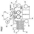
- optical document reader comprising:
- the optical document reader 30 comprises a hopper 31, a pick-up roller 32, a sheet separator 33, a feed roller 34, a transport route 35, a stacker 36, an optical document reader unit 37 that reads a front surface of a document sheet and an optical document reader unit 38 that reads a back surface of a document sheet.
- the optical document reader 30 is controlled by a host computer not shown in the diagram, and operates in the following manner.
- FIG. 2 is a side view of a sheet separator according to an embodiment of the present invention.
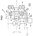
- FIG. 3 is a plan view of the sheet separator shown in FIG. 2.
- the sheet separator 33 is provided between the pick-up roller 32 and the feed roller 34. Additionally, the sheet separator 33 has a first separating mechanism 41 and a second separating mechanism 42.
- the first separating mechanism 41 is positioned near the pick-up roller 32.
- the second separating mechanism 42 is positioned downstream from the first separating mechanism 41 in terms of the direction of transport of the document sheet 21, that is, in the direction of arrow X1, at a distance L1 from the first separating mechanism 41.
- the distance L1 is substantially shorter than the length L of the document sheet 21.
- a direction indicated as X1-X2 in FIG. 3 is the longer, longitudinal direction of the sheet separator 33 and, at the same time, is both the direction of transport of the document sheet 21 and the lengthwise direction of the document sheet 21.
- a direction indicated as Y1-Y2 represents a lateral width direction of the sheet separator 33 as well as a lateral width of the document sheet 21.
- CL represents a hypothetical centerline extending along a center of the sheet separator 33 in the longitudinal X1-X2 direction.
- the first separating mechanism 41 comprises a first separating roller 50, a first torque roller 51, a pulse motor 52 that rotates the first separating roller 50, a first torque limiter 53 coupled to the first torque roller 51 that imparts a predetermined braking force to the first torque roller 51, and a first separation force application mechanism 54 that applies to the first torque roller 51 a separation force F that presses the first torque roller 51 against the first separating roller 50.
- the second separating mechanism 42 comprises two second separating rollers 55-1 and 55-2, two second torque rollers 56-1 and 56-2, a second torque limiter 57 that imparts a predetermined braking force to the two second torque rollers 56-1 and 56-2, and a second separation force application mechanism 58 that applies to the second torque rollers 56-1, 56-2 a separation force F that presses the second torque rollers 56-1, 56-2 against the second separating rollers 55-1, 55-2.
- the second separating rollers 55-1, 55-2 are rotated by the pulse motor 52 described above via a gear.
- the first separating roller 50 of the first separating mechanism 41 is positioned at a position P1 on the centerline CL described above, and acts upon a central portion of the sheet in the lateral direction thereof during separation.
- the two second separating rollers 55-1, 55-2 of the second separating mechanism 42 are positioned equidistant from and to either side of the centerline CL in the lateral Y1-Y2 direction at a distance a from the centerline CL, at positions P2-1 and P2-2. Additionally, the two second separating rollers 55-1, 55-2 are also offset in the lateral Y1-Y2 direction with respect to the position of the first separating roller 50, at positions near the respective Y1 and Y2 lateral edges of the document sheet 21.
- the first separating roller 50 is supported by a rotation shaft 60 via a one-way clutch 61 that transmits the counterclockwise rotation of the rotation shaft 60 to the first separating roller 50.
- the second separating rollers 55-1, 55-2 are jointly supported by a rotation shaft 62 via a one-way clutch 63 that transmits the counterclockwise rotation of the rotation shaft 62 to the second separating rollers 55-1, 55-2.
- a first gear 64 is fixedly mounted on the tip of the rotation shaft 60 and a second gear 65 is mounted on the tip of the rotation shaft 62.
- a gear 66 of the pulse motor 52 meshes with the first gear 64, with an idle gear 67 provided between the first gear 64 and the second gear 65.
- first separating roller 50 and the second separating rollers 55-1, 55-2 are such that a coefficient of friction ⁇ 2 between the first separating roller 50 and the document sheet 21 and a coefficient of friction ⁇ 3 between the second separating rollers 55-1, 55-2 and the document sheet 21 are greater than a coefficient of friction ⁇ 1 between two document sheets 21.
- the rotation shafts 60 and 62 are rotated in a counterclockwise direction, the first separating roller 50 and the second separating rollers 55-1, 55-2 are both rotated in the counterclockwise direction.
- the first separating roller 50 itself rotates and in turn rotates the first torque roller 51.
- the second separating rollers 55-1, 55-2 themselves rotate and in turn rotate the second torque rollers 56-1, 56-2, respectively.
- the pick-up roller 32 described previously normally picks up and sends onward only the uppermost document sheet 21-1.
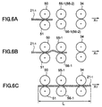
- the document sheet 21-1 is sandwiched between and driven by the first separating roller 50 and the first torque roller 51, is further sandwiched between and driven by the second separating rollers 55-1, 55-2 and second torque rollers 56-1, 56-2 and passes through the sheet separator 33 in the manner shown in FIGS 6A, 6B and 6C.
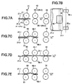
- the sheet separator 33 operates in the manner shown in FIGS. 7A, 7B, 7C, 7D and 7E.
- the leading edges of the two double-fed document sheets 21-1 and 21-2 reach the first separating mechanism 41, enter between the first separating roller 50 and the first torque roller 51, the first torque roller 51 separates from the first separating roller 50, the top sheet 21-1 contacts the first separating roller 50 and the bottom sheet 21-2 contacts the first torque roller 51.
- the coefficient of friction u 1 between the top sheet 21-1 and the bottom sheet 21-2 is smaller than the coefficient of friction ⁇ 4 between the bottom sheet 21-2 and the first torque roller 51.
- the top sheet 21-1 slides over the bottom sheet 21-2 while the bottom sheet 21-2 is braked by the frictional force exerted by the first torque roller 51 to which a braking force has been imparted by the first torque limiter 53.
- the progress of the second sheet 21-2 in the X1 direction is thereby halted, in a state in which the second sheet 21-2 is stopped at the first torque roller 51.
- the top sheet 21-1 begins to separate from the bottom sheet 21-2 as shown in FIGS. 7A and 7B.
- the first separating mechanism 41 of the sheet separator 33 acts to separate double-fed sheets.
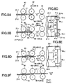
- FIG. 8A shows a state in which two sheets 21-1 and 21-2 are double-fed to the first separating mechanism 41, are not separated by the first separating mechanism 41 and therefore pass through the first separating mechanism 41 unseparated, in which case the unseparated sheets 21-1 and 21-2 head toward the second separating mechanism 42.
- the chief operation of the present invention is performed, that is, the top sheet 21-1 is pinched so as to form an upward bulge and is separated from the bottom sheet 21-2 as shown in FIGS. 8B and 8C.
- the coefficient of friction u 1 between the top sheet 21-1 and the bottom sheet 21-2 is less than the coefficient of friction ⁇ 5 between the bottom sheet 21-2 and the second torque rollers 56-1, 56-2.
- the top sheet 21-1 slides over the bottom sheet 21-2 while the bottom sheet 21-2 is braked by the frictional force exerted by the second torque rollers 56-1, 56-2 to which a braking force has been imparted by the second torque limiter 53.
- the progress of the second sheet 21-2 in the X1 direction is thereby halted, in a state in which the second sheet 21-2 is stopped at the second torque rollers 56-1, 56-2.
- the peripheral velocity V2 of the second separating rollers 55-1, 55-2 is slightly slower than the peripheral velocity V1 of the first separating roller 50.
- the second separating rollers 55-1, 55-2 press against positions Q2-1, Q2-2 near corners 21-1a, 21-1b along both lateral edges of the top sheet 21-1.
- the first separating roller 50 and the first torque roller 51 are pressing against the top sheet 21-1 at a position Q1 which is both offset in the X2 direction from positions Q2-1 and Q2-2 and is at a central position in the lateral direction of the top sheet 21-1.
- the three positions Q1, Q2-1 and Q2-2 form an isosceles triangle with position Q1 as the apex thereof.
- a force F10 appears to be exerted on positions Q2-1, Q2-2 of the top sheet 21-1 in the X2 direction while position Q1 appears to be fixed. It should be noted that the size of the force F10 corresponds to the difference between peripheral velocities V1 and V2 described above.
- the force F10 exerted on positions Q2-1, Q2-2 causes a compressive force to act upon a portion 21-1c of the top sheet 21-1 that lies between position Q1 on the one hand and positions Q2-1 and Q2-2 on the other in the X1-X2 direction.
- An upwardly projecting bulge portion is formed in portion 21-1c as indicated by reference numeral 70 in FIG. 8B, which upwardly projecting bulge portion 70 is indicated by the bulge mark 71 in FIG. 8C.
- positions Q2-1 and Q2-2 exerts a twisting force with respect to position Q1.
- positions Q2-1, Q2-2 are located near corner portions 21-1a and 21-1b of the top sheet 21-1, at which locations the top sheet is more easily separated from the bottom sheet. Accordingly, force F10 makes it easier to bend the central portion 21-1c upward into the bulge 70 described above.
- the top sheet 21-1 separates from the bottom sheet 21-1 to form a gap, then air is drawn into the gap to further separate the portions 21-1c from the bottom sheet 21-2, making the gap wide and thus weakening the force that causes the two sheets 21-1, 21-2 to stick together.
- the top sheet 21-1 slides over the top of the bottom sheet 21-1 in the X1 direction.
- a force that compresses the central portion 21-1c of the top sheet 21-1 between positions Q1 on the one hand and positions Q2-1, Q2-2 on the other continues to be exerted during the time in which the top sheet 21-1 is sliding over the bottom sheet 21-2 in the X1 direction, and consequently an upwardly bulging portion continues to be formed in portion 21-1c as shown in FIG. 8D, the force causing the two double-fed sheets 21-1 and 21-2 to stick together continues to weaken and the top sheet 21-1 continues to slide easily over and securely separate from the bottom sheet 21-2.
- the top sheet 21-1 is fed onward in the X1 direction by the feed roller 34 as shown in FIG. 8F.
- the peripheral velocity V3 of the feed roller 34 is faster than the peripheral velocity V1 of the first separating roller 50 as well as the peripheral velocity V2 of the second separating rollers 55-1, 55-2. Accordingly, the top sheet 21-1 is pulled by the feed roller 34, the first separating roller 50 as well as the second separating rollers 55-1, 55-2 are dragged by the top sheet 21-1 and are rotated faster than shafts 60, 62 while the one-way clutches 61, 63 spin freely, thus eliminating the above-described upwardly projecting bulge portion 70.
- the second torque rollers 56-1, 56-2 have a comparatively long dimension S so as to cover the variety of document sizes to be handled by the sheet separator 33.
- a click-lock mechanism 80 comprising a coil spring 81 and a pin 82 is provided on the second separating roller 55-1, and annular grooves 61a are formed at regular intervals on the rotating shaft 61. Accordingly, the second separating roller 55-1 can be moved in the Y1-Y2 direction and fixed at a desired position.
- the other second separating roller 55-2 has a structure similar to that of the second separating roller 55-1 described above.
- a link mechanism operated by a lever or the like may be provided in place of the above-described mechanism so as to move the two second separating rollers 55-1, 55-2 symmetrically with respect to the centerline CL described previously.
- a mechanism may be provided in which the two second separating rollers 55-1, 55-2 may be moved by a motor.
- the present invention is not limited to the separation of documents or document sheets but may be used to separate ordinary sheets of paper as well.
Abstract
Description
- The present invention relates generally to a sheet separator, and more particularly, to a document sheet separator adapted for use in an optical document reader.
- Generally, an optical document reader is an apparatus in which documents are sent or fed one sheet at a time from the top of a stack of document sheets set in the hopper of the optical document reader to an optical document reader unit that optically reads information printed on the document. Typically, such optical document readers include a document separator for separating sheets of documents into single sheets whenever two sheets are fed from the hopper at the same time, that is, whenever a double-feed occurs. Obviously, such a double-feed is undesirable and should be avoided wherever possible.
- At present the range of types of materials from which documents are made is very large. In some cases, these materials from which documents are made are such that single sheets of such documents tend to stick together, making a double-feed more likely to occur. As a result, a sheet separator with an improved ability to separate such double-fed sheets of documents into single sheets is needed.
- FIGS. 1A and 1B show an example of the prior art, that is, a conventional sheet separator. As shown in FIGS. 1A and 1B, the conventional sheet separator 10A consists of one separating
roller 11, onetorque roller 12, apulse motor 13 that rotates the separatingroller 11 and a separationforce application mechanism 14 that imparts a separation force F to thetorque roller 12, with thetorque roller 12 being pressed against the separatingroller 11. Thetorque roller 12 is coupled to a torque limiter not shown in the diagram so that thetorque roller 12 remains stopped even if a certain amount of torque is applied and begins to rotate only when a predetermined amount of torque is applied. The separationforce application mechanism 14 can be used to adjust the separation force F. - The above-described
conventional sheet separator 10 typically remains inactive unless a double-feed occurs, that is, when the first document sheet 21-1 is fed onward by a pick-up roller 22 and a second document sheet 21-2 sticks to the back of a first document sheet 21-1 and is dragged together with the first document sheet 21-1, the first sheet 21-1 being the sheet positioned at the top of astack 21 of multiple document sheets set in ahopper 20. - In the event of a double-feed like that described above, a forward longitudinal edge of the second sheet 21-2, which is on the bottom, is braked by the stopped
torque roller 12 and the forward advance of the second sheet 21-2 is retarded thereby. At the same time, the first sheet 21-1, which is on the top and against which a feed force is exerted by the separatingroller 11 , slides over and separates from the second sheet 21-2 so that only the first sheet 21-1 is fed onward to the feed roller 23 by the separatingroller 11. After the first sheet 21-1 is fed onward the second sheet, which had been braked by thetorque roller 12 and any forward progress retarded thereby, is fed onward by the separatingroller 11, with thetorque roller 12 being rotated by the force of frictional contact with the second sheet 21-2. - It should be noted that, for clarity of illustration only, in FIG. 1B the second sheet 21-2 on the bottom is shown slightly smaller than the first sheet 21-1 on the top. A similar approach is taken with respect to FIGS. 7B, 8C and 8E.
- However, a problem arises with the
conventional sheet separator 10 like that described above insofar as theconventional sheet separator 10 is not fully capable of separating double-fed sheets. As a result, when the coefficient of friction between sheets is large, that is, when it is hard to separate the sheets set in thehopper 20, double-fed sheets are not separated but might pass through thedocument sheet separator 10 in that double-fed state. - Typically, the coefficient of friction between two documents stuck together differs depending on the type of documents in question, so the separation
force application mechanism 14 described above is used to adjust the separation force F downward, that is, to reduce the separation force F in order to make it easier to separate the sheets. However, even with this adjustment of the separation force F depending on the type of paper used to make the document sheets it sometimes happens that document sheets are double-fed through thesheet separator 10. - Accordingly, it is an object of the present invention to provide an improved and useful document sheet separator in which the above-described disadvantage is eliminated.
- The above-described object of the present invention is achieved by a sheet separator that separates sheets of documents supplied as a stack into single sheets, the sheet separator comprising:
- a first separating mechanism having a first separating roller; and
- a second separating mechanism having second separating rollers,
- the second separating mechanism provided at a position downstream from a position of the first separating mechanism.
-
- According to the invention described above, the second separating mechanism separates those sheets that are fed onward without being separated by the first separating mechanism.
- Additionally, the above-described object of the present invention is also achieved by the sheet separator as described above, wherein a peripheral velocity of the second separating rollers is set lower than a peripheral velocity of the first separating roller.
- According to the invention described above, setting the peripheral speed of the second separating rollers slower than the peripheral speed of the first separating roller causes a compressive force to act on the top sheet of two sheets double-fed onward without being separated by the first separating mechanism, causing such a top sheet to form an upward bulge.
- Additionally, the above-described object of the present invention is also achieved by the sheet separator as described above, wherein the first separating roller is positioned so as to act upon a central portion in a lateral direction of a sheet transported thereto and the second separating rollers are positioned so as to act upon edge surface portions in the lateral direction of the sheet transported thereto.
- According to the invention described above, positioning the second separating rollers so as to act upon edge portions of the sheet transported thereto causes the separation force to act on locations near the corners of the top sheet of two double-fed sheets, at which locations the top sheet is more easily separated from the bottom sheet.
- Additionally, the above-described object of the present invention is also achieved by the sheet separator as described above, wherein:
- a peripheral velocity of the second separating roller is set lower than a peripheral velocity of the first separating roller;
- the first separating roller is positioned so as to act upon a central portion in a lateral direction of a sheet transported thereto; and
- the second separating rollers are positioned so as to act upon edge surface portions in the lateral direction of the sheet transported thereto.
-
- According to the invention described above, setting the peripheral speed of the second separating rollers slower than the peripheral speed of the first separating roller causes a compressive force to act on a portion of the top sheet of two sheets double-fed onward without being separated by the first separating mechanism that lies between the first separating roller and the second separating rollers, causing such a top sheet to form an upward bulge.
- Additionally, as described above, positioning the second separating rollers so as to act upon edge portions of the sheet transported thereto causes the separation force to act on locations near the corners of the top sheet of two double-fed sheets, at which locations the top sheet is more easily separated from the bottom sheet.
- Additionally, positioning the first separating roller so as to act upon a central portion of a sheet transported thereto causes the separation force applied by the second separating rollers to become a twisting force with respect to the location at which the first separating roller exerts a separation force.
- Additionally, the above-described object of the present invention is also achieved by the sheet separator as described above, wherein the second separating rollers are supported so that positions of the second separating rollers in a lateral direction of a sheet transported thereto can be changed.
- According to the invention described above, the document sheet separator according to the present invention can accommodate a plurality of different sizes of paper.
- Additionally, the above-described object of the present invention is also achieved by the sheet separator as described above, wherein a distance between the first separating mechanism and the second separating mechanism is shorter than a longitudinal length of the sheet.
- Additionally, the above-described object of the present invention is also achieved by an optical document reader comprising:
- a hopper, to which a plurality of sheets can be set;
- a sheet separator that separates sheets of documents supplied as a stack into single sheets;
- a feed roller that transports documents;
- an optical document reading unit that optically reads data inscribed on the documents; and
- a stacker that stacks and outputs documents from which data has been optically read by the optical document reading unit,
- the sheet separator comprising:
- a first separating mechanism having a first separating roller; and
- a second separating mechanism having second separating rollers,
- the second separating mechanism provided at a position downstream from a position of the first separating mechanism.
-
- According to the invention described above a double-feed is less likely to occur and, accordingly, a more reliable optical document reader can be attained.
- Other objects, features and advantages of the present invention will become more apparent from the following detailed description when read in conjunction with the accompanying drawings.
-
- FIGS. 1A and 1B show a conventional sheet separator;
- FIG. 2 is a side view of a sheet separator according to an embodiment of the present invention;
- FIG. 3 is a plan view of the sheet separator shown in FIG. 2;
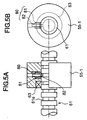
- FIG. 4 is a view of the second separating mechanism as seen from the feed roller side;
- FIGS. 5A and 5B show the relation between the second separating rollers and the rotary shaft;
- FIGS. 6A, 6B and 6C are diagrams showing the operation of the sheet separator when documents are supplied to it one sheet at a time;
- FIGS. 7A, 7B, 7C, 7D and 7E are diagrams showing the operation of the sheet separator when documents are double-fed;
- FIGS. 8A, 8B, 8C, 8D, 8E and 8F are diagrams showing the operation of the sheet separator when documents are double-fed without being separated by the first separating mechanism; and
- FIG. 9 is a schematic diagram of an optical document reader adapting the sheet separator shown in Fig. 2.
-
- For clarity of explanation, a description will first be given of an
optical document reader 30 incorporating a sheet separator according to an embodiment of the present invention, with reference to FIG. 9. - Generally, as shown in FIG. 9, the
optical document reader 30 comprises ahopper 31, a pick-uproller 32, asheet separator 33, afeed roller 34, atransport route 35, astacker 36, an opticaldocument reader unit 37 that reads a front surface of a document sheet and an opticaldocument reader unit 38 that reads a back surface of a document sheet. - The
optical document reader 30 is controlled by a host computer not shown in the diagram, and operates in the following manner. -
Multiple document sheets 21 set or stacked in thehopper 20 are taken one sheet at a time from the top of the stack, picked up from the hopper and sent in a direction indicated in the diagram as arrow X1 by the pick-uproller 32, transported or fed by thefeed roller 34 driven by amotor 39, the information printed on the front surface of the document is read by the opticaldocument reader unit 37 and the information printed on the back surface of the document is read by the opticaldocument reader unit 38. Thereafter the document is ejected to thestacker 36 via thetransport route 35. As shown in FIGS. 6C and 7B, respectively, thedocument sheet 21 has a length L and a width W. - A description will now be given of the
sheet separator 33 according to a first embodiment of the present invention, with reference to FIGS. 2 and 3. - FIG. 2 is a side view of a sheet separator according to an embodiment of the present invention. FIG. 3 is a plan view of the sheet separator shown in FIG. 2. As shown in FIGS. 2 and 3, the
sheet separator 33 is provided between the pick-uproller 32 and thefeed roller 34. Additionally, thesheet separator 33 has afirst separating mechanism 41 and asecond separating mechanism 42. - The
first separating mechanism 41 is positioned near the pick-uproller 32. Thesecond separating mechanism 42 is positioned downstream from thefirst separating mechanism 41 in terms of the direction of transport of thedocument sheet 21, that is, in the direction of arrow X1, at a distance L1 from thefirst separating mechanism 41. The distance L1 is substantially shorter than the length L of thedocument sheet 21. - For clarity of explanation, it should be noted that a direction indicated as X1-X2 in FIG. 3 is the longer, longitudinal direction of the
sheet separator 33 and, at the same time, is both the direction of transport of thedocument sheet 21 and the lengthwise direction of thedocument sheet 21. A direction indicated as Y1-Y2 represents a lateral width direction of thesheet separator 33 as well as a lateral width of thedocument sheet 21. CL represents a hypothetical centerline extending along a center of thesheet separator 33 in the longitudinal X1-X2 direction. - The
first separating mechanism 41 comprises afirst separating roller 50, afirst torque roller 51, apulse motor 52 that rotates thefirst separating roller 50, afirst torque limiter 53 coupled to thefirst torque roller 51 that imparts a predetermined braking force to thefirst torque roller 51, and a first separationforce application mechanism 54 that applies to the first torque roller 51 a separation force F that presses thefirst torque roller 51 against thefirst separating roller 50. - The
second separating mechanism 42 comprises two second separating rollers 55-1 and 55-2, two second torque rollers 56-1 and 56-2, asecond torque limiter 57 that imparts a predetermined braking force to the two second torque rollers 56-1 and 56-2, and a second separationforce application mechanism 58 that applies to the second torque rollers 56-1, 56-2 a separation force F that presses the second torque rollers 56-1, 56-2 against the second separating rollers 55-1, 55-2. The second separating rollers 55-1, 55-2 are rotated by thepulse motor 52 described above via a gear. - As shown in FIG. 3, the
first separating roller 50 of thefirst separating mechanism 41 is positioned at a position P1 on the centerline CL described above, and acts upon a central portion of the sheet in the lateral direction thereof during separation. The two second separating rollers 55-1, 55-2 of thesecond separating mechanism 42 are positioned equidistant from and to either side of the centerline CL in the lateral Y1-Y2 direction at a distance a from the centerline CL, at positions P2-1 and P2-2. Additionally, the two second separating rollers 55-1, 55-2 are also offset in the lateral Y1-Y2 direction with respect to the position of thefirst separating roller 50, at positions near the respective Y1 and Y2 lateral edges of thedocument sheet 21. - The
first separating roller 50 is supported by arotation shaft 60 via a one-way clutch 61 that transmits the counterclockwise rotation of therotation shaft 60 to thefirst separating roller 50. Similarly, the second separating rollers 55-1, 55-2 are jointly supported by arotation shaft 62 via a one-way clutch 63 that transmits the counterclockwise rotation of therotation shaft 62 to the second separating rollers 55-1, 55-2. - A
first gear 64 is fixedly mounted on the tip of therotation shaft 60 and asecond gear 65 is mounted on the tip of therotation shaft 62. Agear 66 of thepulse motor 52 meshes with thefirst gear 64, with anidle gear 67 provided between thefirst gear 64 and thesecond gear 65. - Additionally, the surfaces of first separating
roller 50 and the second separating rollers 55-1, 55-2 are such that a coefficient of friction µ2 between thefirst separating roller 50 and thedocument sheet 21 and a coefficient of friction µ3 between the second separating rollers 55-1, 55-2 and thedocument sheet 21 are greater than a coefficient of friction µ1 between twodocument sheets 21. - A description will now be given of an operation of the
sheet separator 33 having the structure described above. - When the
pulse motor 52 is driven, therotation shafts first separating roller 50 and the second separating rollers 55-1, 55-2 are both rotated in the counterclockwise direction. Thefirst separating roller 50 itself rotates and in turn rotates thefirst torque roller 51. The second separating rollers 55-1, 55-2 themselves rotate and in turn rotate the second torque rollers 56-1, 56-2, respectively. The number of teeth N1 of thefirst gear 64 and the number of teeth N2 of thesecond gear 65 are set appropriately. Accordingly, the peripheral velocity V2 of the second separating rollers 55-1, 55-2 is slightly slower than the peripheral velocity V1 of thefirst separating roller 50, such that - The pick-up
roller 32 described previously normally picks up and sends onward only the uppermost document sheet 21-1. The document sheet 21-1 is sandwiched between and driven by thefirst separating roller 50 and thefirst torque roller 51, is further sandwiched between and driven by the second separating rollers 55-1, 55-2 and second torque rollers 56-1, 56-2 and passes through thesheet separator 33 in the manner shown in FIGS 6A, 6B and 6C. - However, in the event that two document sheets 21-1 and 21-2 are stuck together one atop the other and double-fed from the
hopper 20, then thesheet separator 33 operates in the manner shown in FIGS. 7A, 7B, 7C, 7D and 7E. - First, the leading edges of the two double-fed document sheets 21-1 and 21-2 reach the
first separating mechanism 41, enter between thefirst separating roller 50 and thefirst torque roller 51, thefirst torque roller 51 separates from thefirst separating roller 50, the top sheet 21-1 contacts thefirst separating roller 50 and the bottom sheet 21-2 contacts thefirst torque roller 51. - In such a state, the coefficient of friction u1 between the top sheet 21-1 and the bottom sheet 21-2 is smaller than the coefficient of friction µ4 between the bottom sheet 21-2 and the
first torque roller 51. - As a result, the top sheet 21-1 slides over the bottom sheet 21-2 while the bottom sheet 21-2 is braked by the frictional force exerted by the
first torque roller 51 to which a braking force has been imparted by thefirst torque limiter 53. The progress of the second sheet 21-2 in the X1 direction is thereby halted, in a state in which the second sheet 21-2 is stopped at thefirst torque roller 51. As a result, the top sheet 21-1 begins to separate from the bottom sheet 21-2 as shown in FIGS. 7A and 7B. - Further, once the top sheet 21-1 is fed onward as shown in FIGS. 7C and 7D the second sheet 21-2, which had been stopped at the
first torque roller 51, is fed onward as shown in FIG. 7E. - In short, the
first separating mechanism 41 of thesheet separator 33 acts to separate double-fed sheets. - Next, a description is given of a state in which two sheets 21-1 and 21-2 are stuck together so tightly that the two sheets 21-1 and 21-2 are not separated by the
first separating mechanism 41 but pass through thefirst separating mechanism 41 unseparated, with reference to FIGS. 8A, 8B, 8C, 8D, 8E and 8F. - FIG. 8A shows a state in which two sheets 21-1 and 21-2 are double-fed to the
first separating mechanism 41, are not separated by thefirst separating mechanism 41 and therefore pass through thefirst separating mechanism 41 unseparated, in which case the unseparated sheets 21-1 and 21-2 head toward thesecond separating mechanism 42. - When the two double-fed sheets 21-1 and 21-2, which are stuck together one atop the other, arrive at the
second separating mechanism 42, the lead edges of the double-fed sheets 21-1 and 21-2 enter between the second separating rollers 55-1, 55-2 and the second torque rollers 56-1, 56-2, the second torque rollers 56-1, 56-2 separate from the second separating rollers 55-1, 55-2, the top sheet 21-1 contacts the second separating rollers 55-1, 55-2 and the bottom sheet 21-2 contacts the second torque rollers 56-1, 56-2 as indicated by the dotted chain lines in FIG. 8A. - Directly thereafter, the chief operation of the present invention is performed, that is, the top sheet 21-1 is pinched so as to form an upward bulge and is separated from the bottom sheet 21-2 as shown in FIGS. 8B and 8C.
- In the state shown in FIGS. 8B and 8C described above, the coefficient of friction u1 between the top sheet 21-1 and the bottom sheet 21-2 is less than the coefficient of friction µ5 between the bottom sheet 21-2 and the second torque rollers 56-1, 56-2.
- As a result, the top sheet 21-1 slides over the bottom sheet 21-2 while the bottom sheet 21-2 is braked by the frictional force exerted by the second torque rollers 56-1, 56-2 to which a braking force has been imparted by the
second torque limiter 53. The progress of the second sheet 21-2 in the X1 direction is thereby halted, in a state in which the second sheet 21-2 is stopped at the second torque rollers 56-1, 56-2. - Additionally, the peripheral velocity V2 of the second separating rollers 55-1, 55-2 is slightly slower than the peripheral velocity V1 of the
first separating roller 50. Moreover, as shown in FIG. 8C, the second separating rollers 55-1, 55-2 press against positions Q2-1, Q2-2 near corners 21-1a, 21-1b along both lateral edges of the top sheet 21-1. Thefirst separating roller 50 and thefirst torque roller 51 are pressing against the top sheet 21-1 at a position Q1 which is both offset in the X2 direction from positions Q2-1 and Q2-2 and is at a central position in the lateral direction of the top sheet 21-1. It should be noted that the three positions Q1, Q2-1 and Q2-2 form an isosceles triangle with position Q1 as the apex thereof. - Accordingly, when viewed from position Q1 a force F10 appears to be exerted on positions Q2-1, Q2-2 of the top sheet 21-1 in the X2 direction while position Q1 appears to be fixed. It should be noted that the size of the force F10 corresponds to the difference between peripheral velocities V1 and V2 described above.
- The force F10 exerted on positions Q2-1, Q2-2 causes a compressive force to act upon a portion 21-1c of the top sheet 21-1 that lies between position Q1 on the one hand and positions Q2-1 and Q2-2 on the other in the X1-X2 direction. An upwardly projecting bulge portion is formed in portion 21-1c as indicated by
reference numeral 70 in FIG. 8B, which upwardly projectingbulge portion 70 is indicated by thebulge mark 71 in FIG. 8C. - As will be appreciated by those skilled in the art, the force F10 exerted at positions Q2-1 and Q2-2 exerts a twisting force with respect to position Q1. Moreover, as noted previously, positions Q2-1, Q2-2 are located near corner portions 21-1a and 21-1b of the top sheet 21-1, at which locations the top sheet is more easily separated from the bottom sheet. Accordingly, force F10 makes it easier to bend the central portion 21-1c upward into the
bulge 70 described above. - Once the portion 21-1c of the top sheet 21-1 is bent upward into the
bulge 70 described above, the top sheet 21-1 separates from the bottom sheet 21-1 to form a gap, then air is drawn into the gap to further separate the portions 21-1c from the bottom sheet 21-2, making the gap wide and thus weakening the force that causes the two sheets 21-1, 21-2 to stick together. - Next, as shown in FIGS. 8D and 8E, the top sheet 21-1 slides over the top of the bottom sheet 21-1 in the X1 direction. A force that compresses the central portion 21-1c of the top sheet 21-1 between positions Q1 on the one hand and positions Q2-1, Q2-2 on the other continues to be exerted during the time in which the top sheet 21-1 is sliding over the bottom sheet 21-2 in the X1 direction, and consequently an upwardly bulging portion continues to be formed in portion 21-1c as shown in FIG. 8D, the force causing the two double-fed sheets 21-1 and 21-2 to stick together continues to weaken and the top sheet 21-1 continues to slide easily over and securely separate from the bottom sheet 21-2.
- Once the leading edge of the top sheet 21-1 reaches the
feed roller 34, the top sheet 21-1 is fed onward in the X1 direction by thefeed roller 34 as shown in FIG. 8F. It should be noted that the peripheral velocity V3 of thefeed roller 34 is faster than the peripheral velocity V1 of thefirst separating roller 50 as well as the peripheral velocity V2 of the second separating rollers 55-1, 55-2. Accordingly, the top sheet 21-1 is pulled by thefeed roller 34, thefirst separating roller 50 as well as the second separating rollers 55-1, 55-2 are dragged by the top sheet 21-1 and are rotated faster thanshafts way clutches bulge portion 70. - Once the top sheet 21-1 is separated and fed onward, the bottom sheet 21-2, which had been stopped at the second torque rollers 56-1, 56-2 is fed onward as shown in FIG. 7E.
- Next, a description will be given of the second separating rollers 55-1, 55-2 and the second torque rollers 56-1, 56-2, with reference to FIGS. 4 and FIGS. 5A and 5B.
- As an initial matter, it should be noted that the second torque rollers 56-1, 56-2 have a comparatively long dimension S so as to cover the variety of document sizes to be handled by the
sheet separator 33. - Additionally, a click-
lock mechanism 80 comprising acoil spring 81 and apin 82 is provided on the second separating roller 55-1, andannular grooves 61a are formed at regular intervals on therotating shaft 61. Accordingly, the second separating roller 55-1 can be moved in the Y1-Y2 direction and fixed at a desired position. - Additionally, it should be noted that the other second separating roller 55-2 has a structure similar to that of the second separating roller 55-1 described above.
- Accordingly, by changing the positions of the second separating rollers 55-1, 55-2 it is possible to accommodate a variety of different document sizes.
- It should be noted that, alternatively, a link mechanism operated by a lever or the like may be provided in place of the above-described mechanism so as to move the two second separating rollers 55-1, 55-2 symmetrically with respect to the centerline CL described previously. Or, alternatively, a mechanism may be provided in which the two second separating rollers 55-1, 55-2 may be moved by a motor.
- In addition, it should be noted that the present invention is not limited to the separation of documents or document sheets but may be used to separate ordinary sheets of paper as well.
- The above description is provided in order to enable any person skilled in the art to make and use the invention and sets forth the best mode contemplated by the inventors of carrying out the invention.
- The present invention is not limited to the specifically disclosed embodiment, and variations and modifications may be made without departing from the scope of the present invention.
- The present application is based on Japanese Priority Application No. 11-230560, filed on August 17, 1999, the entire contents of which are hereby incorporated by reference.
Claims (7)
- A sheet separator (33) that separates sheets of documents (21) supplied as a stack into single sheets, the sheet separator (33) characterized by having:a first separating mechanism (41) having a first separating roller (50); anda second separating mechanism (42) having second separating rollers (55-1, 55-2),the second separating mechanism (42) provided at a position downstream from a position of the first separating mechanism (41).
- The sheet separator (33) as claimed in claim 1, characterized in that a peripheral velocity of the second separating rollers (55-1, 55-2) is set lower than a peripheral velocity of the first separating roller (50).
- The sheet separator (33) as claimed in claim 1, characterized in that the first separating roller (50) is positioned so as to act upon a central portion in a lateral direction of a sheet (21-1) transported thereto and the second separating rollers (55-1, 55-2) are positioned so as to act upon edge surface portions in the lateral direction of the sheet (21-1) transported thereto.
- The sheet separator (33) as claimed in claim 1, characterized in that:a peripheral velocity of the second separating roller (55-1, 55-2) is set lower than a peripheral velocity of the first separating roller (50);the first separating roller (50) is positioned so as to act upon a central portion in a lateral direction of a sheet (21-1) transported thereto; andthe second separating rollers (55-1, 55-2) are positioned so as to act upon edge surface portions in the lateral direction of the sheet (21-1) transported thereto.
- The sheet separator (33) as claimed in claim 1, characterized in that the second separating rollers (55-1, 55-2) are supported so that positions of the second separating rollers (55-1, 55-2) in a lateral direction of a sheet (21-1) transported thereto can be changed.
- The sheet separator (33) as claimed in claim 1, characterized in that a distance between the first separating mechanism (41) and the second separating mechanism (42) is shorter than a longitudinal length of the sheet (21).
- An optical document reader (30) characterized by having:a hopper (31), to which a plurality of sheets (21) can be set;a sheet separator (33) that separates sheets of documents (21) supplied as a stack into single sheets;a feed roller (34) that transports documents;an optical document reading unit (38) that optically reads data inscribed on the documents; anda stacker (36) that stacks and outputs documents from which data has been optically read by the optical document reading unit (38),the sheet separator (33) characterized by having:a first separating mechanism (41) having a first separating roller (50); anda second separating mechanism (42) having second separating rollers(55-1, 55-2),the second separating mechanism (42) provided at a position downstream from a position of the first separating mechanism (41).
Applications Claiming Priority (2)
| Application Number | Priority Date | Filing Date | Title |
|---|---|---|---|
| JP23056099A JP3661839B2 (en) | 1999-08-17 | 1999-08-17 | Paper separating device and optical reader |
| JP23056099 | 1999-08-17 |
Publications (2)
| Publication Number | Publication Date |
|---|---|
| EP1077190A2 true EP1077190A2 (en) | 2001-02-21 |
| EP1077190A3 EP1077190A3 (en) | 2002-01-30 |
Family
ID=16909678
Family Applications (1)
| Application Number | Title | Priority Date | Filing Date |
|---|---|---|---|
| EP00302343A Withdrawn EP1077190A3 (en) | 1999-08-17 | 2000-03-22 | Sheet separator |
Country Status (3)
| Country | Link |
|---|---|
| US (1) | US6345817B1 (en) |
| EP (1) | EP1077190A3 (en) |
| JP (1) | JP3661839B2 (en) |
Cited By (1)
| Publication number | Priority date | Publication date | Assignee | Title |
|---|---|---|---|---|
| EP1512649A2 (en) | 2003-09-03 | 2005-03-09 | Kabushiki Kaisha Toshiba | Paper sheet separation and transfer apparatus |
Families Citing this family (4)
| Publication number | Priority date | Publication date | Assignee | Title |
|---|---|---|---|---|
| JP2002347959A (en) * | 2001-05-22 | 2002-12-04 | Glory Ltd | Paper sheet feeder |
| US7810811B2 (en) * | 2007-03-30 | 2010-10-12 | Canon Kabushiki Kaisha | Sheet conveying apparatus and image forming apparatus |
| JP5814166B2 (en) * | 2012-03-09 | 2015-11-17 | 株式会社Pfu | Medium supply device |
| JP2015058992A (en) * | 2013-09-17 | 2015-03-30 | 沖電気工業株式会社 | Medium delivery device and medium transaction device |
Citations (3)
| Publication number | Priority date | Publication date | Assignee | Title |
|---|---|---|---|---|
| US4030723A (en) * | 1975-12-15 | 1977-06-21 | Pitney-Bowes, Inc. | Vacuum-controlled, sheet-material separator and feeder system |
| JPS62235143A (en) * | 1986-04-07 | 1987-10-15 | Nippon Seimitsu Kogyo Kk | Sheet feed device |
| JPH08175693A (en) * | 1994-12-26 | 1996-07-09 | Canon Inc | Sheet feeder and image reader |
Family Cites Families (6)
| Publication number | Priority date | Publication date | Assignee | Title |
|---|---|---|---|---|
| EP0047541B1 (en) * | 1980-09-08 | 1984-10-03 | Agfa-Gevaert N.V. | Dispenser for dispensing photographic sheets from a stack |
| US4690392A (en) * | 1984-09-24 | 1987-09-01 | Xerox Corporation | Envelope configuration for use in a high speed copier with envelope printing capability |
| JPH05116810A (en) | 1991-10-30 | 1993-05-14 | Ricoh Co Ltd | Automatic sheet feeder |
| JP3149139B2 (en) | 1992-02-06 | 2001-03-26 | 株式会社リコー | Paper feeder |
| US5575466A (en) * | 1994-11-21 | 1996-11-19 | Unisys Corporation | Document transport with variable pinch-roll force for gap adjust |
| JP2659344B2 (en) | 1995-02-10 | 1997-09-30 | 日本電気ロボットエンジニアリング株式会社 | Friction feeding mechanism for paper sheets |
-
1999
- 1999-08-17 JP JP23056099A patent/JP3661839B2/en not_active Expired - Fee Related
-
2000
- 2000-03-21 US US09/531,890 patent/US6345817B1/en not_active Expired - Fee Related
- 2000-03-22 EP EP00302343A patent/EP1077190A3/en not_active Withdrawn
Patent Citations (3)
| Publication number | Priority date | Publication date | Assignee | Title |
|---|---|---|---|---|
| US4030723A (en) * | 1975-12-15 | 1977-06-21 | Pitney-Bowes, Inc. | Vacuum-controlled, sheet-material separator and feeder system |
| JPS62235143A (en) * | 1986-04-07 | 1987-10-15 | Nippon Seimitsu Kogyo Kk | Sheet feed device |
| JPH08175693A (en) * | 1994-12-26 | 1996-07-09 | Canon Inc | Sheet feeder and image reader |
Non-Patent Citations (2)
| Title |
|---|
| PATENT ABSTRACTS OF JAPAN vol. 012, no. 105 (M-681), 6 April 1988 (1988-04-06) -& JP 62 235143 A (NIPPON SEIMITSU KOGYO KK), 15 October 1987 (1987-10-15) * |
| PATENT ABSTRACTS OF JAPAN vol. 1996, no. 11, 29 November 1996 (1996-11-29) -& JP 08 175693 A (CANON INC), 9 July 1996 (1996-07-09) * |
Cited By (10)
| Publication number | Priority date | Publication date | Assignee | Title |
|---|---|---|---|---|
| EP1512649A2 (en) | 2003-09-03 | 2005-03-09 | Kabushiki Kaisha Toshiba | Paper sheet separation and transfer apparatus |
| EP1512649A3 (en) * | 2003-09-03 | 2007-06-20 | Kabushiki Kaisha Toshiba | Paper sheet separation and transfer apparatus |
| US7270326B2 (en) | 2003-09-03 | 2007-09-18 | Kabushiki Kaisha Toshiba | Paper sheet separation and transfer apparatus |
| US7416180B2 (en) | 2003-09-03 | 2008-08-26 | Kabushiki Kaisha Toshiba | Paper sheet separation and transfer apparatus |
| EP2116492A1 (en) * | 2003-09-03 | 2009-11-11 | Kabushiki Kaisha Toshiba | Paper sheet separation and transfer apparatus |
| EP2116493A1 (en) * | 2003-09-03 | 2009-11-11 | Kabushiki Kaisha Toshiba | Paper sheet separation and transfer apparatus |
| US7717416B2 (en) | 2003-09-03 | 2010-05-18 | Kabushiki Kaisha Toshiba | Paper sheet separation and transfer apparatus |
| EP2275368A1 (en) * | 2003-09-03 | 2011-01-19 | Kabushiki Kaisha Toshiba | Paper sheet separation and transfer apparatus |
| EP2275369A1 (en) * | 2003-09-03 | 2011-01-19 | Kabushiki Kaisha Toshiba | Paper sheet separation and transfer apparatus |
| EP2371747A1 (en) * | 2003-09-03 | 2011-10-05 | Kabushiki Kaisha Toshiba | Paper sheet separation and transfer apparatus |
Also Published As
| Publication number | Publication date |
|---|---|
| US6345817B1 (en) | 2002-02-12 |
| JP2001048367A (en) | 2001-02-20 |
| JP3661839B2 (en) | 2005-06-22 |
| EP1077190A3 (en) | 2002-01-30 |
Similar Documents
| Publication | Publication Date | Title |
|---|---|---|
| JPH0986705A (en) | Automatic paper feeder | |
| US6824131B2 (en) | Method and apparatus for image forming and effectively performing sheet feeding using a sheet feed roller and a tilt member | |
| US20070096384A1 (en) | Automatic document feeder | |
| EP1077190A2 (en) | Sheet separator | |
| US10183824B2 (en) | Sheet feeding apparatus, image reading apparatus and image forming apparatus with sheet feeding apparatus | |
| JP2008044708A (en) | Paper sheet separation and delivery mechanism | |
| JPS6339497B2 (en) | ||
| CN1406848A (en) | Paper feeder of manuscript | |
| JPH0676148B2 (en) | Sheet material feeder | |
| JP5488794B2 (en) | Medium feeding device and recording device | |
| JPH0840577A (en) | Sheet material feeding device | |
| JPH0246494B2 (en) | SHOKYUSOSOCHI | |
| JPH03232632A (en) | Card feed device | |
| JP4249050B2 (en) | Paper feeding device and image forming apparatus | |
| JP2001063854A (en) | Paper feeding device | |
| JP5843881B2 (en) | Document processing apparatus and document processing method | |
| JP2704031B2 (en) | Paper sheet take-out device | |
| JP2542803Y2 (en) | Automatic paper feeder | |
| JPH0813565B2 (en) | Automatic paper feed mechanism | |
| JP3592198B2 (en) | Paper storage box with paper separation function | |
| JPH0625242U (en) | Paper separation device | |
| JPH0412036Y2 (en) | ||
| JP4067941B2 (en) | Sheet material feeding method, feeding device, and image forming apparatus including the same | |
| EP1634829B1 (en) | Sheet separator/feeder | |
| JP2003137458A (en) | Skew compensation device and sheet processing device equipped with it |
Legal Events
| Date | Code | Title | Description |
|---|---|---|---|
| PUAI | Public reference made under article 153(3) epc to a published international application that has entered the european phase |
Free format text: ORIGINAL CODE: 0009012 |
|
| AK | Designated contracting states |
Kind code of ref document: A2 Designated state(s): AT BE CH CY DE DK ES FI FR GB GR IE IT LI LU MC NL PT SE Kind code of ref document: A2 Designated state(s): DE GB |
|
| AX | Request for extension of the european patent |
Free format text: AL;LT;LV;MK;RO;SI |
|
| PUAL | Search report despatched |
Free format text: ORIGINAL CODE: 0009013 |
|
| AK | Designated contracting states |
Kind code of ref document: A3 Designated state(s): AT BE CH CY DE DK ES FI FR GB GR IE IT LI LU MC NL PT SE |
|
| AX | Request for extension of the european patent |
Free format text: AL;LT;LV;MK;RO;SI |
|
| RAP1 | Party data changed (applicant data changed or rights of an application transferred) |
Owner name: PFU LIMITED |
|
| RAP1 | Party data changed (applicant data changed or rights of an application transferred) |
Owner name: PFU LIMITED |
|
| 17P | Request for examination filed |
Effective date: 20020729 |
|
| AKX | Designation fees paid |
Free format text: DE GB |
|
| 17Q | First examination report despatched |
Effective date: 20030808 |
|
| STAA | Information on the status of an ep patent application or granted ep patent |
Free format text: STATUS: THE APPLICATION IS DEEMED TO BE WITHDRAWN |
|
| 18D | Application deemed to be withdrawn |
Effective date: 20031219 |