EP2275369A1 - Paper sheet separation and transfer apparatus - Google Patents
Paper sheet separation and transfer apparatus Download PDFInfo
- Publication number
- EP2275369A1 EP2275369A1 EP10185786A EP10185786A EP2275369A1 EP 2275369 A1 EP2275369 A1 EP 2275369A1 EP 10185786 A EP10185786 A EP 10185786A EP 10185786 A EP10185786 A EP 10185786A EP 2275369 A1 EP2275369 A1 EP 2275369A1
- Authority
- EP
- European Patent Office
- Prior art keywords
- separation
- paper sheet
- roller
- unit
- take
- Prior art date
- Legal status (The legal status is an assumption and is not a legal conclusion. Google has not performed a legal analysis and makes no representation as to the accuracy of the status listed.)
- Granted
Links
Images


Classifications
-
- B—PERFORMING OPERATIONS; TRANSPORTING
- B65—CONVEYING; PACKING; STORING; HANDLING THIN OR FILAMENTARY MATERIAL
- B65H—HANDLING THIN OR FILAMENTARY MATERIAL, e.g. SHEETS, WEBS, CABLES
- B65H3/00—Separating articles from piles
- B65H3/46—Supplementary devices or measures to assist separation or prevent double feed
- B65H3/52—Friction retainers acting on under or rear side of article being separated
- B65H3/5246—Driven retainers, i.e. the motion thereof being provided by a dedicated drive
-
- B—PERFORMING OPERATIONS; TRANSPORTING
- B65—CONVEYING; PACKING; STORING; HANDLING THIN OR FILAMENTARY MATERIAL
- B65H—HANDLING THIN OR FILAMENTARY MATERIAL, e.g. SHEETS, WEBS, CABLES
- B65H1/00—Supports or magazines for piles from which articles are to be separated
- B65H1/02—Supports or magazines for piles from which articles are to be separated adapted to support articles on edge
- B65H1/025—Supports or magazines for piles from which articles are to be separated adapted to support articles on edge with controlled positively-acting mechanical devices for advancing the pile to present the articles to the separating device
-
- B—PERFORMING OPERATIONS; TRANSPORTING
- B65—CONVEYING; PACKING; STORING; HANDLING THIN OR FILAMENTARY MATERIAL
- B65H—HANDLING THIN OR FILAMENTARY MATERIAL, e.g. SHEETS, WEBS, CABLES
- B65H3/00—Separating articles from piles
- B65H3/02—Separating articles from piles using friction forces between articles and separator
- B65H3/06—Rollers or like rotary separators
- B65H3/0653—Rollers or like rotary separators for separating substantially vertically stacked articles
-
- B—PERFORMING OPERATIONS; TRANSPORTING
- B65—CONVEYING; PACKING; STORING; HANDLING THIN OR FILAMENTARY MATERIAL
- B65H—HANDLING THIN OR FILAMENTARY MATERIAL, e.g. SHEETS, WEBS, CABLES
- B65H3/00—Separating articles from piles
- B65H3/02—Separating articles from piles using friction forces between articles and separator
- B65H3/06—Rollers or like rotary separators
- B65H3/0684—Rollers or like rotary separators on moving support, e.g. pivoting, for bringing the roller or like rotary separator into contact with the pile
-
- B—PERFORMING OPERATIONS; TRANSPORTING
- B65—CONVEYING; PACKING; STORING; HANDLING THIN OR FILAMENTARY MATERIAL
- B65H—HANDLING THIN OR FILAMENTARY MATERIAL, e.g. SHEETS, WEBS, CABLES
- B65H3/00—Separating articles from piles
- B65H3/46—Supplementary devices or measures to assist separation or prevent double feed
- B65H3/52—Friction retainers acting on under or rear side of article being separated
- B65H3/5246—Driven retainers, i.e. the motion thereof being provided by a dedicated drive
- B65H3/5253—Driven retainers, i.e. the motion thereof being provided by a dedicated drive the retainers positioned under articles separated from the top of the pile
- B65H3/5261—Retainers of the roller type, e.g. rollers
-
- B—PERFORMING OPERATIONS; TRANSPORTING
- B65—CONVEYING; PACKING; STORING; HANDLING THIN OR FILAMENTARY MATERIAL
- B65H—HANDLING THIN OR FILAMENTARY MATERIAL, e.g. SHEETS, WEBS, CABLES
- B65H2220/00—Function indicators
- B65H2220/09—Function indicators indicating that several of an entity are present
-
- B—PERFORMING OPERATIONS; TRANSPORTING
- B65—CONVEYING; PACKING; STORING; HANDLING THIN OR FILAMENTARY MATERIAL
- B65H—HANDLING THIN OR FILAMENTARY MATERIAL, e.g. SHEETS, WEBS, CABLES
- B65H2404/00—Parts for transporting or guiding the handled material
- B65H2404/10—Rollers
- B65H2404/14—Roller pairs
-
- B—PERFORMING OPERATIONS; TRANSPORTING
- B65—CONVEYING; PACKING; STORING; HANDLING THIN OR FILAMENTARY MATERIAL
- B65H—HANDLING THIN OR FILAMENTARY MATERIAL, e.g. SHEETS, WEBS, CABLES
- B65H2511/00—Dimensions; Position; Numbers; Identification; Occurrences
- B65H2511/50—Occurence
- B65H2511/51—Presence
- B65H2511/514—Particular portion of element
-
- B—PERFORMING OPERATIONS; TRANSPORTING
- B65—CONVEYING; PACKING; STORING; HANDLING THIN OR FILAMENTARY MATERIAL
- B65H—HANDLING THIN OR FILAMENTARY MATERIAL, e.g. SHEETS, WEBS, CABLES
- B65H2511/00—Dimensions; Position; Numbers; Identification; Occurrences
- B65H2511/50—Occurence
- B65H2511/52—Defective operating conditions
- B65H2511/524—Multiple articles, e.g. double feed
-
- B—PERFORMING OPERATIONS; TRANSPORTING
- B65—CONVEYING; PACKING; STORING; HANDLING THIN OR FILAMENTARY MATERIAL
- B65H—HANDLING THIN OR FILAMENTARY MATERIAL, e.g. SHEETS, WEBS, CABLES
- B65H2513/00—Dynamic entities; Timing aspects
- B65H2513/10—Speed
-
- B—PERFORMING OPERATIONS; TRANSPORTING
- B65—CONVEYING; PACKING; STORING; HANDLING THIN OR FILAMENTARY MATERIAL
- B65H—HANDLING THIN OR FILAMENTARY MATERIAL, e.g. SHEETS, WEBS, CABLES
- B65H2513/00—Dynamic entities; Timing aspects
- B65H2513/20—Acceleration or deceleration
-
- B—PERFORMING OPERATIONS; TRANSPORTING
- B65—CONVEYING; PACKING; STORING; HANDLING THIN OR FILAMENTARY MATERIAL
- B65H—HANDLING THIN OR FILAMENTARY MATERIAL, e.g. SHEETS, WEBS, CABLES
- B65H2701/00—Handled material; Storage means
- B65H2701/10—Handled articles or webs
- B65H2701/13—Parts concerned of the handled material
- B65H2701/131—Edges
-
- B—PERFORMING OPERATIONS; TRANSPORTING
- B65—CONVEYING; PACKING; STORING; HANDLING THIN OR FILAMENTARY MATERIAL
- B65H—HANDLING THIN OR FILAMENTARY MATERIAL, e.g. SHEETS, WEBS, CABLES
- B65H2701/00—Handled material; Storage means
- B65H2701/10—Handled articles or webs
- B65H2701/19—Specific article or web
- B65H2701/1916—Envelopes and articles of mail
Definitions
- the present invention relates to a paper sheet separation and transfer apparatus which separates a plurality of stacked paper sheets such as postal matters, bills and plain-paper copies, one by one, and takes each sheet out onto a transfer path.
- This separation and transfer apparatus has a take-out roller which rotates and contacts a paper sheet at one end of a stack, and takes it out onto a transfer path, and a transfer path which transfers the taken-out paper sheet.
- a separation unit and a transfer unit are arranged close to each other along the paper sheet take-out direction.
- the separation unit has a feed roller which contacts the paper sheet taken out onto the transfer path on the same side as the take-out roller and rotates forward, and a separation roller which is located opposite to the feed roller through the transfer path and separates second and subsequent paper sheets taken out together with the first sheet by giving them a reverse force (a tangential force).
- the transfer unit has a drive roller which accepts the transfer direction end of a paper sheet passed through a nip between the feed roller and separation roller, and rotates forward, thereby pulling out the paper sheet from the nip of the separation unit and feeding it, and a pinch roller which is arranged opposite to the drive roller through the transfer path.
- the take-out roller when stacked paper sheets are taken out onto the transfer path, the take-out roller is rotated first, and a paper sheet at one end of a stack is taken out onto the transfer path.
- second and subsequent paper sheets may be taken out together with the first paper sheet.
- the taken-out second and subsequent paper sheets are separated by the separation unit, and transferred to a processing unit in a later stage through the transfer path.
- the separation unit feeds forward the preceding first paper sheet by the feed roller, and rotates the separation roller in the reverse direction contacting the second and subsequent sheets overlapped with the first sheet, and separates these second and subsequent paper sheets by pushing them in the reverse direction.
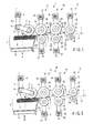
- FIG. 1 shows a schematic construction of a paper sheet separation and transfer apparatus 1 (hereinafter, simply referred to as a separation and transfer apparatus 1) according to the present invention.
- the separation and transfer apparatus 1 has a housing 2 which contains a plurality of stacked paper sheets P.
- a take-out roller 3 is provided at the position contacting a paper sheet P1 at one end of the stack of paper sheets P contained in the housing 2.
- Each roller shown in FIG. 1 has two rollers separated from each other in the axial direction.
- the take-out roller 3 is fixed to the rotary shaft through a one-way clutch 4, and the rotary shaft is fixed to the front end of a press arm 5.
- the rotary shaft of a press motor 6 is fixed to the base end of the press arm 5.
- the press arm 5 is swung by driving the press motor 6, and the take-out roller 3 is pressed to the paper sheet P1 at one end of the stack.
- the press arm 5 and press motor 6 function as a press mechanism of the present invention.
- a torque control motor is adopted for the press motor 6, and the pressing force of the take-out roller 3 to the paper sheet P1 can be changed optionally.
- the take-out roller 3 is freely rotatable in the arrow direction (the forward direction) in the drawing by the action of one-way clutch 4. Therefore, when transferring the paper sheet P in the arrow T direction (forward) in the drawing, the take-out roller 3 rotates together with the paper sheet P, and does not generate a reverse force disturbing the transfer of the paper sheet P, that is, a force along the tangential direction of the take-out roller (hereinafter, simply referred to as a tangential force).
- a take-out motor 9 is connected to the rotary shaft of the take-out roller 3 through a plurality of pulleys 7 and timing belts 8. Namely, by driving the take-out motor 9, the take-out roller 3 is rotated in the arrow direction in the drawing.
- a position control motor is adopted for the take-out motor 9, and the rotation speed, direction and amount (angle) of the take-out roller 9 can be controlled optionally.
- a backup plate 10 is provided to move a plurality of paper sheets P in the stack by pressing a paper sheet P at the other end of the stack, and to supply a paper sheet P1 at one end of the stack to a predetermined take-out position.
- the backup plate 10 is urged in the stacking direction by an actuator described later.
- a guide member 11 is provided at the position adjacent to the housing 2, or the position opposite to the front end of the take-out direction of a plurality of paper sheets P.
- the guide member 11 is bent toward the nip of a first separation unit described later, and functions to guide the front end of each paper P in the transfer direction to the nip.
- a first separation unit 13, a second separation unit 14 and a pull-out unit 15 are sequentially arranged close to each other along the transfer direction T.
- the first separation unit 13 has a first feed roller 16 which contacts the paper sheet P taken out onto the transfer path 12 and rotates forward along the transfer direction T, and a first separation roller 17 which is arranged opposite to the first feed roller 16 through the transfer path 12.
- the first separation roller 17 is pressed by a predetermined pressure to the first feed roller 16 in the state that no paper sheet P exists on the transfer path 12.
- the first feed roller 16 is arranged on the same side as the take-out roller 3 against the transfer path 12, that is, the upper side of the transfer path 12 in the drawing.
- the first feed roller 16 is attached to the rotary shaft through a one-way clutch 18. Therefore, when the paper sheet P is transferred in the arrow T direction along the transfer path 12, the first feed roller 16 rotates freely forward together with the paper sheet P, and does not generate a force (a tangential force) in the direction of disturbing the transfer of the paper sheet P.
- a first feed motor 21 is connected to the rotary shaft of the first feed roller 16 through a plurality of pulleys 19 and timing belts 20. Namely, by driving the first feed motor 21, the first feed roller 16 is rotated.
- a position control motor is adopted for the first feed motor 21, and the rotation speed, direction and amount (angle) of the first feed roller 16 can be controlled optionally.
- a first separation motor 24 is connected through a plurality of pulleys 22 and timing belts 23.
- the first separation motor 24 gives the first separation roller 17 a force in the direction to rotate the first separation roller 17 in the arrow direction in the drawing (the reverse direction).
- a torque control motor is adopted for the first separation motor 24, and a reverse separating force given by the first separation motor 24 to the first separation roller 17, that is, a separating force given by the first separation roller 17 to the paper sheet P in the tangential direction (hereinafter, sometimes referred to as a separation tangential force) can be changed optionally.
- a separation force given by the first separation motor 24 to the first separation roller 17 is set to the degree that the first separation roller 17 rotates forward together with the first feed roller 16, in the state that there is no paper sheet P to transfer on the transfer path 12, or the state that one paper sheet P is transferred.
- the first separation motor 24 tries to rotate the first separation roller 17 in the reverse direction, when no paper sheet P exists in the nip 13a in the space to the first feed roller 16, or when one paper sheet P exists, the first separation roller 17 is rotated forward.
- the first separation roller 17 gives a separating force (a separating tangential force) reverse to the direction T to the second and subsequent paper sheets P taken out together with the first paper sheet P1 in being overlapped therewith, and the second and subsequent paper sheets P are separated from the first paper sheet P1.
- the first separation roller 17 rotates together with the first paper sheet P1, and the first paper sheet P1 passes through the first separation unit 13.
- the second separation unit 14 provided on the downstream side of the first separation unit 13 along the paper sheet transfer direction T has the same structure as the first separation unit 13.
- the same reference numerals are given to the components having the similar functions, and detailed explanation will be omitted.
- different reference numerals are given to specific components.
- the second separation unit 14 has a second feed roller 25 driven and rotated by a second feed motor 27, and a second separation roller 26 given a separation force by a second separation motor 28.
- a position control motor is adopted for the second feed roller 27, and a torque control motor is adopted for the second separation motor 28.
- the second separation unit 14 functions to separate a plurality of paper sheets which are fed overlapped without being separated by the first separation unit 13.
- the pull-out unit 15 provided on the downstream side of the second separation unit 14 along the transfer direction T has a pull-out roller 29 and a pinch roller 30.
- the pull-out roller 29 is provided on the same side as the take-out roller 3 against the transfer path 12 (the upper side in the drawing).
- the pinch roller 30 is pressed by a predetermined pressure to the pull-out roller 29 through the transfer path 12.
- a pull-out motor 33 is connected to the rotary shaft of the pull-out roller 29 through a plurality of pulleys 31 and timing belts 32. Namely, by driving the pull-out motor 33, the pull-out roller 29 is rotated in the arrow direction in the drawing.
- a position control motor is adopted for the pull-out motor 33, and the rotation speed and amount (angle) of the pull-out roller 29 can be controlled optionally.
- a first sensor 34 (a first detector) and a second sensor 35 (a second detector) are provided on the transfer path 12.
- Each sensor 34 and 35 has a light emitting part and a light receiving part, detects the passage of the paper sheet P by the fact that the paper sheet P interrupts the light from the light emitting part to the light receiving part.
- the first sensor 34 is provided at the position where the light crosses the transfer path 12 between the nip 13a located between the first feed roller 16 and first separation roller 17 (hereinafter, called the nip 13a of the first separation unit 13) and a nip 14a located between the second feed roller 25 and second separation roller 26 (hereinafter, called the nip 14a of the second separation unit 14).
- the second sensor 35 is provided at the position where the light crosses the transfer path 12 between the nip 14a of the second separation unit 14 and a nip 15a located between the pull-out roller 29 and pinch roller 30 (hereinafter, called the nip 15a of the pull-out unit 15).
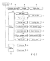
- FIG. 2 shows a block diagram of a control system which controls the operation of the separation and transfer apparatus 1 with the above structure.
- the separation and transfer apparatus 1 has a control unit 40 which controls the apparatus.
- the control unit 40 is connected with a mechanism controller 41, a motor controller 42 and a drive amplifier 43.
- the mechanism controller 41 is connected with an actuator 44 of the aforementioned backup plate 10.
- the motor controller 42 is connected with the press motor 6 which presses the take-out roller 3 to the paper sheet P1, the take-out motor 9 which rotates the take-out roller 3, a first feed motor 21 which rotates the first feed roller 16, a first separation motor 24 which gives the first separation roller 17 a reverse separation force, the second feed motor 27 which rotates the second feed roller 25, the second separation motor 28 which gives the second separation roller 26 a reverse separation force, and a pull-out motor 33 which rotates the pull-out roller 29.
- the drive amplifier 43 is connected with the aforementioned first sensor 34 and second sensor 35. Thus, the output signals from the sensors 34 and 35 are sent to the control unit 40.
- the control unit 40 controls the motor controller 42, drives the press motor 6, first feed motor 21, first separation motor 24, second feed motor 27, second separation motor 28 and pull-out motor 33, presses the take-out roller 3 to the paper sheet P1 at one end of the stack by a predetermined pressure, rotates forward the first feed roller 16, second feed roller 25 and pull-out roller 29 at a predetermined speed, and gives a predetermined separation torque to the first separation roller 17 and second separation roller 26 (Step 1).
- the first separation roller 17 rotates together with the first feed roller 16, and the second separation roller 26 rotates together with the second feed roller 25.
- control unit 40 controls the motor controller 42, drives the take-out motor 9 and rotates the take-out roller 3 forward at a predetermined speed, and takes out the paper sheet P1 at one end of the stack contacted and rotated by the take-out roller 3 onto the transfer path 12 (Step 2).
- the second and subsequent paper sheets may be taken out overlapped together with the first paper sheet P1 onto the transfer path 12.
- the motor controller 42 controls the rotation speeds of the motors 9, 21, 27 and 33, so that the peripheral speeds of the take-out roller 3, first feed roller 16, second feed roller 25 and pull-out roller 29 become V1, V2, V3 and V4, respectively.
- the motor controller 42 controls the rotation speeds of the rollers 3, 16, 25 and 29, so that the peripheral speeds V1, V2, V3 and V4 of the rollers satisfy the following expression: V ⁇ 1 ⁇ V ⁇ 2 ⁇ V ⁇ 3 ⁇ V ⁇ 4
- Step 3 When a certain time passes after detecting that the front end in the transfer direction of the paper sheet P1 taken out onto the transfer path 12 in step 2 has reached the first sensor 34 by passing through the nip 13a of the first separation unit 13 (Step 3; YES), the control unit 40 decelerates the take-out motor 9 and first feed motor 21, and decelerates the peripheral speeds of the take-out roller 3 and first feed roller 16 (Step 4). After the deceleration, the peripheral speeds V1' and V2' of the take-out roller 3 and feed roller 16 satisfy the following expression: V ⁇ 1 ⁇ ⁇ ⁇ V ⁇ 2 ⁇ ⁇ ⁇ V ⁇ 2
- the above certain time is the time from the arrival of the front end in the transfer direction of the paper sheet P1 at the first sensor 34 to the arrival at the nip 14a of the second separation unit 14, that is, the time determined by the peripheral speed of the first feed roller 16 and the distance from the position where the first sensor 34 crosses the transfer path 12 to the nip 14a of the second separation unit 14.
- the control unit 40 decelerates the take-out motor 9 and first feed motor 21 at the timing that the front end of the paper sheet P1 in the transfer direction reaches the nip 14a of the second separation unit 14.
- decelerate mentioned here and the term “decelerate” described in the Claims indicate the control to decelerate the roller rotating forward, and include all states from stop of the roller after deceleration to start of rotation in the reverse direction.
- control unit 40 detects that the rear end of the paper sheet P1 in the transfer direction passes through the first sensor 34 (Step 5; YES), and accelerates the take-out motor 9 and first feed motor 21 to return the peripheral speeds of the take-out roller 3 and first feed roller 16 to V1 and V2, respectively (Step 6). Then, the control unit 40 repeats the control of steps 2 to 6 until all paper sheets P contained in the housing 2 are taken out (Step 7: NO).
- control unit 40 monitors the time that the paper sheet P passes through the first sensor 34, while executing the control in the above steps 2 to 6, and when the passing time becomes longer than a certain predetermined value continuously over a predetermined numbers of time, the control unit 40 judges that there is a possibility that the overlapped feed of the paper sheet P occurs frequently exceeding the separating capacity in the first separation unit 13, and controls the press motor 6 to decrease the pressing force of the take-out roller 3 to the paper sheet P.
- the peripheral speeds of the take-out roller 3 and first feed roller 16 are "decelerated” at the time when the front end in the transfer direction of the paper sheet P1 taken out onto the transfer path 12 reaches the nip 14a of the second separation unit 14, and if there is second and subsequent paper sheets taken out together with the paper sheet P1, it is possible to prevent a defect of causing a wrinkle in the paper sheet P on and after the second sheet during the separating operation in the second separation unit 14.
- the peripheral speed of the first feed roller 16 which feeds forward the rear end of the second paper sheet P2 can be delayed at least, decreasing the possibility of buckling the second paper sheet P2 between the nips 13a and 14a.
- the term “decelerate” mentioned here includes “stop” and “reverse”, and for example, when the paper sheet P is a relatively flimsy bill, it is possible to prevent substantially a defect of causing a wrinkle in the second paper sheet P2 by "stopping" the take-out roller 3 and “reversing" the first feed roller 16 to meet the peripheral speed of the second separation roller 26.
- FIG. 4 is a flowchart showing a second operation example, in which the outputs of the first and second sensors 34 and 35 are monitored, the output signals of two sensors 34 and 35 are ored, and two rollers 3 and 16 are "decelerated".
- This second operation example is the same as the aforementioned first operation example except that the processing of step 5 is different.
- the control unit 40 monitors the output of the first sensor 34 and detects that the rear end of the first paper sheet P1 in the transfer direction passes, and monitors the output of the second sensor 35 and detects that the rear end of the first paper sheet P1 in the transfer direction passes.
- the control unit 40 return the peripheral speeds of the rollers 3 and 16.
- the control unit 40 "decelerates" continuously two rollers 3 and 16 until the rear end of the second paper sheet P2 in the transfer direction passes through the first sensor 34 in the first operation example, but in the second operation example, the peripheral speeds of the rollers 3 and 16 can be returned to the original speed at the time when the second sensor 35 detects the passage of the rear end of the first paper sheet P1 in the transfer direction. Namely, in this case, the time of "decelerating" the two rollers 3 and 16 can be reduced by adopting the second operation example.
- FIG. 5 shows a schematic construction of a separation and transfer apparatus 50 according to a second embodiment of the present invention.
- the first and second separation motors 24 and 28 contain encoders 51 and 52 (state detection unit), respectively.
- the separation and transfer apparatus 50 has the same structure as the aforementioned separation and transfer apparatus 1 except that the encoders 51 and 52 are used instead of the first and second sensors 34 and 35.
- the same reference numerals are given to the components having the same functions as in the separation and transfer apparatus 1, and detailed explanation of these components will be omitted.
- the encoder 51 contained in the first separation motor 24 detects the rotation speed of the first separation roller 17, and the encoder 52 contained in the second separation motor 28 detects the rotation speed of the second separation roller 26.
- the output ends of two encoders 51 and 52 are connected to the control unit 40. In other words, in this embodiment, the control unit 40 always monitors the rotation speeds of the first and second separation rollers 17 and 26 through the encoders 51 and 52.
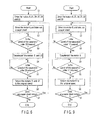
- FIG. 6 shows a flowchart for explaining a third operation example of the separation and transfer apparatus 50 with the above structure.
- This third operation example is basically the same as the first operation example except that the state of the paper sheet P is detected by the encoder 52.
- the control unit 40 monitors the output of the encoder 52 contained in the second separation motor 28 (Step 3), regards the drop of the rotation speed of the second separation roller 26 as a trigger (Step 3; YES), "decelerates” the take-out motor 9 and first feed motor 21, and “decelerates” the peripheral speeds of the take-out roller 3 and first feed roller 16 (Step 4).
- the term “decelerate” mentioned here includes “stop” and "reverse” as in the first embodiment.
- FIG. 7 shows changes with time of the rotation speed of the second separation roller 26 in the state rotated together with the second feed roller 25.
- the rotation speed of the second separation roller 26 is changed with time as shown in FIG. 8 . Namely, by monitoring the changes in the rotation speed of the second separation roller 26 through the encoder 52, it is possible to detect the state of the paper sheet P passing through the nip 14a of the second separation unit 14.
- Step 5 the control unit 40 regards the return of the rotation speed of the second separation roller 26 to the original speed (the arrow A in FIG. 8 ) as a trigger (Step 5; YES), judges that the first and second paper sheets P1 and P2 are separated, and accelerates the take-out motor 9 and first feed motor 21 so as to return the peripheral speeds of the take-out roller 3 and first feed roller 16 to V1 and V2, respectively (Step 6).
- the control unit 40 repeats the controls of steps 2 to 6 until all paper sheets P contained in the housing 2 are taken out (Step 7; NO).
- Step 3 When the rotation speed of the second separation roller 26 is lowered (Step 3; YES), the control unit 40 controls the first separation motor 24 to reduce the separation force given to the first separation roller 17. Namely, when the rotation speed of the second separation roller 26 is lowered as described above, the separation of the paper sheet P2 in the second separation unit 14 can be judged, and the separating operation in the first separation unit 13 becomes basically unnecessary.
- Step 3 when the rotation speed of the second separation roller 26 is lowered (Step 3; YES), the control unit 40 controls the press motor 6 to decrease the pressing force of the take-out roller 3 on the paper sheet P2.
- the forward force (tangential force) given to the separated paper sheet P2 can be decreased further, and the paper sheet P2 can be easily returned in the reverse direction.
- the control unit 40 regards the return of the rotation speed of the second separation roller 26 to the original speed as a trigger (Step 5; YES), judges that the separating operation is finished, returns the separation force given to the first separation roller 17 to the original value, and returns the pressing force of the take-out roller 3 to the paper sheet P to the original value.
- the separation and transfer unit 50 By operating the separation and transfer unit 50 according to the third operation example as explained above, the same effect as the first operation example can be obtained, and the state of the paper sheet P in the second separation unit 14 can be grasped more exactly, enabling more reliable separation and transfer.
- FIG. 9 is a flowchart showing a fourth operation example for preventing a buckle of the paper sheet P between the take-out roller 3 and nip 13a.
- the control unit 40 regards the drop of the rotation speed of the first separation roller 17 of the first separation unit 13 as a trigger (Step 3; YES), and controls the take-out motor 9 to "decelerate” the take-out roller 3 (Step 4).
- the term “deceleration” includes "stop” and "reverse”.
- the control unit 40 regards the return of the rotation speed of the first separation roller 17 to the original speed as a trigger after the end of the separating operation in the first separation unit 13 (Step 5; YES), and controls the take-out motor 9 to return the peripheral speed of the take-out roller 3 to the original speed (Step 6).
- the control unit 40 repeats the control of steps 2 to 6 until all paper sheets P contained in the housing 2 are taken out (Step 7; NO).
- Step 3 When the rotation speed of the second separation roller 26 is lowered (Step 3; YES), the control unit 40 controls the first separation motor 24 to reduce the separation force given to the first separation roller 17. Namely, when the rotation speed of the second separation roller 26 is lowered as described above, the separation of the paper sheet P2 in the second separation unit 14 can be judged, and the separating operation in the first separation unit 13 becomes basically unnecessary.
- the control unit 40 controls the first separation motor 24 and reduces the separating force given to the first separation roller 17. Namely, when the rotation speed of the first separation roller 17 is lowered, the rotation speed of the take-out roller 3 is decelerated, the pressing force of the take-out roller 3 is reduced, and the paper sheet can be easily separated. Therefore, the paper sheet is prevented from being moved back excessively, by reducing the separating force of the first separation roller 17.
- Step 3; YES When the rotation speed of the first separation roller 17 is lowered (Step 3; YES), the control unit 40 controls the press motor 6 so as to lower the pressing force of the take-out roller 3 on the paper sheet P, and makes it easy to return the paper sheet P2 in the reverse direction. Further, when the rotation speed of the first separation roller 17 is returned to the original speed (Step 5; YES), the control unit 40 controls the press motor 6 so as to return the pressing force of the take-out roller 3 to the original value.
- the take-out roller 3 is "decelerated” and the pressing force of the take-out roller 3 is lowered at the time when the separating operation is started in the first separation unit 13, the second paper sheet P2 taken out together with the first paper sheet P1 can be easily returned, and the buckling of the paper sheet P2 between the nip of the take-out roller 3 and nip 13a of the first separation unit 13 can be prevented.
- the overlapped state of paper sheet P is detected by using the sensors 34 and 35 or encoders 51 and 52.
- the invention is not to be limited to this.
- the overlapped state of paper sheet P may be detected by detecting the thickness of paper sheet P.
- the second embodiment uses the encoders 51 and 52 of the type incorporated in the separation motors 24 and 28, but an external encoder may be used. Or, it is permitted to use a tachogenerator for detecting the rotation speed.
- the stacking direction of the paper sheet P is shown vertical in FIG. 1 and FIG. 5 , but the horizontal direction is permitted, and the stacking is not to be limited to the gravity direction.
- the paper sheets P are taken out one by one onto the transfer path 12 by contacting and rotating the take-out roller 3 with the stacked paper sheets P, but a take-out belt can be used instead of the take-out roller 3. It is also permitted to use a pair of pull-out belts instead of the pull-out roller 29 and pinch roller 30.
Abstract
a take-out unit (3) which contacts a paper sheet at one end of a stack of a plurality of paper sheets, and takes out the paper sheet onto a transfer path;
a first separation unit (13) having a first feed roller (16) for feeding the paper sheet in a predetermined direction on the transfer path, and a first separation roller (17) which is pressed to the first feed roller through the transfer path, and separates second and following paper sheets taken out together with the first paper sheet by applying a separating force;
a second separation unit (14) having a second feed roller (25) for feeding the paper sheet in a predetermined direction on the transfer path, and a second separation roller (26) which is pressed to the second feed roller through the transfer path, and separates second and following paper sheets taken out together with the first paper sheet by applying a separating force;
a state detection unit (52) which detects the state that a plurality of paper sheets are present between the second feed roller (25) and second separation roller (26); and
a control unit (40) which causes the peripheral speed of the first feed roller (16) to decelerate, when the state detection unit (52) detects said state.
Description
- The present invention relates to a paper sheet separation and transfer apparatus which separates a plurality of stacked paper sheets such as postal matters, bills and plain-paper copies, one by one, and takes each sheet out onto a transfer path.
- As a conventional paper sheet separation and transfer apparatus, a separation and transfer apparatus having a separation unit to prevent overlapped paper sheet feeding has been known. (For example, refer to Jpn. Pat. Appln. KOKAI Publication No.
2003-81463 - The separation unit has a feed roller which contacts the paper sheet taken out onto the transfer path on the same side as the take-out roller and rotates forward, and a separation roller which is located opposite to the feed roller through the transfer path and separates second and subsequent paper sheets taken out together with the first sheet by giving them a reverse force (a tangential force).
- The transfer unit has a drive roller which accepts the transfer direction end of a paper sheet passed through a nip between the feed roller and separation roller, and rotates forward, thereby pulling out the paper sheet from the nip of the separation unit and feeding it, and a pinch roller which is arranged opposite to the drive roller through the transfer path.
- In the separation and transfer apparatus with the above structure, when stacked paper sheets are taken out onto the transfer path, the take-out roller is rotated first, and a paper sheet at one end of a stack is taken out onto the transfer path. In this case, by the friction between paper sheets, second and subsequent paper sheets may be taken out together with the first paper sheet. The taken-out second and subsequent paper sheets are separated by the separation unit, and transferred to a processing unit in a later stage through the transfer path.
- The separation unit feeds forward the preceding first paper sheet by the feed roller, and rotates the separation roller in the reverse direction contacting the second and subsequent sheets overlapped with the first sheet, and separates these second and subsequent paper sheets by pushing them in the reverse direction.
- However, in the above conventional unit, if the take-out roller takes out two paper sheets with different size and thickness, overlapped paper sheets may not by completely separated by one separation unit.
- It is an object of the present invention to provide a paper sheet separation and transfer apparatus which can separate and transfer stacked paper sheets with certainty.
- In order to achieve the above object, there is provided a paper sheet separation and transfer apparatus in accordance with
claim 1. - Further embodiments are described in the dependent claims.
- This summary of the invention does not necessarily describe all necessary features so that the invention may also be a sub-combination of these described features.
- The invention can be more fully understood from the following detailed description when taken in conjunction with the accompanying drawings, in which:
-
- FIG. 1
- is a schematic illustration showing a separation and transfer apparatus according to a first embodiment of the present invention;
- FIG. 2
- is a block diagram of a control system which controls operation of the separation and transfer apparatus of
FIG. 1 ; i - FIG. 3
- is a flowchart for explaining a first operation example of the separation and transfer apparatus of
FIG. 1 ; - FIG. 4
- is a flowchart for explaining a second operation example of the separation and transfer apparatus of
FIG. 1 ; - FIG. 5
- is a schematic illustration showing a separation and transfer apparatus according to a second embodiment of the present invention;
- FIG. 6
- is a flowchart for explaining a third operation example of the separation and transfer apparatus of
FIG. 5 ; - FIG. 7
- is a graph showing changes with time of the rotation speed of a separation roller in the state that the separation roller is co-rotated;
- FIG. 8
- is a graph showing changes with time of the rotation speed of a separation roller during the separating operation; and
- FIG. 9
- is a flowchart for explaining a fourth operation example of the separation and transfer apparatus of
FIG. 5 . - Hereinafter, detailed explanation will be given on embodiments of the present invention with reference to the accompanying drawings.
-
FIG. 1 shows a schematic construction of a paper sheet separation and transfer apparatus 1 (hereinafter, simply referred to as a separation and transfer apparatus 1) according to the present invention. - The separation and
transfer apparatus 1 has ahousing 2 which contains a plurality of stacked paper sheets P. A take-out roller 3 is provided at the position contacting a paper sheet P1 at one end of the stack of paper sheets P contained in thehousing 2. Each roller shown inFIG. 1 has two rollers separated from each other in the axial direction. - The take-
out roller 3 is fixed to the rotary shaft through a one-way clutch 4, and the rotary shaft is fixed to the front end of apress arm 5. The rotary shaft of apress motor 6 is fixed to the base end of thepress arm 5. Thus, thepress arm 5 is swung by driving thepress motor 6, and the take-out roller 3 is pressed to the paper sheet P1 at one end of the stack. Thepress arm 5 and pressmotor 6 function as a press mechanism of the present invention. - In this embodiment, a torque control motor is adopted for the
press motor 6, and the pressing force of the take-out roller 3 to the paper sheet P1 can be changed optionally. The take-out roller 3 is freely rotatable in the arrow direction (the forward direction) in the drawing by the action of one-way clutch 4. Therefore, when transferring the paper sheet P in the arrow T direction (forward) in the drawing, the take-out roller 3 rotates together with the paper sheet P, and does not generate a reverse force disturbing the transfer of the paper sheet P, that is, a force along the tangential direction of the take-out roller (hereinafter, simply referred to as a tangential force). - A take-
out motor 9 is connected to the rotary shaft of the take-out roller 3 through a plurality ofpulleys 7 andtiming belts 8. Namely, by driving the take-outmotor 9, the take-out roller 3 is rotated in the arrow direction in the drawing. In this embodiment, a position control motor is adopted for the take-outmotor 9, and the rotation speed, direction and amount (angle) of the take-out roller 9 can be controlled optionally. - On the opposite side of the
housing 2 against the take-out roller 3, abackup plate 10 is provided to move a plurality of paper sheets P in the stack by pressing a paper sheet P at the other end of the stack, and to supply a paper sheet P1 at one end of the stack to a predetermined take-out position. Thebackup plate 10 is urged in the stacking direction by an actuator described later. - A
guide member 11 is provided at the position adjacent to thehousing 2, or the position opposite to the front end of the take-out direction of a plurality of paper sheets P. Theguide member 11 is bent toward the nip of a first separation unit described later, and functions to guide the front end of each paper P in the transfer direction to the nip. - When the take-
out roller 3 pressed by thepress motor 6 to the paper sheet P at one end of the stack is rotated forward by the take-outmotor 9, the paper sheet P1 supplied by thebackup plate 10 to the predetermined take-out position is taken out onto atransfer path 12. In this time, by the friction between the paper sheets P, second and subsequent sheets may be taken out together with the first paper sheet P1. - On the
transfer path 12 of the downstream side of the take-out roller 3, afirst separation unit 13, asecond separation unit 14 and a pull-outunit 15 are sequentially arranged close to each other along the transfer direction T. - The
first separation unit 13 has afirst feed roller 16 which contacts the paper sheet P taken out onto thetransfer path 12 and rotates forward along the transfer direction T, and afirst separation roller 17 which is arranged opposite to thefirst feed roller 16 through thetransfer path 12. Thefirst separation roller 17 is pressed by a predetermined pressure to thefirst feed roller 16 in the state that no paper sheet P exists on thetransfer path 12. - The
first feed roller 16 is arranged on the same side as the take-out roller 3 against thetransfer path 12, that is, the upper side of thetransfer path 12 in the drawing. Thefirst feed roller 16 is attached to the rotary shaft through a one-way clutch 18. Therefore, when the paper sheet P is transferred in the arrow T direction along thetransfer path 12, thefirst feed roller 16 rotates freely forward together with the paper sheet P, and does not generate a force (a tangential force) in the direction of disturbing the transfer of the paper sheet P. - A
first feed motor 21 is connected to the rotary shaft of thefirst feed roller 16 through a plurality ofpulleys 19 andtiming belts 20. Namely, by driving thefirst feed motor 21, thefirst feed roller 16 is rotated. In this embodiment, a position control motor is adopted for thefirst feed motor 21, and the rotation speed, direction and amount (angle) of thefirst feed roller 16 can be controlled optionally. - To the rotary shaft of the
first separation roller 17, afirst separation motor 24 is connected through a plurality ofpulleys 22 andtiming belts 23. Thefirst separation motor 24 gives the first separation roller 17 a force in the direction to rotate thefirst separation roller 17 in the arrow direction in the drawing (the reverse direction). In this embodiment, a torque control motor is adopted for thefirst separation motor 24, and a reverse separating force given by thefirst separation motor 24 to thefirst separation roller 17, that is, a separating force given by thefirst separation roller 17 to the paper sheet P in the tangential direction (hereinafter, sometimes referred to as a separation tangential force) can be changed optionally. - However, a separation force given by the
first separation motor 24 to thefirst separation roller 17 is set to the degree that thefirst separation roller 17 rotates forward together with thefirst feed roller 16, in the state that there is no paper sheet P to transfer on thetransfer path 12, or the state that one paper sheet P is transferred. In other words, even if thefirst separation motor 24 tries to rotate thefirst separation roller 17 in the reverse direction, when no paper sheet P exists in the nip 13a in the space to thefirst feed roller 16, or when one paper sheet P exists, thefirst separation roller 17 is rotated forward. - When a plurality of paper sheets P is fed overlapped to the
first separation unit 13, the preceding first paper sheet P1 is fed in the arrow T direction by thefirst feed roller 16 around which the first paper sheet P1 is rotated forward, thefirst separation roller 17 gives a separating force (a separating tangential force) reverse to the direction T to the second and subsequent paper sheets P taken out together with the first paper sheet P1 in being overlapped therewith, and the second and subsequent paper sheets P are separated from the first paper sheet P1. Of course, if the second and subsequent paper sheets P are not taken out together when the first paper sheet P1 is taken out, thefirst separation roller 17 rotates together with the first paper sheet P1, and the first paper sheet P1 passes through thefirst separation unit 13. - The
second separation unit 14 provided on the downstream side of thefirst separation unit 13 along the paper sheet transfer direction T has the same structure as thefirst separation unit 13. Thus, the same reference numerals are given to the components having the similar functions, and detailed explanation will be omitted. However, to simplify the explanation, different reference numerals are given to specific components. Namely, thesecond separation unit 14 has asecond feed roller 25 driven and rotated by asecond feed motor 27, and asecond separation roller 26 given a separation force by asecond separation motor 28. A position control motor is adopted for thesecond feed roller 27, and a torque control motor is adopted for thesecond separation motor 28. Thesecond separation unit 14 functions to separate a plurality of paper sheets which are fed overlapped without being separated by thefirst separation unit 13. - The pull-out
unit 15 provided on the downstream side of thesecond separation unit 14 along the transfer direction T has a pull-outroller 29 and apinch roller 30. The pull-outroller 29 is provided on the same side as the take-outroller 3 against the transfer path 12 (the upper side in the drawing). Thepinch roller 30 is pressed by a predetermined pressure to the pull-outroller 29 through thetransfer path 12. - A pull-out
motor 33 is connected to the rotary shaft of the pull-outroller 29 through a plurality ofpulleys 31 andtiming belts 32. Namely, by driving the pull-outmotor 33, the pull-outroller 29 is rotated in the arrow direction in the drawing. In this embodiment, a position control motor is adopted for the pull-outmotor 33, and the rotation speed and amount (angle) of the pull-outroller 29 can be controlled optionally. - When the front end in the transfer direction of the paper sheet P passed through the
second separation unit 14 is fed to the nip between the pull-outroller 29 andpinch roller 30, the paper sheet P is pulled out from thesecond separation unit 14 by the pull-outunit 15. The paper sheet P pulled out by the pull-outunit 15 is transferred to a not-shown processing unit in the later stage and processed there. - On the
transfer path 12, a first sensor 34 (a first detector) and a second sensor 35 (a second detector) are provided. Eachsensor - The
first sensor 34 is provided at the position where the light crosses thetransfer path 12 between the nip 13a located between thefirst feed roller 16 and first separation roller 17 (hereinafter, called the nip 13a of the first separation unit 13) and a nip 14a located between thesecond feed roller 25 and second separation roller 26 (hereinafter, called thenip 14a of the second separation unit 14). Thesecond sensor 35 is provided at the position where the light crosses thetransfer path 12 between the nip 14a of thesecond separation unit 14 and a nip 15a located between the pull-outroller 29 and pinch roller 30 (hereinafter, called thenip 15a of the pull-out unit 15). -
FIG. 2 shows a block diagram of a control system which controls the operation of the separation andtransfer apparatus 1 with the above structure. - The separation and
transfer apparatus 1 has acontrol unit 40 which controls the apparatus. Thecontrol unit 40 is connected with amechanism controller 41, amotor controller 42 and adrive amplifier 43. Themechanism controller 41 is connected with anactuator 44 of theaforementioned backup plate 10. - The
motor controller 42 is connected with thepress motor 6 which presses the take-outroller 3 to the paper sheet P1, the take-outmotor 9 which rotates the take-outroller 3, afirst feed motor 21 which rotates thefirst feed roller 16, afirst separation motor 24 which gives the first separation roller 17 a reverse separation force, thesecond feed motor 27 which rotates thesecond feed roller 25, thesecond separation motor 28 which gives the second separation roller 26 a reverse separation force, and a pull-outmotor 33 which rotates the pull-outroller 29. - The
drive amplifier 43 is connected with the aforementionedfirst sensor 34 andsecond sensor 35. Thus, the output signals from thesensors control unit 40. - Next, a first operation example of the separation and
transfer apparatus 1 with the above-mentioned structure will be explained with reference to the flowchart ofFIG. 3 . - First, the
control unit 40 controls themotor controller 42, drives thepress motor 6,first feed motor 21,first separation motor 24,second feed motor 27,second separation motor 28 and pull-outmotor 33, presses the take-outroller 3 to the paper sheet P1 at one end of the stack by a predetermined pressure, rotates forward thefirst feed roller 16,second feed roller 25 and pull-outroller 29 at a predetermined speed, and gives a predetermined separation torque to thefirst separation roller 17 and second separation roller 26 (Step 1). In this state, as the paper sheet P is not transferred through thetransfer path 12, thefirst separation roller 17 rotates together with thefirst feed roller 16, and thesecond separation roller 26 rotates together with thesecond feed roller 25. - In this state, the
control unit 40 controls themotor controller 42, drives the take-outmotor 9 and rotates the take-outroller 3 forward at a predetermined speed, and takes out the paper sheet P1 at one end of the stack contacted and rotated by the take-outroller 3 onto the transfer path 12 (Step 2). In this case, the second and subsequent paper sheets may be taken out overlapped together with the first paper sheet P1 onto thetransfer path 12. - In
steps motor controller 42 controls the rotation speeds of themotors roller 3,first feed roller 16,second feed roller 25 and pull-outroller 29 become V1, V2, V3 and V4, respectively. Here, themotor controller 42 controls the rotation speeds of therollers 
- As explained above, by making the peripheral speeds of the
rollers transfer path 12. Further, by making the speeds of the rollers different to satisfy the above expression, a buckle in the paper sheet P on the way of transfer can be prevented. However, if the peripheral speed difference is too large, the transfer gap will become unnecessarily large. Therefore, it is necessary to adjust the speed difference to an appropriate value. - When a certain time passes after detecting that the front end in the transfer direction of the paper sheet P1 taken out onto the
transfer path 12 instep 2 has reached thefirst sensor 34 by passing through the nip 13a of the first separation unit 13 (Step 3; YES), thecontrol unit 40 decelerates the take-outmotor 9 andfirst feed motor 21, and decelerates the peripheral speeds of the take-outroller 3 and first feed roller 16 (Step 4). After the deceleration, the peripheral speeds V1' and V2' of the take-outroller 3 and feedroller 16 satisfy the following expression:
- The above certain time is the time from the arrival of the front end in the transfer direction of the paper sheet P1 at the
first sensor 34 to the arrival at the nip 14a of thesecond separation unit 14, that is, the time determined by the peripheral speed of thefirst feed roller 16 and the distance from the position where thefirst sensor 34 crosses thetransfer path 12 to the nip 14a of thesecond separation unit 14. In other words, instep 4, thecontrol unit 40 decelerates the take-outmotor 9 andfirst feed motor 21 at the timing that the front end of the paper sheet P1 in the transfer direction reaches the nip 14a of thesecond separation unit 14. The term "decelerate" mentioned here and the term "decelerate" described in the Claims indicate the control to decelerate the roller rotating forward, and include all states from stop of the roller after deceleration to start of rotation in the reverse direction. - Thereafter, the
control unit 40 detects that the rear end of the paper sheet P1 in the transfer direction passes through the first sensor 34 (Step 5; YES), and accelerates the take-outmotor 9 andfirst feed motor 21 to return the peripheral speeds of the take-outroller 3 andfirst feed roller 16 to V1 and V2, respectively (Step 6). Then, thecontrol unit 40 repeats the control ofsteps 2 to 6 until all paper sheets P contained in thehousing 2 are taken out (Step 7: NO). - Further, the
control unit 40 monitors the time that the paper sheet P passes through thefirst sensor 34, while executing the control in theabove steps 2 to 6, and when the passing time becomes longer than a certain predetermined value continuously over a predetermined numbers of time, thecontrol unit 40 judges that there is a possibility that the overlapped feed of the paper sheet P occurs frequently exceeding the separating capacity in thefirst separation unit 13, and controls thepress motor 6 to decrease the pressing force of the take-outroller 3 to the paper sheet P. - As describe above, in the first operation example, the peripheral speeds of the take-out
roller 3 andfirst feed roller 16 are "decelerated" at the time when the front end in the transfer direction of the paper sheet P1 taken out onto thetransfer path 12 reaches the nip 14a of thesecond separation unit 14, and if there is second and subsequent paper sheets taken out together with the paper sheet P1, it is possible to prevent a defect of causing a wrinkle in the paper sheet P on and after the second sheet during the separating operation in thesecond separation unit 14. - Conversely, when the "decelerate" control explained in the first operation example is not adopted, for example, in the state that the first paper sheet P1 and second paper sheet P2 are being separated in the
second separation unit 14 and that the rear end of the paper sheet P1 in the transfer direction passes through the nip 13a of thefirst separation unit 13, the front end of the second paper sheet P2 is returned to the reverse direction by thesecond separation roller 26 of thesecond separation unit 14, and the rear end of the second paper sheet P2 is fed forward by thefirst feed roller 16 of thefirst separation unit 13, and the second paper sheet P2 buckles and causes a wrinkle between twonips 13a and 14a. - Namely, in this case, if the above mentioned "decelerate" control of the present invention is adopted, the peripheral speed of the
first feed roller 16 which feeds forward the rear end of the second paper sheet P2 can be delayed at least, decreasing the possibility of buckling the second paper sheet P2 between thenips 13a and 14a. As described above, the term "decelerate" mentioned here includes "stop" and "reverse", and for example, when the paper sheet P is a relatively flimsy bill, it is possible to prevent substantially a defect of causing a wrinkle in the second paper sheet P2 by "stopping" the take-outroller 3 and "reversing" thefirst feed roller 16 to meet the peripheral speed of thesecond separation roller 26. - Namely, it is necessary to select appropriate degree of "deceleration" of the take-out
roller 3 andfirst feed roller 16 according to the physical characteristics of the paper sheet P, such as flexibility, material, thickness and hardness. For example, when separating and transferring relatively thick and hard paper sheets P such as postal matter, the above-mentioned buckling can be prevented simply by "decelerating" slightly the take-outroller 3 andfirst feed roller 16. The buckling problem may also be solved by decreasing the pressing force of the take-outroller 3 by thepress motor 6 instead of "decelerating" the take-outroller 3. - In the above-mentioned first operation example, explanation has been given of the case that two
rollers first sensor 34. However, the separation andtransfer apparatus 1 of this embodiment has twoseparation units -
FIG. 4 is a flowchart showing a second operation example, in which the outputs of the first andsecond sensors sensors rollers step 5 is different. - Namely, in the processing of step 5' different from the first operation example, the
control unit 40 monitors the output of thefirst sensor 34 and detects that the rear end of the first paper sheet P1 in the transfer direction passes, and monitors the output of thesecond sensor 35 and detects that the rear end of the first paper sheet P1 in the transfer direction passes. When one of the first andsecond sensors control unit 40 return the peripheral speeds of therollers - By the above operation of
the.control unit 40, for example, when the second paper sheet P2 is taken out together with the first paper sheet P1 and these two overlapped sheets are not separated by thefirst separation unit 13 but separated by thesecond separation unit 14, thecontrol unit 40 "decelerates" continuously tworollers first sensor 34 in the first operation example, but in the second operation example, the peripheral speeds of therollers second sensor 35 detects the passage of the rear end of the first paper sheet P1 in the transfer direction. Namely, in this case, the time of "decelerating" the tworollers - As described above, by adopting the second operation example, the same effect as that obtained when adopting the first operation example can be obtained, and the processing time can be reduced.
-
FIG. 5 shows a schematic construction of a separation andtransfer apparatus 50 according to a second embodiment of the present invention. In the separation andtransfer apparatus 50, the first andsecond separation motors encoders 51 and 52 (state detection unit), respectively. In other words, the separation andtransfer apparatus 50 has the same structure as the aforementioned separation andtransfer apparatus 1 except that theencoders second sensors transfer apparatus 1, and detailed explanation of these components will be omitted. - The
encoder 51 contained in thefirst separation motor 24 detects the rotation speed of thefirst separation roller 17, and theencoder 52 contained in thesecond separation motor 28 detects the rotation speed of thesecond separation roller 26. The output ends of twoencoders control unit 40. In other words, in this embodiment, thecontrol unit 40 always monitors the rotation speeds of the first andsecond separation rollers encoders -
FIG. 6 shows a flowchart for explaining a third operation example of the separation andtransfer apparatus 50 with the above structure. This third operation example is basically the same as the first operation example except that the state of the paper sheet P is detected by theencoder 52. - Namely, after rotating the take-out
roller 3 and taking out the first paper sheet P1 (Steps 1 and 2), thecontrol unit 40 monitors the output of theencoder 52 contained in the second separation motor 28 (Step 3), regards the drop of the rotation speed of thesecond separation roller 26 as a trigger (Step 3; YES), "decelerates" the take-outmotor 9 andfirst feed motor 21, and "decelerates" the peripheral speeds of the take-outroller 3 and first feed roller 16 (Step 4). The term "decelerate" mentioned here includes "stop" and "reverse" as in the first embodiment. - When no paper sheet P exists in the
nip 14a and when one paper sheet P exists in thenip 14a, thesecond separation roller 26 rotates together with thesecond feed roller 25 at the same speed.FIG. 7 shows changes with time of the rotation speed of thesecond separation roller 26 in the state rotated together with thesecond feed roller 25. On the other hand, when a plurality of overlapped paper sheets P passes through the nip 14a of thesecond separation unit 14, that is, when a plurality of paper sheets P is separated by thesecond separation unit 14, the rotation speed of thesecond separation roller 26 is changed with time as shown inFIG. 8 . Namely, by monitoring the changes in the rotation speed of thesecond separation roller 26 through theencoder 52, it is possible to detect the state of the paper sheet P passing through the nip 14a of thesecond separation unit 14. - After "decelerating" two
rollers step 4, thecontrol unit 40 regards the return of the rotation speed of thesecond separation roller 26 to the original speed (the arrow A inFIG. 8 ) as a trigger (Step 5; YES), judges that the first and second paper sheets P1 and P2 are separated, and accelerates the take-outmotor 9 andfirst feed motor 21 so as to return the peripheral speeds of the take-outroller 3 andfirst feed roller 16 to V1 and V2, respectively (Step 6). - The
control unit 40 repeats the controls ofsteps 2 to 6 until all paper sheets P contained in thehousing 2 are taken out (Step 7; NO). - When the rotation speed of the
second separation roller 26 is lowered (Step 3; YES), thecontrol unit 40 controls thefirst separation motor 24 to reduce the separation force given to thefirst separation roller 17. Namely, when the rotation speed of thesecond separation roller 26 is lowered as described above, the separation of the paper sheet P2 in thesecond separation unit 14 can be judged, and the separating operation in thefirst separation unit 13 becomes basically unnecessary. - Further, when the rotation speed of the
second separation roller 26 is lowered (Step 3; YES), thecontrol unit 40 controls thepress motor 6 to decrease the pressing force of the take-outroller 3 on the paper sheet P2. By this operation, the forward force (tangential force) given to the separated paper sheet P2 can be decreased further, and the paper sheet P2 can be easily returned in the reverse direction. - The
control unit 40 regards the return of the rotation speed of thesecond separation roller 26 to the original speed as a trigger (Step 5; YES), judges that the separating operation is finished, returns the separation force given to thefirst separation roller 17 to the original value, and returns the pressing force of the take-outroller 3 to the paper sheet P to the original value. - By operating the separation and
transfer unit 50 according to the third operation example as explained above, the same effect as the first operation example can be obtained, and the state of the paper sheet P in thesecond separation unit 14 can be grasped more exactly, enabling more reliable separation and transfer. - In the above third operation example, explanation has been given on a method of preventing a wrinkle caused by the buckling of the paper sheet P2 between the
nips 13a and 14a of the first andsecond separation units second separation unit 14. The paper sheep P may buckle between the position where the take-outroller 3 contacts and rotates with the paper sheet P, and the nip 13a of thefirst separation unit 13. -
FIG. 9 is a flowchart showing a fourth operation example for preventing a buckle of the paper sheet P between the take-outroller 3 and nip 13a. According to the drawing, after the first paper sheet P1 is taken out onto the transfer path 12 (Steps 1, 2), thecontrol unit 40 regards the drop of the rotation speed of thefirst separation roller 17 of thefirst separation unit 13 as a trigger (Step 3; YES), and controls the take-outmotor 9 to "decelerate" the take-out roller 3 (Step 4). The term "deceleration" includes "stop" and "reverse". - The
control unit 40 regards the return of the rotation speed of thefirst separation roller 17 to the original speed as a trigger after the end of the separating operation in the first separation unit 13 (Step 5; YES), and controls the take-outmotor 9 to return the peripheral speed of the take-outroller 3 to the original speed (Step 6). Thecontrol unit 40 repeats the control ofsteps 2 to 6 until all paper sheets P contained in thehousing 2 are taken out (Step 7; NO). - When the rotation speed of the
second separation roller 26 is lowered (Step 3; YES), thecontrol unit 40 controls thefirst separation motor 24 to reduce the separation force given to thefirst separation roller 17. Namely, when the rotation speed of thesecond separation roller 26 is lowered as described above, the separation of the paper sheet P2 in thesecond separation unit 14 can be judged, and the separating operation in thefirst separation unit 13 becomes basically unnecessary. - In addition, when the rotation speed of the
first separation roller 17 is lowered, thecontrol unit 40 controls thefirst separation motor 24 and reduces the separating force given to thefirst separation roller 17. Namely, when the rotation speed of thefirst separation roller 17 is lowered, the rotation speed of the take-outroller 3 is decelerated, the pressing force of the take-outroller 3 is reduced, and the paper sheet can be easily separated. Therefore, the paper sheet is prevented from being moved back excessively, by reducing the separating force of thefirst separation roller 17. - When the rotation speed of the
first separation roller 17 is lowered (Step 3; YES), thecontrol unit 40 controls thepress motor 6 so as to lower the pressing force of the take-outroller 3 on the paper sheet P, and makes it easy to return the paper sheet P2 in the reverse direction. Further, when the rotation speed of thefirst separation roller 17 is returned to the original speed (Step 5; YES), thecontrol unit 40 controls thepress motor 6 so as to return the pressing force of the take-outroller 3 to the original value. - As explained above, in the fourth operation example, since the take-out
roller 3 is "decelerated" and the pressing force of the take-outroller 3 is lowered at the time when the separating operation is started in thefirst separation unit 13, the second paper sheet P2 taken out together with the first paper sheet P1 can be easily returned, and the buckling of the paper sheet P2 between the nip of the take-outroller 3 and nip 13a of thefirst separation unit 13 can be prevented. - Additional advantages and modifications will readily occur to those skilled in the art. Therefore, the invention in its broader aspects is not limited to the specific details and representative embodiments shown and described herein. Accordingly, various modifications may be made without departing from the spirit or scope of the general inventive concept as defined by the appended claims and their equivalents.
- For example, in the above embodiment, explanation has been given of the case that the overlapped state of paper sheet P is detected by using the
sensors encoders encoders separation motors - Further, the stacking direction of the paper sheet P is shown vertical in
FIG. 1 and FIG. 5 , but the horizontal direction is permitted, and the stacking is not to be limited to the gravity direction. Further, in the above embodiment, the paper sheets P are taken out one by one onto thetransfer path 12 by contacting and rotating the take-outroller 3 with the stacked paper sheets P, but a take-out belt can be used instead of the take-outroller 3. It is also permitted to use a pair of pull-out belts instead of the pull-outroller 29 andpinch roller 30. - It is explicitly stated that all features disclosed in the description and/or the claims are intended to be disclosed separately and independently from each other for the purpose of original disclosure as well as for the purpose of restricting the claimed invention independent of the composition of the features in the embodiments and/or the claims. It is explicitly stated that all value ranges or indications of groups of entities disclose every possible intermediate value or intermediate entity for the purpose of original disclosure as well as for the purpose of restricting the claimed invention, in particular as limits of value ranges.
- The disclosure of the invention comprises the aspects laid down below, which are part of the description but not part of the claims in accordance with the decision J15/88 of the Board of Appeal.
- 1. A paper sheet separation and transfer apparatus characterized by comprising:
- a take-out roller (3) which rotates and contacts a paper sheet at one end of a stack of a plurality of paper sheets, and takes out the paper sheet onto a transfer path;
- a first separation unit (13) having a first feed roller (16) which contacts the paper sheet taken out onto the transfer path and rotates forward, and a first separation roller (17) which is pressed to the first feed roller through the transfer path, and separates second and following paper sheets taken out together with the first paper sheet by giving a reverse separating force;
- a second separation unit (14) having a second feed roller (25) which contacts the paper sheet passed through the first separation unit and rotates forward, and a second separation roller (26) which is pressed to the second feed roller through the transfer path, and separates second and following paper sheets taken out together with the first paper sheet by giving a reverse separating force;
- a first detector (34) which detects that a preceding paper sheet reaches the second separation unit; and
- a control unit (40) which decelerates the peripheral speed of the first feed roller, when the first detector detects that a preceding paper sheet reaches the second separation unit.
- 2. The paper sheet separation and transfer apparatus according to
aspect 1, characterized in that the control unit (40) returns the peripheral speed of the first feed roller (16) to the original speed, when the first detector (34) detects that the rear end of a paper sheet in the transfer direction passes through the second separation unit (14). - 3. The paper sheet separation and transfer apparatus according to
aspect 1, characterized by further comprising:- a second detector (36) which detects that a paper sheet passes along the transfer direction in the downstream side of the second separation unit (14), and
- wherein the control unit (40) returns the peripheral speed of the first feed roller (16) to the original speed, when the first detector (34) or second detector (35) detects that the rear end of a paper sheet passes in the transfer direction through the second separation unit (14).
- 4. The paper sheet separation and transfer apparatus according to
aspect 1, characterized in that the control unit (40) decelerates the peripheral speed of the take-out roller (3), when the first detector (34) detects that a preceding paper sheet reaches the second separation unit (14). - 5. The paper sheet separation and transfer apparatus according to
aspect 4, characterized in that the control unit (40) returns the peripheral speed of the take-out roller (3) to the original speed, when the first detector (34) detects that the rear end of a paper sheet passes in the transfer direction through the second separation unit (14). - 6. The paper sheet separation and transfer apparatus according to
aspect 1, characterized by further comprising a press mechanism (6) which presses the take-out roller (3) to a paper sheet, the control unit (40) controls the press mechanism (6) to lower the pressing force of the take-out roller (3), when the first detector (34) detects that a preceding paper sheet reaches the second separation unit (14). - 7. The paper sheet separation and transfer apparatus according to
aspect 6, the control unit (40) controls the press mechanism (6) to return the pressing force of the take-out roller (3) to the original force, when the first detector (34) detects that the rear end of a paper sheet passes in the transfer direction through the second separation unit (14). - 8. A paper sheet separation and transfer apparatus characterized by comprising:
- a take-out roller (3) which rotates and contacts a paper sheet at one end of a stack of a plurality of paper sheets, and takes out the paper sheet onto a transfer path;
- a first separation unit (13) having a first feed roller (16) which contacts the paper sheet taken out onto the transfer path and rotates forward, and a first separation roller (17) which is pressed to the first feed roller through the transfer path, and separates second and following paper sheets taken out together with the first paper sheet by giving a reverse separating force;
- a second separation unit (14) having a second feed roller (25) which contacts the paper sheet passed through the first separation unit (13) and rotates forward, and a second separation roller (26) which is pressed to the second feed roller through the transfer path, and separates second and following paper sheets taken out together with the first paper sheet by giving a reverse separating force;
- a state detection unit (52) which detects the state that a plurality of paper sheets exist between the second feed roller (25) and second separation roller (26); and
- a control unit (40) which decelerates the peripheral speed of the first feed roller (16), when the state detection unit (52) detects said state.
- 9. The paper sheet separation and transfer apparatus according to
aspect 8, characterized in that the control unit (40) stops the first feed roller (16), when the state detection unit (52) detects said state. - 10. The paper sheet separation and transfer apparatus according to
aspect 8, characterized in that the control unit (40) rotates the first feed roller (16) in the reverse direction, when the state detection unit (52) detects said state. - 11. The paper sheet separation and transfer apparatus according to
aspect 8, characterized in that the control unit (40) returns the peripheral speed of the first feed roller (16) to the original speed, when said state is reset. - 12. The paper sheet separation and transfer apparatus according to
aspect 8, characterized in that the control unit (40) decelerates the peripheral speed of the take-out roller (3), when the state detection unit (52) detects said state. - 13. The paper sheet separation and transfer apparatus according to
aspect 12, characterized in that the control unit (40) returns the peripheral speed of the take-out roller (3) to the original speed, when said state is reset. - 14. The paper sheet separation and transfer apparatus according to
aspect 8, characterized by further comprising a press mechanism (6) which presses the take-out roller (3) to a paper sheet, wherein the control unit (40) controls the press mechanism (6) to lower the pressing force of the take-out roller (3), when the state detection unit (52) detects said state. - 15. The paper sheet separation and transfer apparatus according to
aspect 14, characterized in that the control unit (40) controls the press mechanism (6) to return the pressing force of the take-out roller (3) to the original force, when said state is reset. - 16. The paper sheet separation and transfer apparatus according to
aspect 8, characterized in that the control unit (40) lowers the separating force of the first separation roller (17), when the state detection unit (52) detects said state. - 17. The paper sheet separation and transfer apparatus according to
aspect 16, characterized in that the control unit (40) returns the separating force of the first separation roller (17) to the original force, when said state is reset. - 18. The paper sheet separation and transfer apparatus according to
aspect 8, characterized in that the state detection unit (52) detects the rotation speed of the second separation roller (26), and detects said state based on the result of the detection. - 19. A paper sheet separation and transfer apparatus characterized by comprising:
- a take-out roller (13) which rotates and contacts a paper sheet at one end of a stack of a plurality of paper sheets, and takes out the paper sheet onto a transfer path;
- a first separation unit (13) having a first feed roller (16) which contacts the paper sheet taken out onto the transfer path and rotates forward, and a first separation roller (17) which is pressed to the first feed roller through the transfer path, and separates second and following paper sheets taken out together with the first paper sheet by giving a reverse separating force;
- a state detection unit (51) which detects the state that a plurality of paper sheets exist between the first feed roller (16) and first separation roller (17); and
- a control unit (40) which decelerates the peripheral speed of the take-out roller (3), when the state detection unit (51) detects said state.
- 20. The paper sheet separation and transfer apparatus according to
aspect 19, characterized in that the control unit (40) returns the peripheral speed of the take-out roller (3) to the original speed, when said state is reset. - 21. The paper sheet separation and transfer apparatus according to
aspect 19, characterized by further comprising:- a press mechanism (6) which presses the take-out roller (3) to a paper sheet, and
- wherein the control unit (40) controls the press mechanism (6) to lower the pressing force of the take-out roller (3), when the state detection unit (51) detects said state.
- 22. The paper sheet separation and transfer apparatus according to
aspect 21, characterized in that the control unit (40) controls the press mechanism (6) to return the pressing force of the take-out roller (3) to the original force, when said state is reset. - 23. The paper sheet separation and transfer apparatus according to
aspect 19, characterized in that the state detection unit (51) detects the rotation speed of the first separation roller (17), and detects said state based on the result of the detection. - 24. The paper sheet separation and transfer apparatus according to
aspect 19, characterized in that the control unit (40) lowers the separating force of the first separation roller (17), when the state detection unit (51) detects said state.
Claims (15)
- A paper sheet separation and transfer apparatus comprising:a take-out unit (3) which contacts a paper sheet at one end of a stack of a plurality of paper sheets, and takes out the paper sheet onto a transfer path;a first separation unit (13) having a first feed roller (16) for feeding the paper sheet in a predetermined direction on the transfer path, and a first separation roller (17) which is pressed to the first feed roller through the transfer path, and separates second and following paper sheets taken out together with the first paper sheet by applying a separating force;a second separation unit (14) having a second feed roller (25) for feeding the paper sheet in a predetermined direction on the transfer path, and a second separation roller (26) which is pressed to the second feed roller through the transfer path, and separates second and following paper sheets taken out together with the first paper sheet by applying a separating force;a state detection unit (52) which detects the state that a plurality of paper sheets are present between the second feed roller (25) and second separation roller (26); anda control unit (40) which causes the peripheral speed of the first feed roller (16) to decelerate, when the state detection unit (52) detects said state.
- The paper sheet separation and transfer apparatus according to claim 1, characterized in that the state detection unit (52) detects the rotation speed of the second separation roller (26), and detects said state of a plurality of paper sheets being present based on the result of the detection of the rotation speed.
- The paper sheet separation and transfer apparatus according to claim 1 or 2, characterized in that the control unit (40) stops the first feed roller (16), when the state detection unit (52) detects said state.
- The paper sheet separation and transfer apparatus according to any of claims 1 to 3, characterized in that the control unit (40) rotates the first feed roller (16) in the reverse direction, when the state detection unit (52) detects said state.
- The paper sheet separation and transfer apparatus according to any of claims 1 to 4, characterized in that the control unit (40) returns the peripheral speed of the first feed roller (16) to the original speed, when said state is reset.
- The paper sheet separation and transfer apparatus according to any of claims 1 to 5, characterized in that the control unit (40) decelerates the peripheral speed of the take-out unit (3), when the state detection unit (52) detects said state.
- The paper sheet separation and transfer apparatus according to claim 6, characterized in that the control unit (40) returns the peripheral speed of the take-out unit (3) to the original speed, when said state is reset.
- The paper sheet separation and transfer apparatus according to any of claims 1 to 7, characterized by further comprising a press mechanism (6) which presses the take-out unit (3) to a paper sheet, wherein the control unit (40) controls the press mechanism (6) to lower the pressing force of the take-out unit (3), when the state detection unit (52) detects said state.
- The paper sheet separation and transfer apparatus according to claim 8, characterized in that the control unit (40) controls the press mechanism (6) to return the pressing force of the take-out unit (3) to the original force, when said state is reset.
- The paper sheet separation and transfer apparatus according to any of claims 1 to 9, characterized in that the control unit (40) lowers the separating force of the first separation roller (17), when the state detection unit (52) detects said state.
- The paper sheet separation and transfer apparatus according to claim 10, characterized in that the control unit (40) returns the separating force of the first separation roller (17) to the original force, when said state is reset.
- The paper sheet separation and transfer apparatus according to any of claims 1 to 11, wherein the peripheral speed (V2) of the first feed roller (16) is lower than or equal to the peripheral speed (V3) of the second feed roller (25).
- The paper sheet separation and transfer apparatus according to any of claims 1 to 12, wherein the take-out unit (3) is a take-out belt.
- The paper sheet separation and transfer apparatus according to any of claims 1 to 12, wherein the take-out unit (3) is a take-out roller.
- The paper sheet separation and transfer apparatus according to any of claims 1 to 14, wherein the second separation unit (14) is arranged downstream in paper-feed direction from the first separation unit (13).
Applications Claiming Priority (2)
| Application Number | Priority Date | Filing Date | Title |
|---|---|---|---|
| JP2003311594A JP4184904B2 (en) | 2003-09-03 | 2003-09-03 | Paper sheet separating and conveying device |
| EP04021014.8A EP1512649B1 (en) | 2003-09-03 | 2004-09-03 | Paper sheet separation and transfer apparatus |
Related Parent Applications (3)
| Application Number | Title | Priority Date | Filing Date |
|---|---|---|---|
| EP04021014.8 Division | 2004-09-03 | ||
| EP04021014.8A Division EP1512649B1 (en) | 2003-09-03 | 2004-09-03 | Paper sheet separation and transfer apparatus |
| EP04021014.8A Division-Into EP1512649B1 (en) | 2003-09-03 | 2004-09-03 | Paper sheet separation and transfer apparatus |
Publications (2)
| Publication Number | Publication Date |
|---|---|
| EP2275369A1 true EP2275369A1 (en) | 2011-01-19 |
| EP2275369B1 EP2275369B1 (en) | 2014-05-07 |
Family
ID=34131843
Family Applications (6)
| Application Number | Title | Priority Date | Filing Date |
|---|---|---|---|
| EP10185746.4A Active EP2275368B1 (en) | 2003-09-03 | 2004-09-03 | Paper sheet separation and transfer apparatus |
| EP11169727.2A Active EP2371747B1 (en) | 2003-09-03 | 2004-09-03 | Paper sheet separation and transfer apparatus |
| EP09011066.9A Active EP2116492B1 (en) | 2003-09-03 | 2004-09-03 | Paper sheet separation and transfer apparatus |
| EP10185786.0A Active EP2275369B1 (en) | 2003-09-03 | 2004-09-03 | Paper sheet separation and transfer apparatus |
| EP04021014.8A Active EP1512649B1 (en) | 2003-09-03 | 2004-09-03 | Paper sheet separation and transfer apparatus |
| EP09011067.7A Active EP2116493B9 (en) | 2003-09-03 | 2004-09-03 | Paper sheet separation and transfer apparatus |
Family Applications Before (3)
| Application Number | Title | Priority Date | Filing Date |
|---|---|---|---|
| EP10185746.4A Active EP2275368B1 (en) | 2003-09-03 | 2004-09-03 | Paper sheet separation and transfer apparatus |
| EP11169727.2A Active EP2371747B1 (en) | 2003-09-03 | 2004-09-03 | Paper sheet separation and transfer apparatus |
| EP09011066.9A Active EP2116492B1 (en) | 2003-09-03 | 2004-09-03 | Paper sheet separation and transfer apparatus |
Family Applications After (2)
| Application Number | Title | Priority Date | Filing Date |
|---|---|---|---|
| EP04021014.8A Active EP1512649B1 (en) | 2003-09-03 | 2004-09-03 | Paper sheet separation and transfer apparatus |
| EP09011067.7A Active EP2116493B9 (en) | 2003-09-03 | 2004-09-03 | Paper sheet separation and transfer apparatus |
Country Status (4)
| Country | Link |
|---|---|
| US (3) | US7270326B2 (en) |
| EP (6) | EP2275368B1 (en) |
| JP (1) | JP4184904B2 (en) |
| CN (1) | CN1315708C (en) |
Cited By (1)
| Publication number | Priority date | Publication date | Assignee | Title |
|---|---|---|---|---|
| CN105417223A (en) * | 2014-09-10 | 2016-03-23 | 柯尼卡美能达办公系统研发(无锡)有限公司 | Image forming device and paper supplying mechanism thereof |
Families Citing this family (63)
| Publication number | Priority date | Publication date | Assignee | Title |
|---|---|---|---|---|
| KR100572859B1 (en) * | 2003-12-26 | 2006-04-24 | 엘지엔시스(주) | A media transfer method and apparatus for media dispenser |
| DE102004037422B3 (en) * | 2004-07-30 | 2006-03-09 | Siemens Ag | Separating section for overlapped flat items in a standing position |
| US20070001389A1 (en) * | 2005-06-17 | 2007-01-04 | Honeywell International Inc. | Printer medium or currency thickness / double sheet detection method |
| US7455286B2 (en) * | 2005-06-28 | 2008-11-25 | Hewlett-Packard Development Company, L.P. | Sheet separation using two torque motors |
| JP2007062988A (en) * | 2005-09-01 | 2007-03-15 | Canon Inc | Sheet carrying device and image forming device |
| SE531523C2 (en) * | 2005-12-01 | 2009-05-05 | De La Rue Cash Systems Ab | separation device |
| JP4660445B2 (en) * | 2006-09-08 | 2011-03-30 | 株式会社東芝 | Paper sheet processing apparatus and paper sheet processing method |
| US7604230B2 (en) * | 2006-04-28 | 2009-10-20 | Pitney Bowes Inc. | Method of providing multiple separation modes in a feeder |
| JP4822984B2 (en) * | 2006-08-23 | 2011-11-24 | キヤノン株式会社 | RECORDING MEDIUM CONVEYING DEVICE, CONVEYING METHOD, AND RECORDING DEVICE |
| JP4734418B2 (en) * | 2006-09-14 | 2011-07-27 | 株式会社東芝 | Paper sheet take-out apparatus, paper sheet processing apparatus, and paper sheet take-out method |
| JP2008094510A (en) * | 2006-10-06 | 2008-04-24 | Seiko Epson Corp | Feeding device, recording device, liquid injection device, and feeding method |
| JP4306732B2 (en) * | 2007-01-26 | 2009-08-05 | シャープ株式会社 | Sheet conveying apparatus, automatic document feeder and image forming apparatus provided with the same |
| KR20080070994A (en) * | 2007-01-29 | 2008-08-01 | 삼성전자주식회사 | Ink-jet image forming apparatus and control method thereof |
| US7810811B2 (en) * | 2007-03-30 | 2010-10-12 | Canon Kabushiki Kaisha | Sheet conveying apparatus and image forming apparatus |
| US20080290584A1 (en) * | 2007-05-24 | 2008-11-27 | Ncr Corporation | Method of operating a document feeding mechanism to detect and recover from a multi-feed condition and an apparatus therefor |
| JP4862753B2 (en) * | 2007-06-08 | 2012-01-25 | 富士ゼロックス株式会社 | Paper feeding device and image forming apparatus having the same |
| DE102007033747A1 (en) * | 2007-07-19 | 2009-01-22 | Giesecke & Devrient Gmbh | Device and method for monitoring the separation of sheet material |
| JP2009067513A (en) * | 2007-09-12 | 2009-04-02 | Hitachi Omron Terminal Solutions Corp | Paper sheet storage device, and method and program for controlling the same |
| DE102008014676A1 (en) * | 2008-02-28 | 2009-09-10 | Siemens Aktiengesellschaft | Method and device for separating articles |
| EP2096056B1 (en) * | 2008-02-28 | 2017-08-16 | Siemens Aktiengesellschaft | Method and device for separating objects |
| JP4706741B2 (en) * | 2008-09-09 | 2011-06-22 | ブラザー工業株式会社 | Origin detecting device, sheet conveying device, and image recording device |
| JP2010095367A (en) * | 2008-10-17 | 2010-04-30 | Pfu Ltd | Sheet feeder and medium detection method |
| FR2944268B1 (en) * | 2009-04-09 | 2011-04-15 | Solystic | DEVICE FOR SUPPLYING FLAT OBJECTS WITH A SYNCHRONISER WITH SEVERAL MOTORIZATIONS |
| TWI347894B (en) * | 2009-04-24 | 2011-09-01 | Primax Electronics Ltd | Method for controlling the spacing between any two documents on the front feeding path and a laminator having the same thereof |
| CN101891071B (en) * | 2009-05-22 | 2012-09-05 | 致伸科技股份有限公司 | Control method of paper feed interval and lamina thermal overlapping device using same |
| DE102009039062A1 (en) | 2009-08-27 | 2011-03-10 | Siemens Aktiengesellschaft | Device and method for separating flat objects by means of two singler and a length detector |
| DE102009039067A1 (en) * | 2009-08-27 | 2011-03-10 | Siemens Aktiengesellschaft | Device and method for separating flat objects by means of two laterally offset singler |
| JP5233947B2 (en) * | 2009-10-09 | 2013-07-10 | 富士ゼロックス株式会社 | Conveying apparatus and image forming apparatus |
| IN2012DN06296A (en) * | 2009-12-21 | 2015-09-25 | Toshiba Kk | |
| JP5724356B2 (en) * | 2010-01-19 | 2015-05-27 | 株式会社リコー | Conveying apparatus, image forming apparatus, and program |
| JP2011225370A (en) * | 2010-03-30 | 2011-11-10 | Toshiba Corp | Device and method for handling of paper sheet |
| JP2012001301A (en) * | 2010-06-15 | 2012-01-05 | Ricoh Co Ltd | Automatic document feeder and image forming apparatus including the same |
| DE102010034445A1 (en) * | 2010-08-16 | 2012-02-16 | Giesecke & Devrient Gmbh | Bank notes separating and transporting device, has control device operating two sections of transport system with different transport speed, where speed in one section is larger than speed of other section |
| DE102010052988A1 (en) * | 2010-11-30 | 2012-05-31 | Giesecke & Devrient Gmbh | Device for the separation of sheet material |
| US8280263B2 (en) * | 2011-01-31 | 2012-10-02 | Xerox Corporation | Multi-feed detection and control system |
| JP5850623B2 (en) * | 2011-02-10 | 2016-02-03 | グローリー株式会社 | Paper sheet separating and conveying device |
| JP5749513B2 (en) * | 2011-02-10 | 2015-07-15 | グローリー株式会社 | Paper sheet separating and conveying device |
| DE102011000794A1 (en) * | 2011-02-17 | 2012-08-23 | Wincor Nixdorf International Gmbh | Method for separating a value note stack |
| CN102760325B (en) * | 2011-04-29 | 2014-11-05 | 山东新北洋信息技术股份有限公司 | Paper currency processing unit and paper currency delivery state detecting method |
| US8777220B2 (en) * | 2011-06-28 | 2014-07-15 | Kabushiki Kaisha Toshiba | Sheet feeding device and sheet feeding method |
| CN102320487A (en) * | 2011-08-31 | 2012-01-18 | 深圳市新达通科技股份有限公司 | Equal-angle one-way rotation mechanism |
| US8651652B2 (en) * | 2012-04-27 | 2014-02-18 | Hewlett-Packard Development Company, L.P. | Pivotable ink cartridge platform for printer device |
| CN102887376B (en) * | 2012-10-22 | 2015-08-26 | 广州广电运通金融电子股份有限公司 | A kind of paper media separating apparatus |
| EP2933210A4 (en) | 2012-12-17 | 2017-08-09 | Canon Denshi Kabushiki Kaisha | Sheet material loading device, sheet material transporting device, image reading device, and image forming device |
| JP5751721B2 (en) * | 2013-01-25 | 2015-07-22 | 京セラドキュメントソリューションズ株式会社 | Sheet conveying apparatus, document conveying apparatus, and image forming apparatus |
| JP6478451B2 (en) * | 2013-09-25 | 2019-03-06 | キヤノン株式会社 | Sheet feeding apparatus and image forming apparatus |
| TW201522085A (en) * | 2013-12-12 | 2015-06-16 | Foxlink Image Tech Co Ltd | The anti-jam automatic document feeder |
| CN104021613A (en) * | 2014-04-30 | 2014-09-03 | 昆山古鳌电子机械有限公司 | Banknote storage device capable of discriminating serial number of banknote |
| JP6372223B2 (en) * | 2014-07-28 | 2018-08-15 | 富士ゼロックス株式会社 | Recording sheet conveying apparatus and image reading apparatus |
| JP2016179886A (en) * | 2015-03-24 | 2016-10-13 | 日本電気株式会社 | Mail separation mechanism and separation method |
| TWI577569B (en) | 2015-08-11 | 2017-04-11 | 虹光精密工業股份有限公司 | Transmission assembly and office machine using the same |
| JP6572674B2 (en) * | 2015-08-17 | 2019-09-11 | ブラザー工業株式会社 | Image reading device |
| CN105608748B (en) * | 2015-10-21 | 2018-11-13 | 易程(苏州)电子科技股份有限公司 | A kind of magnetic ticket making device with working area |
| JP6223410B2 (en) * | 2015-12-10 | 2017-11-01 | キヤノン株式会社 | Feeding device |
| TWI624424B (en) * | 2015-12-16 | 2018-05-21 | 理光股份有限公司 | Sheet-member separation device,sheet-member separation method,program,image forming apparatus,and non-transitory computer readable storage medium |
| CN106097557A (en) * | 2016-06-01 | 2016-11-09 | 武汉科技大学 | A kind of paper currency sorting collator |
| JP7067276B2 (en) * | 2018-05-31 | 2022-05-16 | セイコーエプソン株式会社 | Media feeder |
| CN111891783A (en) * | 2019-04-02 | 2020-11-06 | 华林为 | Building board processing equipment with automatic feeding function |
| CN110002254A (en) * | 2019-04-19 | 2019-07-12 | 天津光电通信技术有限公司 | A kind of office equipment is with taking paper paging mechanism |
| JP7379855B2 (en) * | 2019-04-22 | 2023-11-15 | 京セラドキュメントソリューションズ株式会社 | Paper feeding device and image forming device |
| JP7456222B2 (en) | 2020-03-23 | 2024-03-27 | 株式会社リコー | Conveyance device and image forming device |
| CN111348452A (en) * | 2020-04-30 | 2020-06-30 | 惠东县三宏橡塑科技有限公司 | Automatic charging mechanism for rubber foaming sheets |
| CN112061746A (en) * | 2020-08-01 | 2020-12-11 | 陕西大泽印务有限公司 | Inserting line book feeding device |
Citations (4)
| Publication number | Priority date | Publication date | Assignee | Title |
|---|---|---|---|---|
| US4030723A (en) * | 1975-12-15 | 1977-06-21 | Pitney-Bowes, Inc. | Vacuum-controlled, sheet-material separator and feeder system |
| US4436298A (en) * | 1980-08-02 | 1984-03-13 | Kleindienst GmbH & Co. KG Maschinenfabrik | Sheet feeder |
| US5462267A (en) * | 1992-12-07 | 1995-10-31 | Minolta Co., Ltd. | Feeding device |
| EP1077190A2 (en) * | 1999-08-17 | 2001-02-21 | Fujitsu Limited | Sheet separator |
Family Cites Families (22)
| Publication number | Priority date | Publication date | Assignee | Title |
|---|---|---|---|---|
| US4030722A (en) * | 1975-05-13 | 1977-06-21 | Pitney-Bowes, Inc. | Sheet-material separator and feeder system |
| US4083555A (en) * | 1977-04-11 | 1978-04-11 | Pitney-Bowes, Inc. | Sheet-material separator and feeder system |
| US4203586A (en) * | 1978-06-28 | 1980-05-20 | Xerox Corporation | Multifeed detector |
| JPS5912029A (en) * | 1982-07-09 | 1984-01-21 | Canon Inc | Device for detecting and preventing multi-feed of paper |
| JPH0281845A (en) * | 1988-06-14 | 1990-03-22 | Minolta Camera Co Ltd | Paper feeding apparatus |
| JPH04371430A (en) * | 1991-06-18 | 1992-12-24 | Mita Ind Co Ltd | Sheet feeder |
| JPH06219600A (en) * | 1992-11-26 | 1994-08-09 | Toshiba Corp | Automatic document conveyor system |
| JP2958395B2 (en) | 1995-09-12 | 1999-10-06 | 富士ゼロックス株式会社 | Paper feeder |
| JPH1087088A (en) * | 1996-09-18 | 1998-04-07 | Mita Ind Co Ltd | Paper feeder |
| JPH11255347A (en) * | 1998-02-02 | 1999-09-21 | Princares Inc | Bottom sheet feeder applicable to different thicknesses of sheets of sheet-like objects, and feed path of sheet feeder |
| JP2000044069A (en) * | 1998-07-28 | 2000-02-15 | Casio Comput Co Ltd | Paper separation device and its program recording medium |
| TW477748B (en) * | 2000-02-18 | 2002-03-01 | Acer Peripherals Inc | Feeding paper system having taking paper and distributing paper mechanism |
| JP2001253573A (en) * | 2000-03-15 | 2001-09-18 | Toshiba Corp | Paper sheet processor and taking-out device for paper sheet |
| JP2003012178A (en) * | 2001-07-03 | 2003-01-15 | Toshiba Corp | Sheet separating/conveying mechanism |
| JP2003081463A (en) | 2001-09-12 | 2003-03-19 | Toshiba Corp | Paper sheet taking out device |
| JP2003206054A (en) * | 2002-01-17 | 2003-07-22 | Toshiba Corp | Detecting device for double-feeding of paper sheet |
| JP3959328B2 (en) | 2002-03-20 | 2007-08-15 | 株式会社東芝 | Paper sheet take-out device and paper sheet take-out method |
| JP4077245B2 (en) | 2002-05-28 | 2008-04-16 | 株式会社東芝 | Paper sheet take-out device |
| JP4186666B2 (en) * | 2003-03-24 | 2008-11-26 | 富士ゼロックス株式会社 | Sheet multi-feed state determination apparatus and sheet conveying apparatus |
| JP4364012B2 (en) * | 2003-05-14 | 2009-11-11 | 株式会社東芝 | Paper sheet double feed detection device and double feed detection method |
| JP4395085B2 (en) * | 2005-02-07 | 2010-01-06 | 株式会社Pfu | Sheet feeding device |
| US7588245B2 (en) * | 2005-11-03 | 2009-09-15 | Xerox Corporation | Friction retard sheet feeder |
-
2003
- 2003-09-03 JP JP2003311594A patent/JP4184904B2/en not_active Expired - Fee Related
-
2004
- 2004-09-02 US US10/932,351 patent/US7270326B2/en active Active
- 2004-09-03 EP EP10185746.4A patent/EP2275368B1/en active Active
- 2004-09-03 EP EP11169727.2A patent/EP2371747B1/en active Active
- 2004-09-03 EP EP09011066.9A patent/EP2116492B1/en active Active
- 2004-09-03 EP EP10185786.0A patent/EP2275369B1/en active Active
- 2004-09-03 EP EP04021014.8A patent/EP1512649B1/en active Active
- 2004-09-03 EP EP09011067.7A patent/EP2116493B9/en active Active
- 2004-09-03 CN CNB2004100752029A patent/CN1315708C/en not_active Expired - Fee Related
-
2006
- 2006-12-07 US US11/634,947 patent/US7416180B2/en active Active
-
2007
- 2007-05-03 US US11/797,449 patent/US7717416B2/en active Active
Patent Citations (4)
| Publication number | Priority date | Publication date | Assignee | Title |
|---|---|---|---|---|
| US4030723A (en) * | 1975-12-15 | 1977-06-21 | Pitney-Bowes, Inc. | Vacuum-controlled, sheet-material separator and feeder system |
| US4436298A (en) * | 1980-08-02 | 1984-03-13 | Kleindienst GmbH & Co. KG Maschinenfabrik | Sheet feeder |
| US5462267A (en) * | 1992-12-07 | 1995-10-31 | Minolta Co., Ltd. | Feeding device |
| EP1077190A2 (en) * | 1999-08-17 | 2001-02-21 | Fujitsu Limited | Sheet separator |
Cited By (2)
| Publication number | Priority date | Publication date | Assignee | Title |
|---|---|---|---|---|
| CN105417223A (en) * | 2014-09-10 | 2016-03-23 | 柯尼卡美能达办公系统研发(无锡)有限公司 | Image forming device and paper supplying mechanism thereof |
| CN105417223B (en) * | 2014-09-10 | 2017-09-26 | 柯尼卡美能达办公系统研发(无锡)有限公司 | Image processing system and its paper-feeding mechanism |
Also Published As
| Publication number | Publication date |
|---|---|
| US20070210506A1 (en) | 2007-09-13 |
| EP2275369B1 (en) | 2014-05-07 |
| EP2275368B1 (en) | 2014-04-02 |
| JP4184904B2 (en) | 2008-11-19 |
| US20050082739A1 (en) | 2005-04-21 |
| JP2005075630A (en) | 2005-03-24 |
| EP2371747B1 (en) | 2014-04-23 |
| EP2275368A1 (en) | 2011-01-19 |
| EP1512649B1 (en) | 2014-03-26 |
| EP2116492B1 (en) | 2014-05-07 |
| CN1315708C (en) | 2007-05-16 |
| CN1590259A (en) | 2005-03-09 |
| US20070085262A1 (en) | 2007-04-19 |
| EP2116492A1 (en) | 2009-11-11 |
| EP1512649A3 (en) | 2007-06-20 |
| US7717416B2 (en) | 2010-05-18 |
| US7270326B2 (en) | 2007-09-18 |
| EP2371747A1 (en) | 2011-10-05 |
| EP1512649A2 (en) | 2005-03-09 |
| US7416180B2 (en) | 2008-08-26 |
| EP2116493B1 (en) | 2014-06-25 |
| EP2116493B9 (en) | 2014-10-29 |
| EP2116493A1 (en) | 2009-11-11 |
Similar Documents
| Publication | Publication Date | Title |
|---|---|---|
| EP2275369B1 (en) | Paper sheet separation and transfer apparatus | |
| JP4395085B2 (en) | Sheet feeding device | |
| KR100632570B1 (en) | Sheet taking out device and taking out method | |
| EP0393589B1 (en) | Continuous paper let-out apparatus | |
| KR100516757B1 (en) | Take-out apparatus | |
| US7806401B2 (en) | Medium feeding apparatus | |
| EP3506616A1 (en) | Medium feeding apparatus and image reading apparatus | |
| US7380789B2 (en) | Methods of moving a media sheet from an input tray and into a media path within an image forming device | |
| CN110550473B (en) | Medium feeding device | |
| EP1510483B1 (en) | Sheets separation/conveying apparatus | |
| KR20070028242A (en) | Paper sheet takeout device | |
| JP3197029B2 (en) | Sheet feeding device | |
| EP1934953B1 (en) | Banknote validator with banknote stack receiver | |
| JP3807026B2 (en) | Paper feeder | |
| JPS5953334A (en) | Sheet feed device | |
| US10696084B1 (en) | Sheet processing device and image processing system | |
| JP7143143B2 (en) | SHEET FEEDING DEVICE, CONTROL METHOD FOR SHEET FEEDING DEVICE, AND PROGRAM | |
| JPH04313548A (en) | Sheet conveying device | |
| JPH115640A (en) | Paper feed device | |
| JP2006232514A (en) | Paper sheet separating-carrying device | |
| JPH05294514A (en) | Double feeding and jamming detection device for automatic paper sheet feeding device | |
| JPS6357442A (en) | Paper sheet take-out device |
Legal Events
| Date | Code | Title | Description |
|---|---|---|---|
| PUAI | Public reference made under article 153(3) epc to a published international application that has entered the european phase |
Free format text: ORIGINAL CODE: 0009012 |
|
| 17P | Request for examination filed |
Effective date: 20101001 |
|
| AC | Divisional application: reference to earlier application |
Ref document number: 1512649 Country of ref document: EP Kind code of ref document: P |
|
| AK | Designated contracting states |
Kind code of ref document: A1 Designated state(s): DE FR GB SE |
|
| 17Q | First examination report despatched |
Effective date: 20121012 |
|
| REG | Reference to a national code |
Ref country code: DE Ref legal event code: R079 Ref document number: 602004045083 Country of ref document: DE Free format text: PREVIOUS MAIN CLASS: B65H0003520000 Ipc: B65H0003060000 |
|
| RIC1 | Information provided on ipc code assigned before grant |
Ipc: B65H 3/52 20060101ALI20131128BHEP Ipc: B65H 3/06 20060101AFI20131128BHEP Ipc: B65H 1/02 20060101ALI20131128BHEP |
|
| GRAP | Despatch of communication of intention to grant a patent |
Free format text: ORIGINAL CODE: EPIDOSNIGR1 |
|
| INTG | Intention to grant announced |
Effective date: 20140131 |
|
| GRAS | Grant fee paid |
Free format text: ORIGINAL CODE: EPIDOSNIGR3 |
|
| GRAA | (expected) grant |
Free format text: ORIGINAL CODE: 0009210 |
|
| RIN1 | Information on inventor provided before grant (corrected) |
Inventor name: ASARI, YUKIO Inventor name: MITSUYA, YUSUKE Inventor name: NARUOKA, YOSHIHIKO |
|
| AC | Divisional application: reference to earlier application |
Ref document number: 1512649 Country of ref document: EP Kind code of ref document: P |
|
| AK | Designated contracting states |
Kind code of ref document: B1 Designated state(s): DE FR GB SE |
|
| REG | Reference to a national code |
Ref country code: GB Ref legal event code: FG4D |
|
| REG | Reference to a national code |
Ref country code: DE Ref legal event code: R096 Ref document number: 602004045083 Country of ref document: DE Effective date: 20140618 |
|
| PG25 | Lapsed in a contracting state [announced via postgrant information from national office to epo] |
Ref country code: SE Free format text: LAPSE BECAUSE OF FAILURE TO SUBMIT A TRANSLATION OF THE DESCRIPTION OR TO PAY THE FEE WITHIN THE PRESCRIBED TIME-LIMIT Effective date: 20140507 |
|
| REG | Reference to a national code |
Ref country code: DE Ref legal event code: R097 Ref document number: 602004045083 Country of ref document: DE |
|
| PLBE | No opposition filed within time limit |
Free format text: ORIGINAL CODE: 0009261 |
|
| STAA | Information on the status of an ep patent application or granted ep patent |
Free format text: STATUS: NO OPPOSITION FILED WITHIN TIME LIMIT |
|
| 26N | No opposition filed |
Effective date: 20150210 |
|
| REG | Reference to a national code |
Ref country code: DE Ref legal event code: R097 Ref document number: 602004045083 Country of ref document: DE Effective date: 20150210 |
|
| GBPC | Gb: european patent ceased through non-payment of renewal fee |
Effective date: 20140903 |
|
| PG25 | Lapsed in a contracting state [announced via postgrant information from national office to epo] |
Ref country code: GB Free format text: LAPSE BECAUSE OF NON-PAYMENT OF DUE FEES Effective date: 20140903 |
|
| REG | Reference to a national code |
Ref country code: FR Ref legal event code: PLFP Year of fee payment: 13 |
|
| REG | Reference to a national code |
Ref country code: FR Ref legal event code: PLFP Year of fee payment: 14 |
|
| REG | Reference to a national code |
Ref country code: FR Ref legal event code: PLFP Year of fee payment: 15 |
|
| PGFP | Annual fee paid to national office [announced via postgrant information from national office to epo] |
Ref country code: FR Payment date: 20210714 Year of fee payment: 18 |
|
| PGFP | Annual fee paid to national office [announced via postgrant information from national office to epo] |
Ref country code: DE Payment date: 20220609 Year of fee payment: 19 |
|
| PG25 | Lapsed in a contracting state [announced via postgrant information from national office to epo] |
Ref country code: FR Free format text: LAPSE BECAUSE OF NON-PAYMENT OF DUE FEES Effective date: 20220930 |