EP1076367A2 - Piezo actuator comprising a stack of hollow bodies - Google Patents
Piezo actuator comprising a stack of hollow bodies Download PDFInfo
- Publication number
- EP1076367A2 EP1076367A2 EP00117140A EP00117140A EP1076367A2 EP 1076367 A2 EP1076367 A2 EP 1076367A2 EP 00117140 A EP00117140 A EP 00117140A EP 00117140 A EP00117140 A EP 00117140A EP 1076367 A2 EP1076367 A2 EP 1076367A2
- Authority
- EP
- European Patent Office
- Prior art keywords
- electrodes
- piezo actuator
- hollow bodies
- individual actuators
- actuator according
- Prior art date
- Legal status (The legal status is an assumption and is not a legal conclusion. Google has not performed a legal analysis and makes no representation as to the accuracy of the status listed.)
- Withdrawn
Links
Images

Classifications
-
- H—ELECTRICITY
- H10—SEMICONDUCTOR DEVICES; ELECTRIC SOLID-STATE DEVICES NOT OTHERWISE PROVIDED FOR
- H10N—ELECTRIC SOLID-STATE DEVICES NOT OTHERWISE PROVIDED FOR
- H10N30/00—Piezoelectric or electrostrictive devices
- H10N30/50—Piezoelectric or electrostrictive devices having a stacked or multilayer structure
Definitions
- the invention relates to a piezo actuator, for example for actuating a mechanical component like a valve or the like, according to the generic characteristics of Main claim.
- Piezoactuators are usually stacked one above the other several piezo layers (multilayer actuators), whereby the electrodes through which the electrical voltage is applied, in each case arranged between the layers become.
- Piezo actuators of this type can be provided, for example, for driving force-balanced switching valves in fuel injection systems in motor vehicles.
- the known stacking of the layers requires a relatively large amount of production work, and in particular the optimal setting of the stroke required for the respective application, the stroke speed and the force is difficult due to a suitable geometric shape of the entire layer or layer structure. It is also known per se to utilize various piezo effects that occur in specific axes of action, such as the ⁇ 31 effect.
- the piezo actuator described above with a structure of Individual actuators and associated internal electrodes, for example for actuating a mechanical component can be used in an advantageous manner further developed that the individual actuators from hollow bodies exist where the one inner electrode on the inner circumference and the other inner electrode on the outer circumference is arranged.
- the individual actuators are stacked one above the other and next to one another.
- the so-called ⁇ 33 piezo effect can also be used here, which, for example, has a 50% increased lifting capacity compared to the ⁇ 31 effect already mentioned at the beginning.
- hollow bodies as hollow cylinders or hollow bodies as cuboids with a cylindrical or with a rectangular internal cross section are advantageous.
- the piezo actuator according to the invention has in particular for small forces to be generated and fast strokes simple contour, the size of the individual actuators in Millimeter range. Depending on the application, this can be done about the number of individual actuators in the stroke direction the possible stroke and the number in width, so transverse to the stroke direction, the power can be set.
- the contour of the hollow body to the Sides on which the contacting of the internal electrodes is made with the outer electrodes so designed be that on one side the inner electrodes on the inner circumference and on the other side the inner electrodes on the outer circumference protrude a predetermined area. Consequently can the mutual contact of the internal electrodes simply be made so that one electrical at a time Voltage between the inner electrode on the inner circumference and the inner electrode on the outer circumference of the individual actuators can be fed from side connections, which is an electrical Field for forming the piezo effect in each individual actuator creates.
- a piezo actuator of the type described above the hollow body from a piezoceramic material by extrusion educated.
- the outer electrodes on the side surfaces will be by soldering with the associated internal electrodes contacted and then on the outer electrodes electrical connections for the supply of an electrical Tension attachable.
- a piezo actuator 1 which consists of individual actuators 2 made of a ceramic material with a suitable Crystal structure is built up so that taking advantage the so-called piezo effect when creating an external one electrical voltage on internal electrodes a mechanical Reaction of the individual actuators and thus of the whole Piezo actuator 1 takes place.
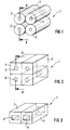
- the individual actuators 2 are hollow cylindrical Hollow bodies, each with an inner electrode on the inner circumference 3 and the other on the outer circumference Wear inner electrode 4.
- This embodiment can, like the exemplary embodiments described below, made of a piezoceramic material by extrusion getting produced.
- the inner electrodes 3 and 4 are by metallizing the respective peripheral surfaces educated.
- the individual actuators 2 baked together in a sintering process and with here external electrodes and electrical connections not visible for supplying an electrical voltage been provided.
- FIG. 1 Another embodiment is shown in FIG the geometric shape of individual actuators 5 with a cylindrical inner recess 6 and in Figure 3 is a another embodiment with regard to the geometric Form of individual actuators 7, each with an inner recess 8, which has a rectangular cross section, shown.
- FIG Hollow body 2 from Figure 1 or the hollow body 5 of Figure 2 can be seen along a section line A-A.
- the sides of the hollow body 2 or 5 or 7, on which the Contacting the internal electrodes 3 and 4 with external electrodes 9 and 10 is made, are designed here that the inner electrode 4 and the inner electrode 3 protrudes on the other side.
- the mutual contacting of the Internal electrodes 3 and 4 with a relatively simple processing step be made and thus one at a time electrical voltage between the inner electrode 4 on the inner circumference and the inner electrode 3 on the outer circumference of the Individual actuators 2 or 5 or 7 are available. Not over here Lateral connections shown, this voltage is on the outer electrodes 9 and 10 feasible.
Abstract
Description
Die Erfindung betrifft einen Piezoaktor, beispielsweise zur Betätigung eines mechanischen Bauteils wie ein Ventil oder dergleichen, nach den gattungsgemäßen Merkmalen des Hauptanspruchs.The invention relates to a piezo actuator, for example for actuating a mechanical component like a valve or the like, according to the generic characteristics of Main claim.
Es ist allgemein bekannt, dass unter Ausnutzung des sogenannten Piezoeffekts ein Piezoelement aus einem Material mit einer geeigneten Kristalistruktur aufgebaut, werden kann. Bei Anlage einer äußeren elektrischen Spannung erfolgt eine mechanische Reaktion des Piezoelements, die in Abhängigkeit von der Kristallstruktur und der Anlagebereiche der elektrischen Spannung einen Druck oder Zug in eine vorgebbare Richtung darstellt. Der Aufbau dieses Piezoaktors erfolgt in üblicher Weise durch Übereinanderstapeln mehreren Piezoschichten (Multilayer-Aktoren), wobei die Elektroden, über die die elektrische Spannung aufgebracht wird, jeweils zwischen den Schichten angeordnet werden.It is generally known that taking advantage of the so-called Piezo effect a piezo element made of one material with a suitable crystal structure can. When an external electrical voltage is applied a mechanical reaction of the piezo element, which in Dependence on the crystal structure and the investment areas a tension or tension in the electrical voltage represents a predeterminable direction. Building this Piezoactuators are usually stacked one above the other several piezo layers (multilayer actuators), whereby the electrodes through which the electrical voltage is applied, in each case arranged between the layers become.
Solche Piezoaktoren können beispielsweise für den Antrieb von kraftausgeglichenen Schaltventilen bei Kraftstoffeinspritzsystemen in Kraftfahrzeugen vorgesehen werden. Das bekannte Stapeln der Schichten erfordert einen relativ großen Herstellungsaufwand, wobei insbesondere auch die optimale Einstellung des für den jeweiligen Anwendungsfall benötigten Hubes, der Hubgeschwindigkeit und das Kraftvermögen durch eine geeignete geometrische Form des gesamten Lagen- bzw. Schichtaufbaus schwierig ist. Es ist dabei für sich gesehen auch bekannt, verschiedene, in bestimmten Wirkungsachsen auftretende Piezoeffekte, wie z.B. den λ31 Effekt, auszunutzen.Piezo actuators of this type can be provided, for example, for driving force-balanced switching valves in fuel injection systems in motor vehicles. The known stacking of the layers requires a relatively large amount of production work, and in particular the optimal setting of the stroke required for the respective application, the stroke speed and the force is difficult due to a suitable geometric shape of the entire layer or layer structure. It is also known per se to utilize various piezo effects that occur in specific axes of action, such as the λ 31 effect.
Der eingangs beschriebene Piezoaktor mit einem Aufbau von Einzelaktoren und zugeordneten Innenelektroden, der beispielsweise zur Betätigung eines mechanischen Bauteils verwendbar sein kann, ist in vorteilhafter Weise mit dadurch weitergebildet, dass die Einzelaktoren aus Hohlkörpern bestehen, bei denen die eine Innenelektrode am Innenumfang und die andere Innenelektrode am Außenumfang angeordnet ist.The piezo actuator described above with a structure of Individual actuators and associated internal electrodes, for example for actuating a mechanical component can be used in an advantageous manner further developed that the individual actuators from hollow bodies exist where the one inner electrode on the inner circumference and the other inner electrode on the outer circumference is arranged.
Die Einzelaktoren sind bei einer bevorzugten Ausführungsform jeweils übereinander und nebeneinander gestapelt. Durch eine derart optimierte Stapelform kann hier auch der sog. λ33 Piezoeffekt ausgenutzt werde, der z.B. ein um 50% vergrößertes Hubvermögen gegenüber dem schon eingangs erwähnten λ31 Effekt aufweist. Als mögliche geometrische Gestaltung der Hohlkörper bieten sich in vorteilhafter Weise Hohlkörper als Hohlzylinder oder Hohlkörper als Quader mit einer zylindrischen oder mit einer im Querschnitt rechteckigen Innenausnehmung an.In a preferred embodiment, the individual actuators are stacked one above the other and next to one another. By means of such an optimized stack shape, the so-called λ 33 piezo effect can also be used here, which, for example, has a 50% increased lifting capacity compared to the λ 31 effect already mentioned at the beginning. As a possible geometrical design of the hollow body, hollow bodies as hollow cylinders or hollow bodies as cuboids with a cylindrical or with a rectangular internal cross section are advantageous.
Der erfindungsgemäße Piezoaktor weist dabei insbesondere für kleine zu erzeugende Kräfte und schnelle Hübe eine einfache Kontur auf, wobei die Größe der Einzelaktoren im Millimeterbereich liegt. Je nach Anwendungsfall kann dabei über die Anzahl der Einzelaktoren in der Hubrichtung der mögliche Hub und über die Anzahl in der Breite, also quer zur Hubrichtung, das Kraftvermögen eingestellt werden.The piezo actuator according to the invention has in particular for small forces to be generated and fast strokes simple contour, the size of the individual actuators in Millimeter range. Depending on the application, this can be done about the number of individual actuators in the stroke direction the possible stroke and the number in width, so transverse to the stroke direction, the power can be set.
Auf einfache Weise kann die Kontur der Hohlkörper an den Seiten, an denen die Kontaktierung der Innenelektroden mit den Außenelektroden vorgenommen wird, so gestaltet sein, dass an einer Seite die Innenelektroden am Innenumfang und an der anderen Seite die Innenelektroden am Außenumfang einen vorgegebenen Bereich hervorstehen. Somit kann die wechselseitige Kontaktierung der Innenelektroden einfach vorgenommen werden, so dass jeweils eine elektrische Spannung zwischen der Innenelektrode am Innenumfang und der Innerlelektrode am Außenumfang der Einzelaktoren von seitlichen Anschlüssen zuführbar ist, die ein elektrisches Feld zur Bildung des Piezoeffekts in jedem Einzelaktor entstehen lässt.In a simple way, the contour of the hollow body to the Sides on which the contacting of the internal electrodes is made with the outer electrodes, so designed be that on one side the inner electrodes on the inner circumference and on the other side the inner electrodes on the outer circumference protrude a predetermined area. Consequently can the mutual contact of the internal electrodes simply be made so that one electrical at a time Voltage between the inner electrode on the inner circumference and the inner electrode on the outer circumference of the individual actuators can be fed from side connections, which is an electrical Field for forming the piezo effect in each individual actuator creates.
Bei einem besonders vorteilhaften Verfahren zur Herstellung eines Piezoaktor der zuvor beschriebenen Art werden aus einem Piezokeramikmaterial durch Extrusion die Hohlkörper gebildet. Zur Bildung der Innenelektroden werden die Hohlkörper am Innen- und am Außenumfang komplett metallisiert und anschließend die aus den Hohlkörpern gebildeten Einzelaktoren in einem Sinterprozess miteinander verbacken. Die Außenelektroden an den Seitenflächen werden durch Löten mit den jeweils zugehörigen Innenelektroden kontaktiert und an den Außenelektroden sind dann die elektrischen Anschlüsse für die Zuführung einer elektrischen Spannung anbringbar.In a particularly advantageous method of manufacture a piezo actuator of the type described above the hollow body from a piezoceramic material by extrusion educated. To form the inner electrodes the hollow body on the inner and outer circumference completely metallized and then those formed from the hollow bodies Individual actuators in a sintering process with each other bake. The outer electrodes on the side surfaces will be by soldering with the associated internal electrodes contacted and then on the outer electrodes electrical connections for the supply of an electrical Tension attachable.
Diese und weitere Merkmale von bevorzugten Weiterbildungen der Erfindung gehen außer aus den Ansprüchen auch aus der Beschreibung und den Zeichnungen hervor, wobei die einzelnen Merkmale jeweils für sich allein oder zu mehreren in Form von Unterkombinationen bei der Ausführungsform der Erfindung und auf anderen Gebieten verwirklicht sein und vorteilhafte sowie für sich schutzfähige Ausführungen darstellen können, für die hier Schutz beansprucht wird.These and other features of preferred further developments the invention also go out from the claims the description and the drawings, the individual characteristics individually or in groups in the form of sub-combinations in the embodiment of the invention and in other fields be and advantageous as well as protective designs can represent, for which protection is claimed here becomes.
Ausführungsbeispiele des erfindungsgemäßen Piezoaktors
mit Hohlkörpern als Einzelaktoren werden anhand der
Zeichnung erläutert. Es zeigen:
In Figur 1 ist ein Piezoaktor 1 gezeigt, der aus Einzelaktoren
2 aus einem Keramikmaterial mit einer geeigneten
Kristalistruktur aufgebaut ist, so dass unter Ausnutzung
des sogenannten Piezoeffekts bei Anlage einer äußeren
elektrischen Spannung an Innenelektroden eine mechanische
Reaktion der Einzelaktoren und somit des gesamten
Piezoaktors 1 erfolgt.In Figure 1, a
Bei der Figur 1 sind die Einzelaktoren 2 hohlzylindrische
Hohlkörper, die auf dem inneren Umfang jeweils eine Innenelektrode
3 und auf dem äußeren Umfang die jeweils andere
Innenelektrode 4 tragen. Dieses Ausführungsbeispiel
kann, wie auch die noch folgend beschriebenen Ausführungsbeispiele,
aus einem Piezokeramikmaterial durch Extrusion
hergestellt werden. Die Innenelektroden 3 und 4
werden durch eine Metallisierung der jeweiligen Umfangsflächen
gebildet. Abschließend sind die Einzelaktoren 2
in einem Sinterprozess miteinander verbacken und mit hier
nicht ersichtlichen Außenelektroden und elektrischen Anschlüssen
für die Zuführung einer elektrischen Spannung
versehen worden.In Figure 1, the
Zwischen den Innenelektroden 3 und 4 wirkt hierbei, bei
Anlage einer elektrischen Spannung, das größte Feld und
damit die größte mechanische Dehnung aufgrund des Piezoeffekts.
In der 90° Achse wirkt dabei der Dehnungseffekt
nur halb so stark, da die Feldlinien immer zwischen
den Elektroden laufen und damit senkrecht (90°) zur Elektrode
die Ausrichtung behindert ist.Here, between the
In Figur 2 ist ein anderes Ausführungsbeispiel hinsichtlich
der geometrischen Form von Einzelaktoren 5 mit einer
zylindrischen Innenausnehmung 6 und in Figur 3 ist ein
weiteres Ausführungsbeispiel hinsichtlich der geometrischen
Form von Einzelaktoren 7 mit jeweils einer Innenausnehmung
8, die einen rechteckigen Querschnitt aufweist,
gezeigt.Another embodiment is shown in FIG
the geometric shape of
Aus einem Detailschnitt nach Figur 4 ist die Kontur der
Hohlkörper 2 aus der Figur 1 oder der Hohlkörper 5 aus
der Figur 2 entlang einer Schnittlinie A-A zu erkennen.
Die Seiten der Hohlkörper 2 bzw. 5 oder 7, an denen die
Kontaktierung der Innenelektroden 3 und 4 mit Außenelektroden
9 und 10 vorgenommen wird, sind hierbei so gestaltet,
dass an einer Seite jeweils die Innenelektrode 4 und
an der anderen Seite jeweils die Innenelektrode 3 hervorsteht.
Somit kann die wechselseitige Kontaktierung der
Innenelektroden 3 und 4 mit einem relativ einfachen Bearbeitungsgang
vorgenommen werden und damit jeweils eine
elektrische Spannung zwischen der Innenelektrode 4 am Innenumfang
und der Innenelektrode 3 am Außenumfang der
Einzelaktoren 2 bzw. 5 oder 7 ansteht. Über hier nicht
dargestellte seitliche Anschlüssen ist diese Spannung an
die Außenelektroden 9 und 10 führbar.The contour of the detail section according to FIG
Claims (7)
Applications Claiming Priority (2)
| Application Number | Priority Date | Filing Date | Title |
|---|---|---|---|
| DE19938457 | 1999-08-13 | ||
| DE19938457A DE19938457A1 (en) | 1999-08-13 | 1999-08-13 | Piezo actuator and a method for its production |
Publications (2)
| Publication Number | Publication Date |
|---|---|
| EP1076367A2 true EP1076367A2 (en) | 2001-02-14 |
| EP1076367A3 EP1076367A3 (en) | 2004-01-07 |
Family
ID=7918326
Family Applications (1)
| Application Number | Title | Priority Date | Filing Date |
|---|---|---|---|
| EP00117140A Withdrawn EP1076367A3 (en) | 1999-08-13 | 2000-08-10 | Piezo actuator comprising a stack of hollow bodies |
Country Status (2)
| Country | Link |
|---|---|
| EP (1) | EP1076367A3 (en) |
| DE (1) | DE19938457A1 (en) |
Citations (3)
| Publication number | Priority date | Publication date | Assignee | Title |
|---|---|---|---|---|
| GB2239554A (en) * | 1989-12-21 | 1991-07-03 | Queensgate Instr Ltd | Precision position actuator |
| DE19626671C1 (en) * | 1996-07-03 | 1997-10-16 | Fraunhofer Ges Forschung | High-frequency piezoelectric power actuator apparatus with heat dissipation |
| DE19712923A1 (en) * | 1997-03-27 | 1998-10-01 | Bosch Gmbh Robert | Piezoelectric actuator |
Family Cites Families (1)
| Publication number | Priority date | Publication date | Assignee | Title |
|---|---|---|---|---|
| DE4033091C1 (en) * | 1990-10-18 | 1992-03-12 | Messerschmitt-Boelkow-Blohm Gmbh, 8012 Ottobrunn, De | Controlling elastic characteristics of sensor - by embedding electrostrictive fibres in electroconductive matrix on non-conductive matrix e.g. of silicon carbide |
-
1999
- 1999-08-13 DE DE19938457A patent/DE19938457A1/en not_active Withdrawn
-
2000
- 2000-08-10 EP EP00117140A patent/EP1076367A3/en not_active Withdrawn
Patent Citations (3)
| Publication number | Priority date | Publication date | Assignee | Title |
|---|---|---|---|---|
| GB2239554A (en) * | 1989-12-21 | 1991-07-03 | Queensgate Instr Ltd | Precision position actuator |
| DE19626671C1 (en) * | 1996-07-03 | 1997-10-16 | Fraunhofer Ges Forschung | High-frequency piezoelectric power actuator apparatus with heat dissipation |
| DE19712923A1 (en) * | 1997-03-27 | 1998-10-01 | Bosch Gmbh Robert | Piezoelectric actuator |
Also Published As
| Publication number | Publication date |
|---|---|
| DE19938457A1 (en) | 2001-02-22 |
| EP1076367A3 (en) | 2004-01-07 |
Similar Documents
| Publication | Publication Date | Title |
|---|---|---|
| EP0978148B1 (en) | Piezoelectric actuator | |
| EP1230688A1 (en) | Piezoelectric actuator | |
| EP1908131A1 (en) | Method for producing a monolithic piezo actuator with stack elements, monilithic piezo actuator with stack elements, and use of the piezo actuator | |
| DE102006035470A1 (en) | Method for producing a piezoelectric layer element | |
| EP1476907B1 (en) | Piezo actuator comprising a structured external electrode | |
| DE10147666A1 (en) | piezo element | |
| EP1579514B1 (en) | Piezo actuator and a method for producing the same | |
| EP1530807B1 (en) | Piezo actuator | |
| EP1579513B1 (en) | Piezo actuator | |
| DE102005052686A1 (en) | Method for manufacturing piezo actuator, involves coupling piezoelectric inactive end area with assigned end surface of piezoelectric active area with formation of transition section between piezoelectric active and inactive end area | |
| EP1076367A2 (en) | Piezo actuator comprising a stack of hollow bodies | |
| EP2617073B1 (en) | Tubular spring for receiving and pretensioning an actuator | |
| WO2001091198A1 (en) | Piezoelectric actuator | |
| WO2001024286A1 (en) | Piezo-electric actuator | |
| EP2798679B1 (en) | Piezo-stack with passivation, and a method for the passivation of a piezo-stack | |
| WO2006077245A1 (en) | Monolithic multilayer actuator and method for the production thereof | |
| DE102019110736B4 (en) | actuator | |
| DE10154634A1 (en) | Piezo element e.g. piezoelectric actuator for fuel injection valve in motor vehicle, has dimensions of layers set so that after sintering, contact formation involves processing only at side surfaces | |
| WO2004019424A2 (en) | Piezoelectric actuator | |
| DE19951118A1 (en) | Piezo actuator e.g. for valve, has multiple layer structure of piezo layers and internal electrodes and a number of external electrodes for each polarity of electrical voltage on outer sides of actuator | |
| WO2001089002A1 (en) | Piezo actuator | |
| DE10257952A1 (en) | Multi-layer piezoelectric actuator for activating a valve in a motor vehicle, has a neutral phase without an inner electrode layer between piezoelectric layers near an inner electrode | |
| WO2001024287A2 (en) | Internal electrodes for a stacked piezoactuator and method for producing the same | |
| DE102004002087A1 (en) | Piezoactuator and a method for its production | |
| WO2001078159A1 (en) | Piezoelectric multilayer actuator and method for producing the same |
Legal Events
| Date | Code | Title | Description |
|---|---|---|---|
| PUAI | Public reference made under article 153(3) epc to a published international application that has entered the european phase |
Free format text: ORIGINAL CODE: 0009012 |
|
| AK | Designated contracting states |
Kind code of ref document: A2 Designated state(s): AT BE CH CY DE DK ES FI FR GB GR IE IT LI LU MC NL PT SE |
|
| AX | Request for extension of the european patent |
Free format text: AL;LT;LV;MK;RO;SI |
|
| PUAL | Search report despatched |
Free format text: ORIGINAL CODE: 0009013 |
|
| AK | Designated contracting states |
Kind code of ref document: A3 Designated state(s): AT BE CH CY DE DK ES FI FR GB GR IE IT LI LU MC NL PT SE |
|
| AX | Request for extension of the european patent |
Extension state: AL LT LV MK RO SI |
|
| RIC1 | Information provided on ipc code assigned before grant |
Ipc: 7H 01L 41/047 B Ipc: 7H 01L 41/09 B Ipc: 7H 01L 41/24 B Ipc: 7H 01L 41/083 A |
|
| AKX | Designation fees paid | ||
| REG | Reference to a national code |
Ref country code: DE Ref legal event code: 8566 |
|
| STAA | Information on the status of an ep patent application or granted ep patent |
Free format text: STATUS: THE APPLICATION IS DEEMED TO BE WITHDRAWN |
|
| 18D | Application deemed to be withdrawn |
Effective date: 20040708 |