EP1076166A2 - Verfahren und Vorrichtung für die Frischluftbestimmung an einer Brennkraftmaschine - Google Patents
Verfahren und Vorrichtung für die Frischluftbestimmung an einer Brennkraftmaschine Download PDFInfo
- Publication number
- EP1076166A2 EP1076166A2 EP00114056A EP00114056A EP1076166A2 EP 1076166 A2 EP1076166 A2 EP 1076166A2 EP 00114056 A EP00114056 A EP 00114056A EP 00114056 A EP00114056 A EP 00114056A EP 1076166 A2 EP1076166 A2 EP 1076166A2
- Authority
- EP
- European Patent Office
- Prior art keywords
- fresh air
- engine
- air mass
- internal combustion
- air
- Prior art date
- Legal status (The legal status is an assumption and is not a legal conclusion. Google has not performed a legal analysis and makes no representation as to the accuracy of the status listed.)
- Granted
Links
- 238000002485 combustion reaction Methods 0.000 title claims abstract description 42
- 238000000034 method Methods 0.000 title claims abstract description 19
- 238000011144 upstream manufacturing Methods 0.000 claims abstract description 3
- 238000002347 injection Methods 0.000 claims description 26
- 239000007924 injection Substances 0.000 claims description 26
- 239000000446 fuel Substances 0.000 claims description 19
- 238000010586 diagram Methods 0.000 claims description 5
- 238000005259 measurement Methods 0.000 abstract 1
- 230000006870 function Effects 0.000 description 5
- 239000000779 smoke Substances 0.000 description 5
- 230000006399 behavior Effects 0.000 description 3
- 230000001419 dependent effect Effects 0.000 description 3
- 230000000694 effects Effects 0.000 description 3
- 230000001133 acceleration Effects 0.000 description 2
- 239000002245 particle Substances 0.000 description 2
- 230000001105 regulatory effect Effects 0.000 description 2
- 230000001052 transient effect Effects 0.000 description 2
- 230000003139 buffering effect Effects 0.000 description 1
- 230000006835 compression Effects 0.000 description 1
- 238000007906 compression Methods 0.000 description 1
- 230000001276 controlling effect Effects 0.000 description 1
- 230000009897 systematic effect Effects 0.000 description 1
Images

Classifications
-
- F—MECHANICAL ENGINEERING; LIGHTING; HEATING; WEAPONS; BLASTING
- F02—COMBUSTION ENGINES; HOT-GAS OR COMBUSTION-PRODUCT ENGINE PLANTS
- F02D—CONTROLLING COMBUSTION ENGINES
- F02D41/00—Electrical control of supply of combustible mixture or its constituents
- F02D41/02—Circuit arrangements for generating control signals
- F02D41/18—Circuit arrangements for generating control signals by measuring intake air flow
-
- F—MECHANICAL ENGINEERING; LIGHTING; HEATING; WEAPONS; BLASTING
- F02—COMBUSTION ENGINES; HOT-GAS OR COMBUSTION-PRODUCT ENGINE PLANTS
- F02D—CONTROLLING COMBUSTION ENGINES
- F02D41/00—Electrical control of supply of combustible mixture or its constituents
- F02D41/0002—Controlling intake air
- F02D41/0007—Controlling intake air for control of turbo-charged or super-charged engines
-
- F—MECHANICAL ENGINEERING; LIGHTING; HEATING; WEAPONS; BLASTING
- F02—COMBUSTION ENGINES; HOT-GAS OR COMBUSTION-PRODUCT ENGINE PLANTS
- F02D—CONTROLLING COMBUSTION ENGINES
- F02D2200/00—Input parameters for engine control
- F02D2200/02—Input parameters for engine control the parameters being related to the engine
- F02D2200/04—Engine intake system parameters
- F02D2200/0402—Engine intake system parameters the parameter being determined by using a model of the engine intake or its components
-
- F—MECHANICAL ENGINEERING; LIGHTING; HEATING; WEAPONS; BLASTING
- F02—COMBUSTION ENGINES; HOT-GAS OR COMBUSTION-PRODUCT ENGINE PLANTS
- F02D—CONTROLLING COMBUSTION ENGINES
- F02D41/00—Electrical control of supply of combustible mixture or its constituents
- F02D41/0025—Controlling engines characterised by use of non-liquid fuels, pluralities of fuels, or non-fuel substances added to the combustible mixtures
- F02D41/0047—Controlling exhaust gas recirculation [EGR]
- F02D41/0065—Specific aspects of external EGR control
-
- Y—GENERAL TAGGING OF NEW TECHNOLOGICAL DEVELOPMENTS; GENERAL TAGGING OF CROSS-SECTIONAL TECHNOLOGIES SPANNING OVER SEVERAL SECTIONS OF THE IPC; TECHNICAL SUBJECTS COVERED BY FORMER USPC CROSS-REFERENCE ART COLLECTIONS [XRACs] AND DIGESTS
- Y02—TECHNOLOGIES OR APPLICATIONS FOR MITIGATION OR ADAPTATION AGAINST CLIMATE CHANGE
- Y02T—CLIMATE CHANGE MITIGATION TECHNOLOGIES RELATED TO TRANSPORTATION
- Y02T10/00—Road transport of goods or passengers
- Y02T10/10—Internal combustion engine [ICE] based vehicles
- Y02T10/12—Improving ICE efficiencies
Definitions
- the invention relates to a method for determining a in the combustion chamber of an engine Fresh air mass fed in, in which the fresh air flow in a fresh air supply duct the engine is measured upstream from a pressure stage and the fresh air mass is calculated on the basis of this measured value. It also relates to a control device for combustion in an internal combustion engine.
- Modern internal combustion engines especially for motor vehicles, have exhaust gas recirculation Mistake.
- the exhaust gas is recirculated from the internal combustion engine Exhaust gas in a ratio that can be regulated with the help of a control valve with fresh air mixed and fed back to the machine.
- the amount of exhaust gas returned as well of the fuel injected into the combustion chamber of the internal combustion engine become dependent regulated by a fresh air supply quantity detected by an air mass sensor in order to keep the machine's emissions low.
- the air mass sensor is located in the intake tract of the machine and is often far from the intake valves of the combustion chamber of the engine removed so that between the sensor and the valves can have a considerable air storage volume.
- this storage volume has a buffering effect, so that it too Deviations between the actual fresh air consumption of the engine and in fresh air flow measured by the air mass sensor can come.
- the object of the invention is a method for determining a in the combustion chamber To specify fresh air mass fed into the engine, even in unsteady operating phases effective regulation allowed.
- This object is achieved in that in a method of the type mentioned Pressure changes in the fresh air supply channel between the pressure stage and an inlet of the combustion chamber measured and these pressure changes in the calculations of Fresh air mass are taken into account.
- the method can be used particularly advantageously if the pressure stage is a compressor. Basically, however, it can be used in conjunction with pressure stages of any type, the one Time difference between a change in the fresh air consumption of the engine and the associated change in the measured by the air mass sensor Can cause fresh air flow.
- This determination method can advantageously be used as part of a method for controlling the fuel injection quantity of an engine. Since the determination method according to the invention allows practically no delay to correctly calculate the fresh air mass actually fed into the combustion chamber of the engine when the engine operation changes, the amount of fuel injected can also be correctly limited in such a change phase so that a given air ratio ⁇ min is not undercut .
- this air ratio ⁇ min is expediently predetermined as a function of the speed of the internal combustion engine, so that a control that is optimally adapted to the current speed is possible.
- the value ⁇ min is expediently also dependent on a desired fuel injection quantity, which the driver of the vehicle can specify, for example, by actuating the accelerator pedal.
- a control device suitable for performing the methods described above is conventionally comprised of an air mass sensor and an arithmetic circuit to determine the fresh air mass fed into a combustion chamber on the basis of the Air mass sensor detected mass flow and the speed of the internal combustion engine. About that it also includes a pressure sensor and a computing circuit for converting one Pressure change in an air mass flow.
- a temperature sensor for detecting an air temperature is also expedient intended.
- the control device also expediently comprises a storage element for a first one Map of a size that is a minimum permissible air ratio of the internal combustion engine Function of their speed and, possibly, a desired fuel injection quantity.
- An arithmetic circuit is also for calculating an allowable fuel injection amount based on the size of the first map and the air mass flow detected by the air mass sensor intended.
- a storage element for a second characteristic diagram can be provided that has a desired one Injection quantity as a function of the speed and a control parameter such as the position of an accelerator pedal of the vehicle.
- the control device preferably further comprises a circuit which is under one of the Storage device of the second map and the injection quantity supplied by the Arithmetic circuit calculates the injection value and selects the smaller value thereby realizing a limitation of the fuel injection quantity.
- Figure 1 shows an idealized representation of a diesel engine with exhaust gas turbocharging and exhaust gas recirculation and its fresh air supply and exhaust system.
- An air mass sensor 1 is in a fresh air intake duct between a (not shown) Air filter and a compressor 2 arranged. Between the compressor 2 and the intake valves of the motor 3 extend lines whose fluidic behavior for the purposes of the present invention by a storage volume 4 and a throttling point 5 can be described. There is a between the throttle point 5 and the engine 3 Inlet manifold 6, via an exhaust gas recirculation line 7 with an exhaust manifold 8 at the exhaust outlet the motor 3 is connected.
- the exhaust gas recirculation line 7 contains a recirculation valve 9 that controls the back flow of exhaust gas to the intake manifold.
- the not returned Portion of the exhaust gas from the exhaust manifold 8 passes through a turbine 10, where it is at atmospheric pressure relaxed while driving the compressor 2, and finally reaches the exhaust 11.
- Figure 2 shows schematically the structure of a part of a control circuit which approximately determines the combustion chamber fresh air mass m air, BR . It comprises a differential circuit 20 which receives the signal m ⁇ HFM of the air mass sensor 1 at a non-inverting input and receives a signal at an inverting input which corresponds to the right term representing the buffer effect of the storage volume on the right side of Formula 1. This signal is supplied by a multiplier 21 which receives at one input a signal representative of the time derivative of the pressure p L and at another input a signal inversely proportional to the temperature T L.
- the pressure derivative signal dp L / dt can be obtained with the aid of a computing circuit, not shown, which receives and differentiates signals from a pressure sensor arranged on the storage volume 4.
- a differentiating pressure sensor can also be used directly.
- the signal inversely proportional to the temperature, the value of which also depends on the storage volume V Ers can be predetermined if it is assumed that the assumption of an average intake air temperature already allows a sufficiently precise control.
- a temperature sensor can also be provided on the memory 4, which allows the temperature T L to be measured continuously and to be included in the calculation.
- the differential circuit 20 provides a measure of the actual air flow into the engine 3, ie for the time derivative m ⁇ ELS_in of the amount of air actually sucked in by the engine 3.
- an integrator 22 supplies the mass m air, BR of the fresh air actually taken in by a combustion chamber of the engine in the course of a cycle.
- the combustion chamber fresh air mass m air, BR determined in this way is used as an input variable for a control method which serves to reduce particle emissions which are generated in the phases of unsteady operation of the engine 3 and which are caused by rapid increases in the injection quantity. Since the particle emissions rise sharply when the air falls below a certain air ratio ⁇ , the method must ensure that, depending on the engine speed and the desired fuel injection quantity desired by a driver of the motor vehicle and specified by more or less hard pedaling of an accelerator pedal, a minimum air ratio ⁇ min does not is undercut.
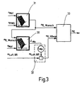
- This maximum permissible injection quantity is calculated by the arithmetic circuit 32 in FIG. 3.
- the arithmetic circuit carries out multiplication by the fixed factor L Min and division.
- the size stored in the smoke map 30 can include the product of ⁇ min and L min from the outset, so that the multiplication can be omitted.
- ⁇ min in the smoke map 30 can be replaced by its reciprocal value, so that the arithmetic circuit 32 performs a - technically simpler - multiplication instead of a division.
- the desired injection quantity m E, request is supplied by a second memory element 31, in which this variable is stored in the form of a second map, referred to as the driving behavior map, as a function of the engine speed n Mot and the accelerator pedal position S PWG .
- a minimum value circuit 33 receives the desired injection quantity from the driving behavior map 31 as well as the maximum permissible injection quantity from the arithmetic circuit 32, and outputs the smaller of the two values as an injection soli value m E , which is the one to be injected into the combustion chambers of the engine Indicates the amount of fuel.
- the actual amount of fuel injected is not measured in most direct injection diesel engines. Therefore, the amount of fuel actually injected can deviate from the target amount m E. This would have a negative impact on smoke control using the control method described above. It is therefore advisable to include a correction of the injected fuel quantity in the process.
- This can be done via an additional sensor that can detect a deviation between the target and actual injection quantity.
- the control device is expediently designed to carry out a comparison between the air ratio ⁇ expected for the determined injection quantity m E and the actual air ratio measured by the lambda sensor and to take corrective measures if a systematic deviation of the two values is determined.
- Such measures can consist, for example, of a change in the factor L Min used by the arithmetic circuit 32 or a change of the data of the characteristic diagrams.
Landscapes
- Engineering & Computer Science (AREA)
- Chemical & Material Sciences (AREA)
- Combustion & Propulsion (AREA)
- Mechanical Engineering (AREA)
- General Engineering & Computer Science (AREA)
- Electrical Control Of Air Or Fuel Supplied To Internal-Combustion Engine (AREA)
- Combined Controls Of Internal Combustion Engines (AREA)
- Measuring Fluid Pressure (AREA)
- Sampling And Sample Adjustment (AREA)
Abstract
Description
Claims (10)
- Verfahren zur Bestimmung einer in den Brennraum einer Kraftmaschine (3) eingespeisten Frischluftmasse, bei dem der Frischluftstrom in einem Frischluftzufuhrkanal der Kraftmaschine stromaufwärts vor einer Druckstufe (2) gemessen wird und die Frischluftmasse anhand dieses Meßwertes berechnet wird, dadurch gekennzeichnet, daß Druckänderungen in dem Frischluftzufuhrkanal in einem zwischen der Druckstufe (2) und einem Einlaß (6) des Brennraumes liegenden Bereich (4) gemessen werden und diese Druckänderungen bei der Berechnung der Frischluftmasse berücksichtigt werden.
- Verfahren nach Anspruch 1, dadurch gekennzeichnet, daß die Druckstufe (2) ein Verdichter ist.
- Verfahren zur Steuerung der Kraftstoffeinspritzmenge einer Kraftmaschine (3), dadurch gekennzeichnet, daß die in den Brennraum der Kraftmaschine (3) eingespeiste Frischluftmenge nach einem Verfahren nach Anspruch 1 oder 2 berechnet wird, und die zu der Frischluftmenge eingespritzte Kraftstoffmenge auf einen Wert begrenzt wird, der ein gegebenes Luftverhältnis λMin nicht unterschreitet.
- Verfahren nach Anspruch 3, dadurch gekennzeichnet, daß λMin in Abhängigkeit von der Drehzahl der Kraftmaschine (3) vorgegeben wird.
- Steuervorrichtung für die Verbrennung in einer Brennkraftmaschine, mit einem Luftmassensensor (1) und einer Rechenschaltung (22) zum Ermitteln der in einen Brennraum der Brennkraftmaschine eingespeisten Frischluftmasse anhand des von dem Luftmassensensor (1) erfaßten Luftmassenstromes und der Drehzahl der Bennkraftmaschine, dadurch gekennzeichnet, daß sie einen Drucksensor und eine Rechenschaltung (20, 21) zum Umrechnen einer Druckänderung in einen Luftverbrauch der Brennkraftmaschine umfaßt.
- Steuervorrichtung nach Anspruch 5, dadurch gekennzeichnet, daß sie einen Temperatursensor zum Erfassen einer Lufttemperatur umfaßt.
- Steuervorrichtung nach Anspruch 5 oder 6, dadurch gekennzeichnet, daß sie ein Speicherelement (30) für ein erstes Kennfeld für eine Größe umfaßt, die ein minimal zulässiges Luftverhältnis der Kraftmaschine (3) als Funktion ihrer Drehzahl angibt.
- Steuerschaltung nach Anspruch 7, gekennzeichnet durch eine Arithmetikschaltung (32) zum Berechnen einer zulässigen Kraftstoffeinspritzmenge anhand der Größe des ersten Kennfeldes.
- Steuervorrichtung nach einer der Ansprüche 5 bis 8, dadurch gekennzeichnet, daß sie ein Speicherelement (31) für ein zweites Kennfeld umfaßt, das eine gewünschte Einspritzmenge als Funktion der Drehzahl und eines Steuerparameters angibt.
- Steuervorrichtung nach Anspruch 8 und 9, gekennzeichnet durch eine Schaltung (33) zum Auswählen des kleineren Wertes unter einer von der Speichereinrichtung (31) des zweiten Kennfeldes gelieferten Einspritzmenge und einer von der Arithmetikschaltung (32) berechneten Einspritzmenge.
Applications Claiming Priority (2)
| Application Number | Priority Date | Filing Date | Title |
|---|---|---|---|
| DE19938260A DE19938260A1 (de) | 1999-08-12 | 1999-08-12 | Verfahren und Vorrichtung für die Frischluftbestimmung an einer Brennkraftmaschine |
| DE19938260 | 1999-08-12 |
Publications (3)
| Publication Number | Publication Date |
|---|---|
| EP1076166A2 true EP1076166A2 (de) | 2001-02-14 |
| EP1076166A3 EP1076166A3 (de) | 2003-05-07 |
| EP1076166B1 EP1076166B1 (de) | 2007-02-07 |
Family
ID=7918193
Family Applications (1)
| Application Number | Title | Priority Date | Filing Date |
|---|---|---|---|
| EP00114056A Expired - Lifetime EP1076166B1 (de) | 1999-08-12 | 2000-07-06 | Verfahren und Vorrichtung für die Frischluftbestimmung an einer Brennkraftmaschine |
Country Status (3)
| Country | Link |
|---|---|
| EP (1) | EP1076166B1 (de) |
| AT (1) | ATE353397T1 (de) |
| DE (2) | DE19938260A1 (de) |
Cited By (7)
| Publication number | Priority date | Publication date | Assignee | Title |
|---|---|---|---|---|
| EP1247967A3 (de) * | 2001-04-05 | 2003-05-07 | Bayerische Motoren Werke Aktiengesellschaft | Verfahren zum Bestimmen des Luftmassenstroms vom Saugrohr in den Zylinder einer Brennkraftmaschine |
| EP1559891A1 (de) * | 2004-01-28 | 2005-08-03 | Delphi Technologies, Inc. | Rauchverringerungsverfahren zur Steuerung einer aufgeladenen Brennkraftmaschine |
| EP1398490A3 (de) * | 2002-09-10 | 2006-06-21 | Volkswagen AG | Verfahren zum Betreiben einer Brennkraftmaschine |
| WO2006064154A1 (fr) * | 2004-12-17 | 2006-06-22 | Peugeot Citroen Automobiles Sa | Procede de determination de la masse des gaz brules residuels restant dans le cylindre d'un moteur a combustion interne |
| WO2008062292A3 (en) * | 2006-11-24 | 2008-07-24 | Toyota Motor Co Ltd | Fuel injection device and control method therefor |
| WO2008110422A1 (de) * | 2007-03-15 | 2008-09-18 | Continental Automotive Gmbh | Verfahren zum ermitteln und einregeln des luftmassenstroms im saugrohr eines verbrennungsmotors sowie zugehöriges steuergerät |
| CN101571077A (zh) * | 2008-04-29 | 2009-11-04 | 福特环球技术公司 | 增加直喷式增压内燃发动机的扭矩的方法 |
Families Citing this family (6)
| Publication number | Priority date | Publication date | Assignee | Title |
|---|---|---|---|---|
| EP1507967A2 (de) | 2001-11-28 | 2005-02-23 | Volkswagen Aktiengesellschaft | Verfahren zur bestimmung der zusammensetzung des gasgemisches in einem brennraum eines verbrennungsmotors mit abgasrückführung |
| DE10158250A1 (de) * | 2001-11-28 | 2003-06-18 | Volkswagen Ag | Verfahren zur Bestimmung des Frischluftmassenstroms eines Verbrennungsmotors mit Abgasrückführung und entsprechend ausgestaltetes Steuersystem für einen Verbrennungsmotor |
| DE102004047099B3 (de) * | 2004-09-29 | 2006-03-16 | Bayerische Motoren Werke Ag | Verfahren zur Bestimmung der Frischluftmasse eines Verbrennungsmotors |
| DE102004049737A1 (de) * | 2004-10-13 | 2006-06-22 | Bayerische Motoren Werke Ag | Verfahren zur Bestimmung des Frischluftmassenstroms eines Verbrennungsmotors |
| US7302335B1 (en) * | 2006-11-03 | 2007-11-27 | Gm Global Technology Operations, Inc. | Method for dynamic mass air flow sensor measurement corrections |
| DE102007030233A1 (de) * | 2007-06-29 | 2009-01-08 | Ford Global Technologies, LLC, Dearborn | Verfahren zur Bestimmung des Luftmassenstromes einer mit einem Abgasturbolader ausgestatteten Brennkraftmaschine |
Family Cites Families (7)
| Publication number | Priority date | Publication date | Assignee | Title |
|---|---|---|---|---|
| CZ319497A3 (cs) * | 1995-04-10 | 1999-01-13 | Siemens Aktiengesellschaft | Způsob modelového určení množství vzduchu, proudícího do válce, respektive do válců spalovacího motoru |
| DE19525815B4 (de) * | 1995-07-15 | 2007-05-03 | Robert Bosch Gmbh | Verfahren zur Erfassung des Lastsignals einer Brennkraftmaschine |
| KR100462458B1 (ko) * | 1996-03-15 | 2005-05-24 | 지멘스 악티엔게젤샤프트 | 외부배기가스를재순환하는내연기관의실린더로유입되는맑은공기의질량을모델을이용하여결정하는방법 |
| DE19740969B4 (de) * | 1997-04-01 | 2010-05-20 | Robert Bosch Gmbh | Verfahren zum Betreiben einer Brennkraftmaschine und Brennkraftmaschine |
| DE19756619B4 (de) * | 1997-04-01 | 2007-03-15 | Robert Bosch Gmbh | System zum Betreiben einer Brennkraftmaschine insbesondere für ein Kraftfahrzeug |
| WO1999014476A1 (de) * | 1997-09-17 | 1999-03-25 | Robert Bosch Gmbh | Verfahren und vorrichtung zur bestimmung einer gasfüllung eines verbrennungsmotors |
| US6370935B1 (en) * | 1998-10-16 | 2002-04-16 | Cummins, Inc. | On-line self-calibration of mass airflow sensors in reciprocating engines |
-
1999
- 1999-08-12 DE DE19938260A patent/DE19938260A1/de not_active Withdrawn
-
2000
- 2000-07-06 DE DE50014032T patent/DE50014032D1/de not_active Expired - Lifetime
- 2000-07-06 AT AT00114056T patent/ATE353397T1/de not_active IP Right Cessation
- 2000-07-06 EP EP00114056A patent/EP1076166B1/de not_active Expired - Lifetime
Non-Patent Citations (1)
| Title |
|---|
| None |
Cited By (10)
| Publication number | Priority date | Publication date | Assignee | Title |
|---|---|---|---|---|
| EP1247967A3 (de) * | 2001-04-05 | 2003-05-07 | Bayerische Motoren Werke Aktiengesellschaft | Verfahren zum Bestimmen des Luftmassenstroms vom Saugrohr in den Zylinder einer Brennkraftmaschine |
| EP1398490A3 (de) * | 2002-09-10 | 2006-06-21 | Volkswagen AG | Verfahren zum Betreiben einer Brennkraftmaschine |
| EP1559891A1 (de) * | 2004-01-28 | 2005-08-03 | Delphi Technologies, Inc. | Rauchverringerungsverfahren zur Steuerung einer aufgeladenen Brennkraftmaschine |
| WO2006064154A1 (fr) * | 2004-12-17 | 2006-06-22 | Peugeot Citroen Automobiles Sa | Procede de determination de la masse des gaz brules residuels restant dans le cylindre d'un moteur a combustion interne |
| FR2879659A1 (fr) * | 2004-12-17 | 2006-06-23 | Peugeot Citroen Automobiles Sa | Methode de calcul par simulation du transfert des gaz d'un moteur essence de vehicule automobile |
| WO2008062292A3 (en) * | 2006-11-24 | 2008-07-24 | Toyota Motor Co Ltd | Fuel injection device and control method therefor |
| US8209108B2 (en) | 2006-11-24 | 2012-06-26 | Toyota Jidosha Kabushiki Kaisha | Fuel injection device and control method therefor |
| CN101553654B (zh) * | 2006-11-24 | 2013-01-02 | 丰田自动车株式会社 | 燃料喷射设备及其控制方法 |
| WO2008110422A1 (de) * | 2007-03-15 | 2008-09-18 | Continental Automotive Gmbh | Verfahren zum ermitteln und einregeln des luftmassenstroms im saugrohr eines verbrennungsmotors sowie zugehöriges steuergerät |
| CN101571077A (zh) * | 2008-04-29 | 2009-11-04 | 福特环球技术公司 | 增加直喷式增压内燃发动机的扭矩的方法 |
Also Published As
| Publication number | Publication date |
|---|---|
| EP1076166B1 (de) | 2007-02-07 |
| DE19938260A1 (de) | 2001-02-15 |
| EP1076166A3 (de) | 2003-05-07 |
| ATE353397T1 (de) | 2007-02-15 |
| DE50014032D1 (de) | 2007-03-22 |
Similar Documents
| Publication | Publication Date | Title |
|---|---|---|
| EP1247016B1 (de) | Verfahren und vorrichtung zur steuerung einer brennkraftmaschine mit einem luftsystem | |
| EP1701025B1 (de) | Verfahren zur Bestimmung der Zusammensetzung des Gasgemisches in einem Brennraum eines Verbrennungsmotors mit Abgasrückführung | |
| EP1440231B1 (de) | Verfahren und vorrichtung zur steuerung eines elektrisch betriebenen laders | |
| DE69822985T2 (de) | Motordrehmoment-Steuerungssystem | |
| DE102015200906B4 (de) | Steuervorrichtung und Steuerverfahren für einen Verbrennungsmotor mit einem Auflader | |
| DE19752271A1 (de) | Verfahren und Vorrichtung zur adaptiven Abgastemperatur-Schätzung und -Steuerung | |
| DE2849554A1 (de) | Einrichtung zum festlegen der zusammensetzung des gas-inhalts von zylindern bei brennkraftmaschinen | |
| DE4207541B4 (de) | System zur Steuerung einer Brennkraftmaschine | |
| DE102014224399B4 (de) | Schätzvorrichtung und Verfahren für eine Zylinderansaugluftmenge eines Verbrennungsmotors | |
| EP1076166A2 (de) | Verfahren und Vorrichtung für die Frischluftbestimmung an einer Brennkraftmaschine | |
| DE112006003091T5 (de) | Steuervorrichtung für eine Brennkraftmaschine | |
| WO2016034370A1 (de) | Verfahren und vorrichtung zur ansteuerung eines abgasrückführventils einer aufgeladenen brennkraftmaschine mit abgasrückführung | |
| DE112007000409B4 (de) | Verfahren zum Steuern von Turbinenauslasstemperaturen in einem Dieselmotor | |
| DE69825670T2 (de) | Drehmomentsteuerung einer Brennkraftmaschine | |
| EP0411321B1 (de) | Verfahren zur Steuerung der Kraftstoffzumessung bei einer Dieselbrennkraftmaschine | |
| DE102010043897B4 (de) | Verfahren und Vorrichtung zum Betreiben eines Verbrennungsmotors | |
| EP1623103A1 (de) | Verfahren zur drehzahl überwachung eines bi-turboladers | |
| DE102011089847B4 (de) | Maschinensteuervorrichtung | |
| DE102004052429A1 (de) | Einspritzsteuergerät für eine Kraftmaschine | |
| WO2008009506A1 (de) | Verfahren und vorrichtung zur bestimmung des umgebungsdrucks mit hilfe eines ladedrucksensors bei einem turbomotor | |
| DE10256241A1 (de) | Verfahren und Vorrichtung zur Steuerung einer eine Abgasrückführung aufweisenden Brennkraftmaschine | |
| DE19618385B4 (de) | Verfahren und Vorrichtung zur Steuerung einer Brennkraftmaschine | |
| EP1586756B1 (de) | Verfahren und Vorrichtung zum Betreiben einer Brennkraftmaschine | |
| DE102004038733A1 (de) | Verfahren und Vorrichtung zum Betreiben einer Brennkraftmaschine | |
| DE102008042819B4 (de) | Verfahren und Vorrichtung zum Bestimmen einer gesamten Zylinderfüllung und/oder der aktuellen Restgasrate bei einem Verbrennungsmotor mit Abgasrückführung |
Legal Events
| Date | Code | Title | Description |
|---|---|---|---|
| PUAI | Public reference made under article 153(3) epc to a published international application that has entered the european phase |
Free format text: ORIGINAL CODE: 0009012 |
|
| AK | Designated contracting states |
Kind code of ref document: A2 Designated state(s): AT BE CH CY DE DK ES FI FR GB GR IE IT LI LU MC NL PT SE |
|
| AX | Request for extension of the european patent |
Free format text: AL;LT;LV;MK;RO;SI |
|
| PUAL | Search report despatched |
Free format text: ORIGINAL CODE: 0009013 |
|
| AK | Designated contracting states |
Designated state(s): AT BE CH CY DE DK ES FI FR GB GR IE IT LI LU MC NL PT SE |
|
| AX | Request for extension of the european patent |
Extension state: AL LT LV MK RO SI |
|
| RIC1 | Information provided on ipc code assigned before grant |
Ipc: 7F 02D 33/02 B Ipc: 7F 02D 41/10 B Ipc: 7F 02D 41/14 B Ipc: 7F 02D 41/18 A |
|
| 17P | Request for examination filed |
Effective date: 20031107 |
|
| AKX | Designation fees paid |
Designated state(s): AT BE CH CY DE DK ES FI FR GB GR IE IT LI LU MC NL PT SE |
|
| GRAP | Despatch of communication of intention to grant a patent |
Free format text: ORIGINAL CODE: EPIDOSNIGR1 |
|
| GRAS | Grant fee paid |
Free format text: ORIGINAL CODE: EPIDOSNIGR3 |
|
| GRAA | (expected) grant |
Free format text: ORIGINAL CODE: 0009210 |
|
| AK | Designated contracting states |
Kind code of ref document: B1 Designated state(s): AT BE CH CY DE DK ES FI FR GB GR IE IT LI LU MC NL PT SE |
|
| PG25 | Lapsed in a contracting state [announced via postgrant information from national office to epo] |
Ref country code: IE Free format text: LAPSE BECAUSE OF FAILURE TO SUBMIT A TRANSLATION OF THE DESCRIPTION OR TO PAY THE FEE WITHIN THE PRESCRIBED TIME-LIMIT Effective date: 20070207 Ref country code: FI Free format text: LAPSE BECAUSE OF FAILURE TO SUBMIT A TRANSLATION OF THE DESCRIPTION OR TO PAY THE FEE WITHIN THE PRESCRIBED TIME-LIMIT Effective date: 20070207 Ref country code: NL Free format text: LAPSE BECAUSE OF FAILURE TO SUBMIT A TRANSLATION OF THE DESCRIPTION OR TO PAY THE FEE WITHIN THE PRESCRIBED TIME-LIMIT Effective date: 20070207 Ref country code: DK Free format text: LAPSE BECAUSE OF FAILURE TO SUBMIT A TRANSLATION OF THE DESCRIPTION OR TO PAY THE FEE WITHIN THE PRESCRIBED TIME-LIMIT Effective date: 20070207 |
|
| REG | Reference to a national code |
Ref country code: GB Ref legal event code: FG4D Free format text: NOT ENGLISH |
|
| REG | Reference to a national code |
Ref country code: CH Ref legal event code: EP |
|
| REG | Reference to a national code |
Ref country code: IE Ref legal event code: FG4D Free format text: LANGUAGE OF EP DOCUMENT: GERMAN |
|
| REF | Corresponds to: |
Ref document number: 50014032 Country of ref document: DE Date of ref document: 20070322 Kind code of ref document: P |
|
| PG25 | Lapsed in a contracting state [announced via postgrant information from national office to epo] |
Ref country code: SE Free format text: LAPSE BECAUSE OF FAILURE TO SUBMIT A TRANSLATION OF THE DESCRIPTION OR TO PAY THE FEE WITHIN THE PRESCRIBED TIME-LIMIT Effective date: 20070507 |
|
| GBT | Gb: translation of ep patent filed (gb section 77(6)(a)/1977) |
Effective date: 20070412 |
|
| PG25 | Lapsed in a contracting state [announced via postgrant information from national office to epo] |
Ref country code: ES Free format text: LAPSE BECAUSE OF FAILURE TO SUBMIT A TRANSLATION OF THE DESCRIPTION OR TO PAY THE FEE WITHIN THE PRESCRIBED TIME-LIMIT Effective date: 20070518 |
|
| PG25 | Lapsed in a contracting state [announced via postgrant information from national office to epo] |
Ref country code: PT Free format text: LAPSE BECAUSE OF FAILURE TO SUBMIT A TRANSLATION OF THE DESCRIPTION OR TO PAY THE FEE WITHIN THE PRESCRIBED TIME-LIMIT Effective date: 20070709 |
|
| NLV1 | Nl: lapsed or annulled due to failure to fulfill the requirements of art. 29p and 29m of the patents act | ||
| REG | Reference to a national code |
Ref country code: IE Ref legal event code: FD4D |
|
| EN | Fr: translation not filed | ||
| PLBE | No opposition filed within time limit |
Free format text: ORIGINAL CODE: 0009261 |
|
| STAA | Information on the status of an ep patent application or granted ep patent |
Free format text: STATUS: NO OPPOSITION FILED WITHIN TIME LIMIT |
|
| 26N | No opposition filed |
Effective date: 20071108 |
|
| BERE | Be: lapsed |
Owner name: VOLKSWAGEN A.G. Effective date: 20070731 |
|
| REG | Reference to a national code |
Ref country code: CH Ref legal event code: PL |
|
| PG25 | Lapsed in a contracting state [announced via postgrant information from national office to epo] |
Ref country code: IT Free format text: LAPSE BECAUSE OF FAILURE TO SUBMIT A TRANSLATION OF THE DESCRIPTION OR TO PAY THE FEE WITHIN THE PRESCRIBED TIME-LIMIT Effective date: 20070207 Ref country code: FR Free format text: LAPSE BECAUSE OF FAILURE TO SUBMIT A TRANSLATION OF THE DESCRIPTION OR TO PAY THE FEE WITHIN THE PRESCRIBED TIME-LIMIT Effective date: 20070928 Ref country code: CH Free format text: LAPSE BECAUSE OF NON-PAYMENT OF DUE FEES Effective date: 20070731 Ref country code: GR Free format text: LAPSE BECAUSE OF FAILURE TO SUBMIT A TRANSLATION OF THE DESCRIPTION OR TO PAY THE FEE WITHIN THE PRESCRIBED TIME-LIMIT Effective date: 20070508 Ref country code: MC Free format text: LAPSE BECAUSE OF NON-PAYMENT OF DUE FEES Effective date: 20070731 Ref country code: LI Free format text: LAPSE BECAUSE OF NON-PAYMENT OF DUE FEES Effective date: 20070731 |
|
| PG25 | Lapsed in a contracting state [announced via postgrant information from national office to epo] |
Ref country code: BE Free format text: LAPSE BECAUSE OF NON-PAYMENT OF DUE FEES Effective date: 20070731 |
|
| PG25 | Lapsed in a contracting state [announced via postgrant information from national office to epo] |
Ref country code: FR Free format text: LAPSE BECAUSE OF FAILURE TO SUBMIT A TRANSLATION OF THE DESCRIPTION OR TO PAY THE FEE WITHIN THE PRESCRIBED TIME-LIMIT Effective date: 20070207 Ref country code: AT Free format text: LAPSE BECAUSE OF NON-PAYMENT OF DUE FEES Effective date: 20070706 |
|
| PG25 | Lapsed in a contracting state [announced via postgrant information from national office to epo] |
Ref country code: CY Free format text: LAPSE BECAUSE OF FAILURE TO SUBMIT A TRANSLATION OF THE DESCRIPTION OR TO PAY THE FEE WITHIN THE PRESCRIBED TIME-LIMIT Effective date: 20070207 |
|
| PG25 | Lapsed in a contracting state [announced via postgrant information from national office to epo] |
Ref country code: LU Free format text: LAPSE BECAUSE OF NON-PAYMENT OF DUE FEES Effective date: 20070706 |
|
| PGFP | Annual fee paid to national office [announced via postgrant information from national office to epo] |
Ref country code: GB Payment date: 20160729 Year of fee payment: 17 Ref country code: DE Payment date: 20160731 Year of fee payment: 17 |
|
| REG | Reference to a national code |
Ref country code: DE Ref legal event code: R119 Ref document number: 50014032 Country of ref document: DE |
|
| GBPC | Gb: european patent ceased through non-payment of renewal fee |
Effective date: 20170706 |
|
| PG25 | Lapsed in a contracting state [announced via postgrant information from national office to epo] |
Ref country code: DE Free format text: LAPSE BECAUSE OF NON-PAYMENT OF DUE FEES Effective date: 20180201 Ref country code: GB Free format text: LAPSE BECAUSE OF NON-PAYMENT OF DUE FEES Effective date: 20170706 |