EP1076143A1 - Verriegelungselement - Google Patents
Verriegelungselement Download PDFInfo
- Publication number
- EP1076143A1 EP1076143A1 EP00116041A EP00116041A EP1076143A1 EP 1076143 A1 EP1076143 A1 EP 1076143A1 EP 00116041 A EP00116041 A EP 00116041A EP 00116041 A EP00116041 A EP 00116041A EP 1076143 A1 EP1076143 A1 EP 1076143A1
- Authority
- EP
- European Patent Office
- Prior art keywords
- bolt
- locking
- fastening part
- locking element
- connecting part
- Prior art date
- Legal status (The legal status is an assumption and is not a legal conclusion. Google has not performed a legal analysis and makes no representation as to the accuracy of the status listed.)
- Granted
Links
- 239000000463 material Substances 0.000 claims abstract description 7
- 229920003023 plastic Polymers 0.000 abstract description 2
- 239000004033 plastic Substances 0.000 abstract description 2
- 238000005452 bending Methods 0.000 abstract 1
- 239000013013 elastic material Substances 0.000 description 1
- 239000002184 metal Substances 0.000 description 1
Images



Classifications
-
- E—FIXED CONSTRUCTIONS
- E05—LOCKS; KEYS; WINDOW OR DOOR FITTINGS; SAFES
- E05C—BOLTS OR FASTENING DEVICES FOR WINGS, SPECIALLY FOR DOORS OR WINDOWS
- E05C19/00—Other devices specially designed for securing wings, e.g. with suction cups
- E05C19/06—Other devices specially designed for securing wings, e.g. with suction cups in which the securing part if formed or carried by a spring and moves only by distortion of the spring, e.g. snaps
Definitions
- the invention relates to a locking element, in particular for household appliances, through which two components movable relative to each other can be released can be locked according to claim 1.
- Locking elements according to the invention can be used for any purpose are used, especially for locking frames, lids, flaps, Windows, doors, sliders, drawers, boxes, cassettes and the like, each pivotally or linearly arranged components of Household appliances, e.g. of extractor hoods, but also of any other devices, such as radios and music systems, as well as for furniture and parts of buildings.
- the object of the invention is to provide a locking element develop, which is easy to assemble manually, only on one of the two components to be locked together must be attached, in the manner of a Push button is actuated, and preferably from a one-piece Material body can be produced.
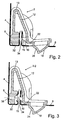
- Fig. 1 shows in the locked position, and Fig. 2 in the unlocked position, one Cross section of a locking element 2 according to the invention, in particular for Household appliances, by means of which two components 4 movable relative to one another and 6 are releasably lockable with each other.
- the locking element 2 contains a fastening part 8 (or several in parallel side by side fasteners) for fastening to one Component 4; a bar 10 (or several bars arranged side by side) to lock the relevant other component 6; a connecting part 12 (or more connecting parts arranged side by side), which the Bolt 10 connects to the fastening part 8, the bolt 10 in its Locking movement direction 14 protrudes from the connecting part 12 and the connecting part 12 at least partially, preferably on it entire length of the fastening part 8 to the bolt 10, from one resiliently flexible section or material, through which or through which the bolt 10 together with the area 16 connected to it of the connecting part 12 in the locking movement direction 14 relative to Fastening part 8 is pushed into the locking position shown in Fig.
- the fastening part 8, the bolt 10 and the connecting part 12 are in the preferred embodiment together from a one-piece material body made of plastic.
- a one-piece material body made of plastic.
- the connecting part 12 has two in legs 12-1 and 12-2 arranged at an angle of less than 90 ° to one another, which are connected to each other in the angular tip 13 and in the angular plane against each other by manual pressure on the push button 18 or by a Shear force from the other component 6 on an inclined run-up surface 15 of the Latch 10 are movable.
- the fastening part 8 is on one leg 12-1 and the latch 10 and the push button 18 are on the other leg 12-2 of the Connection part 12 each provided at a distance from the angle tip 13.
- the Bolt 10 protrudes from the other leg 12-2 towards one leg 12-1 away.
- the bolt 10 is arranged opposite the fastening part 8 and its Locking movement direction 14 is directed against the fastening part 8.
- the push button 18 is formed on an extension 22 of the connecting part 12, which are opposite to or at the bar 10 opposite Locking movement direction 14 extends away from the bolt 10.
- the push button 18 is provided with a manually operable pressure surface 24, which extends obliquely to the locking movement direction 14, wherein it the same side as the bolt 10 and its direction of locking movement 14 shows, i.e. opposite to the manual actuation force required is around the bolt 10 against the resilient force of the connecting part 12th from the locking position of FIG. 1 to the unlocking position of FIG. 2 to press.
- the push button 18, at least its pressure surface 24, is located with respect to FIG the spring-elastic required for locking and unlocking Part 12-1, 12-2, 13 of the connecting part 12 on the outer facing away Side of the latch 10.
- the fastening part 8 is at the end of the angle tip 13 remote from the a leg 12-1 of the connecting part 12 is arranged.
- the fastening part 8 is with at least one catch projection 26 for snapping into a catch opening 28 of one component 4 and thus for fastening the connecting part 12 this component 4 provided.
- the detent projection 26 can be resilient, either by spring-elastic material of the locking element 2 and / or by forming the detent projection 16 on a spring elastic across it movable fastening section on the fastening part 8.
- the component 4 has one of a base leg 33 U-shaped inwards to the locking element 2 bent area 32, in which the fastening part 8 from the inside Sliding seat is insertable.
- the latch opening 28 is in the projecting inward free leg 31 of the U-shaped area 32 opposite a latch receiving opening 34 formed, the latter in a parallel to one leg 31 inwardly projecting leg 35 of the other component 6 is formed and serves to receive and lock the bolt 10.
- the leg 31 is U-shaped Area 32 resilient in the transverse direction so that the fastening part 8th in the U-shaped area 32 with lateral guidance, preferably with lateral guidance Tension, can be used and the detent projection 26 into the detent opening 28 can snap into place. As a result, the fastening part 8 becomes in the U-shaped region 32 kept wobble-free.
- the fastening part 8 is attached to a component 4, the bolt 10 protrudes in 1 through the locking opening 34 and is preferably supported on the detent projection 26 and can by manual pressure on the push button 18 away from the fastening part 8 Locking opening 34 moved out into the unlocking position of FIG. 2 become.
- the push button 18 protrudes through a push button opening 38 or is at least manually accessible through this.
- the locking opening 34 is in the transverse to the locking direction 14 in the interior of a device itself extending leg 35 of the component 6 is formed.
- the push button opening 38 is formed in a base leg 44 of the component 6, which is parallel to the locking movement direction 14 and at right angles to it extends inside leg 35.
- one or more openings 36 for one or more catch projections 26 in the fastening part 8 for fastening it to the one component 4 by means of a Connecting element such as a screw may be provided.
- the two components 4 and 6 consist of sheet metal, but can also consist of one other material.
- the one component 4 is a fixed Component is and the other component 6 relative to the fixed component 4th is pivotable about a pivot axis.
- This can be a pivot axis 46 which is perpendicular to the locking movement direction 14 according to FIG. 1 4, but it can also be a pivot axis 48 according to FIG extends parallel to the locking movement direction 14 of the bolt 10.
- the movable component 6 can be relative to the stationary component 4 in the direction of the with the locking opening 34th provided leg 40, i.e. perpendicular to the direction of locking movement 14 can be arranged to be linearly movable, instead of about a pivot axis 46 or 48 to be pivotable.
- the mobility of the Components 4 and 6 are interchanged, so that one component 4 movable and the other component 6 is the stationary component.
- the fastening part 8 is fastened to a movable component 6 and the locking opening 34 and the push button opening 38 in a stationary component 4 can be formed around the bolt 10 and Record push button 18.
- FIGS. 5, 6 and 7 can from the fastening part 8 distant end of the connecting part 12 two or more bars 10 can be provided in parallel at a distance from each other, which there are designated by the reference numerals 10A and 10B.
- the fastening part 8 with the at least one bolt 10 or 10A, 10B instead of by a single connecting part 12 by several in parallel with Distance adjacently arranged connecting parts can be connected or the connecting part 12 at least partially in parallel at a distance adjacent sections can be divided, for example in the Angle tip 13 through the two parts 13A and 13B, which the two legs Connect 12-1 and 12-2 of the connecting part 12 together.
- the Fastening part 8 can be provided with one or more fastening openings 36 Attachment to a component 4 or 6, or with an or several catch projections 26 according to FIG. 1.
- the connecting part 12 is on its end remote from the fastening part 8 in addition to the bolts 10A and 10B also provided with a push button 18 which corresponds to the 1 and 2 on an extension 22 of the connecting part 12th can be formed.
- 1, 2 and 4 are with 2, the 3 with 2-2, and the locking element according to the 5, 6 and 7 with 2-3. Identical or essentially the same, Functionally corresponding parts are provided with the same reference numbers.
- the manual printing surface 24 of the push button 18 parallel or at right angles to Locking movement direction 14 may be formed on the push button 18.
- the extension 22 of the Connecting part 12 is at right angles or at an angle to Extend locking movement direction 14 beyond the bolt 10 and the Push button 18 can move in the locking direction 14, i.e. in the same Direction like bar 10, stretch away from it.
Landscapes
- Engineering & Computer Science (AREA)
- Mechanical Engineering (AREA)
- Connection Of Plates (AREA)
- Hooks, Suction Cups, And Attachment By Adhesive Means (AREA)
Abstract
Description
- Fig. 1
- schematisch einen Querschnitt durch ein Verriegelungselement nach der Erfindung in Verriegelungsstellung,
- Fig. 2
- das Verriegelungselement von Fig. 1 in Entriegelungsstellung,
- Fig. 3
- eine weitere Ausführungsform eines Verriegelungselementes nach der Erfindung,
- Fig. 4
- eine weitere Verwendungsmöglichkeit von Verriegelungselementen nach den Figuren 1 und 2 in gleicher Querschnittsansicht dargestellt,
- Fig. 5
- perspektivisch eine weitere Ausführungsform eines Verriegelungselementes nach der Erfindung,
- Fig. 6
- eine andere perspektivische Ansicht des Verriegelungselementes von Fig. 5,
- Fig. 7
- eine nochmals andere perspektivische Darstellung des Verriegelungselementes der Figuren 5 und 6.
Claims (10)
- Verriegelungselement, durch welches zwei relativ zueinander bewegbare Bauelemente (4, 6) miteinander lösbar verriegelbar sind, enthaltend mindestens einen Befestigungsteil (8) zur Befestigung an einem der beiden Bauelemente (4); mindestens einen Riegel (10) zum Verriegeln des betreffenden anderen Bauelements (6); mindestens einen Verbindungsteil (12), welcher den Riegel (10) mit dem Befestigungsteil (8) verbindet, wobei der Riegel (10) in seiner Verriegelungsbewegungsrichtung (14) von dem Verbindungsteil (12) wegragt und wobei der Verbindungsteil (12) mindestens in einem Abschnitt federelastisch biegsam ist, so daß der Riegel (10) durch diese Federelastizität zusammen mit dem mit ihm verbundenen Bereich des Verbindungsteiles (12) in Verriegelungsbewegungsrichtung (14) relativ zum Befestigungsteil (8) in eine Verriegelungsstellung gedrängt wird und entgegen der Federkraft des Verbindungsteiles (12) entgegen der Verriegelungsbewegungsrichtung (14) in eine Entriegelungsstellung manuell bewegbar ist; einen Druckknopf (18) zum manuellen Bewegen des Riegels (10) entgegen seiner Verriegelungsbewegungsrichtung (14) und entgegen der Federkraft des federelastischen Verbindungsteiles (12) in die Entriegelungsstellung.
- Verriegelungselement nach Anspruch 1, dadurch gekennzeichnet, daß der Befestigungsteil (8), der Riegel (10) und der Verbindungsteil (12) zusammen aus einem einstückigen Materialkörper bestehen.
- Verriegelungselement nach Anspruch 1 oder 2, dadurch gekennzeichnet, daß der Verbindungsteil (12) zwei in einem Winkel von weniger als 90° zueinander angeordnete Schenkel (12-1, 12-2) hat, die in der Winkelspitze (13) miteinander verbunden sind und in der Winkelebene wegen der genannten Federelastizität gegeneinander federelastisch manuell bewegbar sind, daß der Befestigungsteil (8) am einen Schenkel (12-1) und der Riegel (10) sowie der Druckknopf (18) am anderen Schenkel (12-2) vorgesehen sind, und daß der Riegel (10) von dem anderen (12-2) Schenkel in Richtung zum einen Schenkel (12-1) wegragt.
- Verriegelungselement nach Anspruch 3, dadurch gekennzeichnet, daß der Riegel (10) gegenüber von dem Befestigungsteil (8) angeordnet ist und seine Verriegelungsbewegungsrichtung (14) gegen den Befestigungsteil (8) gerichtet ist.
- Verriegelungselement nach einem der vorhergehenden Ansprüche, dadurch gekennzeichnet, daß der Druckknopf (18) an einer vom Befestigungsteil (8) weiter entfernten Stelle als der Riegel (10) angeordnet ist.
- Verriegelungselement nach einem der vorhergehenden Ansprüche, dadurch gekennzeichnet, daß der Druckknopf (18) quer zur Verriegelungsbewegungsrichtung (14) des Riegels (10) über die Lage des Riegels (10) hinaus von der Seite des Riegels hinausragt, die von der Seite des Riegels abgewandt ist, auf welcher der Riegel durch den Verbindungsteil (12) mit dem Befestigungsteil (8) verbunden ist.
- Verriegelungselement nach einem der vorhergehenden Ansprüche, dadurch gekennzeichnet, daß der Druckknopf (18) mit einer manuellen Druckfläche (24) versehen ist, welche schräg zur Verriegelungsbewegungsrichtung (14) des Riegels (10) sich erstreckt.
- Verriegelungselement nach einem der vorhergehenden Ansprüche, dadurch gekennzeichnet, daß der Befestigungsteil (8) mit mindestens einer Rastnase (26) zum Einrasten an dem einen Bauteil (4) versehen ist.
- Verriegelungselement nach einem der vorhergehenden Ansprüche, dadurch gekennzeichnet, daß der Befestigungsteil (8) mindestens eine Öffnung (36) zum Einsetzen eines ihn mit dem einen Bauteil (4) verbindenden Verbindungselementes aufweist.
- Verwendung von mindestens einem Verriegelungselement nach einem der vorhergehenden Ansprüche zur Verriegelung von Rahmen, Deckeln, Klappen, Fenstern, Türen, Schiebern, Schubladen, Kästen, Kassetten und ähnlichen, je schwenkbar oder linear verschiebbar angeordneten Bauelementen (6) von Haushaltsgeräten.
Applications Claiming Priority (2)
| Application Number | Priority Date | Filing Date | Title |
|---|---|---|---|
| DE1999137625 DE19937625A1 (de) | 1999-08-10 | 1999-08-10 | Verriegelungselement |
| DE19937625 | 1999-08-10 |
Publications (2)
| Publication Number | Publication Date |
|---|---|
| EP1076143A1 true EP1076143A1 (de) | 2001-02-14 |
| EP1076143B1 EP1076143B1 (de) | 2007-09-12 |
Family
ID=7917780
Family Applications (1)
| Application Number | Title | Priority Date | Filing Date |
|---|---|---|---|
| EP00116041A Expired - Lifetime EP1076143B1 (de) | 1999-08-10 | 2000-07-26 | Haushaltsgerät mit einem Verriegelungselement |
Country Status (3)
| Country | Link |
|---|---|
| EP (1) | EP1076143B1 (de) |
| DE (2) | DE19937625A1 (de) |
| ES (1) | ES2292391T3 (de) |
Cited By (1)
| Publication number | Priority date | Publication date | Assignee | Title |
|---|---|---|---|---|
| RU2239039C1 (ru) * | 2003-03-25 | 2004-10-27 | Федеральное государственное унитарное предприятие "Государственный космический научно-производственный центр им. М.В.Хруничева" | Замок |
Families Citing this family (1)
| Publication number | Priority date | Publication date | Assignee | Title |
|---|---|---|---|---|
| DE102016107097B4 (de) * | 2016-04-18 | 2025-10-30 | Miele & Cie. Kg | Dunstabzugshaube und Verfahren zum Montieren einer Dunstabzugshaube |
Citations (4)
| Publication number | Priority date | Publication date | Assignee | Title |
|---|---|---|---|---|
| US2520725A (en) * | 1946-08-26 | 1950-08-29 | Tinnerman Products Inc | Support construction and fastening device therefor |
| FR2135608A1 (de) * | 1971-05-04 | 1972-12-22 | Siemens Ag | |
| GB1378668A (en) * | 1973-08-23 | 1974-12-27 | Mothercare Ltd | Catch |
| US4865366A (en) * | 1988-07-05 | 1989-09-12 | Whirlpool Corporation | Toe panel retainer clip for dryer |
Family Cites Families (5)
| Publication number | Priority date | Publication date | Assignee | Title |
|---|---|---|---|---|
| US2123588A (en) * | 1936-05-15 | 1938-07-12 | Gen Motors Corp | Refrigerating apparatus |
| DE3940061C2 (de) * | 1989-12-04 | 1994-06-30 | Bauer Hans Juergen | Türschloß |
| US5158329A (en) * | 1991-09-20 | 1992-10-27 | Southco, Inc. | Slam latch |
| DE4421022A1 (de) * | 1994-06-16 | 1995-12-21 | Klaus Rehahn Gmbh & Co Kg | Schnappverschluß für Behälter |
| US6053544A (en) * | 1998-05-11 | 2000-04-25 | White Consoldiated Industries, Inc. | Locking handle for refrigerators |
-
1999
- 1999-08-10 DE DE1999137625 patent/DE19937625A1/de not_active Ceased
-
2000
- 2000-07-26 DE DE50014646T patent/DE50014646D1/de not_active Expired - Lifetime
- 2000-07-26 EP EP00116041A patent/EP1076143B1/de not_active Expired - Lifetime
- 2000-07-26 ES ES00116041T patent/ES2292391T3/es not_active Expired - Lifetime
Patent Citations (4)
| Publication number | Priority date | Publication date | Assignee | Title |
|---|---|---|---|---|
| US2520725A (en) * | 1946-08-26 | 1950-08-29 | Tinnerman Products Inc | Support construction and fastening device therefor |
| FR2135608A1 (de) * | 1971-05-04 | 1972-12-22 | Siemens Ag | |
| GB1378668A (en) * | 1973-08-23 | 1974-12-27 | Mothercare Ltd | Catch |
| US4865366A (en) * | 1988-07-05 | 1989-09-12 | Whirlpool Corporation | Toe panel retainer clip for dryer |
Cited By (1)
| Publication number | Priority date | Publication date | Assignee | Title |
|---|---|---|---|---|
| RU2239039C1 (ru) * | 2003-03-25 | 2004-10-27 | Федеральное государственное унитарное предприятие "Государственный космический научно-производственный центр им. М.В.Хруничева" | Замок |
Also Published As
| Publication number | Publication date |
|---|---|
| EP1076143B1 (de) | 2007-09-12 |
| ES2292391T3 (es) | 2008-03-16 |
| DE50014646D1 (de) | 2007-10-25 |
| DE19937625A1 (de) | 2001-02-15 |
Similar Documents
| Publication | Publication Date | Title |
|---|---|---|
| EP1845222B1 (de) | Klipsbefestigung für die Montage von Beschlageinrichtungen, wie Verschlüsse, Scharnierteile, Griffe in Durchbrüchen in einer dünnen Wand | |
| EP2142822B1 (de) | Quersteg und glied einer leitungsführungseinrichtung mit quersteg | |
| WO2020232483A1 (de) | Möbelbeschlag | |
| DE202005007586U1 (de) | Behälter mit Rastverschluss | |
| WO2005083209A1 (de) | Verschluss zur montage in durchbrüchen in einer dünnen wand | |
| EP3535824B1 (de) | Sammelschienenhalter und eine entsprechende anordnung | |
| DE102006016277A1 (de) | Schnellverschluss | |
| EP0843064B1 (de) | Beschlag für ein Fenster | |
| DE102019204525A1 (de) | Befestigungsklemme | |
| EP0459987B1 (de) | Gerätegehäuse mit zwei gehäuseschalen | |
| EP1076143B1 (de) | Haushaltsgerät mit einem Verriegelungselement | |
| DE102019103655A1 (de) | Schubkasten | |
| WO2005071193A1 (de) | Stangenschloss zur montage in einem durchbruch in einer dünnen wand (indirekte klipsbefestigung) | |
| DE29617989U1 (de) | Möbelsystem und Profilleiste dafür | |
| EP4146888A1 (de) | Scharnierbaugruppe mit gemeinsamer betätigung | |
| AT503457B1 (de) | Scharnier für die verschwenkbare anlenkung von klappen oder türflügeln am korpus von möbelstücken | |
| DE102017125609B3 (de) | Bandteil | |
| DE29812639U1 (de) | Schließblech | |
| DE202006020037U1 (de) | Rahmenkonstruktion für einen Schaltschrank, Schaltschrank und Bausatz für den Schaltschrank | |
| EP1253272A1 (de) | Beschlaganordnung mit Beschlagteilsicherung | |
| EP1365092A2 (de) | Schiebeverschluss für eine schwenkbare Abdeckklappe | |
| DE102023102127A1 (de) | Eckverbinder mit Spreizelement | |
| EP0448907A1 (de) | Scharnieranordnung für die Tür eines Schaltschrankes und Verfahren zur Montage | |
| DE4101218A1 (de) | Beschlagteil | |
| DE202004016010U1 (de) | Schnappbefestigung zur Festlegung einer dünnen Wand an einen Wandträger |
Legal Events
| Date | Code | Title | Description |
|---|---|---|---|
| PUAI | Public reference made under article 153(3) epc to a published international application that has entered the european phase |
Free format text: ORIGINAL CODE: 0009012 |
|
| AK | Designated contracting states |
Kind code of ref document: A1 Designated state(s): DE ES FR GB IT SE |
|
| AX | Request for extension of the european patent |
Free format text: AL;LT;LV;MK;RO;SI |
|
| 17P | Request for examination filed |
Effective date: 20010814 |
|
| AKX | Designation fees paid |
Free format text: DE ES FR GB IT SE |
|
| 17Q | First examination report despatched |
Effective date: 20020227 |
|
| RAP1 | Party data changed (applicant data changed or rights of an application transferred) |
Owner name: BSH BOSCH UND SIEMENS HAUSGERAETE GMBH |
|
| RTI1 | Title (correction) |
Free format text: HOUSEHOLD APPLIANCE WITH A LOCKING ELEMENT |
|
| GRAP | Despatch of communication of intention to grant a patent |
Free format text: ORIGINAL CODE: EPIDOSNIGR1 |
|
| GRAS | Grant fee paid |
Free format text: ORIGINAL CODE: EPIDOSNIGR3 |
|
| GRAA | (expected) grant |
Free format text: ORIGINAL CODE: 0009210 |
|
| AK | Designated contracting states |
Kind code of ref document: B1 Designated state(s): DE ES FR GB IT SE |
|
| REG | Reference to a national code |
Ref country code: GB Ref legal event code: FG4D Free format text: NOT ENGLISH |
|
| REF | Corresponds to: |
Ref document number: 50014646 Country of ref document: DE Date of ref document: 20071025 Kind code of ref document: P |
|
| REG | Reference to a national code |
Ref country code: ES Ref legal event code: FG2A Ref document number: 2292391 Country of ref document: ES Kind code of ref document: T3 |
|
| GBV | Gb: ep patent (uk) treated as always having been void in accordance with gb section 77(7)/1977 [no translation filed] | ||
| PG25 | Lapsed in a contracting state [announced via postgrant information from national office to epo] |
Ref country code: GB Free format text: LAPSE BECAUSE OF FAILURE TO SUBMIT A TRANSLATION OF THE DESCRIPTION OR TO PAY THE FEE WITHIN THE PRESCRIBED TIME-LIMIT Effective date: 20070912 |
|
| PG25 | Lapsed in a contracting state [announced via postgrant information from national office to epo] |
Ref country code: SE Free format text: LAPSE BECAUSE OF FAILURE TO SUBMIT A TRANSLATION OF THE DESCRIPTION OR TO PAY THE FEE WITHIN THE PRESCRIBED TIME-LIMIT Effective date: 20071212 |
|
| PLBE | No opposition filed within time limit |
Free format text: ORIGINAL CODE: 0009261 |
|
| STAA | Information on the status of an ep patent application or granted ep patent |
Free format text: STATUS: NO OPPOSITION FILED WITHIN TIME LIMIT |
|
| 26N | No opposition filed |
Effective date: 20080613 |
|
| PGFP | Annual fee paid to national office [announced via postgrant information from national office to epo] |
Ref country code: ES Payment date: 20100726 Year of fee payment: 11 |
|
| PGFP | Annual fee paid to national office [announced via postgrant information from national office to epo] |
Ref country code: IT Payment date: 20100727 Year of fee payment: 11 Ref country code: DE Payment date: 20100731 Year of fee payment: 11 |
|
| PG25 | Lapsed in a contracting state [announced via postgrant information from national office to epo] |
Ref country code: DE Free format text: LAPSE BECAUSE OF NON-PAYMENT OF DUE FEES Effective date: 20120201 |
|
| REG | Reference to a national code |
Ref country code: DE Ref legal event code: R119 Ref document number: 50014646 Country of ref document: DE Effective date: 20120201 |
|
| PG25 | Lapsed in a contracting state [announced via postgrant information from national office to epo] |
Ref country code: IT Free format text: LAPSE BECAUSE OF NON-PAYMENT OF DUE FEES Effective date: 20110726 |
|
| REG | Reference to a national code |
Ref country code: ES Ref legal event code: FD2A Effective date: 20121207 |
|
| PG25 | Lapsed in a contracting state [announced via postgrant information from national office to epo] |
Ref country code: ES Free format text: LAPSE BECAUSE OF NON-PAYMENT OF DUE FEES Effective date: 20110727 |
|
| PG25 | Lapsed in a contracting state [announced via postgrant information from national office to epo] |
Ref country code: FR Free format text: LAPSE BECAUSE OF FAILURE TO SUBMIT A TRANSLATION OF THE DESCRIPTION OR TO PAY THE FEE WITHIN THE PRESCRIBED TIME-LIMIT Effective date: 20070912 |