EP1075916A2 - Process and die for making closed-end ceramic tubes - Google Patents
Process and die for making closed-end ceramic tubes Download PDFInfo
- Publication number
- EP1075916A2 EP1075916A2 EP00117116A EP00117116A EP1075916A2 EP 1075916 A2 EP1075916 A2 EP 1075916A2 EP 00117116 A EP00117116 A EP 00117116A EP 00117116 A EP00117116 A EP 00117116A EP 1075916 A2 EP1075916 A2 EP 1075916A2
- Authority
- EP
- European Patent Office
- Prior art keywords
- end cap
- ceramic material
- tube
- cap forming
- reservoir
- Prior art date
- Legal status (The legal status is an assumption and is not a legal conclusion. Google has not performed a legal analysis and makes no representation as to the accuracy of the status listed.)
- Withdrawn
Links
Images
Classifications
-
- B—PERFORMING OPERATIONS; TRANSPORTING
- B28—WORKING CEMENT, CLAY, OR STONE
- B28B—SHAPING CLAY OR OTHER CERAMIC COMPOSITIONS; SHAPING SLAG; SHAPING MIXTURES CONTAINING CEMENTITIOUS MATERIAL, e.g. PLASTER
- B28B21/00—Methods or machines specially adapted for the production of tubular articles
- B28B21/02—Methods or machines specially adapted for the production of tubular articles by casting into moulds
- B28B21/08—Methods or machines specially adapted for the production of tubular articles by casting into moulds by slip-casting; Moulds therefor
-
- B—PERFORMING OPERATIONS; TRANSPORTING
- B28—WORKING CEMENT, CLAY, OR STONE
- B28B—SHAPING CLAY OR OTHER CERAMIC COMPOSITIONS; SHAPING SLAG; SHAPING MIXTURES CONTAINING CEMENTITIOUS MATERIAL, e.g. PLASTER
- B28B3/00—Producing shaped articles from the material by using presses; Presses specially adapted therefor
- B28B3/20—Producing shaped articles from the material by using presses; Presses specially adapted therefor wherein the material is extruded
- B28B3/26—Extrusion dies
- B28B3/2627—Extrusion dies using means for making hollow objects with transverse walls, e.g. hollow objects closed on all sides
Definitions
- the present invention relates to a process and die for forming an end cap in a ceramic tube in which the ceramic tube is extruded into an end cap forming cavity defined in the die. More particularly, the present invention relates to such a process and die in which ceramic material is backfilled into the end cap forming cavity to compact the ceramic material so that the ceramic material within the end cap has a substantially uniform density.
- closed-end tubes Due to the high failure rate of such open-ended tubes, the industry has sought to develop closed-end tubes. However, this has not been a simple task because for closed-end tubes to be of commercial value, it is important that the operational and performance characteristics remain the same throughout the length of the tube including the tube end. Such tube ends must, therefore, have a uniform thickness density and strength, in relation to the tube lengths.
- Ceramic tubes may be made by molding, casting, extrusion, as well as other methods known to those of skilled in the art. Commercial ceramic tubes are typically made by extrusion to provide tubes that have uniform thickness, density and strength throughout the tube length.
- the ceramic material usually comprises a ceramic oxide powder in a binder.
- the ceramic oxide powder/binder system is typically made into a formable paste, extruded through a die to form a tube in a "green" state, thermally treated to partially remove the binder to leave a bisque fired body, followed by sintering and densification by high temperature heat treatment. If the tubes are to be closed at one end, tube closure or capping is done prior to preparation of the bisque fired body.
- tube closure methods of the prior art have proven unsatisfactory for ceramic tubes.
- tube closure has been accomplished by plugging or capping.
- Plugging requires preparation of the plug in a separate operation from formation of the tube. Due to the fragility of the green body, plugging is typically done manually by moistening the plug, inserting it into an open end and molding the pieces together. Closure of tubes by plugging results in the production of tube ends having varying density and strength. Also due to the necessity to carefully control the jointing, tube closure by plugging does not represent a commercially viable means of production.
- extrusion of a tube requires that material be forced through a extrusion die that has an annulus at the center of which is a mandrel.
- the difference in diameters of the annulus and mandrel governs the tube wall thickness.
- the mandrel is located centrally in the annulus typically by an array of suspension lets, oriented in a circular pattern at regular intervals such as at a 90-degree spacing, commonly referred to as a "spider".
- the material is split into four sections as it passes over the mandrel and "spider”, and then is reunited as it passes beyond the annulus.
- Caps formed by this method typically exhibit “ghost” fissures from the 4-way division of material over the extrusion mandrel. The reason for this is the division of material produced discontinuities within the density of the ceramic material forming the end cap. Sintering of such caps do not appear to heal or the green body defects result in failure of the formed tubes at the end cap region.
- the present invention provides a method of capping an extruded tube by formation of an end cap having a uniform density to in turn provide a uniform strength through the tube length and end cap.
- the present invention provides a process for forming an end cap in an end of a ceramic tube.
- an end cap forming die is positioned against a extrusion die.
- the end cap forming die has an end cap forming cavity, a backfill reservoir, and a passageway communicating between the backfill reservoir and the end cap forming cavity.
- the ceramic tube is extruded so that ceramic material forming the end of the ceramic tube is forced into the end cap forming cavity, through the passageway, and into the backfill reservoir.
- the ceramic material is then forced from the backfill reservoir back through the passageway and into the end cap forming cavity to compact the ceramic material within the end cap forming cavity so that the ceramic material forming the end cap has a substantially uniform density.
- a portion of the ceramic material and air can preferably be discharged from the backfill reservoir prior to the ceramic material being forced back to the end cap forming cavity.
- the extruding of the tube can be suspended prior to the ceramic material being forced from the backfill reservoir.
- the back fill reservoir is elongated and is provided with ports for discharging the portion of the ceramic material and the air.
- the ceramic material is forced back into the end cap forming cavity by an elongated plunger projecting into the back fill reservoir.
- the elongated plunger covers the ports during the forcing of the ceramic material and is retracted so that the ports are uncovered during discharge of the portion of the ceramic material from the backfill reservoir.
- the present invention provides an end cap forming die for forming an end cap in an end of a ceramic tube.
- the die is provided with a body configured to be situated against a extrusion die.
- the body has an end cap forming cavity to form the end cap, a backfill reservoir to receive ceramic material forming the ceramic tube from the end cap forming cavity, and a passageway communicating between the end cap forming cavity and the backfill reservoir.
- the end cap forming cavity is positioned so that when the body is situated against the extrusion die, ceramic material forming the end of the ceramic tube is able to be forced into the end cap forming cavity, through the passageway, and into the backfill reservoir.
- a plunger projects into the backfill reservoir to force the ceramic material from the backfill reservoir back through the passageway and into the end cap forming cavity to compact the ceramic material within the end cap forming cavity so that the ceramic material forming the end cap has a substantially uniform density.
- the back fill reservoir can be of elongated configuration and can be provided with ports for discharging the ceramic material and air.
- the plunger can also be elongated and configured to cover the ports when the ceramic material is forced back into the end cap forming cavity. The plunger retracts to uncover the ports when the ceramic material and air is discharged.
- the back fill reservoir, the passageway, and the end cap forming cavity are coaxial.
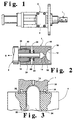
- End cap forming die 1 in accordance with the present invention is illustrated.
- End cap forming die 1 is connected to a hydraulic cylinder assembly 2 that is used to reciprocate a plunger in end cap forming die 1.
- end cap forming die is used in connection with an extrusion die (designated hereinafter by reference number 4).
- Hydraulic cylinder assembly 2 is moved in and out of a working position with respect to the extrusion die by a separate hydraulic cylinder assembly (not shown) that is connected to a mounting plate 3.
- end cap forming die is provided with a body 10 having an end cap forming cavity 12 of hemispherical shape to form the end cap.
- the tube during extrusion moves under the pressure of extrusion in a direction indicated by arrow head "A".
- ceramic material is thereby extruded or forced into end cap forming cavity 12 to assume the hemispherical shape thereof.
- Body 10 is also provided with a backfill reservoir 14 of cylindrical configuration and a passageway 16 communicating between backfill reservoir 14 and end cap forming cavity 12.
- a backfill reservoir 14 of cylindrical configuration and a passageway 16 communicating between backfill reservoir 14 and end cap forming cavity 12.
- the ceramic material is thereby also forced by the forward travel of the extrusion through passageway 16 and into backfill cavity 14.
- the ceramic material within backfill reservoir 14 is forced back through passageway 16 and into end cap forming cavity 12 to compact the ceramic material so that the ceramic material has a substantially uniform density.
- the substantially uniform density alleviates the type of defects that are caused by discontinuities within the extrusion produced by the spider support for the mandrel contained within the extrusion die.
- a plunger 18 in the form of an elongated cylinder projects into backfill reservoir 14 and is reciprocated by hydraulic cylinder assembly 2.
- Hydraulic cylinder assembly 2 is provided with a threaded fitting 20 that is threadably received within a threaded end bore 22 of body 10, thereby, to threadably connect body 10 to hydraulic cylinder assembly 2.
- a pair of nylon wipers 24 and 26 are preferably provided to prevent ceramic material from being drawn into hydraulic cylinder assembly 2 during reciprocation of plunger 18.
- end cap forming cavity 12, passageway 16, and backfill reservoir 14 are all coaxial to facilitate the action and connection of hydraulic cylinder assembly 2 to end cap forming die 1.
- end cap forming cavity 12, passageway 16, and backfill reservoir 14 are all coaxial to facilitate the action and connection of hydraulic cylinder assembly 2 to end cap forming die 1.
- other configurations are possible.
- ports 28 and 30 that communicate with the interior of backfill reservoir 14.
- plunger 18 is in a position that it would occupy after having forced ceramic material from backfill reservoir 14 into end cap forming, cavity 12.
- plunger 18 is retracted by moving in the direction indicated by arrowhead "A”.
- ports 28 and 30 are uncovered and ceramic material and air flows out of body 10.
- plunger 18 is reciprocated in a direction opposite to arrowhead "A" to also cover ports 28 and 30, thereby to prevent the escape of ceramic material from body 10.
- a potential alternative embodiment is to continue the extrusion during the backfill operation to further compact the material.
- ports 28 and 30 could be connected to a vacuum pump to remove the air within ceramic forming material located within backfill reservoir 14. In such case, provision could be made for discharging residual ceramic material within backfill reservoir 14.
- a still further embodiment, not preferred, would be to backfill the entire amount of ceramic material forced into backfill cavity 14 without any provision for the escape of ceramic material or air.
- end cap forming die 1 is illustrated in its operating position against an extrusion die 4 of known configuration.
- Extrusion die 4 has a central passageway 32 and a mandrel 34. During extrusion, ceramic material is forced between mandrel 34 and passageway 32 to assume a tubular shape.
- a locating rib 36 of annular configuration is provided in order to assure that end cap forming die 1 is positioned correctly with respect to extrusion die 4, a locating rib 36 of annular configuration is provided.
- Body portion 10 of extrusion die 1 is provided with an annular groove 38 that contacts the edge of rib 36 so as to be centered with respect to extrusion die 4.
- end cap forming die 1 is removed from extrusion die 4 and extrusion of the ceramic tube continues.
- mandrel 34 is provided with a poppet valve and an air passage to allow for the passage of air.
- passageway 16 can have a diameter from about 2/32 inches to 4/32 inches.
- the primary extrusion pressure assuming a formable ceramic piece with a moisture content from between about 10 and about 15 percent will be between about 1800 and about 2700 psi.
- plunger 18 will exert a pressure anywhere from between about 350 psi to about 850 psi with the actuation time of plunger 18 or the time in which ceramic material is forced from backfill reservoir 14 into end cap forming cavity 12 being from between about 1 and about 10 seconds.
- alternative parameters can be determined for larger tube sizes and for different ceramic materials.
Landscapes
- Engineering & Computer Science (AREA)
- Manufacturing & Machinery (AREA)
- Chemical & Material Sciences (AREA)
- Ceramic Engineering (AREA)
- Mechanical Engineering (AREA)
- Press-Shaping Or Shaping Using Conveyers (AREA)
- Manufacturing Of Tubular Articles Or Embedded Moulded Articles (AREA)
- Moulds, Cores, Or Mandrels (AREA)
Abstract
Description
Claims (8)
- A process for forming an end cap in an end of a ceramic tube, said process comprising:positioning an end cap forming die against a tube forming die, said end cap forming die having an end cap forming cavity, a backfill reservoir, and a passageway communicating between said backfill reservoir and said end cap forming cavity;extruding said ceramic tube so that ceramic material forming said end of said ceramic tube is forced into said end cap forming cavity, through said passageway, and into said backfill reservoir; andforcing said ceramic material from said backfill reservoir back through said passageway and into said end cap forming cavity to compact said ceramic material within said end cap forming cavity so that said ceramic material forming said end cap has a substantially uniform density.
- The process of claim 1, wherein a portion of said ceramic material and air is discharged from said backfill reservoir prior to said ceramic material being forced back to said end cap forming cavity.
- The process of claim 1, wherein said extruding of said tube is suspended prior to said ceramic material being forced from said backfill reservoir.
- The process of claim 2, wherein:said back fill reservoir is elongated and has ports for discharging said ceramic material and said air;said ceramic material is forced back into said end cap forming cavity by an elongated plunger projecting into said back fill reservoir and covering said ports during the forcing of said ceramic material; andsaid elongated plunger is retracted so that said ports are uncovered during discharge of said portion of said ceramic material from said backfill reservoir.
- The process of claim 4, wherein said extruding of said tube is suspended prior to said ceramic material being forced from said backfill reservoir.
- An end cap forming die for forming an end cap in an end of a ceramic tube, said end cap forming die comprising:a body configured to be situated against a tube forming die;said body having an end cap forming cavity to form said end cap, a backfill reservoir to receive ceramic material forming said ceramic tube from said end cap forming cavity, and a passageway communicating between said end cap forming cavity and said backfill reservoir;said end cap forming cavity being positioned so that when said body is situated against said tube forming die, ceramic material forming said end of said ceramic tube is able to be forced into said end cap forming cavity, through said passageway, and into said backfill reservoir; anda plunger projecting into said backfill reservoir to force said ceramic material from said backfill reservoir back through said passageway and into said end cap forming cavity to compact said ceramic material within said end cap forming cavity so that said ceramic material forming said end cap has a substantially uniform density.
- The end cap forming die of claim 6, wherein:said back fill reservoir is elongated and has ports for discharging said ceramic material and air;said plunger is elongated and covers said ports when said ceramic material is forced back into said end cap forming cavity and retracts to uncover said ports when said ceramic material and air is discharged.
- The end cap forming die of claim 7, wherein said back fill reservoir, said passageway, and said end cap forming cavity are coaxial.
Applications Claiming Priority (4)
| Application Number | Priority Date | Filing Date | Title |
|---|---|---|---|
| US597250 | 1984-04-05 | ||
| US14781899P | 1999-08-10 | 1999-08-10 | |
| US147818P | 1999-08-10 | ||
| US09/597,250 US6558597B1 (en) | 1999-08-10 | 2000-06-20 | Process for making closed-end ceramic tubes |
Publications (2)
| Publication Number | Publication Date |
|---|---|
| EP1075916A2 true EP1075916A2 (en) | 2001-02-14 |
| EP1075916A3 EP1075916A3 (en) | 2002-04-03 |
Family
ID=26845254
Family Applications (1)
| Application Number | Title | Priority Date | Filing Date |
|---|---|---|---|
| EP00117116A Withdrawn EP1075916A3 (en) | 1999-08-10 | 2000-08-09 | Process and die for making closed-end ceramic tubes |
Country Status (9)
| Country | Link |
|---|---|
| US (1) | US6558597B1 (en) |
| EP (1) | EP1075916A3 (en) |
| JP (1) | JP2001079820A (en) |
| KR (1) | KR20010049894A (en) |
| CN (1) | CN1283541A (en) |
| AU (1) | AU5191200A (en) |
| BR (1) | BRPI0003465A8 (en) |
| CA (1) | CA2315860A1 (en) |
| MX (1) | MXPA00007748A (en) |
Cited By (6)
| Publication number | Priority date | Publication date | Assignee | Title |
|---|---|---|---|---|
| FR2929546A1 (en) * | 2008-04-03 | 2009-10-09 | Air Liquide | ELABORATION OF A CERAMIC MEMBRANE SUPPORT FROM A CERAMIC EXTRUDED TUBE HAVING A HOLE THROUGH ITS WALL |
| WO2013079252A1 (en) * | 2011-11-30 | 2013-06-06 | Robert Bosch Gmbh | Production method for a tubular fuel cell having a two-layer cap region of the support body |
| WO2015130316A1 (en) * | 2014-02-28 | 2015-09-03 | General Electric Company | Method and system for manufacturing solid electrolyte tubes |
| WO2017152913A2 (en) | 2016-03-10 | 2017-09-14 | Fraunhofer-Gesellschaft zur Förderung der angewandten Forschung e.V. | Extrusion method and extrusion device for producing a closed ceramic tube with a base |
| DE102018103594A1 (en) | 2018-02-19 | 2019-08-22 | Fraunhofer-Gesellschaft zur Förderung der angewandten Forschung e.V. | To be vented extrusion device for producing a sealed with a bottom ceramic tube |
| EP4631615A1 (en) | 2023-12-15 | 2025-10-15 | Volkswagen Ag | Method for producing a sorbent element for separating a gas and/or air moisture from a fluid phase |
Families Citing this family (6)
| Publication number | Priority date | Publication date | Assignee | Title |
|---|---|---|---|---|
| JP3945452B2 (en) * | 2003-05-30 | 2007-07-18 | 株式会社デンソー | Manufacturing method of exhaust gas purification filter |
| KR100731594B1 (en) * | 2005-12-09 | 2007-06-25 | 한국에너지기술연구원 | Mold for closed ceramic gas separation tube and manufacturing method of gas separation tube using same |
| CN102120341B (en) * | 2010-12-30 | 2012-07-25 | 上海城建市政工程(集团)有限公司 | Mould for socket end of large-diameter socket and spigot type reinforcement concrete pipe |
| CN108081439B (en) * | 2018-01-10 | 2019-12-13 | 李根芝 | hollow brick adobe preparation facilities |
| CN112827363B (en) * | 2019-11-22 | 2023-04-18 | 中国科学院青岛生物能源与过程研究所 | High-temperature sealing method for tubular ceramic oxygen permeable membrane |
| CN113927700A (en) * | 2021-12-03 | 2022-01-14 | 六安庆超建筑设计有限公司 | Stair manufacturing process of prefabricated building |
Family Cites Families (16)
| Publication number | Priority date | Publication date | Assignee | Title |
|---|---|---|---|---|
| US2599268A (en) * | 1948-01-31 | 1952-06-03 | Baumat A G | Method of producing hollow ceramic bodies |
| US2954588A (en) * | 1953-09-21 | 1960-10-04 | Owens Illinois Glass Co | Method of forming hollow plastic articles |
| US2944288A (en) * | 1957-01-28 | 1960-07-12 | Owens Illinois Glass Co | Combination plasticizer, extruder and injection cylinder with recirculation |
| US3670066A (en) * | 1969-11-10 | 1972-06-13 | Emery I Valyi | Method of compression molding a thermoplastic article with walls of variable thickness |
| DE2715852C3 (en) * | 1977-04-06 | 1980-03-13 | W. Haldenwanger Kg, 8264 Waldkraiburg | Method and device for manufacturing an oxide ceramic tube closed with a dome at the end |
| US4364783A (en) * | 1981-09-08 | 1982-12-21 | Ford Motor Company | Ultrasonic end-capping of beta"-alumina tubes |
| US4540534A (en) * | 1983-10-11 | 1985-09-10 | American Optical Corporation | Apparatus and method for injection molding lenses |
| JPS6285906A (en) * | 1985-10-09 | 1987-04-20 | 日本碍子株式会社 | Method and device for molding ceramic pipe with bottom |
| JPS63312811A (en) * | 1987-06-17 | 1988-12-21 | Ngk Insulators Ltd | Sealing of end face of ceramic tube |
| JPH0631655B2 (en) * | 1987-06-24 | 1994-04-27 | 日本碍子株式会社 | Ceramic double structure tube with one end sealed and method of manufacturing the same |
| JPH01225506A (en) * | 1988-03-04 | 1989-09-08 | Ngk Insulators Ltd | Manufacture of bag cylindrical tube and core bar structure used therefor |
| JPH03187710A (en) * | 1989-12-18 | 1991-08-15 | Ngk Insulators Ltd | Manufacture of cylindrical tube having bottom and device therefor |
| KR960007275B1 (en) * | 1992-06-05 | 1996-05-30 | 폴리플라스틱스 가부시끼가이샤 | Injection molding method. Injection Molding Molds and Injection Molded Objects |
| US5346659A (en) * | 1992-11-23 | 1994-09-13 | S. C. Johnson & Son, Inc. | Method for producing a weld-line free injection molded plastic container body portion |
| DE19531709A1 (en) * | 1995-08-30 | 1997-03-06 | Battenfeld Gmbh | Method and device for manufacturing plastic objects |
| US5993985A (en) * | 1998-04-09 | 1999-11-30 | Siemens Westinghouse Power Corporation | Fuel cell tubes and method of making same |
-
2000
- 2000-06-20 US US09/597,250 patent/US6558597B1/en not_active Expired - Lifetime
- 2000-07-26 KR KR1020000043150A patent/KR20010049894A/en not_active Withdrawn
- 2000-08-08 MX MXPA00007748A patent/MXPA00007748A/en unknown
- 2000-08-09 EP EP00117116A patent/EP1075916A3/en not_active Withdrawn
- 2000-08-09 CN CN00122753A patent/CN1283541A/en active Pending
- 2000-08-09 CA CA002315860A patent/CA2315860A1/en not_active Abandoned
- 2000-08-09 JP JP2000240899A patent/JP2001079820A/en not_active Withdrawn
- 2000-08-09 BR BRPI0003465A patent/BRPI0003465A8/en unknown
- 2000-08-09 AU AU51912/00A patent/AU5191200A/en not_active Abandoned
Cited By (12)
| Publication number | Priority date | Publication date | Assignee | Title |
|---|---|---|---|---|
| FR2929546A1 (en) * | 2008-04-03 | 2009-10-09 | Air Liquide | ELABORATION OF A CERAMIC MEMBRANE SUPPORT FROM A CERAMIC EXTRUDED TUBE HAVING A HOLE THROUGH ITS WALL |
| WO2009125146A1 (en) * | 2008-04-03 | 2009-10-15 | L'air Liquide Societe Anonyme Pour L'etude Et L'exploitation Des Procedes Georges Claude | Production of a supporting member for a ceramic membrane using an extruded ceramic tube having a hole through the wall thereof |
| WO2013079252A1 (en) * | 2011-11-30 | 2013-06-06 | Robert Bosch Gmbh | Production method for a tubular fuel cell having a two-layer cap region of the support body |
| US9425466B2 (en) | 2011-11-30 | 2016-08-23 | Robert Bosch Gmbh | Production method for a tubular fuel cell having a two-layer cap region of the support body |
| WO2015130316A1 (en) * | 2014-02-28 | 2015-09-03 | General Electric Company | Method and system for manufacturing solid electrolyte tubes |
| WO2017152913A2 (en) | 2016-03-10 | 2017-09-14 | Fraunhofer-Gesellschaft zur Förderung der angewandten Forschung e.V. | Extrusion method and extrusion device for producing a closed ceramic tube with a base |
| DE102016104387A1 (en) | 2016-03-10 | 2017-09-14 | Fraunhofer-Gesellschaft zur Förderung der angewandten Forschung e.V. | Extrusion method and extrusion device for producing a bottomed ceramic tube |
| DE102016104387B4 (en) * | 2016-03-10 | 2020-11-26 | Fraunhofer-Gesellschaft zur Förderung der angewandten Forschung e.V. | Extrusion process and extrusion device for the production of a ceramic tube closed with a bottom |
| DE102018103594A1 (en) | 2018-02-19 | 2019-08-22 | Fraunhofer-Gesellschaft zur Förderung der angewandten Forschung e.V. | To be vented extrusion device for producing a sealed with a bottom ceramic tube |
| WO2019158164A1 (en) | 2018-02-19 | 2019-08-22 | Fraunhofer-Gesellschaft zur Förderung der angewandten Forschung e. V. | Extrusion device that is to be ventilated for producing a ceramic tube closed with a base |
| DE102018103594B4 (en) | 2018-02-19 | 2019-10-24 | Fraunhofer-Gesellschaft zur Förderung der angewandten Forschung e.V. | To be vented extrusion device for producing a sealed with a bottom ceramic tube |
| EP4631615A1 (en) | 2023-12-15 | 2025-10-15 | Volkswagen Ag | Method for producing a sorbent element for separating a gas and/or air moisture from a fluid phase |
Also Published As
| Publication number | Publication date |
|---|---|
| CA2315860A1 (en) | 2001-02-10 |
| JP2001079820A (en) | 2001-03-27 |
| EP1075916A3 (en) | 2002-04-03 |
| KR20010049894A (en) | 2001-06-15 |
| CN1283541A (en) | 2001-02-14 |
| AU5191200A (en) | 2001-02-15 |
| US6558597B1 (en) | 2003-05-06 |
| MXPA00007748A (en) | 2002-04-24 |
| BRPI0003465A8 (en) | 2019-01-15 |
Similar Documents
| Publication | Publication Date | Title |
|---|---|---|
| US6558597B1 (en) | Process for making closed-end ceramic tubes | |
| US4097977A (en) | Method to attach the center electrode into a ceramic insulator body of spark plugs | |
| EP0315208A2 (en) | Process for making ceramic bodies with open channels | |
| DE69915422T2 (en) | Process for the production of complex shaped hollow ceramic bodies | |
| JPS6195903A (en) | Method and device for compression-molding body in balanced manner from fine particle material | |
| US3454997A (en) | Ceramic molding apparatus | |
| CA2531904A1 (en) | Apparatus, method and core for molding a ceramic discharge vessel and removing the core | |
| US4384840A (en) | Apparatus for molding tubular parts by isostatic compression | |
| US5236021A (en) | Powder filling apparatus | |
| FI80222C (en) | FOERFARANDE FOER FRAMSTAELLNING AV EN NIT FOER EN FAST DUBB RESPEKTIVA HOLKDUBB OCH ANLAEGGNING FOER TILLAEMPNING AV FOERFARANDET. | |
| JP2009259775A (en) | Insulator for spark plug and method of manufacturing spark plug | |
| EP2570244A1 (en) | Mask for sealing honeycomb structure, and sealing method for honeycomb structure using same | |
| US6540852B1 (en) | Apparatus and method for manufacturing gaskets | |
| JPH0437762B2 (en) | ||
| US3608026A (en) | Method of manufacturing rods or tubes from powder | |
| JPH04351859A (en) | Electrolyte holder and manufacture thereof | |
| US3465075A (en) | Method for making a monolithic clay fitting | |
| US5178808A (en) | End seal manufacture for ceramic arc tubes | |
| JPS5939499A (en) | Compacting method of green compact | |
| JP2000326100A (en) | Molding method of compact having inclined surface | |
| EP0053140A1 (en) | Method for manufacturing tubes | |
| US4440706A (en) | Isostatic molding of two-terminal ceramic insulator | |
| JPS5938080B2 (en) | Pressurizing device for solid powder ring housed in a cylinder with a bottom | |
| CN1369368A (en) | Powder Pressuring tool | |
| JP2803645B2 (en) | Powder molding jig and method for producing powder compact |
Legal Events
| Date | Code | Title | Description |
|---|---|---|---|
| PUAI | Public reference made under article 153(3) epc to a published international application that has entered the european phase |
Free format text: ORIGINAL CODE: 0009012 |
|
| AK | Designated contracting states |
Kind code of ref document: A2 Designated state(s): AT BE CH CY DE DK ES FI FR GB GR IE IT LI LU MC NL PT SE |
|
| AX | Request for extension of the european patent |
Free format text: AL;LT;LV;MK;RO;SI |
|
| PUAL | Search report despatched |
Free format text: ORIGINAL CODE: 0009013 |
|
| AK | Designated contracting states |
Kind code of ref document: A3 Designated state(s): AT BE CH CY DE DK ES FI FR GB GR IE IT LI LU MC NL PT SE |
|
| AX | Request for extension of the european patent |
Free format text: AL;LT;LV;MK;RO;SI |
|
| STAA | Information on the status of an ep patent application or granted ep patent |
Free format text: STATUS: THE APPLICATION HAS BEEN WITHDRAWN |
|
| 17P | Request for examination filed |
Effective date: 20020422 |
|
| 18W | Application withdrawn |
Withdrawal date: 20020507 |