EP1075096A2 - Verfahren und Vorrichtung zur Verzerrungskompensation in einem verstärkten Lichtwellenübertragungssystem - Google Patents
Verfahren und Vorrichtung zur Verzerrungskompensation in einem verstärkten Lichtwellenübertragungssystem Download PDFInfo
- Publication number
- EP1075096A2 EP1075096A2 EP00304801A EP00304801A EP1075096A2 EP 1075096 A2 EP1075096 A2 EP 1075096A2 EP 00304801 A EP00304801 A EP 00304801A EP 00304801 A EP00304801 A EP 00304801A EP 1075096 A2 EP1075096 A2 EP 1075096A2
- Authority
- EP
- European Patent Office
- Prior art keywords
- optical
- gain
- channel
- power level
- channels
- Prior art date
- Legal status (The legal status is an assumption and is not a legal conclusion. Google has not performed a legal analysis and makes no representation as to the accuracy of the status listed.)
- Withdrawn
Links
- 238000004891 communication Methods 0.000 title claims abstract description 23
- 238000000034 method Methods 0.000 title claims description 23
- 230000003287 optical effect Effects 0.000 claims abstract description 189
- 230000004044 response Effects 0.000 claims abstract description 8
- 239000004065 semiconductor Substances 0.000 claims description 47
- 238000001228 spectrum Methods 0.000 claims description 23
- 230000008859 change Effects 0.000 claims description 10
- 230000007423 decrease Effects 0.000 claims description 5
- 230000006735 deficit Effects 0.000 claims description 5
- 230000003321 amplification Effects 0.000 claims description 3
- 238000003199 nucleic acid amplification method Methods 0.000 claims description 3
- 239000000835 fiber Substances 0.000 description 20
- 230000005540 biological transmission Effects 0.000 description 19
- 230000000694 effects Effects 0.000 description 10
- 238000001514 detection method Methods 0.000 description 7
- 239000006185 dispersion Substances 0.000 description 6
- 238000005259 measurement Methods 0.000 description 6
- 230000001419 dependent effect Effects 0.000 description 5
- 238000010586 diagram Methods 0.000 description 5
- 230000006870 function Effects 0.000 description 5
- 230000007704 transition Effects 0.000 description 5
- 238000002474 experimental method Methods 0.000 description 4
- 239000013307 optical fiber Substances 0.000 description 3
- 239000000243 solution Substances 0.000 description 3
- 229910052691 Erbium Inorganic materials 0.000 description 2
- 230000000295 complement effect Effects 0.000 description 2
- 230000000593 degrading effect Effects 0.000 description 2
- 238000005516 engineering process Methods 0.000 description 2
- UYAHIZSMUZPPFV-UHFFFAOYSA-N erbium Chemical compound [Er] UYAHIZSMUZPPFV-UHFFFAOYSA-N 0.000 description 2
- 230000006872 improvement Effects 0.000 description 2
- 238000002347 injection Methods 0.000 description 2
- 239000007924 injection Substances 0.000 description 2
- 230000006855 networking Effects 0.000 description 2
- 238000005086 pumping Methods 0.000 description 2
- 229910003327 LiNbO3 Inorganic materials 0.000 description 1
- 230000008901 benefit Effects 0.000 description 1
- 230000015556 catabolic process Effects 0.000 description 1
- 239000002131 composite material Substances 0.000 description 1
- 230000008878 coupling Effects 0.000 description 1
- 238000010168 coupling process Methods 0.000 description 1
- 238000005859 coupling reaction Methods 0.000 description 1
- 230000003247 decreasing effect Effects 0.000 description 1
- 238000006731 degradation reaction Methods 0.000 description 1
- 238000013461 design Methods 0.000 description 1
- 230000004399 eye closure Effects 0.000 description 1
- 230000009931 harmful effect Effects 0.000 description 1
- 239000000463 material Substances 0.000 description 1
- 230000007246 mechanism Effects 0.000 description 1
- 238000012544 monitoring process Methods 0.000 description 1
- 230000009022 nonlinear effect Effects 0.000 description 1
- 230000010287 polarization Effects 0.000 description 1
- 230000009467 reduction Effects 0.000 description 1
- 238000012552 review Methods 0.000 description 1
- 229920006395 saturated elastomer Polymers 0.000 description 1
- 230000008054 signal transmission Effects 0.000 description 1
- 230000000007 visual effect Effects 0.000 description 1
Images


Classifications
-
- H—ELECTRICITY
- H04—ELECTRIC COMMUNICATION TECHNIQUE
- H04B—TRANSMISSION
- H04B10/00—Transmission systems employing electromagnetic waves other than radio-waves, e.g. infrared, visible or ultraviolet light, or employing corpuscular radiation, e.g. quantum communication
- H04B10/29—Repeaters
- H04B10/291—Repeaters in which processing or amplification is carried out without conversion of the main signal from optical form
- H04B10/293—Signal power control
- H04B10/294—Signal power control in a multiwavelength system, e.g. gain equalisation
- H04B10/296—Transient power control, e.g. due to channel add/drop or rapid fluctuations in the input power
Definitions
- the invention relates generally to optical amplifiers and, more particularly, to lightwave systems and networks utilizing such amplifiers.
- Optical amplifiers are commonly used in lightwave communication systems as in-line amplifiers for boosting signal levels to compensate for losses in a transmission path, as power amplifiers for increasing transmitter power, and as pre-amplifiers for boosting signal levels before receivers.
- WDM wavelength division multiplexed
- Erbium-doped fiber amplifiers are predominantly used in current WDM communication systems because of their gain characteristics and ease of coupling with optical fiber. Erbium-doped fiber amplifiers are particularly desirable for intensity modulated digital optical communication systems, wherein the light intensity of signal channels is modulated to represent the "1"s and "0"s of digital data. In particular, slow gain dynamics allow erbium-doped fiber amplifiers to provide constant gain to all signal channels in a WDM system regardless of bit transitions in the intensity modulated bit patterns. However, despite their usefulness in long haul transmission applications, the disadvantages of erbium-doped fiber amplifiers are well known.
- erbium-doped fiber amplifiers are expensive and, as a result, do not provide the most cost effective solution for applications such as metropolitan optical networking and the like.
- erbium-doped fiber amplifiers have a relatively narrow usable gain bandwidth which will become more of a problem in emerging long haul systems which have higher channel counts and which will use new optical fiber having a wider usable bandwidth.
- semiconductor optical amplifiers are comparatively inexpensive, have a large gain bandwidth, and can be easily integrated with other devices.
- semiconductor optical amplifiers have several limitations which have limited their use in optical communication systems to date.
- the fast gain dynamics and nonlinear gain characteristics of semiconductor optical amplifiers can be problematic. For example, gain changes quickly as input power changes and is not constant for the modulation speed of current communication systems, thus resulting in problems such as inter-modal distortion and saturation-induced crosstalk, i.e., cross-saturation.
- cross-saturation results when intensity modulation in one channel leads to modulation of the gain available for other channels.
- the gain of a specific channel is saturated not only by its own power, but also by the power of the other channels in the system.
- Cross-saturation is particularly problematic in intensity modulated systems because the channel power changes with time depending on the bit pattern.
- the signal gain of one channel then changes from bit to bit, and the change depends on the bit patterns of the other channels.
- gain fluctuations can result in detection errors which degrade overall bit error rate performance.
- Gain control schemes such as feedforward or feedback gain control loops, gain clamping, and pump light injection schemes, have been proposed for reducing the effects of inter-modal distortion and cross-saturation. See, e.g., U.S. Patent No. 5,017,885, entitled “Optical Amplifier with Reduced Nonlinearity” , issued May 21, 1991 to A. Saleh, U.S. Patent No. 5,576,881, entitled “Multi-Frequency Optical Signal Source Having Reduced Distortion and Crosstalk” , issued November 19, 1996 to Doerr et al., Simon et al., "Travelling Wave Semiconductor Optical Amplifier with Reduced Nonlinear Distortions” , Electronics Letters, vol. 30, no.
- inter-modal distortion and cross-saturation may be reduced by operating optical amplifiers in the small-signal region, i.e., unsaturated region.
- small-signal region i.e., unsaturated region.
- WDM systems typically operate in the saturation region because of the high output power needed for wide dynamic range and high signal to noise ratios. Accordingly, inter-modal distortion and cross-saturation are still a problem for systems having optical amplifiers operating in the saturation region.
- Distortion and crosstalk that occurs when operating optical amplifiers in saturation is substantially reduced according to the principles of the invention by passively compensating for gain variations caused by changes in input power to the optical amplifiers. More specifically, in an optical communication system having one or more optical amplifiers, passive gain control is achieved by supplying at least one optical channel in addition to the other traffic-carrying optical channels, wherein the additional optical channel absorbs or otherwise receives most of the gain variations while the traffic-carrying channels experience less.
- the additional optical channel in one exemplary embodiment is assigned a wavelength at or near the gain peak region where the gain variations are at a maximum.
- the power level in the additional optical channel rises and falls in response to changes in power levels of the traffic-carrying channels.
- the additional optical channel serves as a "reservoir" channel that compensates for gain variations caused by changes in input power to the optical amplifier.
- a wavelength division multiplexed (WDM) signal having a plurality of optical channels of respective wavelengths is amplified by one or more semiconductor optical amplifiers in a WDM system.
- a reservoir channel is inserted prior to the first semiconductor optical amplifier at a wavelength that is located at or near the point of maximum gain variation, e.g., typically the shorter wavelength region in the gain spectrum of the semiconductor optical amplifiers.
- the gain variations in the semiconductor optical amplifiers will be highest where the reservoir channel is located.
- the reservoir channel will experience the highest amount of gain variation and, as a result, will passively compensate for the distortion and crosstalk that would otherwise occur in the traffic-carrying optical channels.
- WDM wavelength division multiplexed system
- the principles of the invention may also be employed in conjunction with other types of optical communication systems and other types of optical amplifiers.
- the principles of the invention can be applied to single channel optical communication systems and also to systems comprising other types of optical amplifiers having gain dynamics that give rise to the aforementioned problems.
- the illustrative embodiments of the invention are described with reference to digital communications in which data is transmitted using bits "0" and "1", it will be appreciated that the inventive aspects are also applicable to other coding and modulation schemes. Accordingly, the embodiments shown and described herein are only meant to be illustrative and not limiting.
- optical amplifiers used for in-line amplification in WDM systems typically operate in the saturation region due to pumping efficiency and system considerations. In the saturation region, the output power of the amplifier is substantially fixed for a certain range of input power variations. As a result, the gain of the amplifier does not remain constant with the changes in input power.
- the output power of the amplifier must also be sufficiently high so that the signal to noise ratio at the receiver is high enough to permit accurate detection of the bit patterns transmitted in the intensity modulated signal.
- FIG. 1 is an eye diagram of a signal channel wherein the output power, P OUT , exhibits inter-modal distortion. More specifically, power level 101 represents a steady state power level for a "0" bit and power level 102 represents a steady state power level of a "1" bit in the channel.
- transition point 103 When a transition from a "0" to "1" occurs in the transmitted bit pattern, represented here as transition point 103, the power level of the "1" bit actually exceeds the steady state value 102 for a certain period of time, thus resulting in gain fluctuations in the amplified signal. Consequently, this type of nonlinear distortion, which is dependent on the intensity modulation within the signal channel, can cause problems in the detection of bits, thus degrading the overall bit error rate performance of the system.
- FIG. 2 is an eye diagram for one of the signal channels in a 2-channel system.
- the output power P OUT in a signal channel depends on the state of the other channels through cross-saturation, which is the so-called crosstalk effect in WDM systems.
- the output power P OUT in one signal channel is affected by intensity modulation in the other channel in the system and will vary at random since each channel is independently modulated.
- power level 201 represents a power level for a "0" bit
- power level 202 represents a range of power levels for a "1" bit in the channel.
- the power level of a "1" bit in the channel will vary according to the power level in the other channel of the system.
- slow gain dynamics of the erbium-doped fiber amplifiers provide an advantage for modulation speeds of interest because the amplifier does not "respond" to the transitions in bits of "1"s and "0"s in the optical channels. Consequently, the erbium-doped fiber amplifier only sees the average power and therefore provides constant gain to the signal channels. As such, the gain of an erbium-doped fiber amplifier exhibits a linear characteristic such that inter-modal distortion and cross-saturation are not significant problems.
- the gain dynamics of a semiconductor optical amplifier are much faster than that of an erbium-doped fiber amplifier.
- the gain of a semiconductor optical amplifier changes rapidly as the input power changes and, as a result, the gain is not constant for the modulation speed of current communication systems.
- the gain of a semiconductor optical amplifier exhibits a nonlinear characteristic which causes the aforementioned problems of inter-modal distortion and cross-saturation which, in turn, can cause errors in the detection of bits transmitted within the channels of an optical communication system. Consequently, we have identified a need to solve the aforementioned problems so that semiconductor optical amplifiers can become a suitable alternative for single channel and WDM systems instead of the more expensive and bandwidth-limited erbium-doped fiber amplifiers.
- a passive control technique is provided so that semiconductor optical amplifiers can be effectively used as in-line amplifiers in wavelength division multiplexed systems even in the presence of inter-modal distortion and cross-saturation. More specifically, we have discovered that substantially error-free transmission can be achieved in a WDM system employing semiconductor optical amplifiers by using an optical channel of a particular wavelength to perform a "reservoir" type function. This reservoir channel is used to share power along with the other optical channels in the WDM signal in response to input power changes to the amplifier and, by doing so, effectively regulates the gain variations that occur in a semiconductor optical amplifier as a result of inter-modal distortion and cross-saturation.
- the reservoir channel compensates for the aforementioned gain variations that occur as a result of changes in input power among the traffic-carrying optical channels, bit pattern transitions, crosstalk from other optical channels, and the like. Resulting gain variations in the semiconductor optical amplifier will therefore have less effect on the other optical channels in the WDM signal which carry traffic.
- FIG. 3 shows the gain spectra, i.e., gain as a function of wavelength, at different carrier density levels n for a typical semiconductor gain medium. For simplicity of illustration and explanation, only two carrier density levels n are shown and described. As shown, the intrinsic gain of a semiconductor optical amplifier is not flat, so the gain peaks at a center wavelength and goes down on both sides of the gain peak.
- FIG. 3 shows two exemplary gain curves 301 and 302 corresponding to carrier density n 1 and n 2 , respectively, where n 1 > n 2 .
- a higher carrier density n 1 generates higher gain as compared to a lower carrier density n 2 .
- carrier density n changes with changes in input optical power P IN , assuming the pump current is fixed.
- the gain shape takes on different curves, e.g., 301 and 302 as shown in FIG. 3, depending on the input power and gain dynamics.
- the gain varies between curves 301 and 302.
- these gain variations ⁇ g can result in the aforementioned problems of signal distortion and inter-channel or saturation-induced crosstalk. Gain variations are especially problematic for WDM systems in which input power P IN is typically not constant among the multiple adjacent wavelength channels.
- gain variations ⁇ g 0 and ⁇ g 1 represent the gain shifts between gain curves 301 and 302 measured at wavelengths ⁇ 0 and ⁇ 1 respectively. It is clear from FIG. 3 that the gain variation is larger near the gain peak, i.e., highest point on the gain curves, such that ⁇ g 0 > ⁇ g 1 . Moreover, FIG. 3 also illustrates how the gain variations as measured between gain curves 301 and 302 are larger in the shorter wavelength region than in the longer wavelength region, e.g., higher wavelengths. In particular, the distances between gain curves 301 and 302 are greater for the wavelengths on the left side of the gain peak than for wavelengths on the right side of the gain peak.
- ⁇ 1 > ⁇ 0 i.e., ⁇ 0 is the shorter wavelength and ⁇ 1 is the longer wavelength
- the gain variation is larger towards the shorter wavelength ⁇ 0 , which is also nearer to the gain peak.
- gain saturation is wavelength dependent, wherein saturation is stronger for wavelengths around the gain peak and progressively weaker for wavelengths located further away from the gain peak.
- distortion and saturation-induced crosstalk are also wavelength dependent.
- the wavelength of the reservoir channel is therefore selected such that the power level of the reservoir channel varies in response to a change in power level of one or more of the other optical channels in the WDM signal.
- optical channels having wavelengths near the gain peak of the semiconductor optical amplifier i.e., the high gain region, tend to suffer the highest gain variations and are most susceptible to gain-induced crosstalk. Consequently, we have found the reservoir channel to be most effective when located in the shorter wavelength region at or near the point of maximum gain variation in the gain spectrum, e.g., at or near the gain peak. Accordingly, it is desirable to locate the traffic-carrying optical channels in the longer wavelength region.
- the reservoir channel can be assigned at or near the region having a large amount of gain variation, e.g., wavelength ⁇ 0
- the traffic-carrying channels can be assigned wavelengths further from the gain peak, e.g., wavelength ⁇ 1 and so on.
- the wavelength assignments will also depend on where the channels can still experience sufficient gain as required in the system.
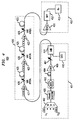
- wavelength division multiplexed system 400 includes a transmitter portion 401, a transmission section 420, and a receiver portion 450.
- ECLs external cavity lasers
- the data rate was 2.5 Gb/s for each of the channels with a pseudo-random bit sequence (PRBS) of 2 31 -1.
- PRBS pseudo-random bit sequence
- Polarization selector 405, erbium doped fiber amplifier 406, and optical attenuator 407 were also used in transmitter portion 401 according to well-known techniques and principles of operation.
- the reservoir channel was added using a laser source, e.g., distributed feedback laser (DFB) 410, and a coupler, e.g., 3dB coupler 411, before the first semiconductor optical amplifier 421 in transmission section 420.
- a laser source e.g., distributed feedback laser (DFB) 410
- a coupler e.g., 3dB coupler 411
- the use of distributed feedback laser 410 and 3dB coupler 411 are only meant to be illustrative and not limiting in any way. Accordingly, other means for transmitting an optical channel, e.g., other well-known laser sources and couplers, will be apparent to those skilled in the art and are contemplated by the teachings herein.
- In transmission section 420 three spans of standard single mode transmission fiber 425 are each preceded with a respective semiconductor optical amplifier 421-423. Commercially available single stage semiconductor optical amplifiers without gain control were used for the experiment. Other type semiconductor optical amplifiers may also be used in conjunction with the teachings
- the small signal gain of semiconductor optical amplifiers 421-423 was approximately 20 dB when pumped at 400 mA. For each of amplifiers 421-423 operating under strong saturation in this experiment, the total input power was maintained at about -3 dBm, the gain was 15 dB (which is about 5 dB below the small-signal gain), and the output power was about 12 dBm.
- Each transmission fiber span 425 was between 41 and 42 km in length with around 9 dB loss per span.
- a variable attenuator 426 was placed after each semiconductor optical amplifier 421-423, respectively, to achieve a total span loss of about 15 dB.
- erbium doped fiber amplifier 451 was used as a pre-amplifier.
- Band-pass-filter 452 was used to select one channel at a time for appropriate measurement, e.g., BER and eye measurement.
- Detector/receiver 453 was used to detect bits in the 32 channels.
- FIGS. 5A and 5B illustrate the wavelength assignments of reservoir channel 501, shown here as ⁇ R , and traffic-carrying optical channels 502 of the WDM signal, shown here as ⁇ 1 - ⁇ 32 , which were used in the experimental configuration shown in FIG. 4. More specifically, the power spectrum at the input end of a transmission section (i.e., prior to semiconductor optical amplifier 421) is shown in FIG. 5A and the power spectrum at the output end of the transmission section (e.g., after semiconductor optical amplifier 423) is shown in FIG. 5B.
- Reservoir channel 501 is located in the signal band or gain spectrum of the optical amplifier to reduce gain variations. As previously indicated, reservoir channel 501 should have a wavelength in the gain spectrum where gain variations or fluctuations are at or near a maximum to be most effective.
- reservoir channel 501 should be located at the shorter wavelength region of the signal spectrum instead of the longer wavelength region.
- the wavelength for reservoir channel 501 was selected to be about 1531.78 nm, while the traffic carrying optical channels 502 were in the wavelength range of 1534.95 nm to 1559.36. It should be noted that this wavelength assignment is only meant to be illustrative and not limiting in any way.
- the Initial power level, e.g., launched power, of reservoir channel 501 is also an important consideration.
- the initial power level of reservoir channel 501 should be higher than that of the traffic-carrying optical channels 502 because reservoir channel 501 must be able to share power with the other optical channels according to changes in input power.
- other well-known factors may need to be considered in selecting an appropriate power level for reservoir channel 501. For example, if the power level for reservoir channel 501 is too high, then other system impairments, e.g., power-dependent optical impairments such as Stimulated Brillioun Scattering (SBS) and the like, may degrade system performance.
- SBS Stimulated Brillioun Scattering
- the power in reservoir channel 501 is approximately 12 dB to 13 dB higher than that of a traffic-carrying optical channel 502 at the input, e.g., approximately four times as much power in reservoir channel 501 than in a traffic carrying optical channel 502.
- reservoir channel 501 serves as a passive compensation mechanism by which gain variations in traffic-carrying optical channels can be substantially reduced. More specifically, by selecting an appropriate wavelength for reservoir channel 501 around the gain peak region of the amplifier and an appropriate power level, gain variations resulting from fluctuations in power at the input to the optical amplifier (e.g., by adding or dropping traffic-carrying channels, changes in bit patterns in the channels, etc.) will be suppressed. For example, when total input power to the amplifier decreases, e.g., lower than an expected level, the output power in the surviving traffic-carrying channels would typically fluctuate (i.e., increase) as a result of gain variations within the amplifier.
- reservoir channel 501 is a passive compensation channel for sharing power with the traffic-carrying channels as the power levels of the traffic-carrying channels fluctuate.
- the power level of the reservoir channel is initially four times that of a traffic-carrying channel, e.g., approximately 12-13dB higher. So, for this example, the reservoir channel initially has approximately the same power as all four traffic-carrying channels combined.
- the power level of the reservoir channel rises to compensate for one less traffic-carrying channel being available (e.g., the channel now carrying a "0" bit) to otherwise share the power.
- the power level of the reservoir channel rises to compensate for two less traffic-carrying channels being available to otherwise share the power.
- the power level of the reservoir channel rises to compensate for three less traffic-carrying channels being available to otherwise share the power.
- the sharing of power in the reservoir channel reduces the magnitude of the power fluctuations in the traffic-carrying channels.
- the fluctuations without the reservoir channel are much steeper, e.g., on the order of 1 to 1/2 to 1/3, and so on.
- the fluctuations are much more gradual in the traffic-carrying channels, e.g., 1/5 to 1/6 to 1/7 and so on.
- the reservoir channel is supplied along with the traffic-carrying channels at the input to the amplifier, the reservoir channel passively compensates for power fluctuations in the other optical channels by sharing power based on input power changes.
- the principles of the invention can be applied without any active feedback or feedforward circuitry as used in the active control schemes of the prior art. Accordingly, the reservoir channel is a low cost, less complex, but highly effective scheme in compensating for input power fluctuations as compared to prior arrangements.
- the reservoir channel can be either unmodulated or modulated to carry out some additional functions as desired.
- the reservoir channel may be modulated to perform a particular function, e.g., compensating for optical nonlinearities such as power-dependent Stimulated Brillioun Scattering (SBS).
- SBS power-dependent Stimulated Brillioun Scattering
- the reservoir channel could also be used as a telemetry channel for carrying control or supervisory information to manage the system or components in the system.
- Other uses of a modulated reservoir channel will be apparent to those skilled in the art.
- FIGS. 6A-6B show the eye-diagrams for a representative channel. As shown in FIG. 6A, the distortion is clearly greater (e.g., more eye closure) than when using a reservoir channel as shown in FIG. 6B.
- FIG. 6B shows the eye being open for all channels at the detector when using a reservoir channel.
- bit error rate (BER) measurement data for signal transmissions in the exemplary configuration in FIG. 4 are shown in FIG. 7.
- curves 550-552 a solid line has been drawn through the various data points to serve as a visual aid.
- curve 552 represents a baseline curve for bit error rate performance for signals transmitted from transmitter portion 401 to receiver portion 450 but not passing through transmission section 420 of exemplary system 400 in FIG. 4.
- curve 552 shows bit error rate performance without the inter-modal distortion and cross-saturation effects from semiconductor optical amplifiers 421-423.
- substantially error-free transmission for all 32 channels was achieved using the reservoir channel with about a 1 dB to 2 dB penalty.
- Curve 551 illustrates an important point that, as received power increases, the BER reaches a point at which no further reduction in BER can be realized. Accordingly, a comparison between curves 550 (with reservoir channel) and 551 (without reservoir channel) clearly illustrates that BER performance can be substantially improved using the reservoir channel.
- the principles of the invention are particularly useful in WDM systems employing cascaded semiconductor optical amplifiers operated under saturation.
- power fluctuations will depend on several factors.
- One such factor is dispersion in the transmission fiber which can cause relative shifts in the bits of different signal channels, e.g., the bits in different channels may travel at different speeds causing the bits to shift relative to each other.
- dispersion in the transmission fiber which can cause relative shifts in the bits of different signal channels, e.g., the bits in different channels may travel at different speeds causing the bits to shift relative to each other.
- power fluctuations should decrease as the signals propagate further along in the system.
- systems with higher dispersion however, relative shifts in the bits of different optical channels can cause further fluctuations in the input power at downstream semiconductor optical amplifiers.
- the principles of the invention may also be used in these cascaded amplifier arrangements to control dispersion-related power fluctuations.
- the noise figure for semiconductor optical amplifiers e.g., typically 6 dB or higher
- the output power e.g., typically 15 dBm or lower
- other techniques may be used for addressing some of the other nonlinear effects of fiber-based systems, such as four-wave-mixing, self-phase-modulation, and cross-phase-modulation, to name a few.
- the principles of the invention address the saturation induced crosstalk effects which have prevented widespread use of semiconductor optical amplifiers in WDM applications. With these problems solved, the principles of the invention can therefore be readily applied to provide a low cost solution for WDM transmission, such as in metropolitan applications and the like.
- gain control schemes have been studied for erbium-doped fiber amplifiers and other types of amplifiers and lasers, such as link control and pump control. In these methods, the gain or total power is monitored and then the information is used to actively control the control channel or pump. All these schemes can still be used with semiconductor optical amplifier-based systems which employ the reservoir channel according to the principles of the invention.
- the monitoring wavelength used in these schemes should be located at or near the gain peak region (e.g., to monitor the most sensitive point).
- the control channel should also be located in the gain peak region to be most effective, e.g., to effectively alter P IN of the reservoir channel to maintain constant P OUT .
- the passive compensation provided by the reservoir channel can also complement other techniques for improving the bit error rate performance of an optically amplified system.
- the reservoir channel can be used in conjunction with the technique described in EP patent application no. 00301028.7 wherein the detection threshold level of the system is adjusted to achieve more accurate detection even in the presence of inter-modal distortion and crosstalk.
Applications Claiming Priority (4)
| Application Number | Priority Date | Filing Date | Title |
|---|---|---|---|
| US13811299P | 1999-06-07 | 1999-06-07 | |
| US138112P | 1999-06-07 | ||
| US357228 | 1999-07-20 | ||
| US09/357,228 US6671466B1 (en) | 1999-06-07 | 1999-07-20 | Distortion compensation in optically amplified lightwave communication systems |
Publications (2)
| Publication Number | Publication Date |
|---|---|
| EP1075096A2 true EP1075096A2 (de) | 2001-02-07 |
| EP1075096A3 EP1075096A3 (de) | 2001-10-10 |
Family
ID=26835874
Family Applications (1)
| Application Number | Title | Priority Date | Filing Date |
|---|---|---|---|
| EP00304801A Withdrawn EP1075096A3 (de) | 1999-06-07 | 2000-06-06 | Verfahren und Vorrichtung zur Verzerrungskompensation in einem verstärkten Lichtwellenübertragungssystem |
Country Status (4)
| Country | Link |
|---|---|
| US (1) | US6671466B1 (de) |
| EP (1) | EP1075096A3 (de) |
| CN (1) | CN1276538A (de) |
| CA (1) | CA2310305C (de) |
Families Citing this family (8)
| Publication number | Priority date | Publication date | Assignee | Title |
|---|---|---|---|---|
| JP4204693B2 (ja) * | 1999-03-31 | 2009-01-07 | 三菱電機株式会社 | 光増幅装置 |
| FR2838189B1 (fr) * | 2002-04-08 | 2004-10-15 | Cit Alcatel | Dispositif de mesure et/ou de controle dynamique de perte de puissance dans une ligne de transmission optique, et procede associe |
| JP4250400B2 (ja) * | 2002-10-18 | 2009-04-08 | 富士通株式会社 | 波長多重方法及びその装置 |
| US7881620B2 (en) * | 2005-05-04 | 2011-02-01 | Ofs Fitel, Llc | Stabilized optical fiber continuum frequency combs using post-processed highly nonlinear fibers |
| KR100824999B1 (ko) | 2006-03-22 | 2008-04-24 | 연세대학교 산학협력단 | 광송신기용 비선형 왜곡 제거장치 및 제거방법 |
| WO2019003833A1 (ja) * | 2017-06-27 | 2019-01-03 | 住友電気工業株式会社 | 光受信モジュール、光受信方法、局側装置、ponシステム、及び、光フィルタ |
| JP7363165B2 (ja) * | 2019-02-19 | 2023-10-18 | 富士フイルムビジネスイノベーション株式会社 | 半導体光増幅器、光出力装置、および距離計測装置 |
| US11575556B2 (en) * | 2020-08-28 | 2023-02-07 | Ciena Corporation | Estimation of communication system impairments using spectrally selective signal perturbations |
Citations (2)
| Publication number | Priority date | Publication date | Assignee | Title |
|---|---|---|---|---|
| WO1998027674A1 (en) * | 1996-12-17 | 1998-06-25 | Koninklijke Kpn N.V. | Optical long-distance signal transmission with optical amplification |
| FR2764141A1 (fr) * | 1997-05-29 | 1998-12-04 | Alsthom Cge Alcatel | Systeme de transmission optique a compensation dynamique de la puissance transmise |
Family Cites Families (10)
| Publication number | Priority date | Publication date | Assignee | Title |
|---|---|---|---|---|
| US5017885A (en) | 1984-05-10 | 1991-05-21 | At&T Bell Laboratories | Optical amplifier with reduced nonlinearity |
| US5050949A (en) * | 1990-06-22 | 1991-09-24 | At&T Bell Laboratories | Multi-stage optical fiber amplifier |
| JP4036489B2 (ja) | 1995-08-23 | 2008-01-23 | 富士通株式会社 | 波長多重信号を光増幅する光増幅器を制御するための方法と装置 |
| US5576881A (en) | 1995-08-29 | 1996-11-19 | Lucent Technologies Inc. | Multi-frequency optical signal source having reduced distortion and crosstalk |
| JP2871547B2 (ja) | 1995-09-08 | 1999-03-17 | 日本電気株式会社 | 光スペクトルアナライザ装置および光増幅器の制御方法 |
| US5900968A (en) | 1996-02-23 | 1999-05-04 | Lucent Technologies Inc. | Method of fast gain control in WDM optical networks |
| JPH09321740A (ja) * | 1996-05-31 | 1997-12-12 | Fujitsu Ltd | 波長分割多重のための光増幅器 |
| US5907420A (en) | 1996-09-13 | 1999-05-25 | Lucent Technologies, Inc. | System and method for mitigating cross-saturation in optically amplified networks |
| EP0946006B1 (de) * | 1998-03-26 | 2001-06-27 | Lucent Technologies Inc. | Verfahren und Vorrichtung zur Steuerung der optischen Leistung eines wellenlängenmultiplexierten übertragenen Signals |
| US6473212B1 (en) * | 1999-02-19 | 2002-10-29 | Lucent Technologies Inc. | Lightwave communication systems using semiconductor optical amplifiers |
-
1999
- 1999-07-20 US US09/357,228 patent/US6671466B1/en not_active Expired - Fee Related
-
2000
- 2000-05-30 CA CA002310305A patent/CA2310305C/en not_active Expired - Fee Related
- 2000-06-06 EP EP00304801A patent/EP1075096A3/de not_active Withdrawn
- 2000-06-07 CN CN00118107.6A patent/CN1276538A/zh active Pending
Patent Citations (2)
| Publication number | Priority date | Publication date | Assignee | Title |
|---|---|---|---|---|
| WO1998027674A1 (en) * | 1996-12-17 | 1998-06-25 | Koninklijke Kpn N.V. | Optical long-distance signal transmission with optical amplification |
| FR2764141A1 (fr) * | 1997-05-29 | 1998-12-04 | Alsthom Cge Alcatel | Systeme de transmission optique a compensation dynamique de la puissance transmise |
Non-Patent Citations (1)
| Title |
|---|
| ZHAO X ET AL: "Performance analysis of gain-clamped semiconductor optical amplifiers using different clamping schemes" CONFERENCE PROCEEDINGS. LEOS '97, 10TH ANNUAL MEETING. IEEE LASERS AND ELECTRO-OPTICS SOCIETY 1997 ANNUAL MEETING (CAT. NO.97CH36057), CONFERENCE PROCEEDINGS. LEOS '97. 10TH ANNUAL MEETING IEEE LASERS AND ELECTRO-OPTICS SOCIETY 1997 ANNUAL MEETING, S, pages 337-338 vol.1, XP002174932 1996, New York, NY, USA, IEEE, USA ISBN: 0-7803-3895-2 * |
Also Published As
| Publication number | Publication date |
|---|---|
| CA2310305C (en) | 2004-04-06 |
| US6671466B1 (en) | 2003-12-30 |
| CN1276538A (zh) | 2000-12-13 |
| EP1075096A3 (de) | 2001-10-10 |
| CA2310305A1 (en) | 2000-12-07 |
Similar Documents
| Publication | Publication Date | Title |
|---|---|---|
| US5696615A (en) | Wavelength division multiplexed optical communication systems employing uniform gain optical amplifiers | |
| US5959750A (en) | Method of upgrading transmission capacity by Raman amplification | |
| JP3155837B2 (ja) | 光伝送装置 | |
| USRE37621E1 (en) | Optical communication transmission system | |
| US6038356A (en) | Lightwave transmission system employing raman and rare-earth doped fiber amplification | |
| US6856768B2 (en) | Dynamic add/drop of channels in a linear-optical-amplifier-based wavelength-division-multiplexed system | |
| US6671466B1 (en) | Distortion compensation in optically amplified lightwave communication systems | |
| KR20050106073A (ko) | 광전송 시스템 | |
| EP1271810B1 (de) | Verfahren und Vorrichtung zur Wellenformung eines optischen Signals | |
| EP1030470B1 (de) | Lichtwellenübertragungssysteme unter Verwendung von optischen Halbleiterverstärkern | |
| Nielsen et al. | 8 x 10 Gb/s 1.3-μm unrepeatered transmission over a distance of 141 km with Raman post-and pre-amplifiers | |
| US7110680B2 (en) | Method and system for forward pumping Raman amplification in an optical network | |
| JP3877942B2 (ja) | 光通信システム動作方法及び光通信システム | |
| US6876488B1 (en) | Discrete amplification of an optical signal | |
| Sun et al. | Error-free transmission of 32× 2.5 Gb/s DWDM channels over 125 km of AllWave™ fiber using cascaded in-line Semiconductor Optical Amplifiers | |
| Delansay et al. | 2.5-Gbit/s transmission over 1086 km of standard single-mode fiber using an integrated laser Mach-Zehnder modulator | |
| US11189986B2 (en) | Low-noise Raman amplifier | |
| Banerjee et al. | Cascaded semiconductor optical amplifiers for transmission of 32 DWDM channels over 315 km | |
| US11121797B1 (en) | Optical system for compensating for signal loss | |
| US7038839B1 (en) | Optical signal amplification using multiple backward-pumping systems | |
| Srivastava et al. | Error free transmission of 64 WDM 10 Gb/s channels over 520 km of Truewave/sup TM/fiber | |
| Gabla et al. | 1111 km, two channel IM-DD transmission experiment at 2.5 Gb/s through 21 in-line erbium-doped fiber amplifiers | |
| US20030077032A1 (en) | Long distance optical transmission system for high dynamic range signals | |
| Mikkelsen et al. | Reduction of crosstalk in semiconductor optical amplifiers by amplifying dispersed WDM signals (7× 20 Gb/s) | |
| Murakami et al. | Long-haul WDM transmission with 20 Gb/s data channels using Raman assisted optical amplification |
Legal Events
| Date | Code | Title | Description |
|---|---|---|---|
| PUAI | Public reference made under article 153(3) epc to a published international application that has entered the european phase |
Free format text: ORIGINAL CODE: 0009012 |
|
| AK | Designated contracting states |
Kind code of ref document: A2 Designated state(s): AT BE CH CY DE DK ES FI FR GB GR IE IT LI LU MC NL PT SE Kind code of ref document: A2 Designated state(s): DE FR |
|
| AX | Request for extension of the european patent |
Free format text: AL;LT;LV;MK;RO;SI |
|
| PUAL | Search report despatched |
Free format text: ORIGINAL CODE: 0009013 |
|
| RIC1 | Information provided on ipc code assigned before grant |
Free format text: 7H 04B 10/17 A, 7H 01S 3/13 B |
|
| AK | Designated contracting states |
Kind code of ref document: A3 Designated state(s): AT BE CH CY DE DK ES FI FR GB GR IE IT LI LU MC NL PT SE |
|
| AX | Request for extension of the european patent |
Free format text: AL;LT;LV;MK;RO;SI |
|
| 17P | Request for examination filed |
Effective date: 20020330 |
|
| AKX | Designation fees paid |
Free format text: DE FR |
|
| 17Q | First examination report despatched |
Effective date: 20060331 |
|
| 17Q | First examination report despatched |
Effective date: 20060331 |
|
| GRAP | Despatch of communication of intention to grant a patent |
Free format text: ORIGINAL CODE: EPIDOSNIGR1 |
|
| STAA | Information on the status of an ep patent application or granted ep patent |
Free format text: STATUS: THE APPLICATION IS DEEMED TO BE WITHDRAWN |
|
| 18D | Application deemed to be withdrawn |
Effective date: 20080223 |