EP1075052A1 - Lever-type electrical connector - Google Patents
Lever-type electrical connector Download PDFInfo
- Publication number
- EP1075052A1 EP1075052A1 EP00306488A EP00306488A EP1075052A1 EP 1075052 A1 EP1075052 A1 EP 1075052A1 EP 00306488 A EP00306488 A EP 00306488A EP 00306488 A EP00306488 A EP 00306488A EP 1075052 A1 EP1075052 A1 EP 1075052A1
- Authority
- EP
- European Patent Office
- Prior art keywords
- connector
- spring
- locking
- connector housings
- housings
- Prior art date
- Legal status (The legal status is an assumption and is not a legal conclusion. Google has not performed a legal analysis and makes no representation as to the accuracy of the status listed.)
- Withdrawn
Links
- 238000000926 separation method Methods 0.000 claims abstract description 5
- 230000000452 restraining effect Effects 0.000 claims description 2
- 230000004308 accommodation Effects 0.000 description 12
- 210000000078 claw Anatomy 0.000 description 11
- 238000003780 insertion Methods 0.000 description 6
- 230000037431 insertion Effects 0.000 description 6
- 239000002184 metal Substances 0.000 description 6
- 239000000758 substrate Substances 0.000 description 4
- 238000013459 approach Methods 0.000 description 3
- 238000010276 construction Methods 0.000 description 3
- 230000005489 elastic deformation Effects 0.000 description 3
- 239000000463 material Substances 0.000 description 3
- 230000000149 penetrating effect Effects 0.000 description 3
- 229920003002 synthetic resin Polymers 0.000 description 3
- 239000000057 synthetic resin Substances 0.000 description 3
- 238000012986 modification Methods 0.000 description 2
- 230000004048 modification Effects 0.000 description 2
- 230000002093 peripheral effect Effects 0.000 description 2
- 230000015572 biosynthetic process Effects 0.000 description 1
- 230000006835 compression Effects 0.000 description 1
- 238000007906 compression Methods 0.000 description 1
- 238000001514 detection method Methods 0.000 description 1
- 238000004519 manufacturing process Methods 0.000 description 1
- 230000013011 mating Effects 0.000 description 1
- 230000035515 penetration Effects 0.000 description 1
Images








Classifications
-
- H—ELECTRICITY
- H01—ELECTRIC ELEMENTS
- H01R—ELECTRICALLY-CONDUCTIVE CONNECTIONS; STRUCTURAL ASSOCIATIONS OF A PLURALITY OF MUTUALLY-INSULATED ELECTRICAL CONNECTING ELEMENTS; COUPLING DEVICES; CURRENT COLLECTORS
- H01R13/00—Details of coupling devices of the kinds covered by groups H01R12/70 or H01R24/00 - H01R33/00
- H01R13/62—Means for facilitating engagement or disengagement of coupling parts or for holding them in engagement
- H01R13/629—Additional means for facilitating engagement or disengagement of coupling parts, e.g. aligning or guiding means, levers, gas pressure electrical locking indicators, manufacturing tolerances
- H01R13/62933—Comprising exclusively pivoting lever
- H01R13/62938—Pivoting lever comprising own camming means
-
- H—ELECTRICITY
- H01—ELECTRIC ELEMENTS
- H01R—ELECTRICALLY-CONDUCTIVE CONNECTIONS; STRUCTURAL ASSOCIATIONS OF A PLURALITY OF MUTUALLY-INSULATED ELECTRICAL CONNECTING ELEMENTS; COUPLING DEVICES; CURRENT COLLECTORS
- H01R13/00—Details of coupling devices of the kinds covered by groups H01R12/70 or H01R24/00 - H01R33/00
- H01R13/62—Means for facilitating engagement or disengagement of coupling parts or for holding them in engagement
- H01R13/629—Additional means for facilitating engagement or disengagement of coupling parts, e.g. aligning or guiding means, levers, gas pressure electrical locking indicators, manufacturing tolerances
- H01R13/62933—Comprising exclusively pivoting lever
- H01R13/62955—Pivoting lever comprising supplementary/additional locking means
-
- H—ELECTRICITY
- H01—ELECTRIC ELEMENTS
- H01R—ELECTRICALLY-CONDUCTIVE CONNECTIONS; STRUCTURAL ASSOCIATIONS OF A PLURALITY OF MUTUALLY-INSULATED ELECTRICAL CONNECTING ELEMENTS; COUPLING DEVICES; CURRENT COLLECTORS
- H01R13/00—Details of coupling devices of the kinds covered by groups H01R12/70 or H01R24/00 - H01R33/00
- H01R13/62—Means for facilitating engagement or disengagement of coupling parts or for holding them in engagement
- H01R13/629—Additional means for facilitating engagement or disengagement of coupling parts, e.g. aligning or guiding means, levers, gas pressure electrical locking indicators, manufacturing tolerances
- H01R13/633—Additional means for facilitating engagement or disengagement of coupling parts, e.g. aligning or guiding means, levers, gas pressure electrical locking indicators, manufacturing tolerances for disengagement only
- H01R13/635—Additional means for facilitating engagement or disengagement of coupling parts, e.g. aligning or guiding means, levers, gas pressure electrical locking indicators, manufacturing tolerances for disengagement only by mechanical pressure, e.g. spring force
-
- Y—GENERAL TAGGING OF NEW TECHNOLOGICAL DEVELOPMENTS; GENERAL TAGGING OF CROSS-SECTIONAL TECHNOLOGIES SPANNING OVER SEVERAL SECTIONS OF THE IPC; TECHNICAL SUBJECTS COVERED BY FORMER USPC CROSS-REFERENCE ART COLLECTIONS [XRACs] AND DIGESTS
- Y10—TECHNICAL SUBJECTS COVERED BY FORMER USPC
- Y10S—TECHNICAL SUBJECTS COVERED BY FORMER USPC CROSS-REFERENCE ART COLLECTIONS [XRACs] AND DIGESTS
- Y10S439/00—Electrical connectors
- Y10S439/923—Separation or disconnection aid
Definitions
- the present invention relates to a lever-type electrical connector, for example a connector suitable for use in a motor vehicle to connect wire bundles.
- a lever-type connector for example, a lever having a cam groove is rotatably mounted on a male housing, and a follower fitting in the cam groove is provided on a mating female housing.
- a follower fitting in the cam groove is provided on a mating female housing.
- a lever-type electrical connector having first and second connector housings adapted to be detachably fitted together in a connected position by relative movement in a fitting direction, and a lever rotatably mounted on the connector for drawing the connector housings in said fitting direction towards said connected position.
- Locking means are provided on the connector housings for locking them together in the connected position.
- Spring means are provided to act operatively between the connector housings so as to be resiliently deformed when the connector housings are being moved towards the connected position, thereby to create a force urging the connector housings in their separation direction at least during the movement of the connector housings towards the connected position.
- the lever is rotated.
- the locking means holds the fitted state. If the fitting operation is stopped before the connector housings are in the normal fitted state, the urging force of the spring means causes the connector housings to separate from each other. Irrespective of the position of the lever therefore, it is possible to securely detect whether or not the connector housings have been fitted in each other normally.
- the spring means comprises at least one spring having a front end and a rear end, the first connector housing acting upon the front end of the spring to compress it during fitting of the connector housings together, and the second connector housing has a spring holder restraining the rear end of the spring.
- the spring holder is arranged to cooperate with the locking means so that, during fitting of the connector housings together, (i) before the locking means locks the connector housings in the connected position the spring holder restrains the spring from relaxation of its compressed state, and (ii) when the locking means has locked the connector housings in the connected position the locking means releases the restraint of the spring to allow at least partial relaxation of the spring.
- the spring incorporated in the second connector housing is acted on by the first connector housing.
- the spring holder restrains the rear end of the spring.
- the spring is gradually compressed. Accordingly, if the fitting operation is stopped before the connector housings are fitted on each other normally, they are separated from each other by the spring force. The spring force is relaxed on normal fitting, and this may be detectable by the user.
- the locking means comprises cooperating members in the form of at least one locking projection provided on the first connector housing and correspondingly at least one resiliently deformable locking arm provided on the second connector housing.
- the locking projection and locking arm are arranged and shaped so that, when the connector housings are moved towards the connected position, the locking arm engages and is deflected by the locking projection and thereafter locks behind the locking projection in a latch manner.
- the locking arm when so deflected prevents the spring holder releasing the compressed state of the spring.
- the locking arm rides on the locking projection.
- the locking arm returns to its original state by its elastic or resilient deformation and is locked to the locking projection.
- the connector housings are prevented from separating from each other.
- the spring holder releases the rear end of the spring.
- the spring is released from the compressed state. Accordingly, after the connector housings are fitted in each other normally, the spring force does not act as a connector separating force.
- the locking means act to lock the connector housings together at both ends of the connector housings in their elongation direction and the spring means comprises springs likewise act on the housings at both their ends.
- one of the connector housings comprises a housing portion to receive electrical terminals and a casing which receives the housing portion, the housing portion being slidable in the casing in the direction of fitting of the connector housings to each other.
- the lever is rotatably mounted on the housing portion and has a cam surface, while the other connector housing has a cam follower which engages this cam surface during fitting of the connector housings together.
- the casing is engageable with the lever so that by its rotation the lever holds the casing and the housing portion together.
- the locking means and spring means are provided on, and act between, the casing and the other connector housing. With the connector housing portion accommodated in the casing located at the front side, this connector portion is fitted in the other connector housing. Then, the casing is pressed.
- the lever rotates.
- the connector housings are fitted to each other with a small force owing to the action of the lever.
- the casing is locked to the other connector housing, and the connector housings are held in a normal fitting state. If they are left in an incomplete state, the casing is pressed backward by the urging force of the spring means. This state is detected.
- the spring means is provided between the other housing and the casing.
- Fig. 1 is an exploded plan view of a connector which is an embodiment of the present invention.
- Fig. 2 is an exploded sectional view of the connector of Fig. 1.
- Fig. 3 is a front view of the a male housing of the connector of Fig. 1.
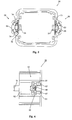
- Fig. 4 is a front view of the female housing of the connector of Fig. 1.
- Fig. 5 is a front view of a casing of the connector of Fig. 1.
- Fig. 6 is a side view of the casing of Fig. 5.
- Fig. 7 is an exploded perspective view of a spring holder of the connector of Fig. 1.
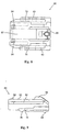
- Fig. 8 is a plan view of the spring holder of Fig. 7.
- Fig. 9 is a side view of the spring holder of Fig. 7.
- Fig. 10 is a partly cut-away plan view of the connector of Fig. 1 showing a state in which the housings have not been fitted in each other.
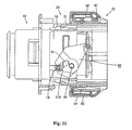
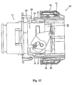
- Figs. 11'to 18 are partly cut-away plan views of the connector of Fig. 1 in successive states during the fitting operation.
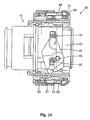
- Fig. 19 is a partly cut-away plan view of the connector of Fig. 1 showing a locked state at completion of fitting.
- Figs. 20A, 20B and 20C are sectional views of the state of parts of the connector of Fig. 1 immediately before the holding arm is unlocked.
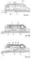
- Figs. 21A, 21B and 21C are sectional views of the state of parts of the connector of Fig. 1 immediately before locking.
- Figs. 22A, 22B and 22C are sectional views of parts of the connector of Fig. 1 in the locked state.
- a connector embodying the present invention is shown in Figs. 1 to 22.
- the connector has a male-side connector housing 10 (hereinafter referred to as male housing 10) and a female-side connector housing portion 20 which, with the casing 30 described below forms a female housing of the connector.
- the portion 20 is called below the female housing 20 and is to be fitted in the male housing 10.
- the side at which each of the male and female housings 10, 20 fit to each other is designated as the front side.
- the male housing 10 is formed by combining two pieces made of synthetic resin material. As shown in Fig. 3, the male housing 10 has a body part 11 having an elongate width direction and generally rectangular. A small hood part 12 projects forward from the body part 11. An installing plate 13 for use when the connector is installed on a panel or the like (not shown) is formed at the base of the hood part 12.
- An array of cavities 14 is formed in rows widthwise in the body part 11.
- Male terminal metal fittings (not shown) are inserted into respective cavities 14 from the rear side and held therein, with tabs thereof projecting into the hood part 12. The male terminal metal fittings are locked by retainers 15 to prevent their removal from the cavities 14.
- the female housing 20 is also made of synthetic resin material.
- the female housing 20 has a body part 21 which can be received in the hood part 12 of the male housing 10 and a large hood part 22 which is located around the periphery of the body part 21 and can be fitted outside the smaller hood part 12.
- the large hood part 22 extends from a position a little rearward from the centre in a front-to-back direction of the female housing 20 to the plane of the front end surface of the body part 21.
- An array of cavities 24 is formed in the female housing 20 in correspondence to the cavities of the male housing 10.
- Female terminal metal fittings (not shown) are inserted into respective cavities 24 from the rear side thereof, and locked by retainers 25 to prevent their removal from the cavities 24.
- a seal ring 26 is fitted on the peripheral surface of the body part 21 of the female housing 20 at the base of the large hood part 22. In use the seal ring 26 is elastically sandwiched between the peripheral surface of the large hood part 22 and the front side of the small hood part 12 of the male housing 10.
- the casing 30 also made of synthetic resin material is rectangularly cylindrical and is longitudinally slidable on the periphery of the female housing 20.
- a pair of cantilevered locking arms 31 project forward from the middle of the right and left inner side surfaces of the casing 30.
- projections 31A are formed on the opposed surfaces of the locking arms 31 at their front ends.
- Each locking arm 31 is elastically deformable in the right-to-left direction so that the locking arms 31 may approach each other.
- pair of guide rails 27 extends in the front-to-back direction. These rails slidably guide the respective locking arm 31, which becomes located between the guide rails 27.
- an insertion groove 28 open forward is formed in the hood part 22 at the central portion between the guide rails 27.
- the groove 28 extends to a position at about the middle of the entire length of the guide rails 27 in the front-to-back direction.
- a pair of locking portions 29 to be locked to the front end surface of the projection 31A of the locking arm 31 are formed on each side of the insertion groove 28. The pair of locking portions 29 can be locked to the projection 31A.
- Release projections 16 capable of penetrating into the insertion grooves 28 are formed at about the middle of the right and left outer side surfaces of the small hood part 12 of the male housing 10.
- a corner of each release projection 16 at its front end is formed as a tapered guide surface 16A.
- a pair of levers 40 for assisting the fitting of the male housing 10 and the female housing 20 is symmetrically mounted on the upper and lower surfaces of the female housing 20.
- the two levers 40 are joined by a cross-bar (not shown) so that they move together in tandem.
- each lever 40 is wide at a first end and tapered towards its other end.
- a curved driving cam slot or groove 41 is formed in the first end of the lever 40, with an entrance opening 41A at an edge of the lever.
- a pin 42 around which a flange partly extends stands up from the other side of the lever 40.
- a bearing hole 43 is formed in the lever 40 near the inward end of the driving cam groove 41.
- a shaft 44 stands up on the upper surface of the large hood part 22 of the female housing 20 near the right (lower side in Fig. 1) end of the upper surface of the large hood part 22.
- the lever 40 is rotatably supported by fitting of the shaft 44 in the bearing hole 43.
- the other lever 40 is correspondingly fitted.
- a cam groove 45 is formed on the upper surface of the casing 30, at one side (upper side in Fig. 1) from the widthwise centre of the upper surface of the casing 30.
- the operation pin 42 of the lever 40 can be fitted in the cam groove 45 slidably and without play.
- a first part 46 providing an entrance of cam groove 45 extends in the insertion direction (arrow in Fig. 2) and its base part bends to extend slightly rearwardly and almost perpendicular to the first part.
- the operation pin 42 is introduced into the cam groove 45 through the entrance 46, with the lever 40 supported by the female housing 20.
- the female housing 20 is pressed into the position at which the locking arms 31 prevents the removal of the female housing 20 in the rearward direction.
- the operation pin 42 is located at a start end 45A of the base part of cam groove 45, and the lever 40 is held so that the entrance 41A of its driving cam groove 41 faces forward.
- a pair of follower pins 18 which can be fitted slidably without play in the two driving cam grooves 41 stand upwardly on the upper and lower surfaces respectively of the small hood part 12 of the male housing 10 at the same positions relative to the centre of the housing 10.
- the male and female housings 10, 20 have locking means for locking them to each other in a normal fit-in state and a spring means for detecting whether the housings 10, 20 have been normally fitted in each other.
- the locking means and the spring means are described below.
- An accommodation part 50 is provided at the middle region of the right and left side surfaces of the casing 30.
- the accommodation part 50 has a pair of spaced side walls 51 (see Fig. 6). Outwardly, the accommodation part 50 is covered'by an arch portion 52.
- each accommodation part 50 accommodates an elongate locking arm 54, connected at the inner surface of its centre portion in its longitudinal direction with the bottom surface of the accommodation part 50.
- the locking arm 54 is elastically deformable in a see-saw member on the connected point.
- About the half of the front portion of the locking arm 54 is located inside the arch portion 52.
- a hook-shaped locking claw 55 is formed at the front end of the locking arm 54.
- the front end surface of the locking claw 55 is formed as a tapered surface 55A.
- a pair of right and left locking hooks 57 project forwardly from the installing plate 13 of the male housing 10 opposite the respective locking arms 54 of the casing 30.
- the locking hooks 57 are elastically deformable.
- Window holes 58 into which the locking arms 31 of the casing 30 can penetrate are formed in the plate 13 inwardly of the roots of the locking hooks 57.
- Receiving portions 59 are formed on the rear surface of plate next to the holes 58.
- the locking arm 31 penetrates into the window hole 58 along the inner side of the locking hook 57, thus preventing the inward elastic deformation of the locking hook 57.
- the locking hook 57 strikes the tapered surface 55A, the locking arm 54 is pivoted.
- the locking claw 55 becomes locked to the rear surface of the locking hook 57, with the locking arm 54 pivoting elastically back into its original state. In this manner, the removal of the casing 30 from the housing 10 is prevented.
- Each accommodation part 50 also accommodates a spring holder 60 covering the locking arm 54 (see Figs. 7 to 9).
- the spring holder 60 incorporates coil springs 61 described later.
- the holder 60 is a separate part, inserted in the accommodation part 50.
- Guide rails 63 provided at right and left ends of a base portion or substrate 62 of the holder 60 are inserted into grooves 51A of side walls 51 of the accommodation part 50 such that the guide rails 63 are slidable longitudinally (see Fig. 22).
- the spring holder 60 is prevented from moving forward when it strikes a front plate 52A of the arch portion 52.
- the spring holder 60 is prevented from moving rearward when a pair of projections 64 and another pair of projections 65 formed on the upper and lower surfaces thereof respectively, are locked to locking portions 66 and 67 (see Figs. 22 and 6) of longitudinally extending insertion grooves formed on the lower surface of the arch portion 52 and on the bottom surface of the accommodation part 50, respectively.
- the holder 60 has an operation portion 68 (lever or tab) elastically deformable due to the formation of slits at both sides thereof formed at the widthwise centre of the rear side of the holder 60.
- the operation portion 68 is located at a position immediately over the locking arm 54.
- a relief groove 70 is formed at the widthwise centre of the lower surface of the substrate 62.
- the relief groove 70 extends rearward from a position located a little rearward from the front end of the substrate 62.
- the front end of the relief groove 70 corresponds to the front end of the locking arm 54, thus allowing the front end of the locking arm 54 to pivot outward elastically, as shown in Fig. 20B.
- the front surface of the relief groove 70 is formed as a restriction surface 71 which strikes the front end of the elastically pivoted locking arm 54, thus preventing a rearward movement of the spring holder 60.
- a pair of spring accommodation chambers 73 is longitudinally formed on the lower surface of the substrate 62 of the spring holder 60 on opposite sides of the locking arm 54.
- Each chamber 73 accommodates the coil spring 61 in a natural state in such a manner that the coil spring 61 is prevented from moving forward.
- a spring seat 74 is fitted on the front end of the coil spring 61. About half of the inner side of the front surface of the chamber 73 is open. Thus, the spring seat 74 faces the opening of the front surface of the chamber 73 when the coil spring 61 is in the chamber 73.
- a holding arm 75 having a hook 76 at its front end is formed integrally on the holder 60 laterally outwardly from each spring accommodation chamber 73.
- the holding arm 75 extends forward and is cantilevered and elastically deformable. As shown in Fig. 20A, a forward movement of the spring holder 60 is prevented when the hook 76 of the holding arm 75 is caught by a catching portion 77 formed on the bottom surface of the accommodation part 50.
- a pair of L-shaped ribs 79 projects in opposite directions from both sides of each locking hook 57 of the male housing 10.
- the ribs 79 are capable of penetrating into the arch portion 52 from the front thereof, with the ribs 79 sandwiching the locking arm 54 therebetween when the casing 30 is fitted on the male housing 10.
- a horizontal leg 79A of the rib 79 shown in Fig. 3 is capable of pressing the coil spring 61 through the spring seat 74.
- the front end of a vertical leg 79B of the rib 79 contacts the holding arm 75, thus so deforming the hook 76 elastically that the hook 76 is unlocked from the catching portion 77.
- the holding arm 75 is unlocked from the catching portion 77 immediately before the locking arm 54 returns to its original position (see Fig. 19) as a result of complete fitting of the casing 30 in the male housing 10.
- the female terminal metal fittings are accommodated in the female housing 20 and locked by the retainers 25.
- the locking portion 29 is locked to the locking arm 31, with the operation pin 42 of the lever 40 fitted on the start portion of the operation cam groove 45, and the casing 30 is mounted on the periphery of the female housing 20 in such a manner that the longitudinal movement thereof is prevented.
- the entrance 41A of the driving cam groove 41 of the lever 41 faces forward.
- the male terminal metal fittings are located in the male housing 10 and locked by the retainers 15.
- each follower pin 18 of the male housing 10 enters the entrance 41A of the driving cam groove 41 of the corresponding lever 40.
- the locking arm 31 rides on the release projection 16 and deforms outward elastically. As a result, the locking portion 29 is unlocked from the locking arm 31. Therefore, the female housing 20 is capable of moving rearward inside the casing 30.
- the holding arm 75 is caught by the catching portion 77, and as described above, the front end of the locking arm 54 is fitted in the relief groove 70 of the spring holder 60 and thus locked to the restriction surface 71. Therefore, the spring holder 60 is prevented from moving rearward.
- the vertical portion 79B of the rib 79 proceeds to a position immediately before the holding arm 75 and strikes the tapered surface 76A of the hook 76, as shown in Fig. 20A. Then, as shown in Fig. 21A, the holding arm 75 continues to deform elastically and is released from the catching portion 77. At this time, as shown in Fig. 21B, the restriction surface 71 contacts the locking claw 55 which is still deformed elastically. Therefore, the spring holder 60 is prevented from moving rearward, although the elastic restoring force of the coil spring 61 is applied to the spring holder 60.
- the locking claw 55 of the locking arm 54 rides across the hook 57 and is locked to the rear surface of the hook 57 by returning to its original state.
- the housings 10, 20 are fitted in each other normally, and the casing 30 and the male housing 10 are locked to each other.
- the locking claw 55 is unlocked from the restriction surface 71 by the above locking operation.
- the restoring elastic force of the coil spring 61 causes the spring holder 60 to move to the retreat position and the coil spring 61 returns to its natural state. See Fig. 22.
- the operation portion 68 is pressed forward in the state shown in Fig. 22 to move the spring holder 60 to the forward position, and is pressed downward to deform elastically.
- the rear side of the locking arm 54 is pressed and the locking claw 55 so deforms that it moves into the relief groove 70 of the spring holder 60.
- the hook 57 is unlocked from the locking claw 55, and the rib 79 of the male housing 10 is pressed downward by the force of the coil springs 61 stored by the pressing of the spring holder 60. Consequently, the separation of the casing 30 from the male housing 10, namely separation of the male housing 10 from the female housing, is accomplished.
- the urging force of the coil spring 61 causes the male housing 10, the casing 30, and the female housing 20 to separate from each other. This allows an operator to securely detect whether the housings 10, 20 have been fitted in each other normally.
- the construction of the lever-type connector is that the casing 30 serving as the operation portion of the lever 40 is provided for the female housing 20 and the return coil spring 61 is provided between the casing 30 and the male housing 10.
- a small spring force is amplified by the lever 40 to such a high extent as to separate both housings 10 and 20 from each other. That is, it is possible to select a small spring force.
- the locking mechanism and the spring mechanism may be provided on only one surface.
- the connector is widthwise long and narrow, it is preferable to provide the connector housings with the locking mechanism and the spring mechanism at both sides in the longitudinal direction thereof.
- the locking mechanism and the spring mechanism are provided at both sides of the connector housings in the longitudinal direction thereof, it is possible to lock the connector housings to each other when both longitudinal ends thereof are normally fitted in each other.
- both connector housings can be held in the normal fit-in state in the whole region of the longitudinal direction thereof.
- the coil spring has been described as an example of the return spring. But other kind of spring such as a leaf spring may be used.
- the spring holder and the locking arm may be set on the male housing.
- the present invention is applicable to a type of a connector having the lever provided exposed to the outside as well as to the type of connector incorporating the lever interiorly.
Landscapes
- Details Of Connecting Devices For Male And Female Coupling (AREA)
Abstract
A lever-type electrical connector has first and
second connector housings (10; 20,30) adapted to be
detachably fitted together in a connected position by
relative movement in a fitting direction. A lever (40)
is rotatably mounted for drawing the connector housings
towards said connected position. Locking means (57) are
provided on the connector housings for locking them
together in the connected position. Springs act
operatively between the connector housings to be
compressed when the connector housings are being moved
towards the connected position, thereby to create a force
urging the connector housings in their separation
direction at least during the movement of the connector
housings towards the connected position. This reduces
the risk of incomplete fitting together of the housings.
Description
- The present invention relates to a lever-type electrical connector, for example a connector suitable for use in a motor vehicle to connect wire bundles.
- It is necessary to connect multipolar electrical connector components to each other with a high fitting force. For this purpose a lever-type connector is employed. In a lever-type connector, for example, a lever having a cam groove is rotatably mounted on a male housing, and a follower fitting in the cam groove is provided on a mating female housing. When the two housings are fitted to each other, with the lever at an initial position, the follower enters the entrance of the cam groove. With rotation of the lever, the housings are drawn together, as the follower moving in the cam groove. The construction is intended to permit fitting of the housings to each other with a small applied force, utilizing the action of the lever. This type of lever-type connector is disclosed in JP-A-6-275337. A similar connector is disclosed in US-A-5476390.
- In the above-described lever-type connector, when the lever has rotated to its rotational termination, the two housings are normally fully fitted in each other. As the lever approaches its rotational termination, the fitting resistance becomes large, while the applied force remains low. Thus, there is a danger that the lever-rotating operation is stopped before the housings are fully fitted to each other. As a result, the housings are left in an incompletely fitted state. Further, even if the lever is rotated to its rotational termination, the housings may be left in an incompletely fitted state owing to an error in the manufacture of component parts of the housings. In either case, it may be very difficult for the operator to detect such incomplete fitting.
- It is an object of the present invention to provide a lever-type connector permitting detection of whether the two connector housings have been normally fitted in each other.
- With a view to achieving this object, according to the invention there is provided a lever-type electrical connector having first and second connector housings adapted to be detachably fitted together in a connected position by relative movement in a fitting direction, and a lever rotatably mounted on the connector for drawing the connector housings in said fitting direction towards said connected position. Locking means are provided on the connector housings for locking them together in the connected position. Spring means are provided to act operatively between the connector housings so as to be resiliently deformed when the connector housings are being moved towards the connected position, thereby to create a force urging the connector housings in their separation direction at least during the movement of the connector housings towards the connected position.
- In this construction, to fit the two connector housings to each other, the lever is rotated. When the connector housings have achieved a normal connected or fitted state, the locking means holds the fitted state. If the fitting operation is stopped before the connector housings are in the normal fitted state, the urging force of the spring means causes the connector housings to separate from each other. Irrespective of the position of the lever therefore, it is possible to securely detect whether or not the connector housings have been fitted in each other normally.
- Preferably the spring means comprises at least one spring having a front end and a rear end, the first connector housing acting upon the front end of the spring to compress it during fitting of the connector housings together, and the second connector housing has a spring holder restraining the rear end of the spring. In this embodiment, the spring holder is arranged to cooperate with the locking means so that, during fitting of the connector housings together, (i) before the locking means locks the connector housings in the connected position the spring holder restrains the spring from relaxation of its compressed state, and (ii) when the locking means has locked the connector housings in the connected position the locking means releases the restraint of the spring to allow at least partial relaxation of the spring. In this embodiment, when the connector housings are fitted to each other, the spring incorporated in the second connector housing is acted on by the first connector housing. At this time, the spring holder restrains the rear end of the spring. Thus, with the progress of the fitting operation, the spring is gradually compressed. Accordingly, if the fitting operation is stopped before the connector housings are fitted on each other normally, they are separated from each other by the spring force. The spring force is relaxed on normal fitting, and this may be detectable by the user.
- Preferably the locking means comprises cooperating members in the form of at least one locking projection provided on the first connector housing and correspondingly at least one resiliently deformable locking arm provided on the second connector housing. The locking projection and locking arm are arranged and shaped so that, when the connector housings are moved towards the connected position, the locking arm engages and is deflected by the locking projection and thereafter locks behind the locking projection in a latch manner. The locking arm when so deflected prevents the spring holder releasing the compressed state of the spring. With the progress of the fit-in operation, the locking arm rides on the locking projection. When the housings have been fitted in each other, the locking arm returns to its original state by its elastic or resilient deformation and is locked to the locking projection. As a result, the connector housings are prevented from separating from each other. In association with this restoring operation of the locking arm, the spring holder releases the rear end of the spring. Thus, the spring is released from the compressed state. Accordingly, after the connector housings are fitted in each other normally, the spring force does not act as a connector separating force.
- When the connector housings are long and narrow, there is a fear that they may be locked to each other with the longitudinal ends dislocated forward or rearward and inclining upward or downward. As a result, the connector housings may not be fitted normally on each other. Preferably, in this case, the locking means act to lock the connector housings together at both ends of the connector housings in their elongation direction and the spring means comprises springs likewise act on the housings at both their ends.
- Preferably, one of the connector housings comprises a housing portion to receive electrical terminals and a casing which receives the housing portion, the housing portion being slidable in the casing in the direction of fitting of the connector housings to each other. The lever is rotatably mounted on the housing portion and has a cam surface, while the other connector housing has a cam follower which engages this cam surface during fitting of the connector housings together. The casing is engageable with the lever so that by its rotation the lever holds the casing and the housing portion together. The locking means and spring means are provided on, and act between, the casing and the other connector housing. With the connector housing portion accommodated in the casing located at the front side, this connector portion is fitted in the other connector housing. Then, the casing is pressed. As a result, the lever rotates. The connector housings are fitted to each other with a small force owing to the action of the lever. When they are normally fitted in each other, the casing is locked to the other connector housing, and the connector housings are held in a normal fitting state. If they are left in an incomplete state, the casing is pressed backward by the urging force of the spring means. This state is detected. In particular, the spring means is provided between the other housing and the casing. Thus, a small spring force is amplified by the lever to to separate the housings from each other. That is, it is possible to set the spring force to a low level.
- Embodiments of the invention will now be described by way of non-limitative example, with reference to the accompanying drawings, in which:-
- Fig. 1 is an exploded plan view of a connector which is an embodiment of the present invention.
- Fig. 2 is an exploded sectional view of the connector of Fig. 1.
- Fig. 3 is a front view of the a male housing of the connector of Fig. 1.
- Fig. 4 is a front view of the female housing of the connector of Fig. 1.
- Fig. 5 is a front view of a casing of the connector of Fig. 1.
- Fig. 6 is a side view of the casing of Fig. 5.
- Fig. 7 is an exploded perspective view of a spring holder of the connector of Fig. 1.
- Fig. 8 is a plan view of the spring holder of Fig. 7.
- Fig. 9 is a side view of the spring holder of Fig. 7.
- Fig. 10 is a partly cut-away plan view of the connector of Fig. 1 showing a state in which the housings have not been fitted in each other.
- Figs.
11'to 18 are partly cut-away plan views of the connector of Fig. 1 in successive states during the fitting operation. - Fig. 19 is a partly cut-away plan view of the connector of Fig. 1 showing a locked state at completion of fitting.
- Figs. 20A, 20B and 20C are sectional views of the state of parts of the connector of Fig. 1 immediately before the holding arm is unlocked.
- Figs. 21A, 21B and 21C are sectional views of the state of parts of the connector of Fig. 1 immediately before locking.
- Figs. 22A, 22B and 22C are sectional views of parts of the connector of Fig. 1 in the locked state.
- A connector embodying the present invention is shown in Figs. 1 to 22. As shown in Figs. 1 and 2, the connector has a male-side connector housing 10 (hereinafter referred to as male housing 10) and a female-side
connector housing portion 20 which, with thecasing 30 described below forms a female housing of the connector. For convenience theportion 20 is called below thefemale housing 20 and is to be fitted in themale housing 10. In the description below, the side at which each of the male andfemale housings - The
male housing 10 is formed by combining two pieces made of synthetic resin material. As shown in Fig. 3, themale housing 10 has abody part 11 having an elongate width direction and generally rectangular. Asmall hood part 12 projects forward from thebody part 11. An installingplate 13 for use when the connector is installed on a panel or the like (not shown) is formed at the base of thehood part 12. - An array of
cavities 14 is formed in rows widthwise in thebody part 11. Male terminal metal fittings (not shown) are inserted intorespective cavities 14 from the rear side and held therein, with tabs thereof projecting into thehood part 12. The male terminal metal fittings are locked byretainers 15 to prevent their removal from thecavities 14. - The
female housing 20 is also made of synthetic resin material. Thefemale housing 20 has abody part 21 which can be received in thehood part 12 of themale housing 10 and alarge hood part 22 which is located around the periphery of thebody part 21 and can be fitted outside thesmaller hood part 12. Thelarge hood part 22 extends from a position a little rearward from the centre in a front-to-back direction of thefemale housing 20 to the plane of the front end surface of thebody part 21. - An array of
cavities 24 is formed in thefemale housing 20 in correspondence to the cavities of themale housing 10. Female terminal metal fittings (not shown) are inserted intorespective cavities 24 from the rear side thereof, and locked byretainers 25 to prevent their removal from thecavities 24. - A
seal ring 26 is fitted on the peripheral surface of thebody part 21 of thefemale housing 20 at the base of thelarge hood part 22. In use theseal ring 26 is elastically sandwiched between the peripheral surface of thelarge hood part 22 and the front side of thesmall hood part 12 of themale housing 10. - As shown in Fig. 5, the
casing 30 also made of synthetic resin material is rectangularly cylindrical and is longitudinally slidable on the periphery of thefemale housing 20. A pair of cantilevered lockingarms 31 project forward from the middle of the right and left inner side surfaces of thecasing 30. As shown in Fig. 2,projections 31A are formed on the opposed surfaces of the lockingarms 31 at their front ends. Each lockingarm 31 is elastically deformable in the right-to-left direction so that the lockingarms 31 may approach each other. - As shown in Fig. 4, at the middle of each of right and left side surfaces of the
large hood part 22 of thefemale housing 20, pair ofguide rails 27 extends in the front-to-back direction. These rails slidably guide therespective locking arm 31, which becomes located between the guide rails 27. As shown in Fig. 2, aninsertion groove 28 open forward is formed in thehood part 22 at the central portion between the guide rails 27. Thegroove 28 extends to a position at about the middle of the entire length of the guide rails 27 in the front-to-back direction. Near the front ends of the guide rails 27, a pair of lockingportions 29 to be locked to the front end surface of theprojection 31A of the lockingarm 31 are formed on each side of theinsertion groove 28. The pair of lockingportions 29 can be locked to theprojection 31A. - As shown by an arrow in Fig. 2, when the
female housing 20 is inserted into thecasing 30 from the rear thereof, the lockingportions 29 strike theprojections 31A so that the two lockingarms 31 elastically deform outward. When the lockingportions 29 pass theprojections 31A, the lockingarms 31 elastically deform inward, to be restored to their original state. Theprojections 31A thus lock against the rear surfaces of the lockingportions 29, to prevent thefemale housing 20 being removed rearwardly from thecasing 30. -
Release projections 16 capable of penetrating into theinsertion grooves 28 are formed at about the middle of the right and left outer side surfaces of thesmall hood part 12 of themale housing 10. A corner of eachrelease projection 16 at its front end is formed as atapered guide surface 16A. When therelease projection 16 penetrates into theinsertion groove 28 from the front side thereof, theguide surface 16A strikes the front end of theprojection 31A, thus deforming the lockingarm 31 elastically outward. As a result, the lockingportion 29 is unlocked from the lockingarm 31, and thefemale housing 20 is allowed to move rearwardly inside thecasing 30. - A pair of
levers 40 for assisting the fitting of themale housing 10 and thefemale housing 20 is symmetrically mounted on the upper and lower surfaces of thefemale housing 20. The twolevers 40 are joined by a cross-bar (not shown) so that they move together in tandem. As shown in Fig. 1, eachlever 40 is wide at a first end and tapered towards its other end. A curved driving cam slot orgroove 41 is formed in the first end of thelever 40, with anentrance opening 41A at an edge of the lever. Apin 42 around which a flange partly extends stands up from the other side of thelever 40. - A bearing
hole 43 is formed in thelever 40 near the inward end of the drivingcam groove 41. Ashaft 44 stands up on the upper surface of thelarge hood part 22 of thefemale housing 20 near the right (lower side in Fig. 1) end of the upper surface of thelarge hood part 22. Thelever 40 is rotatably supported by fitting of theshaft 44 in thebearing hole 43. Theother lever 40 is correspondingly fitted. - As shown in Figs. 1 and 2, a
cam groove 45 is formed on the upper surface of thecasing 30, at one side (upper side in Fig. 1) from the widthwise centre of the upper surface of thecasing 30. Theoperation pin 42 of thelever 40 can be fitted in thecam groove 45 slidably and without play. As shown in Fig. 2, afirst part 46 providing an entrance ofcam groove 45 extends in the insertion direction (arrow in Fig. 2) and its base part bends to extend slightly rearwardly and almost perpendicular to the first part. - The
operation pin 42 is introduced into thecam groove 45 through theentrance 46, with thelever 40 supported by thefemale housing 20. In this state, thefemale housing 20 is pressed into the position at which the lockingarms 31 prevents the removal of thefemale housing 20 in the rearward direction. As a result, as shown in Fig. 10, theoperation pin 42 is located at astart end 45A of the base part ofcam groove 45, and thelever 40 is held so that theentrance 41A of itsdriving cam groove 41 faces forward. - A pair of follower pins 18 which can be fitted slidably without play in the two driving
cam grooves 41 stand upwardly on the upper and lower surfaces respectively of thesmall hood part 12 of themale housing 10 at the same positions relative to the centre of thehousing 10. - The male and
female housings housings - An
accommodation part 50 is provided at the middle region of the right and left side surfaces of thecasing 30. Theaccommodation part 50 has a pair of spaced side walls 51 (see Fig. 6). Outwardly, theaccommodation part 50 is covered'by anarch portion 52. - As shown at the lower side of Fig. 2, each
accommodation part 50 accommodates anelongate locking arm 54, connected at the inner surface of its centre portion in its longitudinal direction with the bottom surface of theaccommodation part 50. The lockingarm 54 is elastically deformable in a see-saw member on the connected point. About the half of the front portion of the lockingarm 54 is located inside thearch portion 52. A hook-shaped lockingclaw 55 is formed at the front end of the lockingarm 54. The front end surface of the lockingclaw 55 is formed as atapered surface 55A. - A pair of right and left locking hooks 57 project forwardly from the installing
plate 13 of themale housing 10 opposite the respective lockingarms 54 of thecasing 30. The locking hooks 57 are elastically deformable. Window holes 58 into which the lockingarms 31 of thecasing 30 can penetrate are formed in theplate 13 inwardly of the roots of the locking hooks 57. Receivingportions 59 are formed on the rear surface of plate next to theholes 58. When the lockingarm 31 penetrates into thewindow hole 58 and engages the receivingportion 59 at its inner side, the lockinghook 57 is prevented from deforming inward elastically. - Thus, when the
casing 30 is fitted in themale housing 10, initially, the lockingarm 31 penetrates into thewindow hole 58 along the inner side of the lockinghook 57, thus preventing the inward elastic deformation of the lockinghook 57. When the lockinghook 57 strikes the taperedsurface 55A, the lockingarm 54 is pivoted. When thecasing 30 has been inserted into a predetermined position on themale housing 10, the lockingclaw 55 becomes locked to the rear surface of the lockinghook 57, with the lockingarm 54 pivoting elastically back into its original state. In this manner, the removal of thecasing 30 from thehousing 10 is prevented. - Each
accommodation part 50 also accommodates aspring holder 60 covering the locking arm 54 (see Figs. 7 to 9). Thespring holder 60 incorporates coil springs 61 described later. Theholder 60 is a separate part, inserted in theaccommodation part 50.Guide rails 63 provided at right and left ends of a base portion orsubstrate 62 of theholder 60 are inserted intogrooves 51A ofside walls 51 of theaccommodation part 50 such that the guide rails 63 are slidable longitudinally (see Fig. 22). Thespring holder 60 is prevented from moving forward when it strikes afront plate 52A of thearch portion 52. Thespring holder 60 is prevented from moving rearward when a pair ofprojections 64 and another pair ofprojections 65 formed on the upper and lower surfaces thereof respectively, are locked to lockingportions 66 and 67 (see Figs. 22 and 6) of longitudinally extending insertion grooves formed on the lower surface of thearch portion 52 and on the bottom surface of theaccommodation part 50, respectively. - As shown in Fig. 8, the
holder 60 has an operation portion 68 (lever or tab) elastically deformable due to the formation of slits at both sides thereof formed at the widthwise centre of the rear side of theholder 60. When thespring holder 60 is located at the rear position shown in Fig. 22, theoperation portion 68 is located at a position immediately over the lockingarm 54. - As shown in Fig. 20, a
relief groove 70 is formed at the widthwise centre of the lower surface of thesubstrate 62. Therelief groove 70 extends rearward from a position located a little rearward from the front end of thesubstrate 62. When thespring holder 60 is located at a front position, the front end of therelief groove 70 corresponds to the front end of the lockingarm 54, thus allowing the front end of the lockingarm 54 to pivot outward elastically, as shown in Fig. 20B. - The front surface of the
relief groove 70 is formed as arestriction surface 71 which strikes the front end of the elastically pivoted lockingarm 54, thus preventing a rearward movement of thespring holder 60. - A pair of
spring accommodation chambers 73 is longitudinally formed on the lower surface of thesubstrate 62 of thespring holder 60 on opposite sides of the lockingarm 54. Eachchamber 73 accommodates thecoil spring 61 in a natural state in such a manner that thecoil spring 61 is prevented from moving forward. Aspring seat 74 is fitted on the front end of thecoil spring 61. About half of the inner side of the front surface of thechamber 73 is open. Thus, thespring seat 74 faces the opening of the front surface of thechamber 73 when thecoil spring 61 is in thechamber 73. - A holding
arm 75 having ahook 76 at its front end is formed integrally on theholder 60 laterally outwardly from eachspring accommodation chamber 73. The holdingarm 75 extends forward and is cantilevered and elastically deformable. As shown in Fig. 20A, a forward movement of thespring holder 60 is prevented when thehook 76 of the holdingarm 75 is caught by a catchingportion 77 formed on the bottom surface of theaccommodation part 50. - As shown in Figs. 1 to 3, a pair of L-shaped
ribs 79 projects in opposite directions from both sides of each lockinghook 57 of themale housing 10. Theribs 79 are capable of penetrating into thearch portion 52 from the front thereof, with theribs 79 sandwiching the lockingarm 54 therebetween when thecasing 30 is fitted on themale housing 10. Ahorizontal leg 79A of therib 79 shown in Fig. 3 is capable of pressing thecoil spring 61 through thespring seat 74. The front end of avertical leg 79B of therib 79 contacts the holdingarm 75, thus so deforming thehook 76 elastically that thehook 76 is unlocked from the catchingportion 77. - The holding
arm 75 is unlocked from the catchingportion 77 immediately before the lockingarm 54 returns to its original position (see Fig. 19) as a result of complete fitting of thecasing 30 in themale housing 10. - The operation of the lever-type connector of this embodiment is'described below.
- The female terminal metal fittings are accommodated in the
female housing 20 and locked by theretainers 25. When thefemale housing 20 is inserted into thecasing 30 from the rear thereof, as shown by an arrow in Fig. 10, the lockingportion 29 is locked to the lockingarm 31, with theoperation pin 42 of thelever 40 fitted on the start portion of theoperation cam groove 45, and thecasing 30 is mounted on the periphery of thefemale housing 20 in such a manner that the longitudinal movement thereof is prevented. At this time, theentrance 41A of the drivingcam groove 41 of thelever 41 faces forward. - The male terminal metal fittings are located in the
male housing 10 and locked by theretainers 15. - In this state, the
casing 30 mounted on thefemale housing 20 is fitted on the outer side of thesmall hood part 12 of themale housing 10. As shown in Fig. 11, eachfollower pin 18 of themale housing 10 enters theentrance 41A of the drivingcam groove 41 of the correspondinglever 40. Next, as shown in Fig. 12, the lockingarm 31 rides on therelease projection 16 and deforms outward elastically. As a result, the lockingportion 29 is unlocked from the lockingarm 31. Therefore, thefemale housing 20 is capable of moving rearward inside thecasing 30. - When the
casing 30 is further pressed towards themale housing 10, as shown in Fig. 13, thecam groove 45 presses theoperation pin 42 forward. Thus, thelever 40 is rotated counterclockwise on theshaft 44. As thefollower pin 18 moves to the rear side of the drivingcam groove 41, the twohousings arm 31 that has deformed outward elastically interferes with the lockinghook 57 of themale housing 10, thus deforming the lockinghook 57 outward elastically. - With further progress of the fitting operation, as shown in Fig. 14, with the locking
arm 31 and the lockinghook 57 returning to the original state, the lockingarm 31 penetrates into thewindow hole 58 along the inner side of the lockinghook 57. As a result, the inward elastic deformation of the lockingarm 31 is prevented, and the inward elastic deformation of the lockinghook 57 is also prevented. In this state, as shown in the lower side of Fig. 15, the lockinghook 57 strikes the taperedsurface 55A of the lockingclaw 55 of the lockingarm 54. Then, as shown in Fig. 16, the lockinghook 57 presses thetapered surface 55A. As a result, the lockingclaw 55 deforms outward elastically, penetrating into therelief groove 70 of thespring holder 60. - At this time, as shown in the upper side of Fig. 16, the
rib 79 of themale housing 10 penetrates into thearch portion 52, and eachhorizontal portion 79A contacts thecorresponding spring seat 74. - As shown in Fig. 20A, the holding
arm 75 is caught by the catchingportion 77, and as described above, the front end of the lockingarm 54 is fitted in therelief groove 70 of thespring holder 60 and thus locked to therestriction surface 71. Therefore, thespring holder 60 is prevented from moving rearward. - Therefore, with further penetration of the
rib 79 into thearch portion 52, as shown in the upper side of Fig. 17, thecoil spring 61 is gradually compressed by thespring seat 74. Meanwhile, the twohousings - In this state, the terminal metal fittings of both
housings housings casing 30 is so urged that it moves away from themale housing 10 by the restoring elastic force of the coil springs 61. Further, the twohousings lever 40 in the opposite direction. Thereby, it is possible to detect that thehousings - Immediately before the locking
claw 55 rides over the lockinghook 57 as a result of continuation of the fit-in operation as shown in Fig. 18, thevertical portion 79B of therib 79 proceeds to a position immediately before the holdingarm 75 and strikes the taperedsurface 76A of thehook 76, as shown in Fig. 20A. Then, as shown in Fig. 21A, the holdingarm 75 continues to deform elastically and is released from the catchingportion 77. At this time, as shown in Fig. 21B, therestriction surface 71 contacts the lockingclaw 55 which is still deformed elastically. Therefore, thespring holder 60 is prevented from moving rearward, although the elastic restoring force of thecoil spring 61 is applied to thespring holder 60. - With further progress of the fitting operation, the locking
claw 55 of the lockingarm 54 rides across thehook 57 and is locked to the rear surface of thehook 57 by returning to its original state. Now, thehousings casing 30 and themale housing 10 are locked to each other. - Further, the locking
claw 55 is unlocked from therestriction surface 71 by the above locking operation. Thus, the restoring elastic force of thecoil spring 61 causes thespring holder 60 to move to the retreat position and thecoil spring 61 returns to its natural state. See Fig. 22. - To unlock the
housings operation portion 68 is pressed forward in the state shown in Fig. 22 to move thespring holder 60 to the forward position, and is pressed downward to deform elastically. As a result, the rear side of the lockingarm 54 is pressed and the lockingclaw 55 so deforms that it moves into therelief groove 70 of thespring holder 60. Thereby, thehook 57 is unlocked from the lockingclaw 55, and therib 79 of themale housing 10 is pressed downward by the force of the coil springs 61 stored by the pressing of thespring holder 60. Consequently, the separation of thecasing 30 from themale housing 10, namely separation of themale housing 10 from the female housing, is accomplished. - As is apparent from the foregoing description, in this embodiment, when the fitting operation is stopped before the
housings coil spring 61 causes themale housing 10, thecasing 30, and thefemale housing 20 to separate from each other. This allows an operator to securely detect whether thehousings - When the
housings spring holder 60 is released, and the compression state of the coil springs 61 is released, so that thespring holder 60 is moved rearward. That is, when thehousings housings - The construction of the lever-type connector is that the
casing 30 serving as the operation portion of thelever 40 is provided for thefemale housing 20 and thereturn coil spring 61 is provided between thecasing 30 and themale housing 10. A small spring force is amplified by thelever 40 to such a high extent as to separate bothhousings - The present invention is not limited to the embodiment explained above. For example, the following embodiments are included in the technical scope of the present invention. Further, various modifications can be made without departing from the spirit and scope of the present invention.
- (1) The locking mechanism and the spring mechanism may be provided on only one surface.
- On the other hand, if the connector is widthwise long and narrow, it is preferable to provide the connector housings with the locking mechanism and the spring mechanism at both sides in the longitudinal direction thereof.
- That is, when the connector housings are long and narrow, there is a fear that they are locked to each other, with the longitudinal ends dislocated forward or rearward and inclining upward or downward. As a result, the front ends or the rear ends of the connector housings that has been dislocated rearward may not be fitted normally on each other.
- According to the lever-type connector of the present invention, because the locking mechanism and the spring mechanism are provided at both sides of the connector housings in the longitudinal direction thereof, it is possible to lock the connector housings to each other when both longitudinal ends thereof are normally fitted in each other. Thus, both connector housings can be held in the normal fit-in state in the whole region of the longitudinal direction thereof.
- (2) In the above-described embodiment, the coil spring has been described as an example of the return spring. But other kind of spring such as a leaf spring may be used.
- (3) The spring holder and the locking arm may be set on the male housing.
- (4) The present invention is applicable to a type of a connector having the lever provided exposed to the outside as well as to the type of connector incorporating the lever interiorly.
- While the invention has been described in conjunction with the exemplary embodiments described above, many equivalent modifications and variations will be apparent to those skilled in the art when given this disclosure. Accordingly, the exemplary embodiments of the invention set forth above are considered to be illustrative and not limiting. Various changes to the described embodiments may be made without departing from the spirit and scope of the invention.
Claims (6)
- A lever-type electrical connector havingcharacterised by:first and second connector housings (10; 20,30) adapted to be detachably fitted together in a connected position by relative movement in a fitting direction,a lever (40) rotatably mounted on said connector for drawing said connector housings in said fitting direction towards said connected position,locking means (54,57) provided on said connector housings for locking them together in said connected position, andspring means (61) provided to act operatively between said connector housings so as to be resiliently deformed when said connector housings are being moved towards said connected position, thereby to create a force urging said connector housings in their separation direction at least during the movement of said connector housings towards said connected position.
- A connector according to claim 1, wherein said spring means comprises at least one spring (61) having a front end and a rear end, said first connector housing (10) acting upon said front end of said spring (61) to compress it during fitting of said connector housings (10,20) together, and
said second connector housing (20,30) has a spring holder (60) restraining said rear end of said spring, said spring holder (60) being arranged to cooperate with said locking means (54,57) so that, during fitting of the connector housings together, (i) before said locking means (54,57) locks said connector housings in said connected position said spring holder (60) restrains said spring (61) from relaxation, and (ii) when said locking means (54,57) has locked said connector housings in said connected position said locking means (54,57) releases the restraint of said spring to allow at least partial relaxation. - A connector according to claim 2, wherein said locking means comprises cooperating members in the form of at least one locking projection (57) provided on said first connector housing (10) and correspondingly at least one resiliently deformable locking arm (54) provided on said second connector housing (20,30), said locking projection (54) and locking arm (57) being arranged and shaped so that, when said connector housings are moved towards said connected position, said locking arm engages and is deflected by said locking projection and thereafter locks behind said locking projection in a latch manner, said locking arm when so deflected preventing said spring holder (60) from releasing the compressed state of the spring (61).
- A lever-type connector according to claim 2 or 3, wherein the spring holder (60) is displaceable on the second connector housing (20,30) in the fitting direction, to compress and relax said spring (61).
- A lever-type connector according to any one of claims 1 to 3, wherein both said connector housings (10; 20,30) are elongate with their elongation direction extending transversely to the direction in which they are relatively moved towards said connected position, each said connector housing having a plurality of cavities (14,24) for receiving electrical terminals arranged in at least one row extending in said elongation direction, said locking means (54,57) acting to lock said connector housings together at both ends of said connector housings in said elongation direction and said spring means comprising springs (61) acting on said housings at both ends of said connector housings in said elongation direction.
- A lever-type connector according to any one of claims 1 to 5, wherein one of said connector housings comprises a housing portion (20) to receive electrical terminals and a casing (30) which receives said housing portion, said housing portion (20) being slidable in said casing in the direction of fitting of said connector housings to each other,said lever (40) being rotatably mounted on said housing portion (20) and having a cam surface (41),the other (10) of said connector housings having a cam follower (18) which engages said cam surface (41) during fitting of the connector housings together,said casing (30) being engageable with said lever (40) so that by its rotation said lever (40) holds said casing (30) and said housing portion (20) together,said locking means (54,57) and said spring means (61) being provided on, and acting between, said casing (30) and said other connector housing (10).
Applications Claiming Priority (2)
| Application Number | Priority Date | Filing Date | Title |
|---|---|---|---|
| JP21877799A JP3538750B2 (en) | 1999-08-02 | 1999-08-02 | Lever type connector |
| JP21877799 | 1999-08-02 |
Publications (1)
| Publication Number | Publication Date |
|---|---|
| EP1075052A1 true EP1075052A1 (en) | 2001-02-07 |
Family
ID=16725228
Family Applications (1)
| Application Number | Title | Priority Date | Filing Date |
|---|---|---|---|
| EP00306488A Withdrawn EP1075052A1 (en) | 1999-08-02 | 2000-07-31 | Lever-type electrical connector |
Country Status (3)
| Country | Link |
|---|---|
| US (1) | US6315585B1 (en) |
| EP (1) | EP1075052A1 (en) |
| JP (1) | JP3538750B2 (en) |
Cited By (2)
| Publication number | Priority date | Publication date | Assignee | Title |
|---|---|---|---|---|
| EP1333543A3 (en) * | 2002-01-31 | 2004-12-08 | J.S.T. Mfg. Co., Ltd. | Electric connector with a locking mechanism |
| WO2021105135A1 (en) * | 2019-11-25 | 2021-06-03 | Hirschmann Automotive Gmbh | Plug-in connection which can be pre-loaded with a high force in a backlash-free manner |
Families Citing this family (31)
| Publication number | Priority date | Publication date | Assignee | Title |
|---|---|---|---|---|
| US6676452B2 (en) * | 2001-04-09 | 2004-01-13 | Methode Electronics, Inc. | Unlock proof squib connector |
| JP3920055B2 (en) * | 2001-04-12 | 2007-05-30 | 矢崎総業株式会社 | Method of assembling half-fitting prevention connector and half-fitting prevention connector |
| US6660950B2 (en) * | 2001-07-24 | 2003-12-09 | Danilo E. Fonseca | Data line switch |
| US6517372B1 (en) * | 2001-12-26 | 2003-02-11 | Hon Hai Precision Ind. Co., Ltd. | Quick release shock/vibration connector assembly |
| JP2003249309A (en) * | 2002-02-26 | 2003-09-05 | Sumitomo Wiring Syst Ltd | Split connector |
| JP3806926B2 (en) * | 2002-03-01 | 2006-08-09 | 住友電装株式会社 | connector |
| JP2003308927A (en) * | 2002-04-12 | 2003-10-31 | Sumitomo Wiring Syst Ltd | Connector |
| ITTO20020701A1 (en) * | 2002-08-06 | 2004-02-07 | Framatome Connectors Int | ELECTRIC CONNECTOR. |
| JP2004214106A (en) * | 2003-01-07 | 2004-07-29 | Sumitomo Wiring Syst Ltd | Lever type connector |
| US6733336B1 (en) | 2003-04-03 | 2004-05-11 | John Mezzalingua Associates, Inc. | Compression-type hard-line connector |
| US7465015B2 (en) * | 2004-12-06 | 2008-12-16 | Silverbrook Research Pty Ltd | Capping system for inkjet printhead assembly |
| JP2006313730A (en) * | 2005-04-08 | 2006-11-16 | Sumitomo Wiring Syst Ltd | Connector device |
| JP4577200B2 (en) * | 2005-12-08 | 2010-11-10 | 住友電装株式会社 | Connector device |
| GB0609240D0 (en) | 2006-05-10 | 2006-06-21 | Mitchell Ciaran | Seat top console for vehicle entertainment and accessories |
| US7431605B2 (en) * | 2006-12-06 | 2008-10-07 | J.S.T. Corporation | Connector position assurance apparatus |
| DE202006019203U1 (en) * | 2006-12-20 | 2007-02-22 | Rosenberger Hochfrequenztechnik Gmbh & Co. Kg | Coaxial plug e.g. for oscilloscope, has housing provided with axially oriented slots for receiving BNC-pin |
| JP2009259442A (en) * | 2008-04-14 | 2009-11-05 | Molex Inc | Connector |
| JP5472720B2 (en) * | 2009-12-23 | 2014-04-16 | 住友電装株式会社 | Lever type connector |
| JP5387381B2 (en) * | 2009-12-17 | 2014-01-15 | 住友電装株式会社 | Lever type connector |
| JP5407960B2 (en) * | 2010-03-17 | 2014-02-05 | 住友電装株式会社 | Lever type connector |
| JP5370254B2 (en) * | 2010-04-28 | 2013-12-18 | 住友電装株式会社 | connector |
| JP5961493B2 (en) * | 2012-09-04 | 2016-08-02 | 矢崎総業株式会社 | Connector device |
| US9997861B2 (en) | 2015-12-10 | 2018-06-12 | International Business Machines Corporation | Force limiting latch indicator |
| JP6569131B2 (en) * | 2016-04-26 | 2019-09-04 | 株式会社オートネットワーク技術研究所 | Electrical connection device having fitting detection function |
| JP2018022628A (en) * | 2016-08-04 | 2018-02-08 | 日本圧着端子製造株式会社 | Connector member and connector |
| JP2018022630A (en) * | 2016-08-04 | 2018-02-08 | 日本圧着端子製造株式会社 | Connector member and connector |
| JP2018022629A (en) * | 2016-08-04 | 2018-02-08 | 日本圧着端子製造株式会社 | Connector member and connector |
| DE102020125381A1 (en) * | 2020-09-29 | 2022-03-31 | Harting Electric Gmbh & Co. Kg | Fastening system for connectors |
| TWI784586B (en) * | 2021-06-21 | 2022-11-21 | 啟碁科技股份有限公司 | Electronic device and unlocking cover thereof |
| JP2023050998A (en) * | 2021-09-30 | 2023-04-11 | 株式会社オートネットワーク技術研究所 | Connectors and connector assemblies |
| DE102023106568B4 (en) * | 2023-03-16 | 2025-01-30 | Lisa Dräxlmaier GmbH | Plug connection with a power-amplifier connector and a corresponding header |
Citations (4)
| Publication number | Priority date | Publication date | Assignee | Title |
|---|---|---|---|---|
| EP0483853A2 (en) * | 1990-10-31 | 1992-05-06 | Yazaki Corporation | Connector assembly |
| US5201670A (en) * | 1990-11-30 | 1993-04-13 | Yazaki Corporation | Connectors |
| US5230635A (en) * | 1991-06-25 | 1993-07-27 | Yazaki Corporation | Connector with lever |
| US5630727A (en) * | 1994-09-09 | 1997-05-20 | Yasaki Corporation | Lever lock mechanism for lever fitting type connector |
Family Cites Families (2)
| Publication number | Priority date | Publication date | Assignee | Title |
|---|---|---|---|---|
| JP2772309B2 (en) | 1993-03-17 | 1998-07-02 | 矢崎総業株式会社 | Lever connection type connector |
| US6120308A (en) * | 1997-07-01 | 2000-09-19 | Sumitomo Wiring Systems, Ltd. | Electrical connector assembly which can be rotatably connected and disconnected |
-
1999
- 1999-08-02 JP JP21877799A patent/JP3538750B2/en not_active Expired - Fee Related
-
2000
- 2000-07-31 EP EP00306488A patent/EP1075052A1/en not_active Withdrawn
- 2000-08-02 US US09/630,445 patent/US6315585B1/en not_active Expired - Fee Related
Patent Citations (4)
| Publication number | Priority date | Publication date | Assignee | Title |
|---|---|---|---|---|
| EP0483853A2 (en) * | 1990-10-31 | 1992-05-06 | Yazaki Corporation | Connector assembly |
| US5201670A (en) * | 1990-11-30 | 1993-04-13 | Yazaki Corporation | Connectors |
| US5230635A (en) * | 1991-06-25 | 1993-07-27 | Yazaki Corporation | Connector with lever |
| US5630727A (en) * | 1994-09-09 | 1997-05-20 | Yasaki Corporation | Lever lock mechanism for lever fitting type connector |
Cited By (2)
| Publication number | Priority date | Publication date | Assignee | Title |
|---|---|---|---|---|
| EP1333543A3 (en) * | 2002-01-31 | 2004-12-08 | J.S.T. Mfg. Co., Ltd. | Electric connector with a locking mechanism |
| WO2021105135A1 (en) * | 2019-11-25 | 2021-06-03 | Hirschmann Automotive Gmbh | Plug-in connection which can be pre-loaded with a high force in a backlash-free manner |
Also Published As
| Publication number | Publication date |
|---|---|
| JP3538750B2 (en) | 2004-06-14 |
| US6315585B1 (en) | 2001-11-13 |
| JP2001043930A (en) | 2001-02-16 |
Similar Documents
| Publication | Publication Date | Title |
|---|---|---|
| US6315585B1 (en) | Lever-type electrical connector | |
| EP2249440B1 (en) | A connector, connector assembly and connection method | |
| US6135802A (en) | Cover-equipped connector | |
| US7201591B2 (en) | Lever-type connector | |
| EP0841724B1 (en) | A connector | |
| JP7251398B2 (en) | connector | |
| US5618207A (en) | Retaining method and double-retaining connector therefor | |
| US6386898B1 (en) | Connector fitting construction | |
| EP0923164B1 (en) | Electrical connector assembly with terminal retainer system | |
| JPH07335322A (en) | Connector coupling detector | |
| CA2353425C (en) | Connector fitting structure | |
| JPH0581967U (en) | connector | |
| JP3365234B2 (en) | connector | |
| US7011536B2 (en) | Connector and a connector assembly | |
| EP0881722B1 (en) | Connector correction devices and methods for correcting same | |
| KR20210001980A (en) | Electrical connector with mate assist having feedback | |
| EP0954061A1 (en) | A connector | |
| US7287993B2 (en) | Connector having a movable member | |
| US6361334B1 (en) | Cover-provided connector | |
| US6638099B2 (en) | Connector | |
| US7063577B2 (en) | Split-type connector assembly and method of assembling it | |
| JP3133920B2 (en) | Connector connection detection device | |
| JP3767140B2 (en) | connector | |
| JP3591621B2 (en) | connector | |
| EP1001494B1 (en) | Electrical connector with terminal insertion detection means |
Legal Events
| Date | Code | Title | Description |
|---|---|---|---|
| PUAI | Public reference made under article 153(3) epc to a published international application that has entered the european phase |
Free format text: ORIGINAL CODE: 0009012 |
|
| 17P | Request for examination filed |
Effective date: 20000821 |
|
| AK | Designated contracting states |
Kind code of ref document: A1 Designated state(s): DE FR GB IT |
|
| AX | Request for extension of the european patent |
Free format text: AL;LT;LV;MK;RO;SI |
|
| AKX | Designation fees paid |
Free format text: DE FR GB IT |
|
| STAA | Information on the status of an ep patent application or granted ep patent |
Free format text: STATUS: THE APPLICATION HAS BEEN WITHDRAWN |
|
| 18W | Application withdrawn |
Withdrawal date: 20020109 |