EP1001494B1 - Electrical connector with terminal insertion detection means - Google Patents
Electrical connector with terminal insertion detection means Download PDFInfo
- Publication number
- EP1001494B1 EP1001494B1 EP99121330A EP99121330A EP1001494B1 EP 1001494 B1 EP1001494 B1 EP 1001494B1 EP 99121330 A EP99121330 A EP 99121330A EP 99121330 A EP99121330 A EP 99121330A EP 1001494 B1 EP1001494 B1 EP 1001494B1
- Authority
- EP
- European Patent Office
- Prior art keywords
- connector
- retaining
- cavity
- terminal
- wall
- Prior art date
- Legal status (The legal status is an assumption and is not a legal conclusion. Google has not performed a legal analysis and makes no representation as to the accuracy of the status listed.)
- Expired - Lifetime
Links
Images


Classifications
-
- H—ELECTRICITY
- H01—ELECTRIC ELEMENTS
- H01R—ELECTRICALLY-CONDUCTIVE CONNECTIONS; STRUCTURAL ASSOCIATIONS OF A PLURALITY OF MUTUALLY-INSULATED ELECTRICAL CONNECTING ELEMENTS; COUPLING DEVICES; CURRENT COLLECTORS
- H01R13/00—Details of coupling devices of the kinds covered by groups H01R12/70 or H01R24/00 - H01R33/00
- H01R13/40—Securing contact members in or to a base or case; Insulating of contact members
- H01R13/42—Securing in a demountable manner
- H01R13/436—Securing a plurality of contact members by one locking piece or operation
- H01R13/4361—Insertion of locking piece perpendicular to direction of contact insertion
-
- H—ELECTRICITY
- H01—ELECTRIC ELEMENTS
- H01R—ELECTRICALLY-CONDUCTIVE CONNECTIONS; STRUCTURAL ASSOCIATIONS OF A PLURALITY OF MUTUALLY-INSULATED ELECTRICAL CONNECTING ELEMENTS; COUPLING DEVICES; CURRENT COLLECTORS
- H01R13/00—Details of coupling devices of the kinds covered by groups H01R12/70 or H01R24/00 - H01R33/00
- H01R13/40—Securing contact members in or to a base or case; Insulating of contact members
- H01R13/42—Securing in a demountable manner
- H01R13/422—Securing in resilient one-piece base or case, e.g. by friction; One-piece base or case formed with resilient locking means
- H01R13/4223—Securing in resilient one-piece base or case, e.g. by friction; One-piece base or case formed with resilient locking means comprising integral flexible contact retaining fingers
-
- H—ELECTRICITY
- H01—ELECTRIC ELEMENTS
- H01R—ELECTRICALLY-CONDUCTIVE CONNECTIONS; STRUCTURAL ASSOCIATIONS OF A PLURALITY OF MUTUALLY-INSULATED ELECTRICAL CONNECTING ELEMENTS; COUPLING DEVICES; CURRENT COLLECTORS
- H01R13/00—Details of coupling devices of the kinds covered by groups H01R12/70 or H01R24/00 - H01R33/00
- H01R13/62—Means for facilitating engagement or disengagement of coupling parts or for holding them in engagement
- H01R13/639—Additional means for holding or locking coupling parts together, after engagement, e.g. separate keylock, retainer strap
- H01R13/6392—Additional means for holding or locking coupling parts together, after engagement, e.g. separate keylock, retainer strap for extension cord
-
- H—ELECTRICITY
- H01—ELECTRIC ELEMENTS
- H01R—ELECTRICALLY-CONDUCTIVE CONNECTIONS; STRUCTURAL ASSOCIATIONS OF A PLURALITY OF MUTUALLY-INSULATED ELECTRICAL CONNECTING ELEMENTS; COUPLING DEVICES; CURRENT COLLECTORS
- H01R13/00—Details of coupling devices of the kinds covered by groups H01R12/70 or H01R24/00 - H01R33/00
- H01R13/64—Means for preventing incorrect coupling
Definitions
- the present invention relates to an electric connector, in particular for a circuit for activating a vehicle air-bag device, and to an electric connecting unit defined by connection of said connector to a complementary connector in an assembly direction.
- Electric connectors of the above type are known to comprise an insulating casing defining a number of cavities having axes parallel to said assembly direction and for housing respective electric terminals, which are connected to respective electric cables and retained inside the cavities by main retaining means; and, for each cavity, the main retaining means comprise a retaining seat formed in the respective terminal, and an elastically deformable latch member forming part of the casing and which clicks onto the seat.
- Such connectors also comprise auxiliary retaining means for determining correct insertion, and further ensuring retention, of the terminals inside the respective cavities.
- the auxiliary retaining means normally comprise a movable member which clicks onto the casing and/or onto the terminals and may either be hinged to and integral with the casing, or defined by a separate member. Whichever the case, the movable member only clicks onto the casing and/or onto the terminals when all the terminals are inserted correctly and locked inside the respective cavities by the respective latch members. Conversely, if any one of the terminals is not properly or fully inserted, the main retaining means remain deformed, thus preventing assembly of the movable member and so enabling the fault to be detected.
- the present invention also relates to an electric connecting unit as defined in Claim 8.
- number 1 indicates as a whole an electric connecting unit comprising two electric connectors 2, 3 connectable to each other in a longitudinal assembly direction A, and a device 4 for click-on connecting connectors 2, 3 in a final assembly position.
- Connector 2 ( Figures 1 to 6) comprises a substantially parallelepiped-shaped insulating casing 5 defining a number of - in the example shown, three - longitudinal through cavities 6 arranged side by side in a direction B perpendicular to direction A, and for housing respective female electric terminals 7 connected to respective electric cables 8.
- Connector 2 also comprises main retaining means 9 for retaining each terminal 7 in a correct insertion position inside respective cavity 6; and auxiliary retaining means 10 for determining correct insertion of terminals 7 inside cavities 6 and preventing withdrawal of the terminals.
- Casing 5 comprises a plate 11 (for the purpose explained later on) projecting frontwards - substantially as an extension of a top wall 12 of casing 5 parallel to directions A and B - and having, on the outside, on the opposite side to cavities 6, two ribs 13 parallel to direction A.
- Connector 3 ( Figures 1 to 5 and Figure 7) comprises an insulating casing 14 having a substantially parallelepiped-shaped rear portion 15 defining a number of - in the example shown, three - longitudinal cavities 16 for housing respective male electric terminals 17 connected to respective electric cables 18 and for connection to female terminals 7 of connector 2, and a hollow, substantially parallelepiped-shaped front portion 19 defining a compartment 20 for housing connector 2 and which is complementary in shape to casing 5 and communicates with cavities 16.
- connector 3 also comprises main retaining means 25 for retaining each terminal 17 in a correct insertion position inside respective cavity 16; and auxiliary retaining means 26 for determining correct insertion of terminals 17 inside cavities 16 and preventing withdrawal of the terminals.
- portion 19 projects outwards on opposite sides of portion 15 in a direction C perpendicular to directions A and B, and is connected to portion 15 by two walls 27 perpendicular to direction A and forming an extension of an end wall of compartment 20.
- One of walls 27 has a shaped through opening 28 engaged, in the final assembly position of connectors 2, 3, by plate 11, which projects from compartment 20 and is positioned contacting a top wall 29 of portion 15.
- portion 19 also comprises two grooves 30 parallel to direction A and which are engaged in sliding manner by ribs 13 of plate 11 when assembling connectors 2 and 3, so as to define a guide for plate 11.
- device 4 comprises a male member 31 located close to a front opening of portion 19 and projecting integrally inwards of compartment 20 of casing 14 from a top longitudinal wall 32 of portion 19; and an elastic member 33, which projects longitudinally from an outer face of wall 12 of casing 5, has a seat 34 for retaining male member 31, and is flexible parallel to direction C to permit release of connectors 2, 3.
- male member 31 cooperates in sliding manner, in direction A, with seat 34 to engage seat 34 in a position corresponding to the final assembly position of connectors 2, 3.
- male member 31 is defined by a tooth comprising a wedge-shaped main portion 35, which in turn is defined by opposite substantially longitudinal, convex lateral surfaces, and, sectioned in a plane perpendicular to direction C, is substantially ogival in shape, tapering towards a pointed front end facing the front opening of portion 19.
- male member 31 comprises two projections 36 projecting laterally from portion 35 and defining, towards the pointed end of portion 35, respective shoulders 37 substantially crosswise to direction A. More specifically, shoulders 37 slope slightly with respect to a plane perpendicular to direction A so as to converge towards the pointed end of portion 35.
- male member 31 is defined by two surfaces 41 substantially parallel to shoulders 37 and forming an obtuse dihedral angle.
- Elastic member 33 comprises two substantially parallel longitudinal arms 38, which are symmetrical with respect to an intermediate plane ⁇ of connector 2, form extensions of ribs 13, and each have one end integral with a front transverse edge of wall 12. Respective free ends of arms 38 are connected integrally by a cross member 39 projecting outwards from casing 14 of connector 3 in the final assembly position of connectors 2, 3, and which is pressed manually in direction C towards wall 12 to permit release of connectors 2, 3.
- Arms 38 comprise respective intermediate projections 40 symmetrical with respect to plane ⁇ , extending towards each other, and substantially in the form of right trapeziums with the oblique sides facing each other.
- Seat 34 has an axis parallel to direction A and lying in plane ⁇ , and is defined by projections 40 and by respective portions of arms 38 extending between projections 40 and cross member 39.
- Arms 38 are flexible in a plane substantially perpendicular to direction C to permit insertion of male member 31 inside seat 34.
- each projection 40 is defined by a lateral first surface 45 perpendicular to direction A and facing plate 11; by a lateral second surface 46 facing cross member 39 and sloping at the same angle as respective surface 41 of male member 31; and by a substantially longitudinal third surface 47 interposed between surfaces 45 and 46, sloping with respect to direction A, and defining a section of seat 34 increasing from surface 45 to surface 46.
- Surfaces 45 define a front opening of seat 34 and a temporary stop for shoulders 37 of male member 31 when connecting connectors 2, 3, so that the force required to connect connectors 2, 3 must be increased to a threshold value sufficient to click shoulders 37 past surfaces 45 and enable male member 31 to assume the engaged position in which surfaces 41 rest against surfaces 46 of seat 34.
- Surfaces 47 are so formed as to exert elastic thrust on male member 31 to bring male member 31 irreversibly into the engaged position as projections 36 of male member 31 click past surfaces 45 when connecting connectors 2, 3.
- each terminal 7 of connector 2 comprises a box-shaped front contact portion 48; a rear portion 49 for connection to respective electric cable 8; and an intermediate portion 50 extending between portions 48 and 49.
- Each terminal 7 is inserted inside respective cavity 6 through a rear opening 51 of the cavity, from which cable 8 projects, and is positioned with contact portion 48 facing a front opening 52 of cavity 6.
- Main retaining means 9 comprise, for each terminal 7, a retaining seat 53 formed in intermediate portion 50 of terminal 7; and an elastic lance 54, which projects inside respective cavity 6, towards front opening 52, from a bottom wall 42 of casing 5 parallel to wall 12, and clicks onto seat 53 by means of a respective tooth 55 to retain terminal 7 in the correct insertion position inside cavity 6.
- Each lance 54 interacts with respective terminal 7 so as to flex, parallel to direction C, between an undeformed configuration corresponding to a position in which tooth 55 engages respective seat 53 and terminal 7 is inserted correctly inside respective cavity 6, and a deformed configuration in which the lance is flexed away from the axis of cavity 6.
- Auxiliary retaining means 10 comprise a hatch-type movable member 56 integral with and extending the full width of casing 5, and hinged to a rear end of wall 42 to rotate between an open position permitting insertion of terminals 7 inside respective cavities 6, and a closed position, clicked onto casing 5, to prevent withdrawal of terminals 7 from respective cavities 6.
- movable member 56 viewed from the side, is substantially L-shaped, and comprises a substantially flat base portion 57 hinged to wall 42 and having, on the outside, two parallel longitudinal projections 58; and two pairs of arms 59, 60 projecting perpendicularly from portion 57 and defining a number of U-shaped through openings 61.
- portion 57 extends parallel to wall 42
- each arm 59 is located between a pair of adjacent cables 8
- each arm 60 is located outwards of an end cable 8, so that each opening 61 is engaged by a respective electric cable 8 and has a lateral edge facing connecting portion 49 of respective terminal 7 in direction A, which portion 49 projects radially with respect to cable 8.
- the lateral edges of openings 61 therefore define respective stops for portions 49, to prevent withdrawal of terminals 7 from respective cavities 6.
- Movable member 56 is clicked into the closed position on casing 5 by retaining teeth 64 - projecting from a rear end of wall 42 - clicking inside respective end seats 63 on arms 60.
- projections 58 of portion 57 cooperate in sliding manner with a wall 32a, opposite wall 32, of compartment 20 to permit connection of connectors 2 and 3, and, in the event of incorrect insertion of at least one of terminals 7 inside respective cavity 6, interfere with wall 32a to prevent connection of connectors 2 and 3. More specifically, when any one of terminals 7 is inserted improperly inside respective cavity 6, retaining teeth 64 are prevented from engaging seats 63 on arms 60 by portion 49 of terminal 7 interacting with the lateral edge of respective opening 61.
- each terminal 17 of connector 3 comprises a box-shaped intermediate portion 66; a contact portion 67 projecting frontwards from portion 66 and which fits inside contact portion 48 of a respective female terminal 7; and a rear portion 68 for connection to respective electric cable 18.
- Each terminal 17 is inserted inside respective cavity 16 through a rear opening 69 of the cavity, from which cable 18 projects in use, and is positioned with contact portion 67 projecting axially inside compartment 20 through a front opening 70 of cavity 16.
- Main retaining means 25 comprise, for each terminal 17, a retaining seat 71 formed in intermediate portion 66 of terminal 17; and an elastic lance 72, which projects inside respective cavity 16 from wall 29 and parallel to direction A towards front opening 70, and clicks onto seat 71 by means of a respective tooth 73 to retain terminal 17 in the correct insertion position inside cavity 16.
- Each lance 72 interacts with respective terminal 17 so as to flex, parallel to direction C, between an undeformed configuration corresponding to a position in which tooth 73 engages respective seat 71 and terminal 17 is inserted correctly inside respective cavity 16, and a deformed configuration in which the lance is flexed away from the axis of cavity 16.
- each lance 72 is located at a respective substantially rectangular through opening 74 in wall 29, and comprises an end projection 75 extending on the opposite side to tooth 73 and movable with lance 72 - by virtue of the interaction between lance 72 and respective terminal 17, and, hence, of the position assumed by terminal 17 inside respective cavity 16 - between two work positions respectively disabling and enabling connection of connectors 2 and 3.
- projection 75 projects outwards of wall 29 through respective opening 74 and interferes with the sliding movement of plate 11 of connector 2 along wall 29; whereas, in the enabling position corresponding to correct insertion of terminal 17 inside respective cavity 16 and to the undeformed configuration of lance 72, projection 75 engages opening 74 and is aligned with the outer edge of opening 74 to enable plate 11 of connector 2 to slide along wall 29.
- each lance 72 is substantially in the form of a right trapezium with the oblique side facing outwards of wall 29; and each lance 72 has a portion 65 connected to wall 29 on the opposite side of projection 75 to connector 2, so that, in the disabling position of projection 75, any attempt to force connection of connectors 2 and 3 results in plate 11 jamming against projection 75, thus preventing attainment of the final assembly position.
- auxiliary retaining means 26 comprise a hatch-type movable member 76 integral with and extending the full width of casing 14, and hinged to a rear end of wall 29 to rotate between an open position permitting insertion of terminals 17 inside respective cavities 16, and a closed position, clicked onto casing 14, to prevent withdrawal of terminals 17 from respective cavities 16.
- movable member 76 viewed from the side, is substantially L-shaped, and comprises a substantially flat rectangular base portion 77 hinged to wall 29; and two pairs of arms 78, 79 projecting perpendicularly from portion 77 and defining a number of U-shaped through openings 80.
- portion 77 extends parallel to wall 29
- each arm 78 is located between a pair of adjacent cables 18, and each arm 79 is located outwards of an end cable 18, so that each opening 80 is engaged by a respective electric cable 18 and has a lateral edge facing connecting portion 68 of respective terminal 17 in direction A, which portion 68 projects radially with respect to cable 18.
- the lateral edges of openings 80 therefore define respective stops for portions 68, to prevent withdrawal of terminals 17 from respective cavities 16.
- Movable member 76 is clicked into the closed position on casing 14 by retaining teeth 83 - projecting from a rear end of a bottom wall 84, parallel to wall 29, of portion 15 - clicking inside respective end seats 82 on arms 79.
- Unit 1 is assembled by sliding connector 2 longitudinally in direction A inside portion 19 of connector 3, with terminals 7, 17 first inserted inside respective cavities 6, 16 and retained by respective lances 54, 72, and with movable members 56, 76 first clicked into the closed position on respective casings 5, 14 ( Figures 1, 2 and 4).
- terminals 7 are all inserted correctly inside respective cavities 6, i.e. with teeth 55 of lances 54 clicked inside seats 53, the lateral edges of openings 61 fit behind portions 49 of terminals 7 and surround cables 8, thus enabling movable member 56 to be clicked into the closed position wherein portion 57 extends parallel to wall 42, and projections 58 cooperate in sliding manner with wall 32a inside compartment 20 to enable connection of connectors 2 and 3 ( Figures 3 and 5).
- male member 31 is inserted inside seat 34 of elastic member 33; and, on account of portion 35 of male member 31 increasing in section towards projections 36, the gradual insertion of male member 31 inside seat 34 elastically deforms arms 38, which part in the plane perpendicular to direction C.
- the elastic reaction of arms 38 - by virtue of the shape of male member 31 - is such as to repel connectors 2 and 3, so that, if any one of terminals 7 and/or 17 is not inserted properly inside respective cavity 6, 16 so that projections 58 of movable member 56 interfere with wall 32a of compartment 20 and/or projection 75 of respective lance 72 interferes with plate 11, connectors 2 and 3 are immediately repelled in direction A in the opposite sense to that of assembly.
- surfaces 47 by defining a portion of seat 34 increasing in section towards cross member 39, exert thrust on male member 31 to push male member 31 irreversibly into the engaged position.
- cross member 39 is simply pushed in direction C to release surfaces 46 of projections 40 from respective surfaces 41 of male member 31.
Abstract
Description
- The present invention relates to an electric connector, in particular for a circuit for activating a vehicle air-bag device, and to an electric connecting unit defined by connection of said connector to a complementary connector in an assembly direction.
- Electric connectors of the above type are known to comprise an insulating casing defining a number of cavities having axes parallel to said assembly direction and for housing respective electric terminals, which are connected to respective electric cables and retained inside the cavities by main retaining means; and, for each cavity, the main retaining means comprise a retaining seat formed in the respective terminal, and an elastically deformable latch member forming part of the casing and which clicks onto the seat.
- Such connectors, an example of which is disclosed in EP-A-716 473, also comprise auxiliary retaining means for determining correct insertion, and further ensuring retention, of the terminals inside the respective cavities.
- The auxiliary retaining means normally comprise a movable member which clicks onto the casing and/or onto the terminals and may either be hinged to and integral with the casing, or defined by a separate member. Whichever the case, the movable member only clicks onto the casing and/or onto the terminals when all the terminals are inserted correctly and locked inside the respective cavities by the respective latch members. Conversely, if any one of the terminals is not properly or fully inserted, the main retaining means remain deformed, thus preventing assembly of the movable member and so enabling the fault to be detected.
- Known connectors of the type briefly described above involve several drawbacks. In the event one of the terminals is not inserted fully inside the respective cavity, the movable member may be forced into the connecting position despite interference with the main retaining means, thus resulting, for example, in breakage or deformation of the contacting parts; and the connector so assembled may be connected to a complementary connector. In such cases, improper assembly of the terminal may go undetected during testing, on account, for example, of the terminal being so positioned as determine an albeit precarious electric contact which, in applications in which the connector is subjected to vibration, as on a vehicle, is bound to fail eventually, with all the obvious consequences this entails.
- It is an object of the present invention to provide a straightforward, reliable, low-cost electric connector designed to eliminate the aforementioned drawback typically associated with known connectors.
- According to the present invention, there is provided a connector as defined in
Claim 1. - The present invention also relates to an electric connecting unit as defined in
Claim 8. - A preferred, non-limiting embodiment of the present invention will be described by way of example with reference to the accompanying drawings, in which:
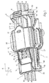
- Figure 1 shows a view in perspective of an electric connecting unit in accordance with the present invention in course of assembly;
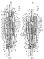
- Figure 2 shows a longitudinal section of the Figure 1 unit;
- Figure 3 shows a longitudinal section of the Figure 1 unit fully assembled;
- Figure 4 shows a section along line IV-IV in Figure 2;
- Figure 5 shows a section along line V-V in Figure 3;
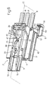
- Figure 6 shows a view in perspective of a first connector of the Figure 1 unit;
- Figure 7 shows a view in perspective of a second connector of the Figure 1 unit.
-
- With reference to Figures 1 to 5,
number 1 indicates as a whole an electric connecting unit comprising twoelectric connectors device 4 for click-on connectingconnectors - It should be stressed that the terms "top", "bottom", "front", "rear" and similar used in the following description are in now way limiting, and are used solely for the sake of clarity with reference to the position of
unit 1 shown in Figures 1 to 5. - Connector 2 (Figures 1 to 6) comprises a substantially parallelepiped-shaped
insulating casing 5 defining a number of - in the example shown, three - longitudinal throughcavities 6 arranged side by side in a direction B perpendicular to direction A, and for housing respective femaleelectric terminals 7 connected to respectiveelectric cables 8.Connector 2 also comprises main retaining means 9 for retaining eachterminal 7 in a correct insertion position insiderespective cavity 6; and auxiliary retaining means 10 for determining correct insertion ofterminals 7 insidecavities 6 and preventing withdrawal of the terminals. -
Casing 5 comprises a plate 11 (for the purpose explained later on) projecting frontwards - substantially as an extension of atop wall 12 ofcasing 5 parallel to directions A and B - and having, on the outside, on the opposite side tocavities 6, tworibs 13 parallel to direction A. - Connector 3 (Figures 1 to 5 and Figure 7) comprises an
insulating casing 14 having a substantially parallelepiped-shapedrear portion 15 defining a number of - in the example shown, three -longitudinal cavities 16 for housing respective maleelectric terminals 17 connected to respectiveelectric cables 18 and for connection tofemale terminals 7 ofconnector 2, and a hollow, substantially parallelepiped-shaped front portion 19 defining acompartment 20 forhousing connector 2 and which is complementary in shape tocasing 5 and communicates withcavities 16. Likeconnector 2,connector 3 also comprises main retaining means 25 for retaining eachterminal 17 in a correct insertion position insiderespective cavity 16; and auxiliary retaining means 26 for determining correct insertion ofterminals 17 insidecavities 16 and preventing withdrawal of the terminals. - More specifically,
portion 19 projects outwards on opposite sides ofportion 15 in a direction C perpendicular to directions A and B, and is connected toportion 15 by twowalls 27 perpendicular to direction A and forming an extension of an end wall ofcompartment 20. One ofwalls 27 has a shaped through opening 28 engaged, in the final assembly position ofconnectors plate 11, which projects fromcompartment 20 and is positioned contacting atop wall 29 ofportion 15. Insidecompartment 20,portion 19 also comprises twogrooves 30 parallel to direction A and which are engaged in sliding manner byribs 13 ofplate 11 when assemblingconnectors plate 11. - With particular reference to Figures 1, 6 and 7,
device 4 comprises amale member 31 located close to a front opening ofportion 19 and projecting integrally inwards ofcompartment 20 ofcasing 14 from a toplongitudinal wall 32 ofportion 19; and anelastic member 33, which projects longitudinally from an outer face ofwall 12 ofcasing 5, has aseat 34 for retainingmale member 31, and is flexible parallel to direction C to permit release ofconnectors connectors male member 31 cooperates in sliding manner, in direction A, withseat 34 to engageseat 34 in a position corresponding to the final assembly position ofconnectors - More specifically,
male member 31 is defined by a tooth comprising a wedge-shapedmain portion 35, which in turn is defined by opposite substantially longitudinal, convex lateral surfaces, and, sectioned in a plane perpendicular to direction C, is substantially ogival in shape, tapering towards a pointed front end facing the front opening ofportion 19. At the opposite end,male member 31 comprises twoprojections 36 projecting laterally fromportion 35 and defining, towards the pointed end ofportion 35,respective shoulders 37 substantially crosswise to direction A. More specifically,shoulders 37 slope slightly with respect to a plane perpendicular to direction A so as to converge towards the pointed end ofportion 35. At the end opposite the pointed end,male member 31 is defined by twosurfaces 41 substantially parallel toshoulders 37 and forming an obtuse dihedral angle. -
Elastic member 33 comprises two substantially parallellongitudinal arms 38, which are symmetrical with respect to an intermediate plane π ofconnector 2, form extensions ofribs 13, and each have one end integral with a front transverse edge ofwall 12. Respective free ends ofarms 38 are connected integrally by across member 39 projecting outwards fromcasing 14 ofconnector 3 in the final assembly position ofconnectors wall 12 to permit release ofconnectors -
Arms 38 comprise respectiveintermediate projections 40 symmetrical with respect to plane π, extending towards each other, and substantially in the form of right trapeziums with the oblique sides facing each other.Seat 34 has an axis parallel to direction A and lying in plane π, and is defined byprojections 40 and by respective portions ofarms 38 extending betweenprojections 40 andcross member 39. -
Arms 38 are flexible in a plane substantially perpendicular to direction C to permit insertion ofmale member 31 insideseat 34. - More specifically, each
projection 40 is defined by a lateralfirst surface 45 perpendicular to direction A and facingplate 11; by a lateralsecond surface 46 facingcross member 39 and sloping at the same angle asrespective surface 41 ofmale member 31; and by a substantially longitudinalthird surface 47 interposed betweensurfaces seat 34 increasing fromsurface 45 tosurface 46. -
Surfaces 45 define a front opening ofseat 34 and a temporary stop forshoulders 37 ofmale member 31 when connectingconnectors connectors shoulders 37past surfaces 45 and enablemale member 31 to assume the engaged position in whichsurfaces 41 rest againstsurfaces 46 ofseat 34. -
Surfaces 47 are so formed as to exert elastic thrust onmale member 31 to bringmale member 31 irreversibly into the engaged position asprojections 36 ofmale member 31 clickpast surfaces 45 when connectingconnectors - With reference to Figures 2 to 5, each
terminal 7 ofconnector 2 comprises a box-shapedfront contact portion 48; arear portion 49 for connection to respectiveelectric cable 8; and anintermediate portion 50 extending betweenportions - Each
terminal 7 is inserted insiderespective cavity 6 through arear opening 51 of the cavity, from whichcable 8 projects, and is positioned withcontact portion 48 facing a front opening 52 ofcavity 6. - Main retaining means 9 comprise, for each
terminal 7, aretaining seat 53 formed inintermediate portion 50 ofterminal 7; and an elastic lance 54, which projects insiderespective cavity 6, towardsfront opening 52, from abottom wall 42 ofcasing 5 parallel towall 12, and clicks ontoseat 53 by means of arespective tooth 55 to retainterminal 7 in the correct insertion position insidecavity 6. - Each lance 54 interacts with
respective terminal 7 so as to flex, parallel to direction C, between an undeformed configuration corresponding to a position in whichtooth 55 engagesrespective seat 53 andterminal 7 is inserted correctly insiderespective cavity 6, and a deformed configuration in which the lance is flexed away from the axis ofcavity 6. - Auxiliary retaining means 10 comprise a hatch-type
movable member 56 integral with and extending the full width ofcasing 5, and hinged to a rear end ofwall 42 to rotate between an open position permitting insertion ofterminals 7 insiderespective cavities 6, and a closed position, clicked ontocasing 5, to prevent withdrawal ofterminals 7 fromrespective cavities 6. - More specifically,
movable member 56, viewed from the side, is substantially L-shaped, and comprises a substantiallyflat base portion 57 hinged towall 42 and having, on the outside, two parallellongitudinal projections 58; and two pairs ofarms portion 57 and defining a number of U-shaped throughopenings 61. Whenmovable member 56 is in the closed position,portion 57 extends parallel towall 42, eacharm 59 is located between a pair ofadjacent cables 8, and eacharm 60 is located outwards of anend cable 8, so that eachopening 61 is engaged by a respectiveelectric cable 8 and has a lateral edge facing connectingportion 49 ofrespective terminal 7 in direction A, whichportion 49 projects radially with respect tocable 8. Whenmovable member 56 is in the closed position, the lateral edges ofopenings 61 therefore define respective stops forportions 49, to prevent withdrawal ofterminals 7 fromrespective cavities 6. -
Movable member 56 is clicked into the closed position oncasing 5 by retaining teeth 64 - projecting from a rear end of wall 42 - clicking inside respective end seats 63 onarms 60. - In the closed position of
movable member 56,projections 58 ofportion 57 cooperate in sliding manner with awall 32a,opposite wall 32, ofcompartment 20 to permit connection ofconnectors terminals 7 insiderespective cavity 6, interfere withwall 32a to prevent connection ofconnectors terminals 7 is inserted improperly insiderespective cavity 6, retainingteeth 64 are prevented from engaging seats 63 onarms 60 byportion 49 ofterminal 7 interacting with the lateral edge ofrespective opening 61. - With reference to Figures 2 to 5, each
terminal 17 ofconnector 3 comprises a box-shapedintermediate portion 66; acontact portion 67 projecting frontwards fromportion 66 and which fits insidecontact portion 48 of a respectivefemale terminal 7; and arear portion 68 for connection to respectiveelectric cable 18. - Each
terminal 17 is inserted insiderespective cavity 16 through arear opening 69 of the cavity, from whichcable 18 projects in use, and is positioned withcontact portion 67 projecting axially insidecompartment 20 through a front opening 70 ofcavity 16. - Main retaining means 25 comprise, for each
terminal 17, a retainingseat 71 formed inintermediate portion 66 ofterminal 17; and anelastic lance 72, which projects insiderespective cavity 16 fromwall 29 and parallel to direction A towardsfront opening 70, and clicks ontoseat 71 by means of a respective tooth 73 to retainterminal 17 in the correct insertion position insidecavity 16. - Each
lance 72 interacts withrespective terminal 17 so as to flex, parallel to direction C, between an undeformed configuration corresponding to a position in which tooth 73 engagesrespective seat 71 andterminal 17 is inserted correctly insiderespective cavity 16, and a deformed configuration in which the lance is flexed away from the axis ofcavity 16. - According to the present invention, each
lance 72 is located at a respective substantially rectangular through opening 74 inwall 29, and comprises anend projection 75 extending on the opposite side to tooth 73 and movable with lance 72 - by virtue of the interaction betweenlance 72 andrespective terminal 17, and, hence, of the position assumed byterminal 17 inside respective cavity 16 - between two work positions respectively disabling and enabling connection ofconnectors lance 72,projection 75 projects outwards ofwall 29 throughrespective opening 74 and interferes with the sliding movement ofplate 11 ofconnector 2 alongwall 29; whereas, in the enabling position corresponding to correct insertion ofterminal 17 insiderespective cavity 16 and to the undeformed configuration oflance 72,projection 75 engages opening 74 and is aligned with the outer edge ofopening 74 to enableplate 11 ofconnector 2 to slide alongwall 29. - More specifically,
projection 75 of eachlance 72 is substantially in the form of a right trapezium with the oblique side facing outwards ofwall 29; and eachlance 72 has a portion 65 connected towall 29 on the opposite side ofprojection 75 toconnector 2, so that, in the disabling position ofprojection 75, any attempt to force connection ofconnectors plate 11 jamming againstprojection 75, thus preventing attainment of the final assembly position. - As in
connector 2, auxiliary retaining means 26 comprise a hatch-typemovable member 76 integral with and extending the full width ofcasing 14, and hinged to a rear end ofwall 29 to rotate between an open position permitting insertion ofterminals 17 insiderespective cavities 16, and a closed position, clicked ontocasing 14, to prevent withdrawal ofterminals 17 fromrespective cavities 16. - More specifically,
movable member 76, viewed from the side, is substantially L-shaped, and comprises a substantially flatrectangular base portion 77 hinged towall 29; and two pairs ofarms portion 77 and defining a number of U-shaped throughopenings 80. Whenmovable member 76 is in the closed position,portion 77 extends parallel towall 29, eacharm 78 is located between a pair ofadjacent cables 18, and eacharm 79 is located outwards of anend cable 18, so that eachopening 80 is engaged by a respectiveelectric cable 18 and has a lateral edge facing connectingportion 68 ofrespective terminal 17 in direction A, whichportion 68 projects radially with respect tocable 18. Whenmovable member 76 is in the closed position, the lateral edges ofopenings 80 therefore define respective stops forportions 68, to prevent withdrawal ofterminals 17 fromrespective cavities 16. -
Movable member 76 is clicked into the closed position on casing 14 by retaining teeth 83 - projecting from a rear end of abottom wall 84, parallel to wall 29, of portion 15 - clicking insiderespective end seats 82 onarms 79. -
Unit 1 is assembled by slidingconnector 2 longitudinally in direction A insideportion 19 ofconnector 3, withterminals respective cavities respective lances 54, 72, and withmovable members respective casings 5, 14 (Figures 1, 2 and 4). - If any one of
terminals 7 is not inserted properly insiderespective cavity 6, the respective lance 54 is maintained byterminal 7 in the deformed configuration in whichtooth 55 is disengaged fromseat 53 and, on account of the lateral edge ofrespective opening 61 interacting with connectingportion 49 ofterminal 7,teeth 64 are prevented from engaging seats 63 onarms 60, thus preventingmovable member 56 from being clicked into the closed position. In which case,portion 57 ofmovable member 56 is inclined with respect towall 42, andprojections 58 interfere withwall 32a ofcompartment 20, thus preventing connection ofconnectors - Conversely, if
terminals 7 are all inserted correctly insiderespective cavities 6, i.e. withteeth 55 of lances 54 clicked insideseats 53, the lateral edges ofopenings 61 fit behindportions 49 ofterminals 7 andsurround cables 8, thus enablingmovable member 56 to be clicked into the closed position whereinportion 57 extends parallel to wall 42, andprojections 58 cooperate in sliding manner withwall 32a insidecompartment 20 to enable connection ofconnectors 2 and 3 (Figures 3 and 5). - If any one of
terminals 17 is not inserted properly insiderespective cavity 16, therespective lance 72 is maintained byterminal 17 in the deformed configuration in which tooth 73 is disengaged fromseat 71, andprojection 75 is in the disabling position projecting outwards ofwall 29 throughrespective opening 74 and interfering with the sliding movement ofplate 11 ofconnector 2 alongwall 29, thus preventing connection ofconnectors portion 68 of the improperly insertedterminal 17,teeth 83 are prevented from engagingseats 82 onarms 79, thus preventingmovable member 76 from being clicked into the closed position. - Conversely, if
terminals 17 are all inserted correctly insiderespective cavities 16, i.e. with teeth 73 oflances 72 clicked insideseats 71,projections 75 are in the enabling position engagingrespective openings 74, and are aligned with the outer edges ofopenings 74, thus enablingplate 11 ofconnector 2 to slide alongwall 29 and, hence, connection ofconnectors openings 80 fit behindportions 68 ofterminals 17 andsurround cables 18, thus enablingmovable member 76 to be clicked into the closed position (Figures 3 and 5). - As
connector 2 is slid longitudinally in direction A insidecompartment 20 ofconnector 3,male member 31 is inserted insideseat 34 ofelastic member 33; and, on account ofportion 35 ofmale member 31 increasing in section towardsprojections 36, the gradual insertion ofmale member 31 insideseat 34 elastically deformsarms 38, which part in the plane perpendicular to direction C. At the initial connection stage, the elastic reaction of arms 38 - by virtue of the shape of male member 31 - is such as to repelconnectors terminals 7 and/or 17 is not inserted properly insiderespective cavity projections 58 ofmovable member 56 interfere withwall 32a ofcompartment 20 and/orprojection 75 ofrespective lance 72 interferes withplate 11,connectors - Upon
shoulders 37 ofmale member 31 coming to rest againstrespective surfaces 45 ofprojections 40, surfaces 45 temporarily arrestmale member 31, so that additional thrust is required to elastically partarms 38, which are subjected to a transverse thrust component on account of the slope ofshoulders 37. If the thrust applied exceeds a threshold value defined by the geometry of the contacting surfaces and by the characteristics of the material used,projections 36 ofmale member 31 click past surfaces 45 to clickmale member 31 into the engaged position corresponding to the final assembly position ofconnectors - As
projections 36 click past surfaces 45 andarms 38 begin returning to the undeformed position, surfaces 47, by defining a portion ofseat 34 increasing in section towardscross member 39, exert thrust onmale member 31 to pushmale member 31 irreversibly into the engaged position. - To disconnect
connectors cross member 39 is simply pushed in direction C to releasesurfaces 46 ofprojections 40 fromrespective surfaces 41 ofmale member 31. - The advantages of
unit 1 andconnector 3 according to the present invention will be clear from the foregoing description. - In particular, if any one of
terminals 17 ofconnector 3 is not inserted properly insiderespective cavity 16, therespective lance 72 is maintained byterminal 17 in the deformed configuration, andprojection 75 projects outwards ofwall 29 to preventplate 11 ofconnector 2 from sliding alongwall 29 and, hence, connection ofelectric connectors movable member 76 is forced into the closed position, the presence of an improperly inserted terminal 17 would still be detected when assemblingconnector 3 toconnector 2. - The above characteristic, combined with
movable member 56 ofconnector 2 comprisingprojections 58 for preventing insertion ofconnector 2 insidecompartment 20 ofconnector 3 withmovable member 56 in other than the closed position (terminals 7 not properly inserted), provides for extremely safe connection and a high degree of reliability ofunit 1. - Finally, the resistance offered by
surfaces 45 ofelastic member 33 to insertion ofmale member 31 insideseat 34 ensures expulsion ofconnector 2 fromcompartment 20 in the event one ormore terminals respective cavities - Clearly, changes may be made to
unit 1 as described herein with out, however, departing from the scope of the present invention.
Claims (18)
- An electric connector (3) connectable in an assembly direction (A) to a complementary connector (2), and comprising:characterized in that said stop means (75) directly interfere with said complementary connector (2) in said first work position.an insulating casing (14) defining at least one cavity (16) having an axis parallel to said assembly direction (A) and for housing a respective electric terminal (17); andmain retaining means (25) for retaining said terminal (17) in a correct insertion position inside said cavity (16), and comprising at least one retaining member (72) associated with said cavity (16), movable to click onto retaining means (71) of said terminal (17), and having stop means (75) displaceable with the retaining member (72) itself, by virtue of the position assumed by said terminal (17) inside said cavity (16), between a first and a second work position to respectively disable and enable connection of said connector (3) to said complementary connector (2); said first work position corresponding to a release position of said retaining member (72) and said retaining means (71) and said second work position being assumed when said terminal (17) is in said correct insertion position inside said cavity (16),
- A connector as claimed in Claim 1, characterized in that said retaining member (72) projects inwards of said cavity (16) from a wall (29) of said casing (14) and in a direction substantially parallel to said assembly direction (A), and is located at a through opening (74) in said wall (29); and in that said stop means comprise a projection (75) carried by said retaining member (72), and which projects outwards from said wall (29) in said first work position so as to interfere with a coupling portion (11), cooperating in sliding manner with said wall (29), of said complementary connector (2).
- A connector as claimed in Claim 2, characterized in that said retaining member (72) comprises a connecting portion (65) connected to said wall (29) and located on the opposite side of said projection (75) with respect to said complementary connector (2), so as to determine, in said first work position of said projection (75), interference between said projection (75) and said coupling portion (11) of said complementary connector (2).
- A connector as claimed in Claim 2 or 3, characterized in that said projection (75) defines a free end of said retaining member (72).
- A connector as claimed in any one of Claims 2 to 4, characterized in that said projection (75) is substantially in the form of a right trapezium with the oblique side facing outwards of said wall (29).
- A connector as claimed in any one of Claims 2 to 5, characterized in that said retaining means comprise a retaining seat (71) formed in said terminal (17); and in that said retaining member (72) comprises a tooth (73) located on the opposite side to said projection (75), and which clicks onto said retaining seat (71) in said correct insertion position of said terminal (17) inside said cavity (16).
- A connector as claimed in any one of the foregoing Claims, characterized by comprising auxiliary retaining means (26) for ensuring said terminal (17) is in said correct insertion position inside said cavity (16), and for preventing-withdrawal of the terminal.
- An electric connecting unit (1) comprising a first and a second electric connector (3, 2) connectable mutually, in an assembly direction (A), in a final assembly position; said first connector (3) comprising:characterized in that said stop means (75) directly interfere with said second connector (2) in said first work position.a first insulating casing (14) defining at least one first cavity (16) having an axis parallel to said assembly direction (A) and for housing a first electric terminal (17); andfirst main retaining means (25) for retaining said first electric terminal (17) in a correct insertion position inside said first cavity (16), and comprising retaining means (71) defined by said first electric terminal (17), and at least one retaining member (72) associated with said first cavity (16), movable to click onto said retaining means (71) of said first electric terminal (17), and having stop means (75) displaceable with the retaining member (72) itself by virtue of the position assumed by said first electric terminal (17) inside said first cavity (16) between a first and a second work position to respectively disable and enable connection of said first and said second connector (3, 2); said first work position corresponding to a release position of said retaining member (72) and said retaining means (71) and said second work position being assumed when said first electric terminal (17) is in said correct insertion position inside said first cavity (16),
- A unit as claimed in Claim 8, characterized in that said retaining member (72) projects inwards of said first cavity (16) from a first wall (29) of said first insulating casing (14) and in a direction substantially parallel to said assembly direction (A), and is located at a through opening (74) in said first wall (29); and in that said stop means comprise a first projection (75) carried by said retaining member (72), and which projects outwards from said first wall (29) in said first work position so as to interfere with a coupling portion (11), cooperating in sliding manner with said first wall (29), of said second connector (2).
- A unit as claimed in Claim 9, characterized in that said retaining member (72) comprises a connecting portion (65) connected to said first wall (29) and located on the opposite side of said first projection (75) with respect to said second connector (2), so as to determine, in said first work position of said first projection (75), interference between said first projection (75) and said coupling portion (11) of said second connector (2).
- A unit as claimed in any one of Claims 8 to 10, characterized in that said first connector (3) comprises first auxiliary retaining means (26) for ensuring said first electric terminal (17) is in said correct insertion position inside said first cavity (16), and for preventing withdrawal of the first electric terminal (17).
- A unit as claimed in any one of Claims 8 to 11, characterized in that said second connector (2) comprises a second insulating casing (5) defining at least one second cavity (6) having an axis parallel to said assembly direction (A) and for housing a second electric terminal (7) connectable to said first electric terminal (17); second main retaining means (9) for retaining said second electric terminal (7) in a correct insertion position inside said second cavity (6); and second auxiliary retaining means (10) comprising at least one movable member (56) connectable to said second insulating casing (5) in a closed position to ensure said second electric terminal (7) is in said correct insertion position inside said second cavity (6), and to prevent withdrawal of the second electric terminal; said unit (1) comprising disabling means (58) for disabling connection of said first and said second connector (3, 2), and which are interposed between said movable member (56) and said first insulating casing (14), and are deactivated by the movable member (56) in said closed position.
- A unit as claimed in Claim 12, characterized in that said first insulating casing (14) defines a housing (20) for housing said second connector (2), and which is complementary in shape to said second insulating casing (5); and in that said movable member (56) is defined by a hatch-type member hinged to said second insulating casing (5) so as to rotate between an open position permitting insertion of said second electric terminal (7) inside said second cavity (6), and a closed position in which the hatch-type member clicks onto said second insulating casing (5) to prevent withdrawal of said second electric terminal (7) from said second cavity (6); said disabling means comprising at least one second projection (58) carried by said movable member (56) and which cooperates in sliding manner with a second wall (32a) of said housing (20) in said closed position of said movable member (56), and interferes with the second wall (32a) in positions of said movable member (56) other than said closed position.
- A unit as claimed in Claim 13, characterized in that said movable member (56), when viewed laterally, is substantially L-shaped, and comprises a substantially flat base portion (57) hinged to said second insulating casing (5) and having, on the outside, a pair of said second projections (58); and at least two arms (59, 60) projecting perpendicularly from said base portion (57) and defining a U-shaped through opening (61) which is engaged by an electric cable (8) connected to said second electric terminal (7); said base portion (57) and said second projections (58) being parallel to said assembly direction (A) in said closed position of said movable member (56), and being inclined with respect to said assembly direction (A) when said second electric terminal (7) is inserted incorrectly inside said second cavity (6).
- A unit as claimed in any one of Claims 8 to 14, characterized by comprising click-on connecting means (4) for click-on connecting said first and said second connector (3, 2), and which are defined by a retaining seat (34) carried by said second connector (2), and by a male member (31) carried by said first connector (3) and which, during connection of said first and said second connector (3, 2), cooperates in sliding manner, in said assembly direction (A), with said retaining seat (34) to engage said retaining seat (34) in an engaged position corresponding to said final assembly position of said first and said second connector (3, 2); said male member (31) having at least one lateral shoulder (37) substantially crosswise to said assembly direction (A); and said retaining seat (34) having for said shoulder (37) at least one mating surface (45) substantially crosswise to said assembly direction (A) and defining a temporary stop for said shoulder (37) during connection of said first and said second connector (3, 2), so that the force required to connect said first and said second connector (3, 2) must be increased to a threshold value sufficient to click said shoulder (37) past said mating surface (45) and enable said male member (31) to assume said engaged position.
- A unit as claimed in Claim 15, characterized in that at least one of said male member (31) and said retaining seat (34) is integral with an elastic member (33) projecting outwards from one (5) of said first and said second insulating casing (14, 5) and flexible in a direction (C) crosswise to said assembly direction (A) to permit release of said first and said second connector (3, 2).
- A unit as claimed in Claim 15 or 16, characterized in that said male member (31) is defined by a tooth projecting from a third wall (32) of said first insulating casing (14), and comprises a main portion (35), and a pair of lateral third projections (36) defining respective said shoulders (37); said elastic member (33) extending from said second insulating casing (5) and comprising a pair of elastic arms (38) defining said retaining seat (34) and respective said mating surfaces (45) for said shoulders (37).
- A unit as claimed in any one of Claims 8 to 17, characterized in that said first and said second insulating casing (14, 5) comprise a number of said first and said second cavities (16, 6) for respective said first and said second electric terminals (17, 7).
Applications Claiming Priority (2)
| Application Number | Priority Date | Filing Date | Title |
|---|---|---|---|
| IT1998TO000910A IT1305141B1 (en) | 1998-10-27 | 1998-10-27 | ELECTRIC CONNECTOR AND ELECTRICAL CONNECTION UNIT PROVIDED WITH SUCH CONNECTOR. |
| ITTO980910 | 1998-10-27 |
Publications (3)
| Publication Number | Publication Date |
|---|---|
| EP1001494A2 EP1001494A2 (en) | 2000-05-17 |
| EP1001494A3 EP1001494A3 (en) | 2000-09-06 |
| EP1001494B1 true EP1001494B1 (en) | 2002-12-18 |
Family
ID=11417139
Family Applications (1)
| Application Number | Title | Priority Date | Filing Date |
|---|---|---|---|
| EP99121330A Expired - Lifetime EP1001494B1 (en) | 1998-10-27 | 1999-10-26 | Electrical connector with terminal insertion detection means |
Country Status (5)
| Country | Link |
|---|---|
| US (1) | US6220894B1 (en) |
| EP (1) | EP1001494B1 (en) |
| AT (1) | ATE230167T1 (en) |
| DE (1) | DE69904557T2 (en) |
| IT (1) | IT1305141B1 (en) |
Families Citing this family (2)
| Publication number | Priority date | Publication date | Assignee | Title |
|---|---|---|---|---|
| DE10302945B4 (en) * | 2003-01-24 | 2010-08-12 | Leopold Kostal Gmbh & Co. Kg | Electrical plug-in connector |
| ES2359891T3 (en) † | 2007-11-22 | 2011-05-27 | Electrolux Home Products Corporation N.V. | APPLIANCE APPLIANCE. |
Family Cites Families (6)
| Publication number | Priority date | Publication date | Assignee | Title |
|---|---|---|---|---|
| US4557542A (en) * | 1984-06-11 | 1985-12-10 | Amp Incorporated | Connector with means for retaining terminals and verifying seating |
| JPS62190672A (en) * | 1986-02-18 | 1987-08-20 | 矢崎総業株式会社 | Connector housing |
| JP2644548B2 (en) * | 1988-09-20 | 1997-08-25 | 日本エー・エム・ピー株式会社 | Electrical connector |
| US5281168A (en) * | 1992-11-20 | 1994-01-25 | Molex Incorporated | Electrical connector with terminal position assurance system |
| JPH07211381A (en) * | 1994-01-19 | 1995-08-11 | Yazaki Corp | Locking method and structure for double locking connector |
| US5520553A (en) * | 1994-12-08 | 1996-05-28 | Molex Incorporated | Connector with a front end mounted terminal position assurance system |
-
1998
- 1998-10-27 IT IT1998TO000910A patent/IT1305141B1/en active
-
1999
- 1999-10-26 AT AT99121330T patent/ATE230167T1/en not_active IP Right Cessation
- 1999-10-26 DE DE69904557T patent/DE69904557T2/en not_active Expired - Lifetime
- 1999-10-26 US US09/426,974 patent/US6220894B1/en not_active Expired - Lifetime
- 1999-10-26 EP EP99121330A patent/EP1001494B1/en not_active Expired - Lifetime
Also Published As
| Publication number | Publication date |
|---|---|
| EP1001494A3 (en) | 2000-09-06 |
| EP1001494A2 (en) | 2000-05-17 |
| US6220894B1 (en) | 2001-04-24 |
| DE69904557T2 (en) | 2003-09-25 |
| ITTO980910A1 (en) | 2000-04-27 |
| IT1305141B1 (en) | 2001-04-10 |
| ATE230167T1 (en) | 2003-01-15 |
| DE69904557D1 (en) | 2003-01-30 |
Similar Documents
| Publication | Publication Date | Title |
|---|---|---|
| US5672073A (en) | Connector having engagement detecting device | |
| US6287139B1 (en) | Connector | |
| EP1054481B1 (en) | A connector | |
| US6386898B1 (en) | Connector fitting construction | |
| KR20170136991A (en) | Electrical connector assembly with improved locking device | |
| CN110571567A (en) | staged release electrical connector assembly | |
| US5910028A (en) | Connector | |
| US6039589A (en) | Electrical connector with a shunt incorporated into a secondary locking member | |
| US7121866B2 (en) | Electric connecter | |
| EP0871253B1 (en) | Lock detection connector | |
| US7578709B2 (en) | Contact locking device for an electric connector and electric connector containing said device | |
| EP1001494B1 (en) | Electrical connector with terminal insertion detection means | |
| US5928014A (en) | Electrical connector having a pair of connector housings | |
| EP1225659A2 (en) | Electrical connecting unit | |
| EP0797851B1 (en) | Electric connector | |
| EP0967686B1 (en) | Electrical connector with terminal position assurance device | |
| US7335061B2 (en) | Electric connector | |
| US5820410A (en) | Electric connector | |
| US10950967B2 (en) | Electric terminal housing with a terminal lock | |
| CN113557641B (en) | Connector position assurance member | |
| EP1257007B1 (en) | Electric connector | |
| EP4228100A1 (en) | Connector assembly with an unseated terminal detection feature | |
| EP1005113B1 (en) | Electric connector | |
| EP0809871B1 (en) | Electric connector | |
| WO2008078156A1 (en) | Electrical connector with improved secondary locking means |
Legal Events
| Date | Code | Title | Description |
|---|---|---|---|
| PUAI | Public reference made under article 153(3) epc to a published international application that has entered the european phase |
Free format text: ORIGINAL CODE: 0009012 |
|
| AK | Designated contracting states |
Kind code of ref document: A2 Designated state(s): AT BE CH CY DE DK ES FI FR GB GR IE IT LI LU MC NL PT SE |
|
| AX | Request for extension of the european patent |
Free format text: AL;LT;LV;MK;RO;SI |
|
| PUAL | Search report despatched |
Free format text: ORIGINAL CODE: 0009013 |
|
| AK | Designated contracting states |
Kind code of ref document: A3 Designated state(s): AT BE CH CY DE DK ES FI FR GB GR IE IT LI LU MC NL PT SE |
|
| AX | Request for extension of the european patent |
Free format text: AL;LT;LV;MK;RO;SI |
|
| RIC1 | Information provided on ipc code assigned before grant |
Free format text: 7H 01R 13/42 A, 7H 01R 13/627 B, 7H 01R 13/64 B, 7B 60R 21/00 B, 7H 01R 13/422 B, 7B 60R 21/01 B |
|
| 17P | Request for examination filed |
Effective date: 20010208 |
|
| AKX | Designation fees paid |
Free format text: AT BE CH CY DE DK ES FI FR GB GR IE IT LI LU MC NL PT SE |
|
| 17Q | First examination report despatched |
Effective date: 20010523 |
|
| GRAG | Despatch of communication of intention to grant |
Free format text: ORIGINAL CODE: EPIDOS AGRA |
|
| GRAG | Despatch of communication of intention to grant |
Free format text: ORIGINAL CODE: EPIDOS AGRA |
|
| GRAH | Despatch of communication of intention to grant a patent |
Free format text: ORIGINAL CODE: EPIDOS IGRA |
|
| GRAH | Despatch of communication of intention to grant a patent |
Free format text: ORIGINAL CODE: EPIDOS IGRA |
|
| GRAA | (expected) grant |
Free format text: ORIGINAL CODE: 0009210 |
|
| RAP1 | Party data changed (applicant data changed or rights of an application transferred) |
Owner name: FCI |
|
| AK | Designated contracting states |
Kind code of ref document: B1 Designated state(s): AT BE CH CY DE DK ES FI FR GB GR IE IT LI LU MC NL PT SE |
|
| PG25 | Lapsed in a contracting state [announced via postgrant information from national office to epo] |
Ref country code: NL Free format text: LAPSE BECAUSE OF FAILURE TO SUBMIT A TRANSLATION OF THE DESCRIPTION OR TO PAY THE FEE WITHIN THE PRESCRIBED TIME-LIMIT Effective date: 20021218 Ref country code: LI Free format text: LAPSE BECAUSE OF FAILURE TO SUBMIT A TRANSLATION OF THE DESCRIPTION OR TO PAY THE FEE WITHIN THE PRESCRIBED TIME-LIMIT Effective date: 20021218 Ref country code: IT Free format text: LAPSE BECAUSE OF FAILURE TO SUBMIT A TRANSLATION OF THE DESCRIPTION OR TO PAY THE FEE WITHIN THE PRESCRIBED TIME-LIMIT;WARNING: LAPSES OF ITALIAN PATENTS WITH EFFECTIVE DATE BEFORE 2007 MAY HAVE OCCURRED AT ANY TIME BEFORE 2007. THE CORRECT EFFECTIVE DATE MAY BE DIFFERENT FROM THE ONE RECORDED. Effective date: 20021218 Ref country code: GR Free format text: LAPSE BECAUSE OF FAILURE TO SUBMIT A TRANSLATION OF THE DESCRIPTION OR TO PAY THE FEE WITHIN THE PRESCRIBED TIME-LIMIT Effective date: 20021218 Ref country code: FI Free format text: LAPSE BECAUSE OF FAILURE TO SUBMIT A TRANSLATION OF THE DESCRIPTION OR TO PAY THE FEE WITHIN THE PRESCRIBED TIME-LIMIT Effective date: 20021218 Ref country code: CH Free format text: LAPSE BECAUSE OF FAILURE TO SUBMIT A TRANSLATION OF THE DESCRIPTION OR TO PAY THE FEE WITHIN THE PRESCRIBED TIME-LIMIT Effective date: 20021218 Ref country code: BE Free format text: LAPSE BECAUSE OF FAILURE TO SUBMIT A TRANSLATION OF THE DESCRIPTION OR TO PAY THE FEE WITHIN THE PRESCRIBED TIME-LIMIT Effective date: 20021218 Ref country code: AT Free format text: LAPSE BECAUSE OF FAILURE TO SUBMIT A TRANSLATION OF THE DESCRIPTION OR TO PAY THE FEE WITHIN THE PRESCRIBED TIME-LIMIT Effective date: 20021218 |
|
| REF | Corresponds to: |
Ref document number: 230167 Country of ref document: AT Date of ref document: 20030115 Kind code of ref document: T |
|
| REG | Reference to a national code |
Ref country code: GB Ref legal event code: FG4D |
|
| REG | Reference to a national code |
Ref country code: CH Ref legal event code: EP |
|
| REG | Reference to a national code |
Ref country code: IE Ref legal event code: FG4D |
|
| REF | Corresponds to: |
Ref document number: 69904557 Country of ref document: DE Date of ref document: 20030130 Kind code of ref document: P Ref document number: 69904557 Country of ref document: DE Date of ref document: 20030130 |
|
| PG25 | Lapsed in a contracting state [announced via postgrant information from national office to epo] |
Ref country code: SE Free format text: LAPSE BECAUSE OF FAILURE TO SUBMIT A TRANSLATION OF THE DESCRIPTION OR TO PAY THE FEE WITHIN THE PRESCRIBED TIME-LIMIT Effective date: 20030318 Ref country code: PT Free format text: LAPSE BECAUSE OF FAILURE TO SUBMIT A TRANSLATION OF THE DESCRIPTION OR TO PAY THE FEE WITHIN THE PRESCRIBED TIME-LIMIT Effective date: 20030318 Ref country code: DK Free format text: LAPSE BECAUSE OF FAILURE TO SUBMIT A TRANSLATION OF THE DESCRIPTION OR TO PAY THE FEE WITHIN THE PRESCRIBED TIME-LIMIT Effective date: 20030318 |
|
| PG25 | Lapsed in a contracting state [announced via postgrant information from national office to epo] |
Ref country code: ES Free format text: LAPSE BECAUSE OF FAILURE TO SUBMIT A TRANSLATION OF THE DESCRIPTION OR TO PAY THE FEE WITHIN THE PRESCRIBED TIME-LIMIT Effective date: 20030627 |
|
| REG | Reference to a national code |
Ref country code: CH Ref legal event code: PL |
|
| ET | Fr: translation filed | ||
| PLBE | No opposition filed within time limit |
Free format text: ORIGINAL CODE: 0009261 |
|
| STAA | Information on the status of an ep patent application or granted ep patent |
Free format text: STATUS: NO OPPOSITION FILED WITHIN TIME LIMIT |
|
| PG25 | Lapsed in a contracting state [announced via postgrant information from national office to epo] |
Ref country code: LU Free format text: LAPSE BECAUSE OF NON-PAYMENT OF DUE FEES Effective date: 20031026 Ref country code: GB Free format text: LAPSE BECAUSE OF NON-PAYMENT OF DUE FEES Effective date: 20031026 Ref country code: CY Free format text: LAPSE BECAUSE OF FAILURE TO SUBMIT A TRANSLATION OF THE DESCRIPTION OR TO PAY THE FEE WITHIN THE PRESCRIBED TIME-LIMIT Effective date: 20031026 |
|
| PG25 | Lapsed in a contracting state [announced via postgrant information from national office to epo] |
Ref country code: IE Free format text: LAPSE BECAUSE OF NON-PAYMENT OF DUE FEES Effective date: 20031027 |
|
| PG25 | Lapsed in a contracting state [announced via postgrant information from national office to epo] |
Ref country code: MC Free format text: LAPSE BECAUSE OF NON-PAYMENT OF DUE FEES Effective date: 20031031 |
|
| 26N | No opposition filed |
Effective date: 20030919 |
|
| GBPC | Gb: european patent ceased through non-payment of renewal fee |
Effective date: 20031026 |
|
| REG | Reference to a national code |
Ref country code: IE Ref legal event code: MM4A |
|
| REG | Reference to a national code |
Ref country code: FR Ref legal event code: CA |
|
| REG | Reference to a national code |
Ref country code: FR Ref legal event code: TP |
|
| REG | Reference to a national code |
Ref country code: FR Ref legal event code: GC |
|
| REG | Reference to a national code |
Ref country code: DE Ref legal event code: R082 Ref document number: 69904557 Country of ref document: DE Representative=s name: BEETZ & PARTNER MBB PATENT- UND RECHTSANWAELTE, DE Effective date: 20120419 Ref country code: DE Ref legal event code: R082 Ref document number: 69904557 Country of ref document: DE Representative=s name: BEETZ & PARTNER MBB PATENTANWAELTE, DE Effective date: 20120419 Ref country code: DE Ref legal event code: R082 Ref document number: 69904557 Country of ref document: DE Representative=s name: BEETZ & PARTNER PATENT- UND RECHTSANWAELTE, DE Effective date: 20120419 Ref country code: DE Ref legal event code: R081 Ref document number: 69904557 Country of ref document: DE Owner name: DELPHI INTERNATIONAL OPERATIONS LUXEMBOURG S.A, LU Free format text: FORMER OWNER: FCI, PARIS, FR Effective date: 20120419 |
|
| REG | Reference to a national code |
Ref country code: DE Ref legal event code: R082 Ref document number: 69904557 Country of ref document: DE Representative=s name: BEETZ & PARTNER MBB PATENT- UND RECHTSANWAELTE, DE Effective date: 20120628 Ref country code: DE Ref legal event code: R082 Ref document number: 69904557 Country of ref document: DE Representative=s name: BEETZ & PARTNER MBB PATENTANWAELTE, DE Effective date: 20120628 Ref country code: DE Ref legal event code: R082 Ref document number: 69904557 Country of ref document: DE Representative=s name: BEETZ & PARTNER PATENT- UND RECHTSANWAELTE, DE Effective date: 20120628 Ref country code: DE Ref legal event code: R081 Ref document number: 69904557 Country of ref document: DE Owner name: DELPHI INTERNATIONAL OPERATIONS LUXEMBOURG S.A, LU Free format text: FORMER OWNER: FCI, GUYANCOURT, FR Effective date: 20120628 |
|
| REG | Reference to a national code |
Ref country code: FR Ref legal event code: TP Owner name: DELPHI INTERNATIONAL OPERATIONS LUXEMBOURG S.A, LU Effective date: 20140715 |
|
| REG | Reference to a national code |
Ref country code: DE Ref legal event code: R082 Ref document number: 69904557 Country of ref document: DE Representative=s name: BEETZ & PARTNER PATENT- UND RECHTSANWAELTE, DE |
|
| REG | Reference to a national code |
Ref country code: DE Ref legal event code: R082 Ref document number: 69904557 Country of ref document: DE Representative=s name: BEETZ & PARTNER MBB PATENT- UND RECHTSANWAELTE, DE Effective date: 20141106 Ref country code: DE Ref legal event code: R082 Ref document number: 69904557 Country of ref document: DE Representative=s name: BEETZ & PARTNER MBB PATENTANWAELTE, DE Effective date: 20141106 Ref country code: DE Ref legal event code: R082 Ref document number: 69904557 Country of ref document: DE Representative=s name: BEETZ & PARTNER PATENT- UND RECHTSANWAELTE, DE Effective date: 20141106 Ref country code: DE Ref legal event code: R081 Ref document number: 69904557 Country of ref document: DE Owner name: DELPHI INTERNATIONAL OPERATIONS LUXEMBOURG S.A, LU Free format text: FORMER OWNER: FCI AUTOMOTIVE HOLDING, GUYANCOURT, FR Effective date: 20141106 |
|
| REG | Reference to a national code |
Ref country code: FR Ref legal event code: PLFP Year of fee payment: 17 |
|
| REG | Reference to a national code |
Ref country code: FR Ref legal event code: PLFP Year of fee payment: 18 |
|
| REG | Reference to a national code |
Ref country code: FR Ref legal event code: PLFP Year of fee payment: 19 |
|
| REG | Reference to a national code |
Ref country code: FR Ref legal event code: PLFP Year of fee payment: 20 |
|
| REG | Reference to a national code |
Ref country code: DE Ref legal event code: R082 Ref document number: 69904557 Country of ref document: DE Ref country code: DE Ref legal event code: R081 Ref document number: 69904557 Country of ref document: DE Owner name: APTIV TECHNOLOGIES LIMITED, BB Free format text: FORMER OWNER: DELPHI INTERNATIONAL OPERATIONS LUXEMBOURG S.A R.L., BASCHARAGE, LU |
|
| PGFP | Annual fee paid to national office [announced via postgrant information from national office to epo] |
Ref country code: DE Payment date: 20181029 Year of fee payment: 20 |
|
| PGFP | Annual fee paid to national office [announced via postgrant information from national office to epo] |
Ref country code: FR Payment date: 20181025 Year of fee payment: 20 |
|
| REG | Reference to a national code |
Ref country code: DE Ref legal event code: R071 Ref document number: 69904557 Country of ref document: DE |