EP1074723A2 - Direct-fuel-injection-type spark-ignition internal combustion engine and method of controlling the internal combustion engine - Google Patents
Direct-fuel-injection-type spark-ignition internal combustion engine and method of controlling the internal combustion engine Download PDFInfo
- Publication number
- EP1074723A2 EP1074723A2 EP00116802A EP00116802A EP1074723A2 EP 1074723 A2 EP1074723 A2 EP 1074723A2 EP 00116802 A EP00116802 A EP 00116802A EP 00116802 A EP00116802 A EP 00116802A EP 1074723 A2 EP1074723 A2 EP 1074723A2
- Authority
- EP
- European Patent Office
- Prior art keywords
- passage
- fuel
- cylinder bore
- coolant
- cylinder
- Prior art date
- Legal status (The legal status is an assumption and is not a legal conclusion. Google has not performed a legal analysis and makes no representation as to the accuracy of the status listed.)
- Granted
Links
Images



Classifications
-
- F—MECHANICAL ENGINEERING; LIGHTING; HEATING; WEAPONS; BLASTING
- F02—COMBUSTION ENGINES; HOT-GAS OR COMBUSTION-PRODUCT ENGINE PLANTS
- F02F—CYLINDERS, PISTONS OR CASINGS, FOR COMBUSTION ENGINES; ARRANGEMENTS OF SEALINGS IN COMBUSTION ENGINES
- F02F3/00—Pistons
- F02F3/26—Pistons having combustion chamber in piston head
-
- F—MECHANICAL ENGINEERING; LIGHTING; HEATING; WEAPONS; BLASTING
- F02—COMBUSTION ENGINES; HOT-GAS OR COMBUSTION-PRODUCT ENGINE PLANTS
- F02B—INTERNAL-COMBUSTION PISTON ENGINES; COMBUSTION ENGINES IN GENERAL
- F02B17/00—Engines characterised by means for effecting stratification of charge in cylinders
- F02B17/005—Engines characterised by means for effecting stratification of charge in cylinders having direct injection in the combustion chamber
-
- F—MECHANICAL ENGINEERING; LIGHTING; HEATING; WEAPONS; BLASTING
- F01—MACHINES OR ENGINES IN GENERAL; ENGINE PLANTS IN GENERAL; STEAM ENGINES
- F01P—COOLING OF MACHINES OR ENGINES IN GENERAL; COOLING OF INTERNAL-COMBUSTION ENGINES
- F01P3/00—Liquid cooling
- F01P3/02—Arrangements for cooling cylinders or cylinder heads
- F01P2003/021—Cooling cylinders
-
- F—MECHANICAL ENGINEERING; LIGHTING; HEATING; WEAPONS; BLASTING
- F01—MACHINES OR ENGINES IN GENERAL; ENGINE PLANTS IN GENERAL; STEAM ENGINES
- F01P—COOLING OF MACHINES OR ENGINES IN GENERAL; COOLING OF INTERNAL-COMBUSTION ENGINES
- F01P3/00—Liquid cooling
- F01P3/02—Arrangements for cooling cylinders or cylinder heads
- F01P2003/027—Cooling cylinders and cylinder heads in parallel
-
- F—MECHANICAL ENGINEERING; LIGHTING; HEATING; WEAPONS; BLASTING
- F01—MACHINES OR ENGINES IN GENERAL; ENGINE PLANTS IN GENERAL; STEAM ENGINES
- F01P—COOLING OF MACHINES OR ENGINES IN GENERAL; COOLING OF INTERNAL-COMBUSTION ENGINES
- F01P7/00—Controlling of coolant flow
- F01P7/14—Controlling of coolant flow the coolant being liquid
- F01P7/16—Controlling of coolant flow the coolant being liquid by thermostatic control
- F01P7/165—Controlling of coolant flow the coolant being liquid by thermostatic control characterised by systems with two or more loops
-
- F—MECHANICAL ENGINEERING; LIGHTING; HEATING; WEAPONS; BLASTING
- F02—COMBUSTION ENGINES; HOT-GAS OR COMBUSTION-PRODUCT ENGINE PLANTS
- F02B—INTERNAL-COMBUSTION PISTON ENGINES; COMBUSTION ENGINES IN GENERAL
- F02B75/00—Other engines
- F02B75/12—Other methods of operation
- F02B2075/125—Direct injection in the combustion chamber for spark ignition engines, i.e. not in pre-combustion chamber
-
- Y—GENERAL TAGGING OF NEW TECHNOLOGICAL DEVELOPMENTS; GENERAL TAGGING OF CROSS-SECTIONAL TECHNOLOGIES SPANNING OVER SEVERAL SECTIONS OF THE IPC; TECHNICAL SUBJECTS COVERED BY FORMER USPC CROSS-REFERENCE ART COLLECTIONS [XRACs] AND DIGESTS
- Y02—TECHNOLOGIES OR APPLICATIONS FOR MITIGATION OR ADAPTATION AGAINST CLIMATE CHANGE
- Y02T—CLIMATE CHANGE MITIGATION TECHNOLOGIES RELATED TO TRANSPORTATION
- Y02T10/00—Road transport of goods or passengers
- Y02T10/10—Internal combustion engine [ICE] based vehicles
- Y02T10/12—Improving ICE efficiencies
Definitions
- the invention relates to direct-fuel-injection-type spark-ignition internal combustion engines and to methods of controlling the internal combustion engine. More particularly, the invention relates to direct-fuel-injection-type spark-ignition internal combustion engines which effectively gasify fuel that has adhered to a cylinder bore and to methods of controlling the internal combustion engine.
- a direct-fuel-injection-type spark-ignition internal combustion engine has a fuel injection valve which directly injects fuel into a cylinder.
- fuel injection valve which directly injects fuel into a cylinder.
- fuel injected into a cylinder in the latter half of a compression stroke is gasified, and a combustible mixture with good ignitability is formed only in the neighborhood of an ignition plug at the time of ignition.
- stratified charge combustion wherein a lean mixture can burn is realized in the cylinder as a whole.
- the fuel injection valve is disposed at a periphery of an upper section of a cylinder so as not to interfere with intake and exhaust ports or an ignition plug located in the upper section of the cylinder.
- fuel injected from the fuel injection valve is deflected towards an area in the neighborhood of the ignition plug by means of a cavity formed in a top face of a piston.
- fuel is injected diagonally downward from the fuel injection valve so that fuel injected in the latter half of a compression stroke travels into the cavity at a piston position at the time of the injection.
- the invention aims to effectively gasify this adherent fuel.
- a first aspect of the invention provides a direct-fuel-injection-type spark-ignition internal combustion engine comprising a fuel injection valve which has a nozzle hole directed towards a portion opposed to the nozzle hole in a lower section of the cylinder bore so that fuel can be injected from an upper section of the cylinder into a cavity formed in a top face of a piston, and a cooler which cools the cylinder bore.
- the cooler cools the cylinder bore so as to suppress a fall in temperature of at least one area of the cylinder bore adjacent to the impingement portion in comparison with a fall in temperature of the other area of the cylinder bore than at least one area adjacent to the impingement portion.
- the cooler may have a first cooling portion and a second cooling portion.
- the first cooling portion cools an area close to the upper section of the cylinder bore.
- the second cooling portion cools at least an area close to the portion opposed to the nozzle hole in the lower section of the cylinder bore.
- the second cooling portion has a lower cooling capacity than the first cooling portion.
- the cooler includes a coolant passage, and the coolant passage in an area close to the portion opposed to the nozzle hole is smaller in cross-section than the coolant passage in an area close to the upper section of the cylinder bore. Because of this construction, the cooler located at least in the area close to the portion opposed to the nozzle hole in the lower section of the cylinder bore has a lower cooling capacity than the cooler located in the area close to the upper section of the cylinder bore. Therefore, the occurrence of overheating is prevented by sufficiently cooling the upper section of the cylinder bore. Even if fuel injected in the latter half of an intake stroke during homogeneous combustion-collides with the partion opposed to the nozzle hole in the cylinder bore and adheres thereto, the adherent fuel can be effectively gasified.
- the cooler is provided in an area close to the upper section of the cylinder bore, there may be no such cooler provided at least in an area close to the portion opposed to the nozzle hole in the lower section of the cylinder bore. Therefore, the occurrence of overheating is prevented by sufficiently cooling the upper section of the cylinder bore. Even if fuel injected in the latter half of an intake stroke during homogeneous combustion collides with the portion opposed to the nozzle hole in the cylinder bore and adheres thereto, this adherent fuel can be effectively gasified.
- the cooler may include the coolant passage having a first passage extending at least in an area close to the portion opposed to the nozzle hole in the lower section of the cylinder bore and a second passage extending at least in an area close to the upper section of the cylinder bore.
- a control valve is disposed in the first passage.
- the first passage is independent of the second passage.
- the cooler includes a coolant flow passage having a first passage extending in an area close to a side opposed to a nozzle hole of the fuel injection valve in the cylinder bore and a second passage extending in an area close to a side opposite the side opposed to the fuel injection valve in the cylinder bore.
- a control valve is disposed in the first passage.
- the first passage is independent of the second passage.
- the cooler may include a coolant passage having a first passage extending in an area close to a side opposed to a nozzle hole of the fuel injection valve in at least two of the cylinder bores and a second passage extending in an area close to a side opposite the side opposed to the nozzle hole of the fuel injection valve in the at least two cylinder bores.
- a coolant inlet portion is provided at one end of the second passage.
- a coolant outlet portion is provided at one end of the first passage.
- the other end of the first passage communicates with the other end of the second passage.
- There is provided a communication passage which extends between the two cylinder bores and through which the first passage communicates with the second passage.
- a control valve is provided in the communication passage.
- an opening degree of the control valve is reduced in comparison with an opening degree of the control valve during the stratified charge combustion, whereby an amount of coolant flowing through the communication passage is reduced.
- high-temperature coolant which has flowed through the second passage during homogeneous combustion and cooled the cylinder bores on a side opposite the side opposed to the nozzle hole of the fuel injection valve, flows through the first passage.
- the cylinder bores on the side opposed to the fuel injection valve are not sufficiently cooled. Even if fuel injected in the latter half of an intake stroke collides with the cylinder bores on the side opposed to the nozzle hole of the fuel injection valve and adheres thereto, this adherent fuel can be effectively gasified.
- a cylinder bore is cooled, and a fall in temperature at least in an area close to the portion opposed to the nozzle hole in the lower section of the cylinder bore is suppressed in comparison with a fall in temperature in an area close to the upper section of the cylinder bore.
- a cylinder bore is cooled, and a fall in temperature in an area close to a side opposite a side opposed to the nozzle hole of the fuel injection valve in the cylinder bore is suppressed in comparison with a fall in temperature in an area close to the side opposed to the nozzle hole of the fuel injection valve in the cylinder bore.
- the occurrence of overheating is prevented by sufficiently cooling the upper section of the cylinder bore. Even if fuel injected in the latter half of an intake stroke during homogeneous combustion collides with the portion opposed to the nozzle hole in the cylinder bore and adheres thereto, the adherent fuel can be effectively gasified.
- Fig. 1 schematically shows a longitudinal section of a direct-fuel-injection-type spark-ignition internal combustion engine in accordance with a first embodiment of the present invention.
- an intake port 1 and an exhaust port 2 are disposed in an upper section of a cylinder.
- the intake port 1 leads to the cylinder through an intake valve 3, and the exhaust port 2 leads to the cylinder through an exhaust valve 4.
- a piston 5 is disposed in the cylinder, and a recessed cavity 5a is formed in a top face of the piston 5.
- An ignition plug 6 is disposed substantially at the center of an upper section of a combustion chamber.
- a fuel injection valve 7 for directly injecting fuel into the cylinder from the periphery of the upper section of the cylinder is disposed to circumvent the intake port 1 and the exhaust port 2.
- the fuel injection valve 7 is disposed on the side of the intake valve which is at a relatively low temperature due to the flow of intake air.
- the fuel injection valve 7 has a slit-like nozzle hole and injects fuel in the shape of a laterally extending fan with a small thickness.
- the invention is not limited to this injection valve structure. That is, the fuel injection valve 7 may be designed to inject fuel in the shape of a circular cone or a column, for example.
- the fuel injection valve 7 injects fuel in the latter half of a compression stroke so that the fuel is introduced into the cavity 5a formed in the top face of the piston 5.
- the fuel that has just been injected is liquid, it proceeds along a bottom face of the cavity 5a, and is gasified by the time of introduction into an area in the neighborhood of the ignition plug 6, and turns into a combustible mixture with good ignitability at the time of ignition.
- Fuel spray in the shape of a laterally extending fan with a small thickness stretches out in the width direction when proceeding along the bottom face of the cavity 5a.
- this fuel spray can effectively absorb heat from a large area of the bottom face of the cavity 5a.
- a lateral wall of the cavity 5a opposed to the fuel injection valve is in the shape of an arc in a plan view.
- a central portion of fuel that has stretched out in the width direction above the bottom face of the cavity 5a is vested with an upward velocity component and proceeds toward the area in the neighborhood of the ignition plug 6.
- fuel spray in the shape of a laterally extending fan with a small thickness can form a combustible mixture with better gasification properties in the neighborhood of the ignition plug 6 in comparison with fuel spray in the shape of a circular cone as in the related art.
- the fuel injection valve 7 is designed to inject fuel diagonally downwards so that fuel injected in the latter half of a compression stroke is directed into the cavity 5a at a piston position at the time of the injection.
- fuel injected in the latter half of an intake stroke collides with a cylinder bore portion 10a opposed to the nozzle hole of the fuel injection valve in a lower section of the cylinder bore 10, as indicated by an alternate long and short dash line in Fig. 1.
- Portion 10a is also referred to as the "impingement portion" herein.
- a portion of the fuel colliding with the cylinder bore 10 adheres to the cylinder bore. If the entire cylinder bore 10 has been cooled by coolant, the adherent fuel is not sufficiently gasified, resides where it is, and does not contribute to combustion. Thus, it is necessary to increase a fuel injection amount to compensate for the adherent fuel. This causes problems such as deterioration of fuel consumption rate and an increase in frictional force between the cylinder bore 10 and the piston 5 due to dilution of engine oil by the adherent fuel.
- a coolant passage for cooling the cylinder bore 10 is composed of upper coolant pass.ages 11A, 11B in the neighborhood of an upper section of the cylinder bore and lower coolant passages 12A, 12B in the neighborhood of a lower section of the cylinder bore.
- the lower coolant passages 12A, 12B are smaller in cross-section than the upper coolant passages 11A, 11B.
- Fig. 2 is a system diagram of coolant passages of this embodiment.
- the coolant passages shown close to the cylinder bore 10 are the upper coolant passages 11A, 11B, and the coolant passages shown far from the cylinder bore 10 are the lower coolant passages 12A, 12B.
- a coolant pump P is coupled to the upper coolant passages 11A, 11B and the lower coolant passages 12A, 12B. Coolant discharged from the coolant pump P is substantially evenly distributed to opposed sides of the cylinder bore 10 with respect to the nozzle hole of the fuel injection valve. Then, on the side opposed to the nozzle hole of the fuel injection valve, the coolant is distributed to the upper coolant passage 11A and the lower coolant passage 12A.
- the fuel injection valve 7 On the side of the fuel injection valve, the coolant is distributed to the upper coolant passage 11B and the lower coolant passage 12B.
- the fuel injection valve 7 is disposed around the upper section of the cylinder.
- the opposite side of the side of the cylinder bore opposed to the nozzle hole of the fuel injection valve i.e., the side opposite from the impingement portion 10a
- this does not limit the location of the fuel injection valve 7 to the periphery of the upper section of the cylinder.
- coolant respectively flows through the coolant passages as indicated by arrows in Fig. 2.
- the lower coolant passages 12A, 12B are smaller in cross-section than the upper coolant passages 11A, 11B. For this reason, the amount of coolant flowing through the lower coolant passages 12A, 12B is smaller than the amount of coolant flowing through the upper coolant passages 11A, 11B.
- the cooling capacity for the lower section of the cylinder bore 10 is less than the cooling capacity for the upper section of the cylinder bore 10.
- the lower section of the cylinder bore 10 is not sufficiently cooled and reaches a high temperature.
- the fuel that is injected during the latter half of an intake stroke and that initially adheres to the impingement portion 10a opposed to the nozzle hole of the fuel injection valve is effectively gasified. Thereby it becomes possible to solve the aforementioned problems of deterioration of fuel consumption rate and dilution of engine oil.
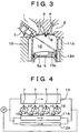
- Fig. 3 schematically shows a longitudinal section of a direct-fuel-injection-type spark-ignition internal combustion engine in accordance with a second embodiment of the invention.
- Fig. 4 is a system diagram of coolant passages of the second embodiment. The description of the second embodiment will be limited to what is different from the first embodiment.
- the upper coolant passage and the lower coolant passage are integrated with each other on the fuel injection valve side, whereby a fuel-injection-valve-side coolant passage 13 is formed.
- the lower coolant passage 12A is smaller in cross-section than the upper coolant passage 11A.
- the second embodiment can solve the problems of deterioration of fuel consumption rate and dilution of engine oil.
- Fig. 5 schematically shows a longitudinal section of a direct-fuel-injection-type spark-ignition internal combustion engine in accordance with a third embodiment of the invention.
- Fig. 6 is a system diagram of coolant passages of the third embodiment. The description of the third embodiment will be limited to what is different from the second embodiment. In this embodiment, there is no lower coolant passage on the side opposed to the nozzle hole of the fuel injection valve.
- the third embodiment can solve the problems of deterioration of fuel consumption rate and dilution of engine oil more reliably than the second embodiment.
- Fig. 7 schematically shows a longitudinal section of a direct-fuel-injection-type spark-ignition internal combustion engine in accordance with a fourth embodiment of the invention.
- Fig. 8 is a system diagram of coolant passages of the fourth embodiment. The description of the fourth embodiment will be limited to what is different from the third embodiment.
- an adiabatic air layer 14 is formed in the neighborhood of the lower section of the cylinder bore 10.
- a cylinder block in which the cylinder bore 10 is formed is made of metal.
- the impingement portion 10a opposed to the nozzle hole of the fuel injection valve in the cylinder bore 10 can be maintained at a higher temperature. Thereby it becomes possible to more effectively gasify fuel that is injected during the latter half of an intake stroke and that initially adheres to the portion 10a opposed to the nozzle of the fuel injection valve.
- the fourth embodiment can solve the problems of deterioration of fuel consumption rate and dilution of engine oil more reliably than the third embodiment.
- the air layer is formed as an adiabatic layer in this embodiment, it goes without saying that other gaseous layers, liquid layers or solid layers with a lower heat transfer rate than the metal forming the cylinder block may be formed.
- Fig. 9 schematically shows a longitudinal section of a direct-fuel-injection-type spark-ignition internal combustion engine in accordance with a fifth embodiment of the invention.
- Fig. 10 is a system diagram of coolant passages of the fifth embodiment. The description of the fifth embodiment will be limited to what is different from the fourth embodiment.
- an exhaust passage 15 is formed and functions as heating means in the neighborhood of the lower section of the cylinder bore 10, instead of the adiabatic layer. As indicated by a hollow arrow in Fig. 10, exhaust gas flows through the exhaust passage 15.
- the upper section of the cylinder bore 10 is exposed to combustion gas at an extremely high temperature in the initial stage of a combustion stroke and thus reaches an extremely high temperature.
- the lower section of the cylinder bore 10 is only exposed to combustion gas in the latter half of a combustion stroke and thus does not reach a very high temperature. Thereafter, when an intake stroke begins after an exhaust stroke, intake air introduced into the cylinder also cools the cylinder bore 10. In the latter half of an intake stroke, the lower section of the cylinder bore 10 is lower in temperature than exhaust gas that has just been discharged from the cylinder.
- the impingement portion 10a opposed to the nozzle hole of the fuel injection valve in the lower section of the cylinder bore 10 can be heated by exhaust gas that has just been discharged from the cylinder and that is at a high temperature.
- the impingement portion 10a opposed to the nozzle hole of the fuel injection valve further rises in temperature and becomes capable of gasifying adherent fuel almost instantaneously.
- the fifth embodiment can more reliably solve the problems of deterioration of fuel consumption rate and dilution of engine oil.
- the exhaust passage 15 may be designed as part of a main exhaust passage of the engine through which exhaust gas flows constantly. However, in this embodiment, the exhaust passage 15 is designed as a branch exhaust passage which branches off from a main exhaust passage 16 through a control valve 17, as can be seen from Fig. 10. At the time of stratified charge combustion, which does not require heating of the impingement portion 10a opposed to the nozzle hole of the fuel injection valve in the cylinder bore 10, the control valve 17 is closed so that exhaust gas does not flow through the branch exhaust passage 15. Thus, at the time of stratified charge combustion, the impingement portion 10a opposed to the nozzle hole of the fuel injection valve in the cylinder bore 10 is maintained at almost the same temperature as in the fourth embodiment wherein the adiabatic layer is formed.
- the upper section of the cylinder bore 10 is exposed to combustion gas at an extremely high temperature in the initial stage of a combustion stroke and thus reaches an extremely high temperature.
- the engine cooling system of the first through fifth embodiments ensures high cooling capacity for the upper section of the cylinder bore 10 so as to prevent overheating.
- the lower section of the cylinder bore 10 is exposed to combustion gas only in the latter half of a combustion stroke and thus does not reach a very high temperature.
- the interior of the cylinder be at a low temperature.
- high cooling capacity for the lower section of the cylinder bore 10 on the fuel injection valve side is ensured. Therefore, regardless of whether stratified charge combustion or homogeneous combustion is carried out, the enhancement of intake air filling efficiency can be effectively achieved.
- the cooling capacity on the fuel injection valve side does not coincide with the cooling capacity on the side opposed to the fuel injection valve.
- phenomena such as swaying defacement of a piston ring may be caused.
- the cooling capacity for the lower section of the cylinder bore 10 on the fuel injection valve side needs to coincide with the cooling capacity for the lower section of the cylinder bore 10 on the side opposed to the fuel injection valve.
- the coolant passage may be dispensed with in the third embodiment, an adiabatic layer may be formed in the fourth embodiment, and an exhaust passage may be formed in the fifth embodiment.
- Fig. 11 schematically shows a longitudinal section of a direct-fuel-injection-type spark-ignition internal combustion engine in accordance with a sixth embodiment of the invention.
- Fig. 12 is a system diagram of coolant passages of the sixth embodiment.
- the upper coolant passages 11A, 11B and lower coolant passages 18A, 18B are provided as coolant passages for cooling the cylinder bores 10.
- the upper coolant passages 11A, 11B and the lower coolant passages 18A, 18B are substantially equal in cross-section.
- coolant discharged from the coolant pump P is substantially evenly distributed to the upper coolant passages 11A, 11B and the lower coolant passages 18A, 18B through a control valve 19. Thereafter, the coolant is respectively distributed to the fuel injection valve side and the side opposed to the fuel injection valve.
- a substantially uniform amount of coolant respectively flows through the coolant passages 11A, 11B, 18A and 18B.
- the upper and lower sections of the cylinder bore 10 are effectively cooled. That is, the entire cylinder bore 10 is effectively cooled and the interior of the cylinder falls in temperature. As a result, it is possible to realize stratified charge combustion with high intake air filling efficiency.
- the opening degree of the control valve 19 is reduced so that the amount of coolant flowing through the lower coolant passages 18A, 18B is reduced.
- the cooling capacity for the lower section of-the cylinder bore 10 is made lower than the cooling capacity for the upper section of the cylinder bore 10.
- the lower section of the cylinder bore 10 is not sufficiently cooled and thus reaches a high temperature.
- Fig. 13 schematically shows a longitudinal section of a direct-fuel-injection-type spark-ignition internal combustion engine in accordance with a seventh embodiment of the invention.
- Fig. 14 is a system diagram of coolant passages of the seventh embodiment.
- a coolant passage 20A on the side opposed to the fuel injection valve and a coolant passage 20B on the fuel injection valve side are provided as coolant passages for cooling the cylinder bores 10.
- the coolant passages 20A, 20B are substantially equal in cross-section.
- coolant discharged from the coolant pump P is substantially evenly distributed to the coolant passage 20B on the fuel injection valve side and the coolant passage 20A on the side opposed to the fuel injection valve through a control valve 21.
- a substantially uniform amount of coolant respectively flows through the coolant passages 20A, 20B.
- the cylinder bore 10 is effectively cooled both on the side opposed to the fuel injection valve and on the fuel injection valve side. That is, the entire cylinder bore 10 is effectively cooled and the interior of the cylinder falls in temperature. As a result, it is possible to realize stratified charge combustion with high intake air filling efficiency.
- the opening degree of the control valve 21 is reduced so that the amount of coolant flowing through the coolant passage 20A on the side opposed to the fuel injection valve is reduced.
- the cooling capacity for the cylinder bore 10 on the side opposed to the fuel injection valve is made lower than the cooling capacity for the cylinder bore 10 on the fuel injection valve side.
- the cylinder bore 10 on the side opposed to the fuel injection valve is not sufficiently cooled and thus reaches a high temperature.
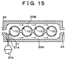
- Fig. 15 is a cross-sectional view of a specific structure of a cylinder block in accordance with this embodiment.
- the coolant passage 20A on the side opposed to the fuel injection valve and the coolant passage 20B on the fuel injection valve side are integrated with each other to define a space surrounding cylinder bores 10 which are aligned with one another.
- an inlet 22 for coolant is formed at one end, and an outlet 23 for coolant is formed at the other end.
- a longitudinal valve body 21 designed as a control valve which can close the space on the side opposed to the fuel injection valve is disposed in the neighborhood of the inlet 22.
- An operating shaft 21a of the longitudinal valve body 21 penetrates the cylinder block outwards in a watertight manner and is connected to a diaphragm 21b, which functions as an actuator.
- the longitudinal valve body 21 does not close the entirety or the lower section of the coolant passage 20A on the side opposed to the fuel injection valve, if the coolant passage 20A is reduced in cross-section through the longitudinal valve body 21, the cooling capacity for the entirety or the lower section of the cylinder bore 10 on the side opposed to the fuel injection valve decreases. As a result, it is possible to promote gasification of adherent fuel.
- a partition wall may be provided between the upper section and the lower section of the cylinder bore 10 so that coolant constantly flows on the fuel injection valve side and the side opposed to the fuel injection valve in the upper section and that the upper section is sufficiently cooled.
- the lower section may be exclusively constructed as shown in Fig. 15 so that the coolant passage on the side opposed to the fuel injection valve is closed or reduced in cross-section by the longitudinal valve body at the time of homogeneous combustion. Because this construction not only achieves effective gasification of adherent fuel at the time of homogeneous combustion but also cools the upper sections of the respective cylinder bores 10 constantly and sufficiently, the occurrence of overheating can be more reliably prevented.
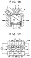
- Fig. 16 schematically shows a longitudinal section of a direct-fuel-injection-type spark-ignition internal combustion engine in accordance with an eighth embodiment of the invention.
- Fig. 17 is a system diagram of coolant passages of the eighth embodiment.
- a coolant passage 24A on the side opposed to the fuel injection valve and a coolant passage 24B on the fuel injection valve side are provided as coolant passages for cooling the cylinder bores 10.
- the coolant passages 24A, 24B are substantially equal in cross-section.
- the coolant passage 24A on the side opposed to the fuel injection valve and the coolant passage 24B on the fuel injection valve side communicate with each other through communication passages 25, each of which extends between two adjacent ones of the cylinder bores.
- a control valve 26 which is closed during a period of homogeneous combustion is disposed in each communication passage 25.
- coolant discharged from the coolant pump P first flows through the coolant passage 24B on the fuel injection valve side and then flows through the coolant passage 24A on the side opposed to the fuel injection valve.
- coolant which has flowed through the coolant passage 24B on the fuel injection valve side which has cooled the respective cylinder bores on the fuel injection valve side and which has reached a high temperature flows through the coolant passage 24A on the side opposed to the fuel injection valve.
- the respective cylinder bores 10 on the side opposed to the fuel injection valve are not sufficiently cooled, and adherent fuel can be effectively gasified.
- the control valves 26 are opened so that coolant flows from the coolant passage 24B on the fuel injection valve side to the coolant passage 24A on the side opposed to the fuel injection valve through the communication passages 25 as indicated by dotted lines. If one of the cylinder bores 10 is located close to the coolant pump P, coolant which has only cooled a small number of cylinder bores 10 cools that cylinder bore 10 on the side opposed to the fuel injection valve. Thus, sufficient cooling capacity is ensured, and it is possible to realize stratified charge combustion with high intake air filling efficiency.
- the temperature of coolant for cooling the side opposed to the fuel injection valve remains substantially unchanged regardless of whether homogeneous combustion or stratified charge combustion is carried out.
- coolant which has cooled all the cylinder bores 10 on the fuel injection valve side which has cooled the other cylinder bores 10 on the side opposed to the fuel injection valve and which has reached a considerably high temperature flows in the neighborhood of the side opposed to the fuel injection valve.
- insufficient cooling enables effective gasification of adherent fuel at the time of homogeneous combustion.
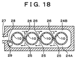
- Fig. 18 is a cross-sectional view of a specific structure of a cylinder block in accordance with this embodiment.
- the coolant passage 24A on the side opposed to the fuel injection valve and the coolant passage 24B on the fuel injection valve side are integrated with each other to define a space surrounding cylinder bores 10 which are aligned with one another.
- An inlet 27 for coolant is formed at one end, of the coolant passage 24B on the fuel injection valve side.
- a partition wall 28, which separates the coolant passage 24B on the fuel injection valve side from the coolant passage 24A on the side opposed to the fuel injection valve, is provided in the neighborhood of the inlet 27.
- An outlet 29 for coolant is formed in the neighborhood of the partition wall 28 in the coolant passage 24A on the side opposed to the fuel injection valve.
- the coolant passage 24B on the fuel injection valve side and the coolant passage 24A on the side opposed to the fuel injection valve communicate with each other through the communication passages 25.
- a butterfly-valve-type control valve 26 is disposed in each of the communication passages 25.
- a step motor or the like can be used as an actuator for the control valve.
- the overall structure can be simplified.
- a partition wall is provided between the upper section and the lower section of each of the cylinder bores 10.
- the coolant passage on the side opposed to the fuel injection valve and the coolant passage on the fuel injection valve side constantly communicate with each other through the communication passages extending between two adjacent ones of the cylinder bores so that the upper sections of the cylinder bores 10 are sufficiently cooled.
- the lower section is exclusively constructed as shown in Fig. 18, and the control valves 26 are closed at the time of homogeneous combustion. This construction not only achieves effective gasification of adherent fuel at the time of homogeneous combustion but also cools the upper sections of the cylinder bores 10 sufficiently and constantly. Therefore, the occurrence of overheating can be prevented more reliably.
- the overall cooling capacity for the fuel injection valve side of the cylinder bore 10 is reduced at the time of homogeneous combustion.
- the nozzle hole of the fuel injection valve that is used be directed towards the lower section of the cylinder bore 10.
- the nozzle hole of the fuel injection valve may be directed towards the upper section of the cylinder bore so that combustible mixture is directly formed in the neighborhood of the ignition plug at the time of stratified charge combustion without using the cavity in the top face of the piston.
- cooling fins may be provided as engine cooling means. Also, the cooling fins may be varied in size or number to create a difference in cooling capacity as described above.
- a direct-fuel-injection-type spark-ignition internal combustion engine has a fuel injection valve (7) which directly injects fuel into a cylinder and switches its combustion mode in accordance with an operating state of the engine between stratified charge combustion in which fuel injection occurs during the latter half of a compression stroke and homogeneous combustion in which fuel injection occurs during an intake stroke.
- a nozzle hole of the fuel injection valve (7) directs fuel toward an impingement portion of the cylinder bore (10) located opposed to the nozzle hole in a lower section of the cylinder bore (10) so that fuel can be injected into a cavity (5a) formed in a top face of a piston (5) from an upper section of the cylinder bore (10) during the latter half of a compression stroke.
- a cooler (12A) located at least in the neighborhood of the impingement portion in the lower section of the cylinder bore has a lower cooling capacity than a cooler (11A) located in the neighborhood of the upper section of the cylinder bore (10). Because of this construction, even if fuel injected during the latter half of an intake stroke collides with the cylinder bore (10) and initially adheres thereto, the adherent fuel can be effectively gasified.
Landscapes
- Engineering & Computer Science (AREA)
- Chemical & Material Sciences (AREA)
- Combustion & Propulsion (AREA)
- Mechanical Engineering (AREA)
- General Engineering & Computer Science (AREA)
- Combustion Methods Of Internal-Combustion Engines (AREA)
- Fuel-Injection Apparatus (AREA)
- Exhaust Silencers (AREA)
- Cylinder Crankcases Of Internal Combustion Engines (AREA)
- Electrical Control Of Air Or Fuel Supplied To Internal-Combustion Engine (AREA)
Abstract
Description
Claims (12)
- A direct-fuel-injection-type spark-ignition internal combustion engine which switches its combustion mode in accordance with an operating state of the engine between stratified charge combustion in which fuel is injected during a latter half of a compression stroke and homogeneous combustion in which fuel is injected during an intake stroke, characterized by comprising:a cylinder bore (10) into which the fuel is injected to cause the stratified charge combustion or the homogeneous combustion;a fuel injection valve (7) located in an upper section of the cylinder bore (10), and which directs fuel toward an impingement portion (10a) of the cylinder bore (10) located opposed to the fuel injection valve (7) in a lower section of the cylinder bore (10); anda cooler (11A, 11B, 12A, 12B) which cools the cylinder bore (10) so as to suppress a fall in temperature of at least one area of the cylinder adjacent to the impingement portion (10a) in comparison with a fall in temperature of the other area of the cylinder bore (10) than the at least one area adjacent to the impingement portion (10a).
- The direct-fuel-injection-type spark-ignition internal combustion engine according to claim 1, characterized in that :the cooler has a first cooling portion (11A, 11B) and a second cooling portion (12A, 12B),the first cooling portion (11A, 11B) cools an area close to the upper section of the cylinder bore (10); andthe second cooling portion (12A, 12B) cools the at least one area adjacent to the impingement portion (10a) in the lower section of the cylinder bore (10) with a lower cooling capacity than a cooling capacity of the first cooling portion (11A, 11B).
- The direct-fuel-injection-type spark-ignition internal combustion engine according to claim 2, characterized in that:the cooler includes coolant passages; andthe coolant passage (12A, 12B) corresponding to the second cooling portion is smaller in cross-section than the coolant passage (11A, 11B) corresponding to the first cooling portion.
- A direct-fuel-injection-type spark-ignition internal combustion engine according to claim 1, characterized in that;the cooler (11A) is disposed only in an area adjacent to the upper section of the cylinder bore (10) and which cools the cylinder bore (10).
- The direct-fuel-injection-type spark-ignition internal combustion engine according to claim 4, characterized by further comprising:a heat insulator (14) located at least in an area adjacent to the impingement portion (10a) in the lower section of the cylinder bore (10).
- The direct-fuel-injection-type spark-ignition internal combustion engine according to claim 4, characterized by further comprising:a heater (15) located at least in an area adjacent to the impingement portion (10a) in the lower section of the cylinder bore (10).
- The direct-fuel-injection-type spark-ignition internal combustion engine according to claim 6, characterized in that:the heater includes an exhaust passage.
- The direct-fuel-injection-type spark-ignition internal combustion- engine according to claim 7, wherein the exhaust passage is a branch exhaust passage which branches off from a main exhaust passage, characterized by further comprising:a control valve (17) disposed in the branch exhaust passage and which reduces an amount of exhaust gas flowing through the branch exhaust passage by reducing an opening degree of the control valve (17) during the stratified charge combustion in comparison with an opening degree of the control valve (17) during the homogeneous combustion.
- A direct-fuel-injection-type spark-ignition internal combustion engine according to claim 1, characterized in that:the cooler includes a coolant passage which has a first passage (18A, 18B) and a second passage (11A, 11B) and which cools the cylinder bore (10), wherein the first passage (18A, 18B) is located at least in an area adjacent to the impingement portion (10a) in the lower section of the cylinder bore (10) and wherein the second passage (11A, 11B) is independent of the first passage (18A, 18B) and is located at least in an area adjacent to an upper section of the cylinder bore (10); anda control valve (19) disposed in the first passage (18A, 18B) and which reduces an amount of coolant flowing through the first passage (18A, 18B) by reducing an opening degree of the control valve (19) during the homogeneous combustion in comparison with an opening degree of the control valve (19) during the stratified charge combustion.
- A direct-fuel-injection-type spark-ignition internal combustion engine according to claim 1, characterized in that:a cylinder bore (10) has a first side and a second side opposite from the first side;a fuel injection valve (7) located at the first side and which directly injects fuel into the second side of the cylinder bore (10) which contains the impingement portion (10a);the cooler includes a coolant passage which has a first passage (20A) and a second passage (20B) and which cools the cylinder bore (10), wherein the first passage (20A) is located in an area adjacent to the second side of the cylinder bore (10) and wherein the second passage (20B) is independent of the first passage (20A) and is located in an area adjacent to the first side of the cylinder bore (10); anda control valve (21) disposed in the first passage (20A) and which reduces an amount of coolant flowing through the first passage (20A) by reducing an opening degree of the control valve (7) during the homogeneous combustion in comparison with an opening degree of the control valve (7) during the stratified charge combustion.
- A direct-fuel-injection-type spark-ignition internal combustion engine according to claim 1, characterized in that:the internal combustion engine includes a plurality of the cylinder bores (10) having a first side and a second side opposite from the first, each cylinder bore (10) has a fuel injection valve (7) located at the first side and which directly injects fuel into the second side of its respective cylinder bore (10);the cooler includes a coolant passage which has a first passage (24A) and a second passage (24B) and which cools the plurality of cylinder bores (10), wherein the first passage (24A) extends in an area adjacent to the second side of the cylinder bores (10) and wherein the second passage (24B) extends in an area adjacent to the first side of the cylinder bores (10);a coolant inlet portion (27) provided at a first end of the second passage (24B);a coolant outlet portion (29) provided at a first end of the first passage (24A);a communication passage (25) which extends between two of the cylinder bores (10) and through which the first passage communicates with the second passage, wherein a second end of the first passage (24A) communicates with a second end of the second passage (24B); anda control valve (26) disposed in the communication passage (25) and which reduces an amount of coolant flowing through the communication passage (25) by reducing an opening degree of the control valve (26) during the homogeneous combustion in comparison with an opening degree of the control valve (26) during the stratified charge combustion.
- The direct-fuel-injection-type spark-ignition internal combustion engine according to claim 11, characterized in that:the fuel injection valves (7) direct the fuel toward a lower section of the cylinder bores (10) so that the fuel can be injected into a cavity formed in a top face of a piston from an upper section of the cylinder bores during the latter half of the compression stroke;the first passage (24A) and the second passage (24B) extend between the lower sections of the cylinder bores (10); andthe coolant passage further comprises:a third passage which extends in an area adjacent to the second side in the upper sections of the cylinder bores (10);a fourth passage which extends in an area adjacent to the first side in the upper sections of the cylinder bores (10);a coolant inlet portion provided at a first end of one of the third and fourth passages;a coolant outlet portion provided at a first end of the other of the third and fourth passages; anda communication passage which extends between the cylinder bores and through which the third passage communicates with the fourth passage.
Applications Claiming Priority (2)
| Application Number | Priority Date | Filing Date | Title |
|---|---|---|---|
| JP22281599A JP3800875B2 (en) | 1999-08-05 | 1999-08-05 | In-cylinder injection spark ignition internal combustion engine |
| JP22281599 | 1999-08-05 |
Publications (3)
| Publication Number | Publication Date |
|---|---|
| EP1074723A2 true EP1074723A2 (en) | 2001-02-07 |
| EP1074723A3 EP1074723A3 (en) | 2002-03-20 |
| EP1074723B1 EP1074723B1 (en) | 2006-11-15 |
Family
ID=16788354
Family Applications (1)
| Application Number | Title | Priority Date | Filing Date |
|---|---|---|---|
| EP00116802A Expired - Lifetime EP1074723B1 (en) | 1999-08-05 | 2000-08-03 | Direct-fuel-injection-type spark-ignition internal combustion engine and method of controlling the internal combustion engine |
Country Status (4)
| Country | Link |
|---|---|
| US (1) | US6349697B1 (en) |
| EP (1) | EP1074723B1 (en) |
| JP (1) | JP3800875B2 (en) |
| DE (1) | DE60031810T2 (en) |
Cited By (1)
| Publication number | Priority date | Publication date | Assignee | Title |
|---|---|---|---|---|
| WO2009007143A1 (en) * | 2007-07-06 | 2009-01-15 | Brp-Rotax Gmbh & Co. Kg | Internal combustion engine cooling system |
Families Citing this family (12)
| Publication number | Priority date | Publication date | Assignee | Title |
|---|---|---|---|---|
| US6892693B2 (en) * | 2003-02-12 | 2005-05-17 | Bombardier Recreational Products, Inc. | Piston for spark-ignited direct fuel injection engine |
| US7021250B2 (en) * | 2003-06-11 | 2006-04-04 | Daimlerchrysler Corporation | Precision cooling system |
| US6945219B2 (en) * | 2004-02-09 | 2005-09-20 | Bombardier Recreational Products Inc. | Dual zone combustion chamber |
| JP5104195B2 (en) * | 2007-10-19 | 2012-12-19 | トヨタ自動車株式会社 | Spark ignition internal combustion engine |
| JP5359284B2 (en) * | 2009-01-07 | 2013-12-04 | トヨタ自動車株式会社 | Engine cooling system |
| MX2013011860A (en) * | 2011-04-12 | 2014-01-31 | Nissan Motor | Internal combustion engine. |
| JP5605711B2 (en) * | 2011-05-19 | 2014-10-15 | 三菱自動車工業株式会社 | In-cylinder direct injection spark ignition internal combustion engine |
| AT513053B1 (en) * | 2012-06-26 | 2014-03-15 | Avl List Gmbh | Internal combustion engine, in particular large diesel engine |
| WO2016203707A1 (en) * | 2015-06-15 | 2016-12-22 | 本田技研工業株式会社 | Cooling structure of internal-combustion engine |
| JP6623665B2 (en) * | 2015-10-14 | 2019-12-25 | 三菱自動車工業株式会社 | In-cylinder direct injection internal combustion engine |
| JP6709255B2 (en) * | 2018-07-27 | 2020-06-10 | 本田技研工業株式会社 | Internal combustion engine cooling structure |
| US10876462B1 (en) * | 2019-07-18 | 2020-12-29 | Ford Global Technologies, Llc | Coolant jacket insert |
Family Cites Families (9)
| Publication number | Priority date | Publication date | Assignee | Title |
|---|---|---|---|---|
| US4346676A (en) * | 1979-08-06 | 1982-08-31 | Brunswick Corporation | Two-cycle V-engine with integrally cast exhaust manifold |
| JP2724608B2 (en) * | 1989-02-17 | 1998-03-09 | 三信工業株式会社 | Water cooling system for V-type two-stroke internal combustion engine for ships |
| DE4206920C1 (en) * | 1992-03-05 | 1992-12-24 | Mercedes-Benz Aktiengesellschaft, 7000 Stuttgart, De | Cooling circuit for vehicle IC engine - has connecting passage between opposing pairs of cylinders, and cooling fluid chamber |
| JPH07109953A (en) * | 1993-10-12 | 1995-04-25 | Yamaha Motor Co Ltd | In-cylinder fuel injection type two-cycle engine piston |
| US5542381A (en) * | 1994-02-07 | 1996-08-06 | Nissan Motor Co., Ltd. | Cylinder block for liquid-cooled engine |
| JPH07259555A (en) * | 1994-03-18 | 1995-10-09 | Toyota Motor Corp | Cooling system of internal combustion engine |
| JP3921732B2 (en) | 1997-04-28 | 2007-05-30 | マツダ株式会社 | In-cylinder injection type spark ignition engine |
| JP3553765B2 (en) * | 1997-06-27 | 2004-08-11 | 株式会社日本自動車部品総合研究所 | In-cylinder direct injection internal combustion engine |
| JP3758003B2 (en) | 1997-08-11 | 2006-03-22 | 三菱自動車工業株式会社 | In-cylinder injection type spark ignition type internal combustion engine control device |
-
1999
- 1999-08-05 JP JP22281599A patent/JP3800875B2/en not_active Expired - Fee Related
-
2000
- 2000-07-17 US US09/617,271 patent/US6349697B1/en not_active Expired - Fee Related
- 2000-08-03 DE DE60031810T patent/DE60031810T2/en not_active Expired - Fee Related
- 2000-08-03 EP EP00116802A patent/EP1074723B1/en not_active Expired - Lifetime
Non-Patent Citations (1)
| Title |
|---|
| None |
Cited By (3)
| Publication number | Priority date | Publication date | Assignee | Title |
|---|---|---|---|---|
| WO2009007143A1 (en) * | 2007-07-06 | 2009-01-15 | Brp-Rotax Gmbh & Co. Kg | Internal combustion engine cooling system |
| US7845316B2 (en) | 2007-07-06 | 2010-12-07 | Brp-Powertrain Gmbh & Co Kg | Internal combustion engine cooling system |
| CN101688464B (en) * | 2007-07-06 | 2012-05-23 | Brp罗泰克斯有限两合公司 | Internal combustion engine cooling system |
Also Published As
| Publication number | Publication date |
|---|---|
| EP1074723B1 (en) | 2006-11-15 |
| DE60031810T2 (en) | 2007-09-13 |
| JP3800875B2 (en) | 2006-07-26 |
| US6349697B1 (en) | 2002-02-26 |
| EP1074723A3 (en) | 2002-03-20 |
| DE60031810D1 (en) | 2006-12-28 |
| JP2001050101A (en) | 2001-02-23 |
Similar Documents
| Publication | Publication Date | Title |
|---|---|---|
| US6349697B1 (en) | Direct-fuel-injection-type spark-ignition internal combustion engine and method of controlling the internal combustion engine | |
| US6691649B2 (en) | Fuel injection system for a two-stroke engine | |
| US7055491B2 (en) | Piston-cylinder combination for a combustion engine | |
| US7025036B2 (en) | Valve controlled divided chamber internal combustion engine | |
| JP2009062836A (en) | Cylinder head of internal combustion engine | |
| JP2000104551A (en) | Direct injection gasoline engine | |
| CN107620661A (en) | The method of explosive motor and the explosive motor for operating the type | |
| CN213331297U (en) | Cylinder head assembly with dual injector port injection and integrated exhaust structure | |
| EP3889401A1 (en) | Valve, combustion-chamber structure, engine and vehicle | |
| CN114962049A (en) | Internal combustion engine | |
| KR100921412B1 (en) | Cylinder head of reciprocating internal combustion engine with cooling passage system | |
| US11078866B1 (en) | Combustion-chamber structure of engine | |
| JP2001050106A (en) | Cylinder head structure of internal combustion engine | |
| JP2004100545A (en) | Oil jet for cooling piston of internal combustion engine | |
| EP4257819B1 (en) | Internal combustion engine | |
| CN115135862B (en) | Cooling systems for internal combustion engines | |
| KR100231339B1 (en) | Gasoline engine of car | |
| CN118548157A (en) | A high-power dual-fuel engine cylinder head | |
| JP2007187107A (en) | Internal combustion engine | |
| JP2521329Y2 (en) | Fuel injection nozzle for direct injection diesel engine | |
| JP2024092825A (en) | engine | |
| JPS59145344A (en) | Piston fitted with combustion chamber | |
| JP5278603B2 (en) | engine | |
| KR200171007Y1 (en) | Cylinder head structure for flame ignition engine | |
| CN121676124A (en) | Fuel injection method and fuel injection system for methanol compression ignition engine |
Legal Events
| Date | Code | Title | Description |
|---|---|---|---|
| PUAI | Public reference made under article 153(3) epc to a published international application that has entered the european phase |
Free format text: ORIGINAL CODE: 0009012 |
|
| 17P | Request for examination filed |
Effective date: 20000803 |
|
| AK | Designated contracting states |
Kind code of ref document: A2 Designated state(s): AT BE CH CY DE DK ES FI FR GB GR IE IT LI LU MC NL PT SE Kind code of ref document: A2 Designated state(s): DE FR GB IT |
|
| AX | Request for extension of the european patent |
Free format text: AL;LT;LV;MK;RO;SI |
|
| PUAL | Search report despatched |
Free format text: ORIGINAL CODE: 0009013 |
|
| AK | Designated contracting states |
Kind code of ref document: A3 Designated state(s): AT BE CH CY DE DK ES FI FR GB GR IE IT LI LU MC NL PT SE |
|
| AX | Request for extension of the european patent |
Free format text: AL;LT;LV;MK;RO;SI |
|
| AKX | Designation fees paid |
Free format text: DE FR GB IT |
|
| 17Q | First examination report despatched |
Effective date: 20041129 |
|
| GRAP | Despatch of communication of intention to grant a patent |
Free format text: ORIGINAL CODE: EPIDOSNIGR1 |
|
| GRAS | Grant fee paid |
Free format text: ORIGINAL CODE: EPIDOSNIGR3 |
|
| GRAA | (expected) grant |
Free format text: ORIGINAL CODE: 0009210 |
|
| AK | Designated contracting states |
Kind code of ref document: B1 Designated state(s): DE FR GB IT |
|
| REG | Reference to a national code |
Ref country code: GB Ref legal event code: FG4D |
|
| REF | Corresponds to: |
Ref document number: 60031810 Country of ref document: DE Date of ref document: 20061228 Kind code of ref document: P |
|
| ET | Fr: translation filed | ||
| PGFP | Annual fee paid to national office [announced via postgrant information from national office to epo] |
Ref country code: DE Payment date: 20070726 Year of fee payment: 8 |
|
| PLBE | No opposition filed within time limit |
Free format text: ORIGINAL CODE: 0009261 |
|
| STAA | Information on the status of an ep patent application or granted ep patent |
Free format text: STATUS: NO OPPOSITION FILED WITHIN TIME LIMIT |
|
| 26N | No opposition filed |
Effective date: 20070817 |
|
| PGFP | Annual fee paid to national office [announced via postgrant information from national office to epo] |
Ref country code: GB Payment date: 20070801 Year of fee payment: 8 |
|
| PGFP | Annual fee paid to national office [announced via postgrant information from national office to epo] |
Ref country code: IT Payment date: 20070830 Year of fee payment: 8 |
|
| PGFP | Annual fee paid to national office [announced via postgrant information from national office to epo] |
Ref country code: FR Payment date: 20070808 Year of fee payment: 8 |
|
| GBPC | Gb: european patent ceased through non-payment of renewal fee |
Effective date: 20080803 |
|
| REG | Reference to a national code |
Ref country code: FR Ref legal event code: ST Effective date: 20090430 |
|
| PG25 | Lapsed in a contracting state [announced via postgrant information from national office to epo] |
Ref country code: IT Free format text: LAPSE BECAUSE OF NON-PAYMENT OF DUE FEES Effective date: 20080803 Ref country code: FR Free format text: LAPSE BECAUSE OF NON-PAYMENT OF DUE FEES Effective date: 20080901 Ref country code: DE Free format text: LAPSE BECAUSE OF NON-PAYMENT OF DUE FEES Effective date: 20090303 |
|
| PG25 | Lapsed in a contracting state [announced via postgrant information from national office to epo] |
Ref country code: GB Free format text: LAPSE BECAUSE OF NON-PAYMENT OF DUE FEES Effective date: 20080803 |