EP1074712A2 - Electronic throttle control system - Google Patents
Electronic throttle control system Download PDFInfo
- Publication number
- EP1074712A2 EP1074712A2 EP00115040A EP00115040A EP1074712A2 EP 1074712 A2 EP1074712 A2 EP 1074712A2 EP 00115040 A EP00115040 A EP 00115040A EP 00115040 A EP00115040 A EP 00115040A EP 1074712 A2 EP1074712 A2 EP 1074712A2
- Authority
- EP
- European Patent Office
- Prior art keywords
- throttle
- engine
- electronically controlled
- control system
- engine control
- Prior art date
- Legal status (The legal status is an assumption and is not a legal conclusion. Google has not performed a legal analysis and makes no representation as to the accuracy of the status listed.)
- Granted
Links
Images


Classifications
-
- F—MECHANICAL ENGINEERING; LIGHTING; HEATING; WEAPONS; BLASTING
- F02—COMBUSTION ENGINES; HOT-GAS OR COMBUSTION-PRODUCT ENGINE PLANTS
- F02D—CONTROLLING COMBUSTION ENGINES
- F02D11/00—Arrangements for, or adaptations to, non-automatic engine control initiation means, e.g. operator initiated
- F02D11/06—Arrangements for, or adaptations to, non-automatic engine control initiation means, e.g. operator initiated characterised by non-mechanical control linkages, e.g. fluid control linkages or by control linkages with power drive or assistance
- F02D11/10—Arrangements for, or adaptations to, non-automatic engine control initiation means, e.g. operator initiated characterised by non-mechanical control linkages, e.g. fluid control linkages or by control linkages with power drive or assistance of the electric type
-
- F—MECHANICAL ENGINEERING; LIGHTING; HEATING; WEAPONS; BLASTING
- F02—COMBUSTION ENGINES; HOT-GAS OR COMBUSTION-PRODUCT ENGINE PLANTS
- F02D—CONTROLLING COMBUSTION ENGINES
- F02D11/00—Arrangements for, or adaptations to, non-automatic engine control initiation means, e.g. operator initiated
- F02D11/06—Arrangements for, or adaptations to, non-automatic engine control initiation means, e.g. operator initiated characterised by non-mechanical control linkages, e.g. fluid control linkages or by control linkages with power drive or assistance
- F02D11/10—Arrangements for, or adaptations to, non-automatic engine control initiation means, e.g. operator initiated characterised by non-mechanical control linkages, e.g. fluid control linkages or by control linkages with power drive or assistance of the electric type
- F02D11/106—Detection of demand or actuation
-
- F—MECHANICAL ENGINEERING; LIGHTING; HEATING; WEAPONS; BLASTING
- F02—COMBUSTION ENGINES; HOT-GAS OR COMBUSTION-PRODUCT ENGINE PLANTS
- F02D—CONTROLLING COMBUSTION ENGINES
- F02D41/00—Electrical control of supply of combustible mixture or its constituents
- F02D41/22—Safety or indicating devices for abnormal conditions
- F02D41/221—Safety or indicating devices for abnormal conditions relating to the failure of actuators or electrically driven elements
-
- F—MECHANICAL ENGINEERING; LIGHTING; HEATING; WEAPONS; BLASTING
- F02—COMBUSTION ENGINES; HOT-GAS OR COMBUSTION-PRODUCT ENGINE PLANTS
- F02D—CONTROLLING COMBUSTION ENGINES
- F02D41/00—Electrical control of supply of combustible mixture or its constituents
- F02D41/24—Electrical control of supply of combustible mixture or its constituents characterised by the use of digital means
- F02D41/26—Electrical control of supply of combustible mixture or its constituents characterised by the use of digital means using computer, e.g. microprocessor
- F02D41/266—Electrical control of supply of combustible mixture or its constituents characterised by the use of digital means using computer, e.g. microprocessor the computer being backed-up or assisted by another circuit, e.g. analogue
-
- F—MECHANICAL ENGINEERING; LIGHTING; HEATING; WEAPONS; BLASTING
- F02—COMBUSTION ENGINES; HOT-GAS OR COMBUSTION-PRODUCT ENGINE PLANTS
- F02D—CONTROLLING COMBUSTION ENGINES
- F02D41/00—Electrical control of supply of combustible mixture or its constituents
- F02D41/22—Safety or indicating devices for abnormal conditions
- F02D2041/227—Limping Home, i.e. taking specific engine control measures at abnormal conditions
-
- F—MECHANICAL ENGINEERING; LIGHTING; HEATING; WEAPONS; BLASTING
- F02—COMBUSTION ENGINES; HOT-GAS OR COMBUSTION-PRODUCT ENGINE PLANTS
- F02D—CONTROLLING COMBUSTION ENGINES
- F02D2200/00—Input parameters for engine control
- F02D2200/02—Input parameters for engine control the parameters being related to the engine
- F02D2200/04—Engine intake system parameters
- F02D2200/0404—Throttle position
-
- F—MECHANICAL ENGINEERING; LIGHTING; HEATING; WEAPONS; BLASTING
- F02—COMBUSTION ENGINES; HOT-GAS OR COMBUSTION-PRODUCT ENGINE PLANTS
- F02D—CONTROLLING COMBUSTION ENGINES
- F02D41/00—Electrical control of supply of combustible mixture or its constituents
- F02D41/24—Electrical control of supply of combustible mixture or its constituents characterised by the use of digital means
- F02D41/2406—Electrical control of supply of combustible mixture or its constituents characterised by the use of digital means using essentially read only memories
- F02D41/2425—Particular ways of programming the data
- F02D41/2429—Methods of calibrating or learning
- F02D41/2451—Methods of calibrating or learning characterised by what is learned or calibrated
- F02D41/2464—Characteristics of actuators
Definitions
- the present invention relates to a throttle valve control system for opening and closing a throttle valve for use in an automobile by means of an actuator such as a motor or the like.
- an electronically controlled throttle valve in which the throttle valve is operated by electronic control, in addition to such a case in which a throttle demand opening is instructed from an engine control system and it operates in response to this instruction, there is another case in which an electronically controlled throttle valve is provided independently of the engine control system for allowing operation by determining a control target position thereof by the electronically controlled throttle system itself.
- cases including: a case for driving its throttle to its close direction or to its open direction in order to learn a minimum position (full close learning) or a maximum position (full open learning); a case for driving its throttle by the steps of reading its acceleration pedal position, obtaining a corresponding throttle opening relative to the value read out from a look-up table or the like; or a case in which the electronically controlled throttle system drives its throttle without instruction from the engine control system when data exchange between the electronically controlled throttle system and the engine control system is interrupted.
- the engine is driven based on an air flow quantity that is controlled by a throttle opening, and a fuel injection control and an ignition control in which the engine control system is involved, in case where the electronically, controlled throttle system itself determines a control target for operation, in order appropriately to execute the fuel injection control, the ignition control and the like, it is necessary for the electronically controlled throttle system and the engine control system to exchange information and control the throttle in collaboration with each other.
- the electronically controlled throttle system and the engine control system are operated in synchronism with each other, and when the electronically controlled throttle system executes an operation that does not need engine speed, the engine control system is caused to take a measure to stop the engine operation.
- a method for synchronizing therebetween such methods have been utilized as one for taking a necessary step by exchanging contents of operation via a communication line therebetween, or one for monitoring a signal level of its ignition key and synchronizing at a period of timing of a change thereof.
- the electronically controlled throttle system it is more advantageous to be treated as a one unit and to minimize a relation with other systems, more specifically, interdependency with other systems, because a burden for newly incorporating the electronically controlled throttle system is substantially reduced.
- the electronically controlled throttle system depends on the behavior of the engine that is controlled by the engine control system.
- An object of the present invention is to reduce an interdependency between the electronically controlled throttle system and the engine control system and improve a system reliability.
- An electronically controlled throttle system of the invention monitors behaviors of an engine that is a target of direct control of an engine control system by means of an engine behavior monitor, and executes a fail-safe processing when a predetermined condition is not satisfied.
- An example of the engine behavior monitor is an engine speed monitor.
- the electronically controlled throttle system of the invention controls its throttle independently of the engine control system, monitors engine behaviors using the engine behavior monitor, and if a predetermined condition is not satisfied, executes a fail-safe processing. For example, in the case in which the engine is controlled not to rotate in the step of the full open learning, when the engine behavior monitor that monitors engine speed indicates a value in excess of a predetermined speed, an engine control abnormality is judged to have occurred, and the electronically controlled throttle system terminates the full open learning operation abnormally.
- An advantage for allowing the electronically controlled throttle system also to monitor the engine behavior in addition to the monitoring and controlling by the engine control system resides in starting the fail-safe processing as quickly as possible and contributing to the improvement in the system reliability.
- the electronically controlled throttle system and the engine control system are desired to be separated. Even in a state they are separated, in a method in which the electronically controlled throttle system is allowed to monitor the engine behavior, the electronically controlled throttle system is ensured to detect abnormality in the engine behavior and proceed to execute its fail-safe operation.
- FIG. 1 is a schematic block diagram indicating a first embodiment of the invention.
- An electronically controlled throttle module 100 communicates with an engine control system 200 via a communication line 150, receives a throttle demand opening 151 from engine control system 200 and transmits a throttle's present position 152 to engine control system 200. Further, the same causes a throttle valve 115 to operate by driving a throttle actuator 110. A position of throttle valve 115 is read using a throttle sensor 120 to be used as a feedback signal for driving throttle actuator 110.
- Engine control system 200 reads an output of an air flow sensor 230, and controls the output of an engine 250 by operating a fuel injection controller 210 and a ignition controller 220. An engine speed that is a typical value for indicating engine behaviors is fed back to the engine control system, and is also read in electronically controlled throttle module 100 via engine speed monitor 280.
- the learning of the full close position of throttle valve 115 is executed by the electronically controlled throttle module 100 at the time when the ignition switch is turned on or off, under no throttle opening demand from engine control system 200.
- Electronically controlled throttle module 100 causes throttle actuator 110 to drive the throttle in the direction of closure, during which, reads values of throttle sensor 120, and sets up a value of throttle sensor 120 which is judged to have reached its minimum as a learned full closure value.
- electronically controlled throttle module 100 notifies engine control system 200 completion of the full close position learning via communication line 150.
- engine control system 200 does not drive fuel injection controller 210 and ignition controller 220, and upon notification thereof, drives fuel injection controller 210 and ignition controller 220 to start the engine control operation.
- electronically controlled throttle module 100 monitors the revolution of engine 250 via engine speed monitor 280, when it senses an increase in the engine speed, interrupts its full open learning and closes throttle valve 115, thereby capable of suppressing the output of engine 250.
- engine speed monitoring unit 280 when engine speed monitoring unit 280 malfunctions, the state of the engine 250 cannot be known. Therefore, according to the invention, its full open learning is interrupted in the same way as in the case where the engine speed monitoring unit 280 operates normally and an increase in the engine speed is sensed. Malfunctioning of engine speed monitor 280 probably occurs due to a short-circuit or open-circuit of wiring, and can be detected by a change in the output level of engine speed monitor 280.
- throttle valve 115 stops the motor drive as a fail-safe procedure.
- a return spring is provided for ensuring the throttle valve to return to a predetermined position (a default position) at this instant.
- the default position is set, not at the full closure position, but mostly at a position at which the throttle valve 115 is slightly open. This is because of ensuring that even if the motor drive is stopped as the fail-safe procedure under abnormality of the throttle control, the vehicle may be moved at least to a safety position.
- throttle return springs are used for urging throttle valve 115 into both directions of an open and a closure directions. Diagnosis of these two springs whether or not they function normally is done by observation that throttle valve 115 returns to its default position from its full open position and full close position after it is driven thereto, and then the motor drive is stopped. Also, in the diagnosis of this operation, this embodiment of the invention is applicable.
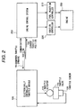
- a second embodiment of the invention is indicated in Fig. 2, in which engine speed monitor 280 indicated in Fig. 1 of the first embodiment of the invention is eliminated, and instead thereof, its engine speed is notified from engine control system 200 to electronically controlled throttle module 100 via communication line 150.
- the electronically controlled throttle module 100 only a means for knowing its engine speed is changed, and its operating principle is the same as in the case of Fig. 1. Further, such a case in which the electronically controlled throttle module 100 fails to learn the engine speed due to abnormality in communication line 150 corresponds to the case of malfunctioning of engine speed monitor 280 described with reference to Fig. 1.
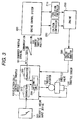
- a driver's intent input device 300 is typically represented by an acceleration pedal, and when the driver operates the pedal, it outputs a value in response to its control quantity.
- Electronically controlled throttle module 100 reads an output value from driver's intent input device 300, and obtains a first throttle target opening by means of a driver's intent/throttle opening converter 310. Further, an engine control demand opening converter 320 calculates a second throttle target opening on the basis of the throttle demand opening value received from engine control system 200 via communication line 150.
- a final throttle target opening arithmetic unit 330 adds the first throttle target opening and the second throttle target opening, and drives throttle actuator 110 in accordance with a value obtained as a result of addition.
- a predetermined value is used as a throttle demand opening value.
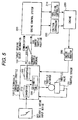
- a fourth embodiment of the invention which is a modification of the third embodiment above, will be described with reference to Fig. 4.
- a throttle demand opening buffer 321 is added to in comparison with the configuration of Fig. 3.
- Engine control demand opening converter 320 everytime it calculates a second throttle target opening on the basis of the throttle demand opening value received from engine control system 200 via communication line 150, stores a result of its calculation in throttle demand opening buffer memory 321.
- a second throttle target opening value is calculated on the basis of the values stored in throttle demand opening buffer memory 321.
- Target opening select information 153 is received from engine control system 200.
- Target opening select information 153 is either value of 1, 2 and 3, and each of which means as follows.
- a case where its target opening select information 153 is "1" corresponds to a normal case; another case where its target opening select information 153 is "2" corresponds to a case in which an output from driver's intent input device 300 is to be disregarded, wherein its throttle is controlled in accordance with the first throttle target opening requested by engine control system 200 even if the acceleration pedal is not pressed, which corresponds to a case of a cruising state; and the remaining case where its target opening select information 153 is "3" corresponds to a case in which the first throttle target opening received from engine control system 200 is to be disregarded, wherein the second throttle target opening that is calculated on the basis of the throttle demand opening value received from engine control system 200 via communication line 150 is disregarded due to detection of abnormality in communication with engine control system 200, even it the communication therebetween is recovered, thereby operating throttle valve 115 only according to a value read from driver's intent input device 300.
- the throttle valve is operated independently of the engine control system, it is enabled to detect occurrence of abnormality in the engine and execute a necessary fail-safe procedure.
Landscapes
- Engineering & Computer Science (AREA)
- General Engineering & Computer Science (AREA)
- Chemical & Material Sciences (AREA)
- Combustion & Propulsion (AREA)
- Mechanical Engineering (AREA)
- Computer Hardware Design (AREA)
- Microelectronics & Electronic Packaging (AREA)
- Electrical Control Of Air Or Fuel Supplied To Internal-Combustion Engine (AREA)
- Combined Controls Of Internal Combustion Engines (AREA)
- Control Of Throttle Valves Provided In The Intake System Or In The Exhaust System (AREA)
Abstract
Description
Claims (8)
- An engine equipment including an electronically controlled throttle system (100) and an engine control system (200), further comprising an engine behavior monitoring unit for monitoring engine behaviors, wherein said electronically controlled throttle system (100), when the same operates a throttle (115) to open or close without an instruction of throttle demand opening from said engine control system (200), analyzes a result of monitoring by said engine behavior monitoring unit, and if its engine behavior is judged to be abnormal from a deviation from a predetermined normal range of behaviors, executes a predetermined fail-safe procedure.
- An engine equipment including an electronically controlled throttle system (100) and an engine control system (200), further comprising an engine behavior monitoring unit for monitoring engine behaviors, wherein said electronically controlled throttle system (100), when the same operates a throttle (115) to open or close without an instruction of throttle demand opening from said engine control system (200), and if a result of monitoring the engine behaviors by said engine behavior monitoring unit is abnormal, executes a predetermined fail-safe procedure.
- An engine equipment including an electronically controlled throttle system (100) and an engine control system (200), said engine control system (200) comprising a built-in function to monitor engine behavior and notify a result of monitoring to said electronically controlled throttle system (100), wherein when said electronically controlled throttle system (100) operates a throttle (115) to open or close without an instruction from said engine control system (200), and if an abnormality is judged to have occurred on the basis of engine behavior information notified from said engine control system (200) and from a deviation of said engine behavior from a predetermined range of behaviors, said electronically controlled throttle system (100) executes a predetermined fail-safe operation.
- An electronically controlled throttle system according to claim 3, wherein said electronically controlled throttle system (100) executes a predetermined failsafe operation when said engine behavior information to be notified from said engine control system (200) fails to be received.
- An engine equipment comprising an electronically controlled throttle system (100) and an engine control system (200), wherein said electronically controlled throttle system (100) calculates a first throttle target opening on the basis of a value input from a driver's intent input device (300) and according to predetermined procedures, receives a second throttle target opening to be notified from said engine control system (200), calculates a final target throttle opening by adding said first and said second throttle target openings, and controls a throttle (115) to be positioned at said final target throttle opening.
- The engine equipment according to claim 5, wherein when the second throttle target opening is failed to be received, said electronically controlled throttle control system (100) sets up a predetermined value as the second throttle target opening.
- An engine equipment according to claim 5, wherein when the second throttle target opening fails to be notified, the electronically controlled throttle system (100) sets up a value that is the last second throttle target opening obtained in precedence and is changed at a predetermined rate with an elapse of time as its second throttle target opening.
- An engine equipment according to claim 5, wherein the electronically controlled throttle system (100) is notified of target throttle select information, adds a weight to either of a first and a second throttle target openings on the basis of said target throttle select information, and calculates a final target throttle opening.
Priority Applications (1)
| Application Number | Priority Date | Filing Date | Title |
|---|---|---|---|
| EP07009739A EP1816329A2 (en) | 1999-08-06 | 2000-07-25 | Electronically controlled throttle control apparatus |
Applications Claiming Priority (2)
| Application Number | Priority Date | Filing Date | Title |
|---|---|---|---|
| JP22341799 | 1999-08-06 | ||
| JP22341799A JP4012654B2 (en) | 1999-08-06 | 1999-08-06 | Engine equipment control device and electronically controlled throttle system |
Related Child Applications (1)
| Application Number | Title | Priority Date | Filing Date |
|---|---|---|---|
| EP07009739A Division EP1816329A2 (en) | 1999-08-06 | 2000-07-25 | Electronically controlled throttle control apparatus |
Publications (3)
| Publication Number | Publication Date |
|---|---|
| EP1074712A2 true EP1074712A2 (en) | 2001-02-07 |
| EP1074712A3 EP1074712A3 (en) | 2003-03-05 |
| EP1074712B1 EP1074712B1 (en) | 2007-07-25 |
Family
ID=16797827
Family Applications (2)
| Application Number | Title | Priority Date | Filing Date |
|---|---|---|---|
| EP07009739A Withdrawn EP1816329A2 (en) | 1999-08-06 | 2000-07-25 | Electronically controlled throttle control apparatus |
| EP00115040A Expired - Lifetime EP1074712B1 (en) | 1999-08-06 | 2000-07-25 | Electronic throttle control system |
Family Applications Before (1)
| Application Number | Title | Priority Date | Filing Date |
|---|---|---|---|
| EP07009739A Withdrawn EP1816329A2 (en) | 1999-08-06 | 2000-07-25 | Electronically controlled throttle control apparatus |
Country Status (4)
| Country | Link |
|---|---|
| US (2) | US6352064B1 (en) |
| EP (2) | EP1816329A2 (en) |
| JP (1) | JP4012654B2 (en) |
| DE (1) | DE60035646T2 (en) |
Families Citing this family (13)
| Publication number | Priority date | Publication date | Assignee | Title |
|---|---|---|---|---|
| JP3791434B2 (en) * | 2002-02-28 | 2006-06-28 | 株式会社デンソー | Electronic control device for vehicle |
| DE10232876A1 (en) * | 2002-07-19 | 2004-01-29 | Robert Bosch Gmbh | Method and device for determining a stop-free extreme position of an actuator of an internal combustion engine |
| JP2004116435A (en) * | 2002-09-27 | 2004-04-15 | Hitachi Ltd | Automotive control device |
| US6874470B2 (en) | 2003-03-04 | 2005-04-05 | Visteon Global Technologies, Inc. | Powered default position for motorized throttle |
| JP2005188309A (en) * | 2003-12-24 | 2005-07-14 | Denso Corp | Throttle abnormality determination device |
| US7114487B2 (en) * | 2004-01-16 | 2006-10-03 | Ford Motor Company | Ice-breaking, autozero and frozen throttle plate detection at power-up for electronic motorized throttle |
| JP2006152824A (en) * | 2004-11-25 | 2006-06-15 | Denso Corp | Throttle control system |
| DE102006028695B4 (en) * | 2005-06-23 | 2017-11-30 | Denso Corporation | Electronic control system with malfunction monitoring |
| JP4827535B2 (en) * | 2006-01-20 | 2011-11-30 | 日立オートモティブシステムズ株式会社 | Electronic control unit for automobile |
| DE602007007586D1 (en) * | 2007-05-25 | 2010-08-19 | Magneti Marelli Spa | A control method for a motor vehicle which, in the event of a defect, causes the vehicle to operate at reduced power |
| DE102007049687B4 (en) * | 2007-10-17 | 2009-07-30 | Pierburg Gmbh | Engine positioning device |
| SE536886C2 (en) * | 2010-08-31 | 2014-10-21 | Scania Cv Ab | Method of initiating an adjustment of a damper |
| SE536887C2 (en) * | 2010-08-31 | 2014-10-21 | Scania Cv Ab | Method of adjusting a damper |
Family Cites Families (15)
| Publication number | Priority date | Publication date | Assignee | Title |
|---|---|---|---|---|
| JP2518319B2 (en) * | 1987-11-16 | 1996-07-24 | 日本電装株式会社 | Fail-safe device for internal combustion engine for vehicles |
| US5154150A (en) * | 1991-02-13 | 1992-10-13 | John Vieira | Remote-start, fail-safe, dual-mode, engine throttle control |
| JP2666229B2 (en) * | 1992-03-30 | 1997-10-22 | 本田技研工業株式会社 | Abnormality diagnosis device for internal combustion engine |
| US5447133A (en) * | 1992-10-23 | 1995-09-05 | Nippondenso Co., Ltd. | Throttle control apparatus for an internal combustion engine |
| JP3216346B2 (en) * | 1993-08-26 | 2001-10-09 | 株式会社デンソー | Throttle valve control device for internal combustion engine |
| JP3338195B2 (en) * | 1994-08-10 | 2002-10-28 | 本田技研工業株式会社 | Intake air amount control device for internal combustion engine |
| DE19719518B4 (en) * | 1997-05-09 | 2008-04-30 | Robert Bosch Gmbh | Method and device for controlling a drive unit of a motor vehicle |
| KR100284795B1 (en) * | 1997-05-26 | 2001-03-15 | 하나와 요시카즈 | Idle speed control device of the engine |
| JP3566517B2 (en) * | 1997-11-11 | 2004-09-15 | 三菱電機株式会社 | Drive control device for vehicle engine |
| US6209518B1 (en) * | 1998-08-05 | 2001-04-03 | Unisia Jecs Corporation | Method and apparatus for fail safe control of an electronically controlled throttle valve of an internal combustion engine |
| JP3694406B2 (en) * | 1998-08-28 | 2005-09-14 | 株式会社日立製作所 | Fail-safe control device for electric throttle type internal combustion engine |
| JP3627532B2 (en) * | 1998-10-02 | 2005-03-09 | 日産自動車株式会社 | Engine control device |
| JP2000192838A (en) * | 1998-12-25 | 2000-07-11 | Mitsubishi Electric Corp | Automotive engine control device |
| JP3061795B1 (en) * | 1999-05-14 | 2000-07-10 | 三菱電機株式会社 | Engine intake air control system |
| JP2002122036A (en) * | 2000-10-16 | 2002-04-26 | Aisan Ind Co Ltd | Electronic throttle control |
-
1999
- 1999-08-06 JP JP22341799A patent/JP4012654B2/en not_active Expired - Fee Related
-
2000
- 2000-07-25 DE DE60035646T patent/DE60035646T2/en not_active Expired - Fee Related
- 2000-07-25 EP EP07009739A patent/EP1816329A2/en not_active Withdrawn
- 2000-07-25 EP EP00115040A patent/EP1074712B1/en not_active Expired - Lifetime
- 2000-08-07 US US09/633,896 patent/US6352064B1/en not_active Expired - Fee Related
-
2002
- 2002-02-21 US US10/078,367 patent/US6619259B2/en not_active Expired - Fee Related
Also Published As
| Publication number | Publication date |
|---|---|
| JP4012654B2 (en) | 2007-11-21 |
| EP1816329A2 (en) | 2007-08-08 |
| EP1074712A3 (en) | 2003-03-05 |
| EP1074712B1 (en) | 2007-07-25 |
| US20020073962A1 (en) | 2002-06-20 |
| US6352064B1 (en) | 2002-03-05 |
| DE60035646D1 (en) | 2007-09-06 |
| DE60035646T2 (en) | 2008-05-21 |
| JP2001050080A (en) | 2001-02-23 |
| US6619259B2 (en) | 2003-09-16 |
Similar Documents
| Publication | Publication Date | Title |
|---|---|---|
| US5673668A (en) | Method and apparatus for electronic throttle monitoring | |
| JP3847664B2 (en) | In-vehicle engine controller | |
| US5429092A (en) | Throttle control system | |
| JP4409800B2 (en) | Engine control device | |
| US6352064B1 (en) | Electrically controlled throttle control system | |
| US8862344B2 (en) | Clutch actuator and method for the control thereof | |
| JP2002371897A (en) | Engine intake air control system | |
| US20200010066A1 (en) | Abnormality Diagnostic Device and Abnormality Diagnostic Method for Booster | |
| US10385935B2 (en) | Method for increasing the availability of a hybrid separating clutch in a hybrid drive train of a motor vehicle | |
| US5365904A (en) | Redundant speed sensor for engine control | |
| US7156063B2 (en) | Starter device for an internal combustion engine as well as a method for starting an internal combustion engine | |
| US6662780B2 (en) | Method for controlling limp-home of vehicular electronic throttle system | |
| JP2011032903A (en) | Control device of vehicle | |
| JP3688132B2 (en) | Throttle valve control device | |
| US20020107631A1 (en) | Electronic control system and method having monitor program monitoring function | |
| KR20180042640A (en) | Mehod for diagnosing failure of power stage of electric waste gate actuator | |
| US11274713B2 (en) | Mean rate decision method for clutch motor | |
| JPH05263693A (en) | Fail-safe device for engine with electronic throttle control device | |
| JP2002038978A (en) | Throttle valve control device | |
| JP3547619B2 (en) | Internal combustion engine control device | |
| JP3076577B2 (en) | Motor type constant speed traveling device | |
| US6837216B1 (en) | Electronic throttle control system | |
| JPS61291224A (en) | Automatic car-speed controller | |
| JPH0732186Y2 (en) | Air conditioner control device | |
| JPH07301655A (en) | Disconnection diagnosis device for duty control solenoid |
Legal Events
| Date | Code | Title | Description |
|---|---|---|---|
| PUAI | Public reference made under article 153(3) epc to a published international application that has entered the european phase |
Free format text: ORIGINAL CODE: 0009012 |
|
| AK | Designated contracting states |
Kind code of ref document: A2 Designated state(s): AT BE CH CY DE DK ES FI FR GB GR IE IT LI LU MC NL PT SE |
|
| AX | Request for extension of the european patent |
Free format text: AL;LT;LV;MK;RO;SI |
|
| RIC1 | Information provided on ipc code assigned before grant |
Free format text: 7F 02D 11/10 A, 7F 02D 41/22 B |
|
| PUAL | Search report despatched |
Free format text: ORIGINAL CODE: 0009013 |
|
| AK | Designated contracting states |
Designated state(s): AT BE CH CY DE DK ES FI FR GB GR IE IT LI LU MC NL PT SE Kind code of ref document: A3 Designated state(s): AT BE CH CY DE DK ES FI FR GB GR IE IT LI LU MC NL PT SE |
|
| AX | Request for extension of the european patent |
Extension state: AL LT LV MK RO SI |
|
| 17P | Request for examination filed |
Effective date: 20030702 |
|
| AKX | Designation fees paid |
Designated state(s): DE FR GB IT |
|
| GRAP | Despatch of communication of intention to grant a patent |
Free format text: ORIGINAL CODE: EPIDOSNIGR1 |
|
| RIN1 | Information on inventor provided before grant (corrected) |
Inventor name: TOMITA, TSUGIO Inventor name: NAKANO, SYUUICHI Inventor name: ONO, KOICHI Inventor name: WATABE, MITSURU |
|
| GRAS | Grant fee paid |
Free format text: ORIGINAL CODE: EPIDOSNIGR3 |
|
| GRAA | (expected) grant |
Free format text: ORIGINAL CODE: 0009210 |
|
| RAP1 | Party data changed (applicant data changed or rights of an application transferred) |
Owner name: HITACHI CAR ENGINEERING CO., LTD. Owner name: HITACHI, LTD. |
|
| AK | Designated contracting states |
Kind code of ref document: B1 Designated state(s): DE FR GB IT |
|
| REG | Reference to a national code |
Ref country code: GB Ref legal event code: FG4D |
|
| REF | Corresponds to: |
Ref document number: 60035646 Country of ref document: DE Date of ref document: 20070906 Kind code of ref document: P |
|
| EN | Fr: translation not filed | ||
| PLBE | No opposition filed within time limit |
Free format text: ORIGINAL CODE: 0009261 |
|
| STAA | Information on the status of an ep patent application or granted ep patent |
Free format text: STATUS: NO OPPOSITION FILED WITHIN TIME LIMIT |
|
| 26N | No opposition filed |
Effective date: 20080428 |
|
| PG25 | Lapsed in a contracting state [announced via postgrant information from national office to epo] |
Ref country code: FR Free format text: LAPSE BECAUSE OF FAILURE TO SUBMIT A TRANSLATION OF THE DESCRIPTION OR TO PAY THE FEE WITHIN THE PRESCRIBED TIME-LIMIT Effective date: 20080321 |
|
| PGFP | Annual fee paid to national office [announced via postgrant information from national office to epo] |
Ref country code: GB Payment date: 20090707 Year of fee payment: 10 Ref country code: DE Payment date: 20090824 Year of fee payment: 10 |
|
| PG25 | Lapsed in a contracting state [announced via postgrant information from national office to epo] |
Ref country code: IT Free format text: LAPSE BECAUSE OF NON-PAYMENT OF DUE FEES Effective date: 20070731 |
|
| GBPC | Gb: european patent ceased through non-payment of renewal fee |
Effective date: 20100725 |
|
| PG25 | Lapsed in a contracting state [announced via postgrant information from national office to epo] |
Ref country code: DE Free format text: LAPSE BECAUSE OF NON-PAYMENT OF DUE FEES Effective date: 20110201 |
|
| REG | Reference to a national code |
Ref country code: DE Ref legal event code: R119 Ref document number: 60035646 Country of ref document: DE Effective date: 20110201 |
|
| PG25 | Lapsed in a contracting state [announced via postgrant information from national office to epo] |
Ref country code: GB Free format text: LAPSE BECAUSE OF NON-PAYMENT OF DUE FEES Effective date: 20100725 |