EP1074601B1 - Organic electroluminescent material and electroluminescent device using the same - Google Patents
Organic electroluminescent material and electroluminescent device using the same Download PDFInfo
- Publication number
- EP1074601B1 EP1074601B1 EP00116726.1A EP00116726A EP1074601B1 EP 1074601 B1 EP1074601 B1 EP 1074601B1 EP 00116726 A EP00116726 A EP 00116726A EP 1074601 B1 EP1074601 B1 EP 1074601B1
- Authority
- EP
- European Patent Office
- Prior art keywords
- substituted
- alkyl
- independently
- aromatic hydrocarbon
- aromatic heterocyclic
- Prior art date
- Legal status (The legal status is an assumption and is not a legal conclusion. Google has not performed a legal analysis and makes no representation as to the accuracy of the status listed.)
- Expired - Lifetime
Links
- 0 C***C(CC1C(C)C1)c1c(C)ccc(C)c1 Chemical compound C***C(CC1C(C)C1)c1c(C)ccc(C)c1 0.000 description 15
- GISVICWQYMUPJF-UHFFFAOYSA-N Cc1cc(C)c(C=O)cc1 Chemical compound Cc1cc(C)c(C=O)cc1 GISVICWQYMUPJF-UHFFFAOYSA-N 0.000 description 1
Images


Classifications
-
- C—CHEMISTRY; METALLURGY
- C09—DYES; PAINTS; POLISHES; NATURAL RESINS; ADHESIVES; COMPOSITIONS NOT OTHERWISE PROVIDED FOR; APPLICATIONS OF MATERIALS NOT OTHERWISE PROVIDED FOR
- C09K—MATERIALS FOR MISCELLANEOUS APPLICATIONS, NOT PROVIDED FOR ELSEWHERE
- C09K11/00—Luminescent materials, e.g. electroluminescent or chemiluminescent
- C09K11/06—Luminescent materials, e.g. electroluminescent or chemiluminescent containing organic luminescent materials
-
- C—CHEMISTRY; METALLURGY
- C07—ORGANIC CHEMISTRY
- C07C—ACYCLIC OR CARBOCYCLIC COMPOUNDS
- C07C211/00—Compounds containing amino groups bound to a carbon skeleton
- C07C211/43—Compounds containing amino groups bound to a carbon skeleton having amino groups bound to carbon atoms of six-membered aromatic rings of the carbon skeleton
- C07C211/54—Compounds containing amino groups bound to a carbon skeleton having amino groups bound to carbon atoms of six-membered aromatic rings of the carbon skeleton having amino groups bound to two or three six-membered aromatic rings
-
- C—CHEMISTRY; METALLURGY
- C07—ORGANIC CHEMISTRY
- C07C—ACYCLIC OR CARBOCYCLIC COMPOUNDS
- C07C211/00—Compounds containing amino groups bound to a carbon skeleton
- C07C211/43—Compounds containing amino groups bound to a carbon skeleton having amino groups bound to carbon atoms of six-membered aromatic rings of the carbon skeleton
- C07C211/54—Compounds containing amino groups bound to a carbon skeleton having amino groups bound to carbon atoms of six-membered aromatic rings of the carbon skeleton having amino groups bound to two or three six-membered aromatic rings
- C07C211/56—Compounds containing amino groups bound to a carbon skeleton having amino groups bound to carbon atoms of six-membered aromatic rings of the carbon skeleton having amino groups bound to two or three six-membered aromatic rings the carbon skeleton being further substituted by halogen atoms or by nitro or nitroso groups
-
- C—CHEMISTRY; METALLURGY
- C07—ORGANIC CHEMISTRY
- C07C—ACYCLIC OR CARBOCYCLIC COMPOUNDS
- C07C211/00—Compounds containing amino groups bound to a carbon skeleton
- C07C211/43—Compounds containing amino groups bound to a carbon skeleton having amino groups bound to carbon atoms of six-membered aromatic rings of the carbon skeleton
- C07C211/57—Compounds containing amino groups bound to a carbon skeleton having amino groups bound to carbon atoms of six-membered aromatic rings of the carbon skeleton having amino groups bound to carbon atoms of six-membered aromatic rings being part of condensed ring systems of the carbon skeleton
-
- C—CHEMISTRY; METALLURGY
- C07—ORGANIC CHEMISTRY
- C07C—ACYCLIC OR CARBOCYCLIC COMPOUNDS
- C07C217/00—Compounds containing amino and etherified hydroxy groups bound to the same carbon skeleton
- C07C217/78—Compounds containing amino and etherified hydroxy groups bound to the same carbon skeleton having amino groups and etherified hydroxy groups bound to carbon atoms of six-membered aromatic rings of the same carbon skeleton
- C07C217/80—Compounds containing amino and etherified hydroxy groups bound to the same carbon skeleton having amino groups and etherified hydroxy groups bound to carbon atoms of six-membered aromatic rings of the same carbon skeleton having amino groups and etherified hydroxy groups bound to carbon atoms of non-condensed six-membered aromatic rings
-
- C—CHEMISTRY; METALLURGY
- C07—ORGANIC CHEMISTRY
- C07C—ACYCLIC OR CARBOCYCLIC COMPOUNDS
- C07C217/00—Compounds containing amino and etherified hydroxy groups bound to the same carbon skeleton
- C07C217/78—Compounds containing amino and etherified hydroxy groups bound to the same carbon skeleton having amino groups and etherified hydroxy groups bound to carbon atoms of six-membered aromatic rings of the same carbon skeleton
- C07C217/80—Compounds containing amino and etherified hydroxy groups bound to the same carbon skeleton having amino groups and etherified hydroxy groups bound to carbon atoms of six-membered aromatic rings of the same carbon skeleton having amino groups and etherified hydroxy groups bound to carbon atoms of non-condensed six-membered aromatic rings
- C07C217/82—Compounds containing amino and etherified hydroxy groups bound to the same carbon skeleton having amino groups and etherified hydroxy groups bound to carbon atoms of six-membered aromatic rings of the same carbon skeleton having amino groups and etherified hydroxy groups bound to carbon atoms of non-condensed six-membered aromatic rings of the same non-condensed six-membered aromatic ring
- C07C217/92—Compounds containing amino and etherified hydroxy groups bound to the same carbon skeleton having amino groups and etherified hydroxy groups bound to carbon atoms of six-membered aromatic rings of the same carbon skeleton having amino groups and etherified hydroxy groups bound to carbon atoms of non-condensed six-membered aromatic rings of the same non-condensed six-membered aromatic ring the nitrogen atom of at least one of the amino groups being further bound to a carbon atom of a six-membered aromatic ring
-
- H—ELECTRICITY
- H05—ELECTRIC TECHNIQUES NOT OTHERWISE PROVIDED FOR
- H05B—ELECTRIC HEATING; ELECTRIC LIGHT SOURCES NOT OTHERWISE PROVIDED FOR; CIRCUIT ARRANGEMENTS FOR ELECTRIC LIGHT SOURCES, IN GENERAL
- H05B33/00—Electroluminescent light sources
- H05B33/12—Light sources with substantially two-dimensional [2D] radiating surfaces
- H05B33/14—Light sources with substantially two-dimensional [2D] radiating surfaces characterised by the chemical or physical composition or the arrangement of the electroluminescent material, or by the simultaneous addition of the electroluminescent material in or onto the light source
-
- H—ELECTRICITY
- H10—SEMICONDUCTOR DEVICES; ELECTRIC SOLID-STATE DEVICES NOT OTHERWISE PROVIDED FOR
- H10K—ORGANIC ELECTRIC SOLID-STATE DEVICES
- H10K85/00—Organic materials used in the body or electrodes of devices covered by this subclass
- H10K85/60—Organic compounds having low molecular weight
- H10K85/631—Amine compounds having at least two aryl rest on at least one amine-nitrogen atom, e.g. triphenylamine
-
- H—ELECTRICITY
- H10—SEMICONDUCTOR DEVICES; ELECTRIC SOLID-STATE DEVICES NOT OTHERWISE PROVIDED FOR
- H10K—ORGANIC ELECTRIC SOLID-STATE DEVICES
- H10K85/00—Organic materials used in the body or electrodes of devices covered by this subclass
- H10K85/60—Organic compounds having low molecular weight
- H10K85/631—Amine compounds having at least two aryl rest on at least one amine-nitrogen atom, e.g. triphenylamine
- H10K85/633—Amine compounds having at least two aryl rest on at least one amine-nitrogen atom, e.g. triphenylamine comprising polycyclic condensed aromatic hydrocarbons as substituents on the nitrogen atom
-
- C—CHEMISTRY; METALLURGY
- C09—DYES; PAINTS; POLISHES; NATURAL RESINS; ADHESIVES; COMPOSITIONS NOT OTHERWISE PROVIDED FOR; APPLICATIONS OF MATERIALS NOT OTHERWISE PROVIDED FOR
- C09K—MATERIALS FOR MISCELLANEOUS APPLICATIONS, NOT PROVIDED FOR ELSEWHERE
- C09K2211/00—Chemical nature of organic luminescent or tenebrescent compounds
- C09K2211/10—Non-macromolecular compounds
- C09K2211/1003—Carbocyclic compounds
- C09K2211/1014—Carbocyclic compounds bridged by heteroatoms, e.g. N, P, Si or B
-
- H—ELECTRICITY
- H10—SEMICONDUCTOR DEVICES; ELECTRIC SOLID-STATE DEVICES NOT OTHERWISE PROVIDED FOR
- H10K—ORGANIC ELECTRIC SOLID-STATE DEVICES
- H10K2102/00—Constructional details relating to the organic devices covered by this subclass
- H10K2102/10—Transparent electrodes, e.g. using graphene
- H10K2102/101—Transparent electrodes, e.g. using graphene comprising transparent conductive oxides [TCO]
- H10K2102/103—Transparent electrodes, e.g. using graphene comprising transparent conductive oxides [TCO] comprising indium oxides, e.g. ITO
-
- H—ELECTRICITY
- H10—SEMICONDUCTOR DEVICES; ELECTRIC SOLID-STATE DEVICES NOT OTHERWISE PROVIDED FOR
- H10K—ORGANIC ELECTRIC SOLID-STATE DEVICES
- H10K50/00—Organic light-emitting devices
- H10K50/10—OLEDs or polymer light-emitting diodes [PLED]
- H10K50/11—OLEDs or polymer light-emitting diodes [PLED] characterised by the electroluminescent [EL] layers
-
- H—ELECTRICITY
- H10—SEMICONDUCTOR DEVICES; ELECTRIC SOLID-STATE DEVICES NOT OTHERWISE PROVIDED FOR
- H10K—ORGANIC ELECTRIC SOLID-STATE DEVICES
- H10K50/00—Organic light-emitting devices
- H10K50/10—OLEDs or polymer light-emitting diodes [PLED]
- H10K50/14—Carrier transporting layers
-
- H—ELECTRICITY
- H10—SEMICONDUCTOR DEVICES; ELECTRIC SOLID-STATE DEVICES NOT OTHERWISE PROVIDED FOR
- H10K—ORGANIC ELECTRIC SOLID-STATE DEVICES
- H10K85/00—Organic materials used in the body or electrodes of devices covered by this subclass
- H10K85/30—Coordination compounds
- H10K85/321—Metal complexes comprising a group IIIA element, e.g. Tris (8-hydroxyquinoline) gallium [Gaq3]
- H10K85/324—Metal complexes comprising a group IIIA element, e.g. Tris (8-hydroxyquinoline) gallium [Gaq3] comprising aluminium, e.g. Alq3
-
- Y—GENERAL TAGGING OF NEW TECHNOLOGICAL DEVELOPMENTS; GENERAL TAGGING OF CROSS-SECTIONAL TECHNOLOGIES SPANNING OVER SEVERAL SECTIONS OF THE IPC; TECHNICAL SUBJECTS COVERED BY FORMER USPC CROSS-REFERENCE ART COLLECTIONS [XRACs] AND DIGESTS
- Y10—TECHNICAL SUBJECTS COVERED BY FORMER USPC
- Y10S—TECHNICAL SUBJECTS COVERED BY FORMER USPC CROSS-REFERENCE ART COLLECTIONS [XRACs] AND DIGESTS
- Y10S428/00—Stock material or miscellaneous articles
- Y10S428/917—Electroluminescent
Definitions
- the present invention relates to an organic-electroluminescence (EL) device used for planar light sources and displays, and the organic EL material therefor.
- EL organic-electroluminescence
- An organic EL device has been attracting attention as a planar display element.
- the organic EL device with two or more organic layers has much improved light-emitting efficiency, emitting light of high brightness at a voltage of 10 V or less applied thereto ( Applied Physics Letters, vol. 51, pp. 913, 1987 and vol. 56, pp. 799, 1990 ).
- It generally comprises an anode, hole transport region, EL light-emitting region, electron transport region and cathode as the basic structure. It may lack one of the hole and electron transport regions, or both. Each region may consist of one layer, or two or more layers.
- triphenylamine derivatives for the hole transport region.
- 1,1-bis-(4-diparatolylaminophenyl)cyclohexane and N,N'-diphenyl-N,N'-bis(3-methylphenyl)-1,1'-biphenyl-4,4'-diamine are preferably used, because of their good hole injection and film-making characteristics.
- Japanese Patent Publication No. SHO 64-7635 discloses use of a porphyrin compound for the hole transport layer.
- crystallization or agglomeration of the layer also occurs after the device is assembled, deteriorating its functions.
- Japanese Patent Publication No. HEI 7-110940 ( 110940/1995 B ) and Applied Physics Letters, vol. 65, pp. 807, 1994 disclose use of a starburst type tertiary amine derivatives for the hole transport material. However, it also fails to give the device which can continuously emit sufficiently bright light.
- Japanese Patent No. 2597377 discloses an organic-EL device structure comprising two hole transport layers of hole injection type compounds, one being of a porphyrin compound and the other of an aromatic tertiary amine from the anode side, in order to reduce pinholes and thereby to improve device stability.
- this structure shows insufficient improvement in device stability.
- the conventional organic EL device is insufficient in brightness, when it is to be used for light-emitting devices, e.g., full-color display, and is required to have higher brightness.
- the organic EL device is less durable than other types of light-emitting devices, and insufficient in brightness-related properties, which have greatly retarded its commercialization.
- the present invention has been developed to solve the above problems, and thereby to provide an organic EL device of longer serviceability and emitting light of high brightness.
- the organic electroluminescence material characterized by containing a compound shown by the following general formula (A-I): wherein, A 1 to A 3 are independently, each a substituent shown by the general formula (A-II). which may be the same or different.
- the organic electroluminescence material characterized by containing a compound shown by the following general formula (A-III) (Except that the substituent shown by the general formula (A-V) is at the site of Y 3 and, at the same time, the substituent shown by the formula -NAr 1 Ar 2 is at the site of Y 8 .): wherein, B 1 to B 3 are independently, each a substituent shown by the general formula (A-IV). which may be the same or different.
- the organic electroluminescence material characterized by containing a compound shown by the following general formula (A-VI): wherein, D 1 to D 3 are independently, each a substituent shown by the general formula (A-VII). They may be the same or different.
- the organic electroluminescence material characterized by containing a compound shown by the following general formula (B-I): wherein, a 1 , b 1 and b 2 are independently, each an aryl group which is substituted, a 1 having at least one substituent shown by the general formula (B-II), each of b 1 and b 2 having at least one substituent shown by the general formula (B-III), and b 1 and b 2 may be the same or different:
- organic electroluminescence material wherein at least one material of said organic electroluminescence materials according to any one of claims 1 to 4, is dispersed in a polymer binder.
- organic electroluminescence device comprising one or more layers of organic thin films put between the anode and cathode, wherein at least one of said layers is composed of at least one of the organic electroluminescence materials according to any one of claims 1 to 4.
- organic electroluminescence device of claim 6 wherein at least one of said layers is composed of at least one of the organic electroluminescence materials according to any one of claims 1 to 4, and 2 to 500 nm thick.
- the organic electroluminescence device of claim 6 wherein said hole transport layer contains a first and second hole transport layer facing the anode and light-emitting layer sides, respectively, and said first hole transport layer is composed of at least one of the organic electroluminescence materials according to any one of claims 1 to 4.
- organic electroluminescence device of claim 10 wherein said second hole transport layer contains an aromatic tertiary amine compound.
- Fig. 1 (a) shows a section of an organic EL device which uses an organic EL material of the present invention, where reference numeral 11 denotes a glass substrate; reference numeral 12 denotes an anode; reference numeral 13 denotes a hole transport layer; reference numeral 14 denotes a light-emitting layer; reference numeral 15 denotes an electron transport layer; and reference numeral 16 denotes a cathode.
- the organic EL material of the present invention is used at least one of the hole transport layer 13, light-emitting layer 14, and electron transport layer 15.
- the organic EL device of the present invention may dispense with the hole transport layer 13 and/or electron transport layer 15.
- Fig. 2 (a) shows the device which dispenses with the electron transport layer 15
- Fig. 3 shows the device which dispenses with both layers.
- the hole transport layer 13 may be divided into the first hole transport layer 13a on the anodic side and second hole transport layer 13b on the light-emitting device side, as shown in Figs. 1(b) and 2(b) , where the former is made of the organic EL material of the present invention and the latter of a known organic material.
- An anode interface layer may be provided between the anode 12 and hole tranport layer 13, or anode 12 and first hole transport layer 13a.
- Fig. 4 shows an example of the anode interface layer provided between the anode 12 and hole transport layer 13 for the organic EL device, shown in Fig. 2 (a) .
- halogen atoms for the substituents shown by the general formula (A-II), (A-IV), (A-V), (A-VII), (B-II) or (B-III) include fluorine, chlorine, bromine and iodine.
- the amino group or substituted amino group is shown bfy the general formula -NX 1 X 2 , wherein X 1 and X 2 are independently, each hydrogen atom or methyl, ethyl, propyl, isopropyl, n-butyl, s-butyl, isobutyl, t-butyl, n-pentyl, n-hexyl, n-heptyl, n-octyl, hydroxymethyl, 1-hydroxyethyl, 2-hydroxyethyl, 2-hydroxyisobutyl, 1, 2-dihydroxyethyl, 1,3-dihydroxyisopropyl, 2,3-dihydroxy-t-butyl, 1,2,3-trihydroxypropyl, chloromethyl, 1-chloroethyl, 2-chloroethyl, 2-chloroisobutyl, 1,2-dichloroethyl, 1,3-dichloroisopropyl, 2,3-d
- alkyl or substituted alkyl group useful for the present invention include(s) methyl, ethyl, propyl, isopropyl, n-butyl, s-butyl, isobutyl, t-butyl, n-pentyl, n-hexyl, n-heptyl, n-octyl, hydroxymethyl, 1-hydroxyethyl, 2-hydroxyethyl, 2-hydroxyisobutyl, 1,2-dihydroxyethyl, 1,3-dihydroxyisopropyl, 2,3-dihydroxy-t-butyl, 1,2,3-trihydroxypropyl, chloromethyl, 1-chloroethyl, 2-chloroethyl, 2-chloroisobutyl, 1,2-dichloroethyl, 1,3-dichloroisopropyl, 2,3-dichloro-t-butyl, 1,2,3-trichloropropyl, brom
- the alkenyl or substituted alkenyl group, useful for the present invention includes vinyl, allyl, 1-butenyl, 2-butenyl, 3-butenyl, 1,3-butanedienyl, 1-methylvinyl, 1-methylallyl, 1,1-dimethylallyl, 2-methylallyl, 1-phenylallyl, 2-phenylallyl, 3-phenylallyl, 3,3-diphenylallyl, 1,2-dimethylallyl, 1-phenyl-1-butenyl, and 3-phenyl-1-butenyl.
- cycloalkyl or substituted cycloalkyl group useful for the present invention include cyclopropyl, cyclobutyl, cyclopentyl, cyclohexyl, and 4-methylcyclohexyl group.
- the alkoxy or substituted alkoxy group is represented by the general formula -OY.
- the groups represented by Y useful for the present invention include methyl, ethyl, propyl, isopropyl, n-butyl, s-butyl, isobutyl, t-butyl, n-pentyl, n-hexyl, n-heptyl, n-octyl, hydroxymethyl, 1-hydroxyethyl, 2-hydroxyethyl, 2-hydroxyisobutyl, 1,2-dihydroxyethyl, 1,3-dihydroxyisopropyl, 2,3-dihydroxy-t-butyl, 1,2,3-trihydroxypropyl, chloromethyl, 1-chloroethyl, 2-chloroethyl, 2-chloroisobutyl, 1,2-dichloroethyl, 1,3-dichloroisopropyl, 2,3-dichloro-t-buty
- the aromatic hydrocarbon or substituted aromatic hydrocarbon group(s), useful for the present invention includes phenyl, 1-naphthyl, 2-naphthyl, 1-anthryl, 2-anthryl, 9-anthryl, 1-phenanthryl, 2-phenanthryl, 3-phenanthryl, 4-phenanthryl, 9-phenanthryl, 1-naphthacenyl, 2-naphthacenyl, 9-naphthacenyl, 1-pyrenyl, 2-pyrenyl, 4-pyrenyl, 2-biphenylyl, 3-biphenylyl, 4-biphenylyl, p-terphenyl-4-yl, p-terphenyl-3-yl, p-terphenyl-2-yl, m-terphenyl-4-yl, m-terphenyl-3-yl, m-terphenyl-2-yl, o-tolyl, m-tolyl, p
- aromatic heterocyclic or substituted aromatic heterocyclic group(s), useful for the present invention include 1-pyrrolyl, 2-pyrrolyl, 3-pyrrolyl, pyrazinyl, 2-pyridinyl, 3-pyridinyl, 4-pyridinyl, 1-indolyl, 2-indolyl, 3-indolyl, 4-indolyl, 5-indolyl, 6-indolyl, 7-indolyl, 1-isoindolyl, 2-isoindolyl, 3-isoindolyl, 4-isoindolyl, 5-isoindolyl, 6-isoindolyl, 7-isoindolyl, 2-furyl, 3-furyl, 2-benzofuranyl, 3-benzofuranyl, 4-benzofuranyl, 5-benzofuranyl, 6-benzofuranyl, 7-benzofuranyl, 1-isobenzofuranyl, 3-isobenzofuranyl, 4-is
- the aralkyl or substituted aralkyl group(s), useful for the present invention include(s) benzyl, 1-phenylethyl, 2-phenylethyl, 1-phenylisopropyl, 2-phenylisopropyl, phenyl-t-butyl, a -naphthylmethyl, 1- a -naphthylethyl, 2- ⁇ -naphthylethyl, 1- a -naphthylisopropyl, 2- ⁇ - naphthylisopropyl, ⁇ -naphthylmethyl, 1- ⁇ -naphthylethyl, 2- ⁇ -naphthylethyl, 1- ⁇ -naphthylisopropyl, 2- ⁇ -naphthylisopropyl, 1-pyrrolylmethyl, 2-(1-pyrrolyl)
- the aryloxy or substituted aryloxy group(s), which may be substituted, is represented by the general formula -OZ.
- the groups represented by Z useful for the present invention include phenyl, 1-naphthyl, 2-naphthyl, 1-anthryl, 2-anthryl, 9-anthryl, 1-phenanthryl, 2-phenanthryl, 3-phenanthryl, 4-phenanthryl, 9-phenanthryl, 1-naphthacenyl, 2-naphthacenyl, 9-naphthacenyl, 1-pyrenyl, 2-pyrenyl, 4-pyrenyl, 2-biphenylyl, 3-biphenylyl, 4-biphenylyl, p-terphenyl-4-yl, p-terphenyl-3-yl, p-terphenyl-2-yl, m-terphenyl-4-yl, m-terphenyl-3-yl, m
- the alkoxy carbonyl or substituted alkoxy carbonyl group(s), is represented by the general formula -COOY.
- the groups represented by Y useful for the present invention include methyl, ethyl, propyl, isopropyl, n-butyl, s-butyl, isobutyl, t-butyl, n-pentyl, n-hexyl, n-heptyl, n-octyl, hydroxymethyl, 1-hydroxyethyl, 2-hydroxyethyl, 2-hydroxyisobutyl, 1,2-dihydroxyethyl, 1,3-dihydroxyisopropyl, 2,3-dihydroxy-t-butyl, 1,2,3-trihydroxypropyl, chloromethyl, 1-chloroethyl, 2-chloroethyl, 2-chloroisobutyl, 1,2-dichloroethyl, 1,3-dichloroisopropyl, 2,3
- the divalent groups which can form a ring include tetramethylene, pentamethylene, hexamethylene, diphenylmethane-2,2'-diyl, diphenylethane-3,3'-diyl, diphenylpropane-4,4'-diyl, and 1,3-butadiene-1,4-diyl.
- the aryl groups represented by a 1 , b 1 , b 2 , Ar 1 and Ar 2 include phenyl, naphthyl, anthryl, phenanthryl, naphthacenyl and pyrenyl.
- aryl group(s) may be substituted with a halogen atom, hydroxyl, the above described amino, nitro, cyano, the above described alkyl, the above described alkenyl (other than styryl), the above described cycloalkyl, the above described alkoxy, the above described aromatic hydrocarbon, the above described aromatic heterocyclic, the above described aralkyl, the above described aryloxy, the above described alkoxy carbonyl or carboxyl (of which amino, alkyl, alkenyl, cycloalkyl, alkoxy, aromatic hydrocarbon, aromatic heterocyclic, aralkyl, aryloxy, and alkoxy carbonyl may be substituted).
- the inventors of the present invention have found, after having extensively studied to solve the problems involved in the conventional organic EL material, that the organic layer can be stabilized by containing a compound shown by the general formula (A-I), (A-III), (A-VI) or (B-I), because they have excellent film-making properties and strongly amorphous to efficiently prevent agglomeration, with the result that the organic EL device of the present invention is highly durable.
- Japanese Patent Laid-Open No. HEI 10-140146 discloses an organic EL device which uses the compound shown by the general formula (A-I) with hydrogen atom for each of the substituents Z 1 to Z 4 and Z 7 to Z 10 , and hydrogen atom or methyl group for each of the substituents of Z 5 and Z 6 .
- the inventors of the present invention have found, after having further developed the concept, that introduction of a substituent other than hydrogen atom into one or more of the substituents of Z 1 to Z 4 and Z 7 to Z 10 makes the molecular structure less planar, more distorted and more amorphous, to further stabilize the organic layer.
- the compound shown by the general formula (A-I), (A-III), (A-VI) or (B-I) in the light-emitting region.
- the inventors of the present invention have found that the compounds shown by the general formula (A-I), (A-III), (A-VI) or (B-I) each have a very high fluorescence yield and thus the organic EL device emits EL light of higher brightness, when its light-emitting region contains one of the above compounds.
- HEI 10-140146 exhibits light-emitting characteristics, but the inventors of the present invention have found, after having further developed the concept, that the compounds shown by the general formulae (A-I), (A-III), (A-VI) or (B-I) have better light-emitting characteristics.
- Each of the compounds shown by the general formulae (A-I), (A-III), (A-VI) or (B-I) can form a light-emitting layer by itself, but can be doped with a light-emitting dopant to obtain the EL light emitted from the dopant.
- a known dopant can be used for the above purpose. It is also possible to use each of the compounds shown by the general formulae (A-I), (A-III), (A-VI) and (B-I) as the dopant. In this case, a known material can be used for the light-emitting host.
- the layer containing the compound shown by the general formula (A-I), (A-III), (A-VI) or (B-I) preferably has a thickness of 1 to 1000 nm, more preferably 2 to 500 nm.
- An excessively thick film is undesirable, because it needs an excessively high driving voltage for the organic EL device. Because current flows into the organic EL device it will generate a large quantity of heat within the device, when its driving voltage is excessively high, to accelerate its aging.
- the layer containing the compound shown by the general formula (A-I), (A-III), (A-VI) or (B-I) can be produced by a known method, e.g., vacuum deposition, more concretely, resistance heating, electron beam heating, sputtering, ion plating, MBE (molecular beam epitaxy), and so on.
- a known solvent can be adequately used for preparing the coating solution.
- the solvents include, for example, alcohols, aromatic hydrocarbons, ketones, esters, aliphatic halogenated hydrocarbons, ethers, amides, sulfoxides or the like.
- a polymer binder dispersed with at least the compound shown by the general formula (A-I), (A-III), (A-VI) or (B-I) may be used to prepare the layer containing the compound shown by the general formula (A-I), (A-III), (A-VI) or (B-I).
- the polymer binder can be selected from known substances, e.g., resins (e.g., vinyl-based resin, acrylic-based resin, epoxy-based resin, silicon-based resin, styryl-based resin, polyimide, polysilylene, polyvinyl carbazole, polycarbonate, cellulosic resin, polyolefin-based resin), and natural resins (e.g., glue and gelatin).
- resins e.g., vinyl-based resin, acrylic-based resin, epoxy-based resin, silicon-based resin, styryl-based resin, polyimide, polysilylene, polyvinyl carbazole, polycarbonate, cellulosic resin, polyo
- the polymer binder dispersed with the compound shown by the general formula (A-I), (A-III), (A-VI) or (B-I) may be formed into a film by a known method, e.g., the wet film-making method.
- a combination of the wet film-making method and solvent may be adequately selected from the known ones above described.
- Tables I-1 to I-4 show examples of the compound shown by the general formula (A-I), which by no means limit the compound. [Table I-1] 1 2 3 4 5 6 [Table I-2] 7 8 9 10 11 12 [Table I-3] 13 14 15 16 17 18 [Table I-4] 19 20 21 22 23
- Table I-5 shows examples of the compound shown by the general formula (A-III), which by no means limit the compound. [Table I-5] 24 25 26 27
- Table I-6 shows examples of the compound shown by the general formula (A-VI), which by no means limit the compound. [Table I-6] 28 29 30
- Tables II -1 to II -6 show examples of the compound shown by the general formula (B-I), which by no means limit the compound.
- 11 12 [Table II -3] 13
- 14 15 16 17 18
- [Table II -4] 19 20 21 22 23 24
- the aromatic tertiary amine can be a known one.
- those disclosed by Japanese Patent Publication No. HEI 6-32307 , Japanese Patent Laid-Open No. HEI 5-234681 , Japanese Patent Publication No. HEI 7-110940 , and Japanese Patent Laid-Open Nos. HEI 5-239455 and HEI 6-312982 may be used for the present invention.
- the anode interface layer may include a known compound.
- a porphyrin-based compound disclosed by Japanese Patent Publication No. SHO 64-7635 may be used.
- the other compounds which can be used for the present invention include spiro, perylene, azo, quinone, indigo, polymethine, acridine or quinacridon compounds or the like.
- a known organic fluorescent agent may be used for the EL light-emitting material.
- agents useful for the present invention include an anthracene-based compound, to begin with, metal complex of 8-quinolinol (Japanese Patent Laid-Open No. SHO 59-194393 ), and distyrylarylene derivative (Japanese Patent Laid-Open Nos. HEI 2-247278 and HEI 5-17765 ),which may be applicable as the light-emitting materials.
- the light-emitting host may be also doped with an organic fluorescent agent.
- the light-emitting dopants useful for the present invention include derivatives of cumarin, dicyanomethylenepiran, perylene (Japanese Patent Laid-Open No.
- Any layer for the present invention except that containing the compound shown by the general formula (A-I), (A-III), (A-VI) or (B-I), may have any known composition.
- the electron transport region may be dispensed with.
- the materials for the anode and cathode may be selected from known ones.
- N,N-dimethylformamide and 3,3',3''-trimethyltriphenylamine (shown by the formula (i)) were put in an ice-cooled three-necked flask equipped with a drop funnel, a nitrogen gas leading pipe and a reflux condenser, and stirred in a nitrogen atmosphere, to which phosphorus oxychloride was slowly added dropwise by the drop funnel.
- the temperature of the mixture was raised upto 80° C slowly and kept 80° C for 10 hours with stirring. After on completion of the reactions water was added thereto, the mixture was stirred for 15 min.
- the mixture was purified by the common method, to obtain 3,3',3''-trimethyl-4,4',4''-triformyltriphenylamine (shown by the formula (ii)).
- 3-bromobenzyl chloride shown by the formula (vi) and triethyl phosphite were put in a three-necked flask equipped with a reflux condenser, to which toluene was added and heated with stirring for 8 hours under reflux.
- the mixture was purified by common method, to obtain diethyl 3-bromobenzylphosphonate shown by the formula (vii).
- a glass substrate 11 was coated with a thin film of ITO (indium tin oxide) as the anode 12, having a resistivity of 20 ⁇ / ⁇ , by sputtering, the compound 1 shown by Table I-1 to a thickness of 50 nm as the hole transport layer 13 by resistance heating vacuum deposition, tris-(8-hydroxyquinolinol) aluminum (compound (a)) to a thickness of 60 nm as the light-emitting layer 14 also by resistance heating vacuum deposition, and finally MgAg (deposition rate ratio; 10:1) to a thickness of 150 nm as the cathode 16 also by resistance heating vacuum deposition, in this order.
- ITO indium tin oxide
- Very bright green color planar-emission was performed from the light-emitting layer of tris-(8-hydroxyquinolinol) aluminum. Brightness of the light was 203 cd/m 2 initially at a constant current density of 10 mA/cm 2 in a dried nitrogen atmosphere, and 147 cd/m 2 after 1000 hours drive, by which is meant that this organic EL device of the present invention is more durable than those prepared by Comparative Examples 1 and 2.
- Example 1 The same procedure as used for Example 1 was repeated, except that the material applied to the hole transport layer was replaced by the compound shown by Table I-7, to prepare the organic EL devices. They emitted very bright green color emission from the light-emitting layers of tris-(8-hydroxyquinolinol) aluminum. Brightness of the emitted light, initial and after 1000 hours drive, is given in Table I-7 for each device, at a constant current density of 10 mA/cm 2 in a dried nitrogen atmosphere.
- Table I-7 Examples Hole transport layer Initial brightness (cd/m 2 ) Brightness after 1000 hours drive (cd/m 2 ) 2 Compound 10 shown by Table I-2 221 150 3 Compound 16 shown by Table I-3 216 179 4 Compound 24 shown by Table I-5 205 151 5 Compound 27 shown by Table I-5 210 161 6 Compound 28 shown by Table I-6 237 177
- a glass substrate 11 was coated with a thin film of ITO as the anode 12, having a resistivity of 20 ⁇ / ⁇ , by sputtering, the compound 1 shown by Table I-1 to a thickness of 40 nm as the first hole transport layer 13a by resistance heating vacuum deposition, compound (b) to a thickness of 20 nm as the second hole transport layer 13b also by resistance heating vacuum deposition, tris-(8-hydroxyquinolinol) aluminum (compound (a)) to a thickness of 50 nm as the light-emitting layer 14 also by resistance heating vacuum deposition, and finally MgAg (deposition rate ratio; 10:1) to a thickness of 150 nm as the cathode 16 also by resistance heating vacuum deposition.
- Table I-1 to a thickness of 40 nm as the first hole transport layer 13a by resistance heating vacuum deposition
- compound (b) to a thickness of 20 nm as the second hole transport layer 13b also by resistance heating vacuum deposition
- Very bright green color planar-emission was performed from the light-emitting layer of tris-(8-hydroxyquinolinol) aluminum. Brightness of the light was 273 cd/m 2 initially at a constant current density of 10 mA/cm 2 in a dried nitrogen atmosphere, and 225 cd/m 2 after 1000 hours drive.
- Example 7 The same procedure as used for Example 7 was repeated, except that the material applied to the first hole transport layer was replaced by the compound shown by Table I-8, to prepare the organic EL devices. They emitted very bright green color emission from the light-emitting layers of tris-(8-hydroxyquinolinol) aluminum. Brightness of the emitted light, initial and after 1000 hours drive, is given in Table I-8 for each device, at a constant current density of 10 mA/cm 2 in a dried nitrogen atmosphere.
- Table I-8 Examples First hole transport layer Initial brightness (cd/m 2 ) Brightness after 1000 hours drive (cd/m 2 ) 8 Compound 10 shown by Table I-2 291 232 9 Compound 16 shown by Table I-3 253 199 10 Compound 24 shown by Table I-5 256 194 11 Compound 27 shown by Table I-5 280 241 12 Compound 28 shown by Table I-6 266 217
- a glass substrate 11 was coated with a thin film of ITO as the anode 12, having a resistivity of 20 ⁇ / ⁇ , by sputtering.
- the anode 12 was coated with a solution, which was a mixture of the compound 1 of Table I-1 and polycarbonate (Mitubishi Chemical, Z200) (1:1 by weight) dissolved in tetrahydrofuran at 1.5 wt.%, by dip coating to a thickness of 50 nm, and dried at 80°C for 1 hour, to form the hole transport layer 13.
- Very bright green color planar-emission was performed from the light-emitting layer of tris-(8-hydroxyquinolinol) aluminum. Brightness of the light was 212 cd/m 2 initially at a constant current density of 10 mA/cm 2 in a dried nitrogen atmosphere, and 180 cd/m 2 after 1000 hours drive.
- a glass substrate 11 was coated with a thin film of ITO as the anode 12, having a resistivity of 20 ⁇ / ⁇ , by sputtering.
- the anode 12 was coated with the compound 1 of Table I-1 and compound (b) by resistance heating vacuum deposition to a thickness of 50 nm (codeposition at a rate ratio of 7:3), to form the hole transport layer 13.
- Very bright green color planar-emission was performed from the light-emitting layer of tris-(8-hydroxyquinolinol) aluminum. Brightness of the light was 276 cd/m 2 initially at a constant current density of 10 mA/cm 2 in a dried nitrogen atmosphere, and 212 cd/m 2 after 1000 hours drive.
- a glass substrate 11 was coated with a thin film of ITO (indium tin oxide) as the anode 12, having a resistivity of 20 ⁇ / ⁇ , by sputtering, the compound 1 of Table I-1 to a thickness of 50 nm as the hole transport layer 13 by resistance heating vacuum deposition, tris-(8-hydroxyquinolinol) aluminum (compound (a)) and DCM (compound (c)) to a thickness of 30 nm as the light-emitting layer 14 also by resistance heating vacuum deposition (codeposition at a rate ratio of 100:2), tris-(8-hydroxyquinolinol) aluminum to a thickness of 30 nm as the electron transport layer 15 also by resistance heating vacuum deposition, and finally MgAg (deposition rate ratio: 10:1) to a thickness of 150 nm as the cathode 16 also by resistance heating vacuum deposition, in this order.
- ITO indium tin oxide
- Very bright orange color planar-emission was performed from the light-emitting layer of DCM. Brightness of the light was 479 cd/m 2 initially at a constant current density of 10 mA/cm 2 in a dried nitrogen atmosphere, and 387 cd/m 2 after 1000 hours drive.
- a glass substrate 11 was coated with a thin film of ITO (indium tin oxide) as the anode 12, having a resistivity of 20 ⁇ / ⁇ , by sputtering, copper phthalocyanine (compound (d)) to a thickness of 10 nm as the anode interface layer 17 by resistance heating vacuum deposition, the compound 1 of Table I-1 to a thickness of 50 nm as the hole transport layer 13 also by resistance heating vacuum deposition, tris-(8-hydroxyquinolinol) aluminum (compound (a)) to a thickness of 50 nm as the light-emitting layer 14 also by resistance heating vacuum deposition, and finally MgAg (deposition rate ratio: 10:1) to a thickness of 150 nm as the cathode 16 also by resistance heating vacuum deposition, in this order.
- ITO indium tin oxide
- Very bright green color planar-emission was performed from the light-emitting layer of tris-(8-hydroxyquinolinol) aluminum. Brightness of the light was 223 cd/m 2 initially at a constant current density of 10 mA/cm 2 in a dried nitrogen atmosphere, and 185 cd/m 2 after 1000 hours drive.
- a glass substrate 11 was coated with a thin film of ITO (indium tin oxide) as the anode 12, having a resistivity of 20 ⁇ / ⁇ , by sputtering, the compound (b) to a thickness of 50 nm as the hole transport layer 13 by resistance heating vacuum deposition, compound 1 of Table I-1 to a thickness of 50 nm as the light-emitting layer 14 also by resistance heating vacuum deposition, t-Bu-PBD (compound (e)) to a thickness of 30 nm as the electron transport layer 15 also by resistance heating vacuum deposition, and finally MgAg (deposition rate ratio: 10:1) to a thickness of 150 nm as the cathode 16 also by resistance heating vacuum deposition, in this order.
- ITO indium tin oxide
- Very bright blue color planar-emission was performed from the light-emitting layer of the compound 1 of TableI-1. Brightness of the light was 711 cd/m 2 at a voltage of 8 V, by which is meant that this device has improved brightness characteristics over the one prepared by Comparative Example 3.
- Example 17 The same procedure as used for Example 17 was repeated, except that the material applied to the light-emitting layer was replaced by the compound shown by Table I-9, to prepare the organic EL devices. They emitted very bright emission from the light-emitting layers. Brightness of the emitted light at a voltage of 8 V is given in Table I-9 for each device. Table I-9 Examples Light-emitting layer Brightness at 8 V (cd/m 2 ) 18 Compound 10 shown by Table I-2 808 19 Compound 16 shown by Table I-3 537 20 Compound 24 shown by Table I-5 726 21 Compound 27 shown by Table I-5 652 22 Compound 28 of Table I-6 616
- a glass substrate 11 was coated with a thin film of ITO as the anode 12, having a resistivity of 20 ⁇ / ⁇ , by sputtering, and the compound (b) to a thickness of 50 nm as the hole transport layer 13 by resistance heating vacuum deposition, in this order.
- the hole transport layer 13 was coated with the compound 1 of Table I-1 and rubrene (compound (f)) to a thickness of 50 nm also by resistance heating vacuum deposition (codeposition at a rate ratio of 100:2), to form the light-emitting layer 14.
- 4-iodobenzyl chloride and triethyl phosphite were put in a three-necked flask equipped with a reflux condenser, to which toluene was added and heated with stirring for 8 hours under reflux.
- the mixture was purified by the common method, to obtain diethyl 4-iodobenzylphosphonate.
- 4-styrylaniline shown by the formula (xv)
- 4-(4-iodostyryl)-4',4''-dimethyltriphenylamine shown by the formula (xiv)
- copper powder and potassium carbonate were added to nitrobenzene, and they were allowed to react with one another at 200°C for 40 hours.
- the mixture was purified by the common method, to obtain 4-styryl-4',4''-bis(4-(N,N-ditolylamino)styryl)triphenylamine (shown by the formula (xvi)).
- 4-styrylaniline shown by the formula (xv)
- 4-(3-bromostyryl)triphenylamine shown by the formula (ix)
- copper powder and potassium carbonate were added to nitrobenzene, and they were allowed to react with one another at 200°C for 40 hours.
- the mixture was purified by common method, to obtain 4-styryl-3',3''-bis-(4-diphenylaminostyryl)triphenylamine (shown by the formula (xvii)).
- a glass substrate 11 was coated with a thin film of ITO (indium tin oxide) as the anode 12, having a resistivity of 20 ⁇ / ⁇ , by sputtering, the compound 1 shown by Table II -1 to a thickness of 50 nm as the hole transport layer 13 by resistance heating vacuum deposition, tris-(8-hydroxyquinolinol) aluminum (compound (a)) to a thickness of 60 nm as the light-emitting layer 14 also by resistance heating vacuum deposition, and finally MgAg (deposition rate ratio; 10:1) to a thickness of 150 nm as the cathode 16 also by resistance heating vacuum deposition, in this order.
- ITO indium tin oxide
- Very bright green color planar-emission was performed from the light-emitting layer of tris-(8-hydroxyquinolinol) aluminum. Brightness of the light was 241 cd/m 2 initially at a constant current density of 10 mA/cm 2 in a dried nitrogen atmosphere, and 160 cd/m 2 after 1000 hours drive, by which is meant that this organic EL device of the present invention is more durable than those prepared by Comparative Examples 1 and 2.
- Example 24 The same procedure as used for Example 24 was repeated, except that the material applied to the hole transport layer was replaced by the compound shown by Table II -7, to prepare the organic EL devices. They emitted very bright green color emission from the light-emitting layers of tris-(8-hydroxyquinolinol) aluminum. Brightness of the emitted light, initial and after 1000 hours drive, is given in Table II -7 for each device, at a constant current density of 10 mA/cm 2 in a dried nitrogen atmosphere.
- Table II -7 Examples Hole transport layer Initial brightness (cd/m 2 ) Brightness after 1000 hours drive (cd/m 2 ) 25 Compound 3 shown by Table II-1 232 166 26 Compound 11 shown by Table II-2 237 175 27 Compound 24 shown by Table II-4 254 192 28 Compound 32 shown by Table II-5 261 190 29 Compound 36 shown by Table II-5 225 169
- a glass substrate 11 was coated with a thin film of ITO as the anode 12, having a resistivity of 20 ⁇ / ⁇ , by sputtering, the compound 1 of Table II-1 to a thickness of 40 nm as the first hole transport layer 13a by resistance heating vacuum deposition, compound (b) to a thickness of 20 nm as the second hole transport layer 13b also by resistance heating vacuum deposition, tris-(8-hydroxyquinolinol) aluminum (compound (a)) to a thickness of 50 nm as the light-emitting layer 14 also by resistance heating vacuum deposition, and finally MgAg (deposition rate ratio: 10:1) to a thickness of 150 nm as the cathode 16 also by resistance heating vacuum deposition.
- Very bright green color planar-emission was performed from the light-emitting layer of tris-(8-hydroxyquinolinol) aluminum. Brightness of the light was 294 cd/m 2 initially at a constant current density of 10 mA/cm 2 in a dried nitrogen atmosphere, and 231 cd/m 2 after 1000 hours drive.
- Example 30 The same procedure as used for Example 30 was repeated, except that the material applied to the first hole transport layer was replaced by the compound shown by Table II -8, to prepare the organic EL devices. They emitted very bright green color emission from the light-emitting layers of tris-(8-hydroxyquinolinol) aluminum. Brightness of the emitted light, initial and after 1000 hours drive, is given in Table II -8 for each device, at a constant current density of 10 mA/cm 2 in a dried nitrogen atmosphere.
- Table II-8 Examples First hole transport layer Initial brightness (cd/m 2 ) Brightness after 1000 hours drive (cd/m 2 ) 8 Compound 3 shown by Table II-1 270 219 9 Compound 11 shown by Table II-2 279 238 10 Compound 24 shown by Table II-4 299 255 11 Compound 32 shown by Table II-6 303 247 12 Compound 36 shown by Table II-6 273 231
- a glass substrate 11 was coated with a thin film of ITO as the anode 12, having a resistivity of 20 ⁇ / ⁇ , by sputtering.
- the anode 12 was coated with a solution, which was a mixture of the compound 1 of Table II -1 and polycarbonate (Mitubishi Chemical, Z200) (1:1 by weight) dissolved in tetrahydrofuran at 1.5 wt.%, by dip coating to a thickness of 50 nm, and dried at 80°C for 1 hour, to form the hole transport layer 13.
- Very bright green color planar-emission was performed from the light-emitting layer of tris-(8-hydroxyquinolinol) aluminum. Brightness of the light was 222 cd/m 2 initially at a constant current density of 10 mA/cm 2 in a dried nitrogen atmosphere, and 175 cd/m 2 after 1000 hours drive.
- a glass substrate 11 was coated with a thin film of ITO as the anode 12, having a resistivity of 20 ⁇ / ⁇ , by sputtering.
- the anode 12 was coated with the compound 1 of Table II -1 and compound (b) by resistance heating vacuum deposition to a thickness of 50 nm (codeposition at a rate ratio of 7:3), to form the hole transport layer 13.
- Very bright green color planar-emission was performed from the light-emitting layer of tris-(8-hydroxyquinolinol) aluminum. Brightness of the light was 262 cd/m 2 initially at a constant current density of 10 mA/cm 2 in a dried nitrogen atmosphere, and 206 cd/m 2 after 1000 hours drive.
- a glass substrate 11 was coated with a thin film of ITO (indium tin oxide) as the anode 12, having a resistivity of 20 ⁇ / ⁇ , by sputtering, the compound 1 shown by Table II -1 to a thickness of 50 nm as the hole transport layer 13 by resistance heating vacuum deposition, tris-(8-hydroxyquinolinol) aluminum (compound (a)) and DCM (compound (c)) to a thickness of 30 nm as the light-emitting layer 14 also by resistance heating vacuum deposition (codeposition at a rate ratio of 100:2), tris-(8-hydroxyquinolinol) aluminum to a thickness of 30 nm as the electron transport layer 15 also by resistance heating vacuum deposition, and finally MgAg (deposition rate ratio: 10:1) to a thickness of 150 nm as the cathode 16 also by resistance heating vacuum deposition, in this order.
- ITO indium tin oxide
- Very bright orange color planar-emission was performed from the light-emitting layer of DCM. Brightness of the light was 456 cd/m 2 initially at a constant current density of 10 mA/cm 2 in a dried nitrogen atmosphere, and 324 cd/m 2 after 1000 hours drive.
- a glass substrate 11 was coated with a thin film of ITO (indium tin oxide) as the anode 12, having a resistivity of 20 ⁇ / ⁇ , by sputtering, copper phthalocyanine (compound d) to a thickness of 10 nm as the anode interface layer 17 by resistance heating vacuum deposition, the compound 1 of Table II-1 to a thickness of 50 nm as the hole transport layer 13 also by resistance heating vacuum deposition, tris-(8-hydroxyquinolinol) aluminum (compound (a)) to a thickness of 50 nm as the light-emitting layer 14 also by resistance heating vacuum deposition, and finally MgAg (deposition rate ratio: 10:1) to a thickness of 150 nm as the cathode 16 also by resistance heating vacuum deposition, in this order.
- ITO indium tin oxide
- Very bright green color planar-emission was performed from the light-emitting layer of tris-(8-hydroxyquinolinol) aluminum. Brightness of the light was 252 cd/m 2 initially at a constant current density of 10 mA/cm 2 in a dried nitrogen atmosphere, and 201 cd/m 2 after 1000 hours drive.
- a glass substrate 11 was coated with a thin film of ITO (indium tin oxide) as the anode 12, having a resistivity of 20 ⁇ / ⁇ , by sputtering, the compound (b) to a thickness of 50 nm as the hole transport layer 13 by resistance heating vacuum deposition, compound 1 of Table II -1 to a thickness of 50 nm as the light-emitting layer 14 also by resistance heating vacuum deposition, t-Bu-PBD (compound (e)) to a thickness of 30 nm as the electron transport layer 15 also by resistance heating vacuum deposition, and finally MgAg (deposition rate ratio: 10:1) to a thickness of 150 nm as the cathode 16 also by resistance heating vacuum deposition, in this order.
- ITO indium tin oxide
- Example 40 The same procedure as used for Example 40 was repeated, except that the material applied to the light-emitting layer was replaced by the compound shown by Table II -9, to prepare the organic EL devices. They emitted very bright emission from the light-emitting layers. Brightness of the emitted light at a voltage of 8 V is given in Table II -9 for each device. Table II-9 Examples Light-emitting layer Brightness at 8 V (cd/m 2 ) 18 Compound 3 shown by Table II-1 584 19 Compound 11 shown by Table II-2 885 20 Compound 24 shown by Table II-4 967 21 Compound 32 shown by Table II-6 1002 22 Compound 36 shown by Table II-6 627
- a glass substrate 11 was coated with a thin film of ITO as the anode 12, having a resistivity of 20 ⁇ / ⁇ , by sputtering, and the compound (b) to a thickness of 50 nm as the hole transport layer 13 by resistance heating vacuum deposition, in this order.
- the hole transport layer 13 was coated with the compound 1 shown by Table II -1 and rubrene (compound (f)) to a thickness of 50 nm also by resistance heating vacuum deposition (codeposition at a rate ratio of 100:2), to form the light-emitting layer 14.
- Very bright yellow color planar-emission was performed from the light-emitting layer of the compound (f). Brightness of the light was 2310 cd/m 2 at a voltage of 8 V.
- a glass substrate was coated with a thin film of ITO (indium tin oxide) as the anode, having a resistivity of 20 ⁇ / ⁇ , N,N'-diphenyl-N,N'-bis(3-methylphenyl)-1,1'-biphenyl-4,4'-diamine to a thickness of 50 nm as the hole transport layer, tris-(8-hydroxyquinolinol) aluminum (compound (a)) to a thickness of 60 nm as the light-emitting layer by vacuum deposition, and finally MgAg (deposition rate ratio: 10:1) to a thickness of 150 nm as the cathode also by vacuum deposition, in this order.
- ITO indium tin oxide
- Very bright green color planar-emission was performed from the light-emitting layer of tris-(8-hydroxyquinolinol) aluminum. Brightness of the light was 212 cd/m 2 initially at a constant current density of 10 mA/cm 2 in a dried nitrogen atmosphere, but declined to 51 cd/m 2 after 630 hours drive, at which it was broken.
- a glass substrate was coated with a thin film of ITO (indium tin oxide) as the anode, having a resistivity of 20 ⁇ / ⁇ , by sputtering, the compound (g) to a thickness of 50 nm as the hole transport layer by resistance heating vacuum deposition, tris-(8-hydroxyquinolinol) aluminum (compound (a)) to a thickness of 60 nm as the light-emitting layer also by resistance heating vacuum deposition, and finally MgAg (deposition rate ratio: 10:1) to a thickness of 150 nm as the cathode also by resistance heating vacuum deposition, in this order.
- ITO indium tin oxide
- Very bright green color planar-emission was performed from the light-emitting layer of tris-(8-hydroxyquinolinol) aluminum. Brightness of the light was 223 cd/m 2 initially at a constant current density of 10 mA/cm 2 in a dried nitrogen atmosphere, and 125 cd/m 2 after 1000 hours drive.
- a glass substrate was coated with a thin film of ITO (indium tin oxide) as the anode, having a resistivity of 20 ⁇ / ⁇ , by sputtering, the compound (b) to a thickness of 50 nm as the hole transport layer by resistance heating vacuum deposition, compound (g) to a thickness of 50 nm as the light-emitting layer also by resistance heating vacuum deposition, t-Bu-PBD (compound (e)) to a thickness of 30 nm as the electron transport layer also by resistance heating vacuum deposition, and finally MgAg (deposition rate ratio: 10:1) to a thickness of 150 nm as the cathode also by resistance heating vacuum deposition, in this order.
- ITO indium tin oxide
- Blue color plane-emission was performed from the light-emitting layer of the compound g.
- Brightness of the light was 184 cd/m 2 at a voltage of 8 V.
- the present invention provides a durable, organic EL device emitting light of high brightness. Therefore, the present invention can provide an excellent EL material and EL device for full-color EL displays.
Landscapes
- Chemical & Material Sciences (AREA)
- Organic Chemistry (AREA)
- Engineering & Computer Science (AREA)
- Materials Engineering (AREA)
- Physics & Mathematics (AREA)
- Spectroscopy & Molecular Physics (AREA)
- Electroluminescent Light Sources (AREA)
Description
- The present invention relates to an organic-electroluminescence (EL) device used for planar light sources and displays, and the organic EL material therefor.
- An organic EL device has been attracting attention as a planar display element. The organic EL device with two or more organic layers has much improved light-emitting efficiency, emitting light of high brightness at a voltage of 10 V or less applied thereto (Applied Physics Letters, vol. 51, pp. 913, 1987 and vol. 56, pp. 799, 1990). It generally comprises an anode, hole transport region, EL light-emitting region, electron transport region and cathode as the basic structure. It may lack one of the hole and electron transport regions, or both. Each region may consist of one layer, or two or more layers.
- Many of the conventional organic EL devices use a triphenylamine derivatives for the hole transport region. For example, 1,1-bis-(4-diparatolylaminophenyl)cyclohexane and N,N'-diphenyl-N,N'-bis(3-methylphenyl)-1,1'-biphenyl-4,4'-diamine are preferably used, because of their good hole injection and film-making characteristics. It is reported, however, that the films of these compounds are uniform immediately after they are formed, but tend to suffer agglomeration in several days (Spring Meeting of the Japan Society of Applied Physics, 30a-SZK-1, 1993, Autumn Meeting of the Japan Society of Applied Physics, 29a-ZC-8, 1993), accelerating deterioration of brightness (Applied Physics Letters, vol. 68, pp. 1787, 1996).
- On the other hand, Japanese Patent Publication No.
SHO 64-7635 - Japanese Patent Publication No.
HEI 7-110940 110940/1995 B - Japanese Patent No.
2597377 - Moreover, the conventional organic EL device is insufficient in brightness, when it is to be used for light-emitting devices, e.g., full-color display, and is required to have higher brightness.
- As described above, the organic EL device is less durable than other types of light-emitting devices, and insufficient in brightness-related properties, which have greatly retarded its commercialization.
- The present invention has been developed to solve the above problems, and thereby to provide an organic EL device of longer serviceability and emitting light of high brightness.
- The organic electroluminescence material, characterized by containing a compound shown by the following general formula (A-I):


- wherein, at least one of Z1 to Z4 and Z7 to Z10 are independently, each a halogen atom or hydroxyl, amino or substituted amino, nitro, cyano, alkyl or substituted alkyl, alkenyl or substituted alkenyl (except styryl), cycloalkyl or substituted cycloalkyl, alkoxy or substituted alkoxy, aromatic hydrocarbon or substituted aromatic hydrocarbon, aromatic heterocyclic or substituted aromatic heterocyclic, aralkyl or substituted aralkyl, aryloxy or substituted aryloxy, alkoxy carbonyl or substituted alkoxy carbonyl or carboxyl group, and the others being a hydrogen atom;
- Z1 and Z2, Z3 and Z4 and Z7 to Z10 may form a ring by two adjacent atoms or groups;
- Z5 and Z6 are independently, each a hydrogen atom, alkyl or substituted alkyl, aromatic hydrocarbon or substituted aromatic hydrocarbon, or aromatic heterocyclic or substituted aromatic heterocyclic group; and
- Ar1 and Ar2 are independently each an aryl gourp which may be substituted.
- The organic electroluminescence material, characterized by containing a compound shown by the following general formula (A-III) (Except that the substituent shown by the general formula (A-V) is at the site of Y3 and, at the same time, the substituent shown by the formula -NAr1Ar2 is at the site of Y8.):


- wherein, at least one of Y1 to Y5 is a substituent shown by the general formula (A-V), the others being independently each a hydrogen atom, a halogen atom, or hydroxyl, amino or substituted amino, nitro, cyano, alkyl or substituted alkyl, alkenyl or substituted alkenyl (other than styryl), cycloalkyl or substituted cycloalkyl, alkoxy or substituted alkoxy, aromatic hydrocarbon or substituted aromatic hydrocarbon, aromatic heterocyclic or substituted aromatic heterocyclic, aralkyl or substituted aralkyl, aryloxy or substituted aryloxy, alkoxy carbonyl or substituted alkoxy carbonyl or carboxyl group; and
- Y1 to Y5 may form a ring by two adjacent atoms or groups;

- wherein, at least one of Y6 to Y10 is a substituent shown by the formula -NAr1Ar2, the others being independently each a hydrogen atom, a halogen atom or hydroxyl, amino or substituted amino, nitro, cyano, alkyl or substituted alkyl, alkenyl or substituted alkenyl (other than styryl), cycloalkyl or substituted cycloalkyl, alkoxy or substituted alkoxy, aromatic hydrocarbon or substituted aromatic hydrocarbon, aromatic heterocyclic or substituted aromatic heterocyclic, aralkyl or substituted aralkyl, aryloxy or substituted aryloxy, alkoxy carbonyl or substituted alkoxy carbonyl or carboxyl group;
- Y6 to Y10 may form a ring by two adjacent atoms or groups;
- Ar1 and Ar2 are independently each an aryl gourp which may be substituted; and
- Y11 and Y12 are independently, each a hydrogen atom or alkyl or substituted alkyl, aromatic hydrocarbon or substituted aromatic hydrocarbon, aromatic heterocyclic or substituted aromatic heterocyclic group.
- The organic electroluminescence material, characterized by containing a compound shown by the following general formula (A-VI):


- wherein, at least one of X1 to X5 is a substituent shown by the formula -NAr1Ar2, the others being independently each a hydrogen atom, a halogen atom or hydroxyl, amino or substituted amino, nitro, cyano, alkyl or substituted alkyl, alkenyl or substituted alkenyl (other than styryl), cycloalkyl or substituted cycloalkyl, alkoxy or substituted alkoxy, aromatic hydrocarbon or substituted aromatic hydrocarbon, aromatic heterocyclic or substituted aromatic heterocyclic, aralkyl or substituted aralkyl, aryloxy or substituted aryloxy, alkoxy carbonyl or substituted alkoxy carbonyl or carboxyl group;
- Z1 to Z5 may form a ring by two adjacent atoms or groups;
- Ar1 and Ar2 are independently, each an aryl group which may be substituted;
- X6 and X7 are independently, each an alkyl group having 2 or more carbons, aromatic hydrocarbon group or aromatic heterocyclic group, all of which may be substituted; and
- X8 to X11 are independently, each a hydrogen atom, a halogen atom or hydroxyl, amino or substituted amino, nitro, cyano, alkyl or substituted alkyl, alkenyl or substituted alkenyl (except styryl), cycloalkyl or substituted cycloalkyl, alkoxy or substituted alkoxy, aromatic hydrocarbon or substituted aromatic hydrocarbon, aromatic heterocyclic or substituted aromatic heterocyclic, aralkyl or substituted aralkyl, aryloxy or substituted aryloxy, alkoxy carbonyl or substituted alkoxy carbonyl carboxyl group and X8 to X11 may form a ring by two adjacent atoms or groups.
- The organic electroluminescence material, characterized by containing a compound shown by the following general formula (B-I):


- wherein, y1 to y5 are independently, each a hydrogen atom, a halogen atom or hydroxyl, nitro, cyano, alkyl or substituted alkyl, alkenyl or substituted alkenyl (except styryl), cycloalkyl or substituted cycloalkyl, alkoxy or substituted alkoxy, aromatic hydrocarbon or substituted aromatic hydrocarbon, aromatic heterocyclic or substituted aromatic heterocyclic, aralkyl or substituted aralkyl, aryloxy or substituted aryloxy, alkoxy carbonyl or substituted alkoxy carbonyl or carboxyl group; and
- y1 to y5 may form a ring by two adjacent atoms or groups;
- y6 and y7 are independently, each a hydrogen atom, alkyl or substituted alkyl, aromatic hydrocarbon or substituted aromatic hydrocarbon, or aromatic heterocyclic or substituted aromatic heterocyclic group.
- wherein, at least one of z1 to z5 is a substituent shown by the formula -NAr1Ar2, the others being independently, each a hydrogen atom, a halogen atom or hydroxyl, amino or substituted amino, nitro, cyano, alkyl or substituted alkyl, alkenyl or substituted alkenyl (except styryl), cycloalkyl or substituted cycloalkyl, alkoxy or substituted alkoxy, aromatic hydrocarbon or substituted aromatic hydrocarbon, aromatic heterocyclic or substituted aromatic heterocyclic, aralkyl or substituted aralkyl, aryloxy or substituted aryloxy, alkoxy carbonyl or substituted alkoxy carbonyl or carboxyl group;
- z1 to z4 may form a ring by two adjacent atoms or groups;
- Ar1 and Ar2 are independently, each an aryl group which may be substituted; and
- z6 and z7 are independently, each a hydrogen atom or alkyl or substituted alkyl, aromatic hydrocarbon or substituted aromatic hydrocarbon, or aromatic heterocyclic or substituted aromatic heterocyclic group.
- In the present invention, it is preferable that organic electroluminescence material, wherein at least one material of said organic electroluminescence materials according to any one of claims 1 to 4, is dispersed in a polymer binder.
- In the organic electroluminescence device comprising one or more layers of organic thin films put between the anode and cathode, wherein at least one of said layers is composed of at least one of the organic electroluminescence materials according to any one of claims 1 to 4.
- In the organic electroluminescence device of claim 6, wherein at least one of said layers is composed of at least one of the organic electroluminescence materials according to any one of claims 1 to 4, and 2 to 500 nm thick.
- It is preferable that the organic electroluminescence device of claims 6 to 7, wherein one of its hole transport, light-emitting and electron transport layers is composed of at least one of the organic electroluminescence materials according to any one of claims 1 to 4.
- It is also preferable that the organic electroluminescence device of claim 6 or claim 8, wherein said light-emitting layer is doped with an organic luminescent agent as the dopant.
- It is also preferable that the organic electroluminescence device of claim 6, wherein said hole transport layer contains a first and second hole transport layer facing the anode and light-emitting layer sides, respectively, and said first hole transport layer is composed of at least one of the organic electroluminescence materials according to any one of claims 1 to 4.
- It is also preferable that organic electroluminescence device of claim 10, wherein said second hole transport layer contains an aromatic tertiary amine compound.
- It is also preferable that organic electroluminescence device of claim 8, claim 10 or
claim 11, wherein an anode interface layer is provided between said anode and said hole transport layer or between said anode and said first hole transport layer. - The objects and features of the present invention will become more apparent from the consideration of the following detailed description taken in conjunction with the accompanying drawings, in which:
-
Fig. 1 shows an example of a sectional view of an organic EL device of the present invention; -
Fig. 2 shows another example of the sectional view of the organic EL device of the present invention; -
Fig. 3 shows still another example of the sectional view of the organic EL device of the present invention; and -
Fig. 4 shows still another example of the sectional view of the organic EL device of the present invention. - Preferred embodiments of the present invention will be described.
Fig. 1 (a) shows a section of an organic EL device which uses an organic EL material of the present invention, wherereference numeral 11 denotes a glass substrate;reference numeral 12 denotes an anode;reference numeral 13 denotes a hole transport layer;reference numeral 14 denotes a light-emitting layer;reference numeral 15 denotes an electron transport layer; andreference numeral 16 denotes a cathode. The organic EL material of the present invention is used at least one of thehole transport layer 13, light-emittinglayer 14, andelectron transport layer 15. - The organic EL device of the present invention may dispense with the
hole transport layer 13 and/orelectron transport layer 15.Fig. 2 (a) shows the device which dispenses with theelectron transport layer 15, andFig. 3 shows the device which dispenses with both layers. Thehole transport layer 13 may be divided into the firsthole transport layer 13a on the anodic side and secondhole transport layer 13b on the light-emitting device side, as shown inFigs. 1(b) and2(b) , where the former is made of the organic EL material of the present invention and the latter of a known organic material. - An anode interface layer may be provided between the
anode 12 andhole tranport layer 13, oranode 12 and firsthole transport layer 13a.Fig. 4 shows an example of the anode interface layer provided between theanode 12 andhole transport layer 13 for the organic EL device, shown inFig. 2 (a) . - The halogen atoms for the substituents shown by the general formula (A-II), (A-IV), (A-V), (A-VII), (B-II) or (B-III) include fluorine, chlorine, bromine and iodine.
- The amino group or substituted amino group, is shown bfy the general formula -NX1X2, wherein X1 and X2 are independently, each hydrogen atom or methyl, ethyl, propyl, isopropyl, n-butyl, s-butyl, isobutyl, t-butyl, n-pentyl, n-hexyl, n-heptyl, n-octyl, hydroxymethyl, 1-hydroxyethyl, 2-hydroxyethyl, 2-hydroxyisobutyl, 1, 2-dihydroxyethyl, 1,3-dihydroxyisopropyl, 2,3-dihydroxy-t-butyl, 1,2,3-trihydroxypropyl, chloromethyl, 1-chloroethyl, 2-chloroethyl, 2-chloroisobutyl, 1,2-dichloroethyl, 1,3-dichloroisopropyl, 2,3-dichloro-t-butyl, 1,2,3-trichloropropyl, bromomethyl, 1-bromoethyl, 2-bromoethyl, 2-bromoisobutyl, 1,2-dibromoethyl, 1,3-dibromoisopropyl, 2,3-dibromo-t-butyl, 1,2,3-tribromopropyl, iodomethyl, 1-iodoethyl, 2-iodoethyl, 2-iodoisobutyl, 1,2-diiodoethyl, 1,3-diiodoisopropyl, 2,3-diiodo-t-butyl, 1,2,3-triiodopropyl, aminomethyl, 1-aminoethyl, 2-aminoethyl, 2-aminoisobutyl, 1,2-diaminoethyl, 1,3-diaminoisopropyl, 2,3-diamino-t-butyl, 1,2,3-triaminopropyl, cyanomethyl, 1-cyanoethyl, 2-cyanoethyl, 2-cyanoisobutyl, 1,2-dicyanoethyl, 1,3-dicyanoisopropyl, 2,3-dicyano-t-butyl, 1,2,3-tricyanopropyl, nitromethyl, 1-nitroethyl, 2-nitroethyl, 2-nitroisobutyl, 1,2-dinitroethyl, 1,3-dinitroisopropyl, 2,3-dinitro-t-butyl, 1,2,3-trinitropropyl, phenyl, 1-naphthyl, 2-naphthyl, 1-anthryl, 2-anthryl, 9-anthryl, 1-phenanthryl, 2-phenanthryl, 3-phenanthryl, 4-phenanthryl, 9-phenanthryl, 1-naphthacenyl, 2-naphthacenyl, 9-naphthacenyl, 4-styrylphenyl, 1-pyrenyl, 2-pyrenyl, 4-pyrenyl, 2-biphenylyl, 3-biphenylyl, 4-biphenylyl, p-terphenyl-4-yl, p-terphenyl-3-yl, p-terphenyl-2-yl, m-terphenyl-4-yl, m-terphenyl-3-yl, m-terphenyl-2-yl, o-tolyl, m-tolyl, p-tolyl, p-t-butylphenyl, p-(2-phenylpropyl)phenyl, 3-methyl-2-naththyl, 4-methyl- 1-naththyl, 4-methyl-1-anthryl, 4'-methylbiphenylyl, 4''-t-butyl-p-terphenyl-4-yl, 2-pyrrolyl, 3-pyrrolyl, pyrazinyl, 2-pyridinyl, 3-pyridinyl, 4-pyridinyl, 2-indolyl, 3-indolyl, 4-indolyl, 5-indolyl, 6-indolyl, 7-indolyl, 1-isoindolyl, 3-isoindolyl, 4-isoindolyl, 5-isoindolyl, 6-isoindolyl, 7-isoindolyl, 2-furyl, 3-furyl, 2-benzofuranyl, 3-benzofuranyl, 4-benzofuranyl, 5-benzofuranyl, 6-benzofuranyl, 7-benzofuranyl, 1-isobenzofuranyl, 3-isobenzofuranyl, 4-isobenzofuranyl, 5-isobenzofuranyl, 6-isobenzofuranyl, 7-isobenzofuranyl, 2-quinolyl, 3-quinolyl, 4-quinolyl, 5-quinolyl, 6-quinolyl, 7-quinolyl, 8-quinolyl, 1-isoquinolyl, 3-isoquinolyl, 4-isoquinolyl, 5-isoquinolyl, 6-isoquinolyl, 7-isoquinolyl, 8-isoquinolyl, 2-quinoxalinyl, 5-quinoxalinyl, 6-quinoxalinyl, 1-carbazolyl, 2-carbazolyl, 3-carbazolyl, 4-carbazolyl, 1-phenanthridinyl, 2-phenanthridinyl, 3-phenanthridinyl, 4-phenanthridinyl, 6-phenanthridinyl, 7-phenanthridinyl, 8-phenanthridinyl, 9-phenanthridinyl, 10-phenanthridinyl, 1-acridinyl, 2-acridinyl, 3-acridinyl, 4-acridinyl, 9-acridinyl, 1,7-phenanthrolin-2-yl, 1,7-phenanthrolin-3-yl, 1,7-phenanthrolin-4-yl, 1,7-phenanthrolin-5-yl, 1,7-phenanthrolin-6-yl, 1,7-phenanthrolin-8-yl, 1,7-phenanthrolin-9-yl, 1,7-phenanthrolin-10-yl, 1,8-phenanthrolin-2-yl, 1,8-phenanthrolin-3-yl, 1,8-phenanthrolin-4-yl, 1,8-phenanthrolin-5-yl, 1,8-phenanthrolin-6-yl, 1,8-phenanthrolin-7-yl, 1,8-phenanthrolin-9-yl, 1,8-phenanthrolin-10-yl, 1,9-phenanthrolin-2-yl, 1,9-phenanthrolin-3-yl, 1,9-phenanthrolin-4-yl, 1,9-phenanthrolin-5-yl, 1,9-phenanthrolin-6-yl, 1,9-phenanthrolin-7-yl, 1,9-phenanthrolin-8-yl, 1,9-phenanthrolin-10-yl, 1,10-phenanthrolin-2-yl, 1,10-phenanthrolin-3-yl, 1,10-phenanthrolin-4-yl, 1,10-phenanthrolin-5-yl, 2,9-phenanthrolin-1-yl, 2,9-phenanthrolin-3-yl, 2,9-phenanthrolin-4-yl, 2,9-phenanthrolin-5-yl, 2,9-phenanthrolin-6-yl, 2,9-phenanthrolin-7-yl, 2,9-phenanthrolin-8-yl, 2,9-phenanthrolin-10-yl, 2,8-phenanthrolin-1-yl, 2,8-phenanthrolin-3-yl, 2,8-phenanthrolin-4-yl, 2,8-phenanthrolin-5-yl, 2,8-phenanthrolin-6-yl, 2,8-phenanthrolin-7-yl, 2,8-phenanthrolin-9-yl, 2,8-phenanthrolin-10-yl, 2,7-phenanthrolin-1-yl, 2,7-phenanthrolin-3-yl, 2,7-phenanthrolin-4-yl, 2,7-phenanthrolin-5-yl, 2,7-phenanthrolin-6-yl, 2,7-phenanthrolin-8-yl, 2,7-phenanthrolin-9-yl, 2,7-phenanthrolin-10-yl, 1-phenazinyl, 2-phenazinyl, 1-phenothiazinyl, 2-phenothiazinyl, 3-phenothiazinyl, 4-phenothiazinyl, 1-phenoxazinyl, 2-phenoxazinyl, 3-phenoxazinyl, 4-phenoxazinyl, 2-oxazolyl, 4-oxazolyl, 5-oxazolyl, 2-oxadiazolyl, 5-oxadiazolyl, 3-furazanyl, 2-thienyl, 3-thienyl, 2-methylpyrrol-1-yl, 2-methylpyrrol-3-yl, 2-methylpyrrol-4-yl, 2-methylpyrrol-5-yl, 3-methylpyrrol-l-yl, 3-methylpyrrol-2-yl, 3-methylpyrrol-4-yl, 3-methylpyrrol-5-yl, 2-t-butylpyrrol-4-yl, 3-(2-phenylpropyl)pyrrol-1-yl, 2-methyl-1-indolyl, 4-methyl-1-indolyl, 2-methyl-3-indolyl, 4-methyl-3-indolyl, 2-t-butyl-1-indolyl, 4-t-butyl-1-indolyl, 2-t-butyl-3-indolyl, and 4-t-butyl-3-indolyl group.
- The alkyl or substituted alkyl group, useful for the present invention include(s) methyl, ethyl, propyl, isopropyl, n-butyl, s-butyl, isobutyl, t-butyl, n-pentyl, n-hexyl, n-heptyl, n-octyl, hydroxymethyl, 1-hydroxyethyl, 2-hydroxyethyl, 2-hydroxyisobutyl, 1,2-dihydroxyethyl, 1,3-dihydroxyisopropyl, 2,3-dihydroxy-t-butyl, 1,2,3-trihydroxypropyl, chloromethyl, 1-chloroethyl, 2-chloroethyl, 2-chloroisobutyl, 1,2-dichloroethyl, 1,3-dichloroisopropyl, 2,3-dichloro-t-butyl, 1,2,3-trichloropropyl, bromomethyl, 1-bromoethyl, 2-bromoethyl, 2-bromoisobutyl, 1,2-dibromoethyl, 1,3-dibromoisopropyl, 2,3-dibromo-t-butyl, 1,2,3-tribromopropyl, iodomethyl, 1-iodoethyl, 2-iodoethyl, 2-iodoisobutyl, 1,2-diiodoethyl, 1,3-diiodoisopropyl, 2,3-diiodo-t-butyl, 1,2,3-triiodopropyl, aminomethyl, 1-aminoethyl, 2-aminoethyl, 2-aminoisobutyl, 1,2-diaminoethyl, 1,3-diaminoisopropyl, 2,3-diamino-t-butyl, 1,2,3-triaminopropyl, cyanomethyl, 1-cyanoethyl, 2-cyanoethyl, 2-cyanoisobutyl, 1,2-dicyanoethyl, 1,3-dicyanoisopropyl, 2,3-dicyano-t-butyl, 1,2,3-tricyanopropyl, nitromethyl, 1-nitroethyl, 2-nitroethyl, 2-nitroisobutyl, 1,2-dinitroethyl, 1,3-dinitroisopropyl, 2,3-dinitro-t-butyl, and 1,2,3-trinitropropyl group.
- The alkenyl or substituted alkenyl group, useful for the present invention includes vinyl, allyl, 1-butenyl, 2-butenyl, 3-butenyl, 1,3-butanedienyl, 1-methylvinyl, 1-methylallyl, 1,1-dimethylallyl, 2-methylallyl, 1-phenylallyl, 2-phenylallyl, 3-phenylallyl, 3,3-diphenylallyl, 1,2-dimethylallyl, 1-phenyl-1-butenyl, and 3-phenyl-1-butenyl. The cycloalkyl or substituted cycloalkyl group, useful for the present invention include cyclopropyl, cyclobutyl, cyclopentyl, cyclohexyl, and 4-methylcyclohexyl group.
- The alkoxy or substituted alkoxy group, is represented by the general formula -OY. The groups represented by Y useful for the present invention include methyl, ethyl, propyl, isopropyl, n-butyl, s-butyl, isobutyl, t-butyl, n-pentyl, n-hexyl, n-heptyl, n-octyl, hydroxymethyl, 1-hydroxyethyl, 2-hydroxyethyl, 2-hydroxyisobutyl, 1,2-dihydroxyethyl, 1,3-dihydroxyisopropyl, 2,3-dihydroxy-t-butyl, 1,2,3-trihydroxypropyl, chloromethyl, 1-chloroethyl, 2-chloroethyl, 2-chloroisobutyl, 1,2-dichloroethyl, 1,3-dichloroisopropyl, 2,3-dichloro-t-butyl, 1,2,3-trichloropropyl, bromomethyl, 1-bromoethyl, 2-bromoethyl, 2-bromoisobutyl, 1,2-dibromoethyl, 1,3-dibromoisopropyl, 2,3-dibromo-t-butyl, 1,2,3-tribromopropyl, iodomethyl, 1-iodoethyl, 2-iodoethyl, 2-iodoisobutyl, 1,2-diiodoethyl, 1,3-diiodoisopropyl, 2,3-diiodo-t-butyl, 1,2,3-triiodopropyl, aminomethyl, 1-aminoethyl, 2-aminoethyl, 2-aminoisobutyl, 1,2-diaminoethyl, 1,3-diaminoisopropyl, 2,3-diamino-t-butyl, 1,2,3-triaminopropyl, cyanomethyl, 1-cyanoethyl, 2-cyanoethyl, 2-cyanoisobutyl, 1,2-dicyanoethyl, 1,3-dicyanoisopropyl, 2,3-dicyano-t-butyl, 1,2,3-tricyanopropyl, nitromethyl, 1-nitroethyl, 2-nitroethyl, 2-nitroisobutyl, 1,2-dinitroethyl, 1,3-dinitroisopropyl, 2,3-dinitro-t-butyl, and 1,2,3-trinitropropyl.
- The aromatic hydrocarbon or substituted aromatic hydrocarbon group(s), useful for the present invention includes phenyl, 1-naphthyl, 2-naphthyl, 1-anthryl, 2-anthryl, 9-anthryl, 1-phenanthryl, 2-phenanthryl, 3-phenanthryl, 4-phenanthryl, 9-phenanthryl, 1-naphthacenyl, 2-naphthacenyl, 9-naphthacenyl, 1-pyrenyl, 2-pyrenyl, 4-pyrenyl, 2-biphenylyl, 3-biphenylyl, 4-biphenylyl, p-terphenyl-4-yl, p-terphenyl-3-yl, p-terphenyl-2-yl, m-terphenyl-4-yl, m-terphenyl-3-yl, m-terphenyl-2-yl, o-tolyl, m-tolyl, p-tolyl, p-t-butylphenyl, p-(2-phenylpropyl)phenyl, 3-methyl-2-naththyl, 4-methyl-1-naththyl, 4-methyl-1-anthryl, 4'-methylbiphenylyl, and 4"-t-butyl-p-terphenyl-4-yl group.
- The aromatic heterocyclic or substituted aromatic heterocyclic group(s), useful for the present invention include 1-pyrrolyl, 2-pyrrolyl, 3-pyrrolyl, pyrazinyl, 2-pyridinyl, 3-pyridinyl, 4-pyridinyl, 1-indolyl, 2-indolyl, 3-indolyl, 4-indolyl, 5-indolyl, 6-indolyl, 7-indolyl, 1-isoindolyl, 2-isoindolyl, 3-isoindolyl, 4-isoindolyl, 5-isoindolyl, 6-isoindolyl, 7-isoindolyl, 2-furyl, 3-furyl, 2-benzofuranyl, 3-benzofuranyl, 4-benzofuranyl, 5-benzofuranyl, 6-benzofuranyl, 7-benzofuranyl, 1-isobenzofuranyl, 3-isobenzofuranyl, 4-isobenzofuranyl, 5-isobenzofuranyl, 6-isobenzofuranyl, 7-isobenzofuranyl, 2-quinolyl, 3-quinolyl, 4-quinolyl, 5-quinolyl, 6-quinolyl, 7-quinolyl, 8-quinolyl, 1-isoquinolyl, 3-isoquinolyl, 4-isoquinolyl, 5-isoquinolyl, 6-isoquinolyl, 7-isoquinolyl, 8-isoquinolyl, 2-quinoxalinyl, 5-quinoxalinyl, 6-quinoxalinyl, 1-carbazolyl, 2-carbazolyl, 3-carbazolyl, 4-carbazolyl, 9-carbazolyl, 1-phenanthridinyl, 2-phenanthridinyl, 3-phenanthridinyl, 4-phenanthridinyl, 6-phenanthridinyl, 7-phenanthridinyl, 8-phenanthridinyl, 9-phenanthridinyl, 10-phenanthridinyl, 1-acridinyl, 2-acridinyl, 3-acridinyl, 4-acridinyl, 9-acridinyl, 1,7-phenanthrolin-2-yl, 1,7-phenanthrolin-3-yl, 1,7-phenanthrolin-4-yl, 1,7-phenanthrolin-5-yl, 1,7-phenanthrolin-6-yl, 1,7-phenanthrolin-8-yl, 1,7-phenanthrolin-9-yl, 1,7-phenanthrolin-10-yl, 1,8-phenanthrolin-2-yl, 1,8-phenanthrolin-3-yl, 1,8-phenanthrolin-4-yl, 1,8-phenanthrolin-5-yl, 1,8-phenanthrolin-6-yl, 1,8-phenanthrolin-7-yl, 1,8-phenanthrolin-9-yl, 1,8-phenanthrolin-10-yl, 1,9-phenanthrolin-2-yl, 1,9-phenanthrolin-3-yl, 1,9-phenanthrolin-4-yl, 1,9-phenanthrolin-5-yl, 1,9-phenanthrolin-6-yl, 1,9-phenanthrolin-7-yl, 1,9-phenanthrolin-8-yl, 1,9-phenanthrolin-10-yl, 1,10-phenanthrolin-2-yl, 1,10-phenanthrolin-3-yl, 1,10-phenanthrolin-4-yl, 1,10-phenanthrolin-5-yl, 2,9-phenanthrolin-1-yl, 2,9-phenanthrolin-3-yl, 2,9-phenanthrolin-4-yl, 2,9-phenanthrolin-5-yl, 2,9-phenanthrolin-6-yl, 2,9-phenanthrolin-7-yl, 2,9-phenanthrolin-8-yl, 2,9-phenanthrolin-10-yl, 2,8-phenanthrolin-1-yl, 2,8-phenanthrolin-3-yl, 2,8-phenanthrolin-4-yl, 2,8-phenanthrolin-5-yl, 2,8-phenanthrolin-6-yl, 2,8-phenanthrolin-7-yl, 2,8-phenanthrolin-9-yl, 2,8-phenanthrolin-10-yl, 2,7-phenanthrolin-1-yl, 2,7-phenanthrolin-3-yl, 2,7-phenanthrolin-4-yl, 2,7-phenanthrolin-5-yl, 2,7-phenanthrolin-6-yl, 2,7-phenanthrolin-8-yl, 2,7-phenanthrolin-9-yl, 2,7-phenanthrolin-10-yl, 1-phenazinyl, 2-phenazinyl, 1-phenothiazinyl, 2-phenothiazinyl, 3-phenothiazinyl, 4-phenothiazinyl, 10-phenothiazinyl, 1-phenoxazinyl, 2-phenoxazinyl, 3-phenoxazinyl, 4-phenoxazinyl, 10-phenoxazinyl, 2-oxazolyl, 4-oxazolyl, 5-oxazolyl, 2-oxadiazolyl, 5-oxadiazolyl, 3-furazanyl, 2-thienyl, 3-thienyl, 2-methylpyrrol-1-yl, 2-methylpyrrol-3-yl, 2-methylpyrrol-4-yl, 2-methylpyrrol-5-yl, 3-methylpyrrol-1-yl, 3-methylpyrrol-2-yl, 3-methylpyrrol-4-yl, 3-methylpyrrol-5-yl, 2-t-butylpyrrol-4-yl, 3-(2-phenylpropyl)pyrrol-1-yl, 2-methyl-1-indolyl, 4-methyl-1-indolyl, 2-methyl-3-indolyl, 4-methyl-3-indolyl, 2-t-butyl-1-indolyl, 4-t-butyl-1-indolyl, 2-t-butyl-3-indolyl, and 4-t-butyl-3-indolyl group.
- The aralkyl or substituted aralkyl group(s), useful for the present invention include(s) benzyl, 1-phenylethyl, 2-phenylethyl, 1-phenylisopropyl, 2-phenylisopropyl, phenyl-t-butyl, a -naphthylmethyl, 1- a -naphthylethyl, 2- α -naphthylethyl, 1- a -naphthylisopropyl, 2- α - naphthylisopropyl, β -naphthylmethyl, 1- β -naphthylethyl, 2- β-naphthylethyl, 1- β -naphthylisopropyl, 2- β -naphthylisopropyl, 1-pyrrolylmethyl, 2-(1-pyrrolyl)ethyl, p-methylbenzyl, m-methylbenzyl, o-methylbenzyl, p-chlorobenzyl, m-chlorobenzyl, o-chlorobenzyl, p-bromobenzyl, m-bromobenzyl, o-bromobenzyl, p-iodobenzyl, m-iodobenzyl, o-iodobenzyl, p-hydroxybenzyl, m-hydroxybenzyl, o-hydroxybenzyl, p-aminobenzyl, m-aminobenzyl, o-aminobenzyl, p-aminobenzyl, m-aminobenzyl, o-aminobenzyl, p-nitrobenzyl, m-nitrobenzyl, o-nitrobenzyl, p-cyanobenzyl, m-cyanobenzyl, o-cyanobenzyl, 1-hydroxy-2-phenylisopropyl, and 1-chloro-2-phenylisopropyl.
- The aryloxy or substituted aryloxy group(s), which may be substituted, is represented by the general formula -OZ. The groups represented by Z useful for the present invention include phenyl, 1-naphthyl, 2-naphthyl, 1-anthryl, 2-anthryl, 9-anthryl, 1-phenanthryl, 2-phenanthryl, 3-phenanthryl, 4-phenanthryl, 9-phenanthryl, 1-naphthacenyl, 2-naphthacenyl, 9-naphthacenyl, 1-pyrenyl, 2-pyrenyl, 4-pyrenyl, 2-biphenylyl, 3-biphenylyl, 4-biphenylyl, p-terphenyl-4-yl, p-terphenyl-3-yl, p-terphenyl-2-yl, m-terphenyl-4-yl, m-terphenyl-3-yl, m-terphenyl-2-yl, o-tolyl, m-tolyl, p-tolyl, p-t-butylphenyl, p-(2-phenylpropyl)phenyl, 3-methyl-2-naththyl, 4-methyl-1-naththyl, 4-methyl-1-anthryl, 4'-methylbiphenylyl, 4"-t-butyl-p-terphenyl-4-yl, 2-pyrrolyl, 3-pyrrolyl, pyrazinyl, 2-pyridinyl, 3-pyridinyl, 4-pyridinyl, 2-indolyl, 3-indolyl, 4-indolyl, 5-indolyl, 6-indolyl, 7-indolyl, 1-isoindolyl, 3-isoindolyl, 4-isoindolyl, 5-isoindolyl, 6-isoindolyl, 7-isoindolyl, 2-furyl, 3-furyl, 2-benzofuranyl, 3-benzofuranyl, 4-benzofuranyl, 5-benzofuranyl, 6-benzofuranyl, 7-benzofuranyl, 1-isobenzofuranyl, 3-isobenzofuranyl, 4-isobenzofuranyl, 5-isobenzofuranyl, 6-isobenzofuranyl, 7-isobenzofuranyl, 2-quinolyl, 3-quinolyl, 4-quinolyl, 5-quinolyl, 6-quinolyl, 7-quinolyl, 8-quinolyl, 1-isoquinolyl, 3-isoquinolyl, 4-isoquinolyl, 5-isoquinolyl, 6-isoquinolyl, 7-isoquinolyl, 8-isoquinolyl, 2-quinoxalinyl, 5-quinoxalinyl, 6-quinoxalinyl, 1-carbazolyl, 2-carbazolyl, 3-carbazolyl, 4-carbazolyl, 1-phenanthridinyl, 2-phenanthridinyl, 3-phenanthridinyl, 4-phenanthridinyl, 6-phenanthridinyl, 7-phenanthridinyl, 8-phenanthridinyl, 9-phenanthridinyl, 10-phenanthridinyl, 1-acridinyl, 2-acridinyl, 3-acridinyl, 4-acridinyl, 9-acridinyl, 1,7-phenanthrolin-2-yl, 1,7-phenanthrolin-3-yl, 1,7-phenanthrolin-4-yl, 1,7-phenanthrolin-5-yl, 1,7-phenanthrolin-6-yl, 1,7-phenanthrolin-8-yl, 1,7-phenanthrolin-9-yl, 1,7-phenanthrolin-10-yl, 1,8-phenanthrolin-2-yl, 1,8-phenanthrolin-3-yl, 1,8-phenanthrolin-4-yl, 1,8-phenanthrolin-5-yl, 1,8-phenanthrolin-6-yl, 1,8-phenahthrolin-7-yl, 1,8-phenanthrolin-9-yl, 1,8-phenanthrolin-10-yl, 1,9-phenanthrolin-2-yl, 1,9-phenanthrolin-3-yl, 1,9-phenanthrolin-4-yl, 1,9-phenanthrolin-5-yl, 1,9-phenanthrolin-6-yl, 1,9-phenanthrolin-7-yl, 1,9-phenanthrolin-8-yl, 1,9-phenanthrolin-10-yl, 1,10-phenanthrolin-2-yl, 1,10-phenanthrolin-3-yl, 1, 10-phenanthrolin-4-yl, 1,10-phenanthrolin-5-yl, 2,9-phenanthrolin-1-yl, 2,9-phenanthrolin-3-yl, 2,9-phenanthrolin-4-yl, 2,9-phenanthrolin-5-yl, 2,9-phenanthrolin-6-yl, 2,9-phenanthrolin-7-yl, 2,9-phenanthrolin-8-yl, 2,9-phenanthrolin-10-yl, 2,8-phenanthrolin-1-yl, 2,8-phenanthrolin-3-yl, 2,8-phenanthrolin-4-yl, 2,8-phenanthrolin-5-yl, 2,8-phenanthrolin-6-yl, 2,8-phenanthrolin-7-yl, 2,8-phenanthrolin-9-yl, 2,8-phenanthrolin-10-yl, 2,7-phenanthrolin-1-yl, 2,7-phenanthrolin-3-yl, 2,7-phenanthrolin-4-yl, 2,7-phenanthrolin-5-yl, 2,7-phenanthrolin-6-yl, 2,7-phenanthrolin-8-yl, 2,7-phenanthrolin-9-yl, 2,7-phenanthrolin-10-yl, 1-phenazinyl, 2-phenazinyl, 1-phenothiazinyl, 2-phenothiazinyl, 3-phenothiazinyl, 4-phenothiazinyl, 1-phenoxazinyl, 2-phenoxazinyl, 3-phenoxazinyl, 4-phenoxazinyl, 2-oxazolyl, 4-oxazolyl, 5-oxazolyl, 2-oxadiazolyl, 5-oxadiazolyl, 3-furazanyl, 2-thienyl, 3-thienyl, 2-methylpyrrol-1-yl, 2-methylpyrrol-3-yl, 2-methylpyrrol-4-yl, 2-methylpyrrol-5-yl, 3-methylpyrrol-1-yl, 3-methylpyrrol-2-yl, 3-methylpyrrol-4-yl, 3-methylpyrrol-5-yl, 2-t-butylpyrrol-4-yl, 3-(2-phenylpropyl)pyrrol-1-yl, 2-methyl-1-indolyl, 4-methyl-1-indolyl, 2-methyl-3-indolyl, 4-methyl-3-indolyl, 2-t-butyl-1-indolyl, 4-t-butyl-1-indolyl, 2-t-butyl-3-indolyl, and 4-t-butyl-3-indolyl group.
- The alkoxy carbonyl or substituted alkoxy carbonyl group(s), is represented by the general formula -COOY. The groups represented by Y useful for the present invention include methyl, ethyl, propyl, isopropyl, n-butyl, s-butyl, isobutyl, t-butyl, n-pentyl, n-hexyl, n-heptyl, n-octyl, hydroxymethyl, 1-hydroxyethyl, 2-hydroxyethyl, 2-hydroxyisobutyl, 1,2-dihydroxyethyl, 1,3-dihydroxyisopropyl, 2,3-dihydroxy-t-butyl, 1,2,3-trihydroxypropyl, chloromethyl, 1-chloroethyl, 2-chloroethyl, 2-chloroisobutyl, 1,2-dichloroethyl, 1,3-dichloroisopropyl, 2,3-dichloro-t-butyl, 1,2,3-trichloropropyl, bromomethyl, 1-bromoethyl, 2-bromoethyl, 2-bromoisobutyl, 1,2-dibromoethyl, 1,3-dibromoisopropyl, 2,3-dibromo-t-butyl, 1,2,3-tribromopropyl, iodomethyl, 1-iodoethyl, 2-iodoethyl, 2-iodoisobutyl, 1,2-diiodoethyl, 1,3-diiodoisopropyl, 2,3-diiodo-t-butyl, 1,2,3-triiodopropyl, aminomethyl, 1-aminoethyl, 2-aminoethyl, 2-aminoisobutyl, 1,2-diaminoethyl, 1,3-diaminoisopropyl, 2,3-diamino-t-butyl, 1,2,3-triaminopropyl, cyanomethyl, 1-cyanoethyl, 2-cyanoethyl, 2-cyanoisobutyl, 1,2-dicyanoethyl, 1,3-dicyanoisopropyl, 2,3-dicyano-t-butyl, 1,2,3-tricyanopropyl, nitromethyl, 1-nitroethyl, 2-nitroethyl, 2-nitroisobutyl, 1,2-dinitroethyl, 1,3-dinitroisopropyl, 2,3-dinitro-t-butyl, and 1,2,3-trinitropropyl group.
- The divalent groups which can form a ring include tetramethylene, pentamethylene, hexamethylene, diphenylmethane-2,2'-diyl, diphenylethane-3,3'-diyl, diphenylpropane-4,4'-diyl, and 1,3-butadiene-1,4-diyl.
- The aryl groups represented by a1, b1, b2, Ar1 and Ar2 include phenyl, naphthyl, anthryl, phenanthryl, naphthacenyl and pyrenyl.
- These aryl group(s) may be substituted with a halogen atom, hydroxyl, the above described amino, nitro, cyano, the above described alkyl, the above described alkenyl (other than styryl), the above described cycloalkyl, the above described alkoxy, the above described aromatic hydrocarbon, the above described aromatic heterocyclic, the above described aralkyl, the above described aryloxy, the above described alkoxy carbonyl or carboxyl (of which amino, alkyl, alkenyl, cycloalkyl, alkoxy, aromatic hydrocarbon, aromatic heterocyclic, aralkyl, aryloxy, and alkoxy carbonyl may be substituted).
- The inventors of the present invention have found, after having extensively studied to solve the problems involved in the conventional organic EL material, that the organic layer can be stabilized by containing a compound shown by the general formula (A-I), (A-III), (A-VI) or (B-I), because they have excellent film-making properties and strongly amorphous to efficiently prevent agglomeration, with the result that the organic EL device of the present invention is highly durable.
- Japanese Patent Laid-Open No.
HEI 10-140146 - Moreover, it is possible to contain the compound shown by the general formula (A-I), (A-III), (A-VI) or (B-I) in the light-emitting region. The inventors of the present invention have found that the compounds shown by the general formula (A-I), (A-III), (A-VI) or (B-I) each have a very high fluorescence yield and thus the organic EL device emits EL light of higher brightness, when its light-emitting region contains one of the above compounds. The compound disclosed by Japanese Patent Laid-Open No.
HEI 10-140146 - Each of the compounds shown by the general formulae (A-I), (A-III), (A-VI) or (B-I) can form a light-emitting layer by itself, but can be doped with a light-emitting dopant to obtain the EL light emitted from the dopant. A known dopant can be used for the above purpose. It is also possible to use each of the compounds shown by the general formulae (A-I), (A-III), (A-VI) and (B-I) as the dopant. In this case, a known material can be used for the light-emitting host.
- The layer containing the compound shown by the general formula (A-I), (A-III), (A-VI) or (B-I) preferably has a thickness of 1 to 1000 nm, more preferably 2 to 500 nm. An excessively thick film is undesirable, because it needs an excessively high driving voltage for the organic EL device. Because current flows into the organic EL device it will generate a large quantity of heat within the device, when its driving voltage is excessively high, to accelerate its aging.
- The layer containing the compound shown by the general formula (A-I), (A-III), (A-VI) or (B-I) can be produced by a known method, e.g., vacuum deposition, more concretely, resistance heating, electron beam heating, sputtering, ion plating, MBE (molecular beam epitaxy), and so on.
- It can be also produced by wet film-making methods, e.g., spin coating, spray coating, bar coating, dip coating, and roll coating.
- A known solvent can be adequately used for preparing the coating solution. The solvents include, for example, alcohols, aromatic hydrocarbons, ketones, esters, aliphatic halogenated hydrocarbons, ethers, amides, sulfoxides or the like.
- A polymer binder dispersed with at least the compound shown by the general formula (A-I), (A-III), (A-VI) or (B-I) may be used to prepare the layer containing the compound shown by the general formula (A-I), (A-III), (A-VI) or (B-I). The polymer binder can be selected from known substances, e.g., resins (e.g., vinyl-based resin, acrylic-based resin, epoxy-based resin, silicon-based resin, styryl-based resin, polyimide, polysilylene, polyvinyl carbazole, polycarbonate, cellulosic resin, polyolefin-based resin), and natural resins (e.g., glue and gelatin).
- The polymer binder dispersed with the compound shown by the general formula (A-I), (A-III), (A-VI) or (B-I) may be formed into a film by a known method, e.g., the wet film-making method. A combination of the wet film-making method and solvent may be adequately selected from the known ones above described.
- Tables I-1 to I-4 show examples of the compound shown by the general formula (A-I), which by no means limit the compound.
[Table I-1] 1 
2 
3 
4 
5 
6 
[Table I-2] 7 
8 
9 
10 
11 
12 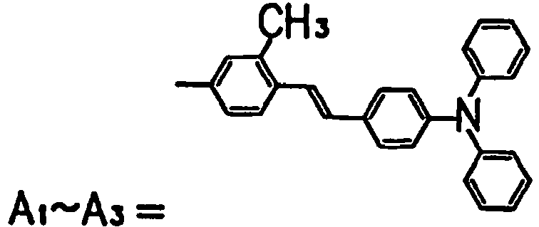
[Table I-3] 13 
14 
15 
16 
17 
18 
[Table I-4] 19 
20 
21 
22 
23 
- Table I-5 shows examples of the compound shown by the general formula (A-III), which by no means limit the compound.
[Table I-5] 24 
25 
26 
27 
- Table I-6 shows examples of the compound shown by the general formula (A-VI), which by no means limit the compound.
[Table I-6] 28 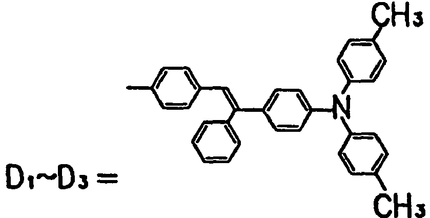
29 
30 
- Tables II -1 to II -6 show examples of the compound shown by the general formula (B-I), which by no means limit the compound.
[Table II-1] 1 
2 
3 
4 
5 
6 
[Table II -2] 7 
8 
9 
10 
11 
12 
[Table II -3] 13 
14 
15 
16 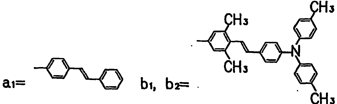
17 
18 
[Table II -4] 19 
20 
21 
22 
23 
24 
[Table II -5] 25 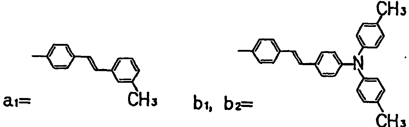
26 
27 
28 
29 
30 
[Table II -6] 31 
32 
33 
34 
35 
36 
- When the organic EL device of the present invention has the first hole transport layer of anode side containing the compound shown by the general formula (A-I), (A-III), (A-VI) or (B-I), and the second hole transport layer of light-emitting layer side containing an aromatic tertiary amine, the aromatic tertiary amine can be a known one. For example, those disclosed by Japanese Patent Publication No.
HEI 6-32307 HEI 5-234681 HEI 7-110940 HEI 5-239455 HEI 6-312982 - When the organic EL device of the present invention has an anode interface layer in contact with the anode, the anode interface layer may include a known compound. For example, a porphyrin-based compound disclosed by Japanese Patent Publication No.
SHO 64-7635 - A known organic fluorescent agent may be used for the EL light-emitting material. For example, those agents useful for the present invention include an anthracene-based compound, to begin with, metal complex of 8-quinolinol (Japanese Patent Laid-Open No.
SHO 59-194393 HEI 2-247278 HEI 5-17765 SHO 63-264692 HEI 5-70773 - Any layer for the present invention, except that containing the compound shown by the general formula (A-I), (A-III), (A-VI) or (B-I), may have any known composition. The electron transport region may be dispensed with. The materials for the anode and cathode may be selected from known ones.
- The present invention is described more concretely by Examples.

- N,N-dimethylformamide and 3,3',3''-trimethyltriphenylamine (shown by the formula (i)) were put in an ice-cooled three-necked flask equipped with a drop funnel, a nitrogen gas leading pipe and a reflux condenser, and stirred in a nitrogen atmosphere, to which phosphorus oxychloride was slowly added dropwise by the drop funnel. On completion of the addition, the temperature of the mixture was raised upto 80° C slowly and kept 80° C for 10 hours with stirring. After on completion of the reactions water was added thereto, the mixture was stirred for 15 min. The mixture was purified by the common method, to obtain 3,3',3''-trimethyl-4,4',4''-triformyltriphenylamine (shown by the formula (ii)).

- 4-chloromethyl-4',4''-dimethyltriphenylamine (shown by the formula (iii)) and triethyl phosphite were put in a three-necked flask equipped with a reflux condenser, to which toluene was added and heated with stirring for 8 hours under reflux. The mixture was purified by the common method, to obtain 4-(4',4"-dimethyldiphenylamino)benzyl diethyl phosphonate (shown by the formula (iv)).

- 3,3',3"-trimethyl-4,4',4"-triformyltriphenylamine (shown by the formula (ii)) was reacted with 4-(4',4''-dimethyldiphenylamino)benzyl diethyl phosphonate (shown by the formula (iv))in a solution of N,N-dimethylformamide suspended with hydrogenated sodium at 40°C for 40 hours. The mixture was purified by common method, to obtain 3,3',3"-trimethyl-4,4',4"-tris(4-(N,N-ditolylamino)styryl)triphenylamine (shown by the formula (v)).

- 3-bromobenzyl chloride shown by the formula (vi) and triethyl phosphite were put in a three-necked flask equipped with a reflux condenser, to which toluene was added and heated with stirring for 8 hours under reflux. The mixture was purified by common method, to obtain diethyl 3-bromobenzylphosphonate shown by the formula (vii).
- Diethyl 3-bromobenzylphosphonate shown by the formula (vii) was reacted with 4-formyltriphenylamine shown by the formula (viii) in a solution of N,N-dimethylformamide suspended with hydrogenated sodium at 40°C for 40 hours. The mixture was purified by the common method, to obtain 4-(3-bromostyryl)triphenylamine shown by the formula (ix).

- 4-(3-bromostyryl)triphenylamine (shown by the formula (ix)) and tetrahydrofuran were put in a three-necked flask equipped with a drop funnel and dryer tube, and stirred. The mixture was cooled to -78°C, to which a hexane solution of butyl lithium was added dropwise by a drop funnel. The temperature of the mixture was kept at -78°C for 1 hour and then raised upto -20°C with stirring. A toluene solution of nitrogen chloride was slowly added dropwise by a drop funnel. On completion of the addition, it was further stirred for two hours. The mixture was purified by common method, to obtain 3,3',3"-tris-(4-diphenylaminostyryl)triphenylamine (shown by the formula (x)).
- Referring to
Fig. 2(a) , aglass substrate 11 was coated with a thin film of ITO (indium tin oxide) as theanode 12, having a resistivity of 20 Ω/□, by sputtering, the compound 1 shown by Table I-1 to a thickness of 50 nm as thehole transport layer 13 by resistance heating vacuum deposition, tris-(8-hydroxyquinolinol) aluminum (compound (a)) to a thickness of 60 nm as the light-emittinglayer 14 also by resistance heating vacuum deposition, and finally MgAg (deposition rate ratio; 10:1) to a thickness of 150 nm as thecathode 16 also by resistance heating vacuum deposition, in this order.
- Very bright green color planar-emission was performed from the light-emitting layer of tris-(8-hydroxyquinolinol) aluminum. Brightness of the light was 203 cd/m2 initially at a constant current density of 10 mA/cm2 in a dried nitrogen atmosphere, and 147 cd/m2 after 1000 hours drive, by which is meant that this organic EL device of the present invention is more durable than those prepared by Comparative Examples 1 and 2.
- The same procedure as used for Example 1 was repeated, except that the material applied to the hole transport layer was replaced by the compound shown by Table I-7, to prepare the organic EL devices. They emitted very bright green color emission from the light-emitting layers of tris-(8-hydroxyquinolinol) aluminum. Brightness of the emitted light, initial and after 1000 hours drive, is given in Table I-7 for each device, at a constant current density of 10 mA/cm2 in a dried nitrogen atmosphere.
Table I-7 Examples Hole transport layer Initial brightness (cd/m2) Brightness after 1000 hours drive (cd/m2) 2 Compound 10 shown by Table I-2 221 150 3 Compound 16 shown by Table I-3216 179 4 Compound 24 shown by Table I-5 205 151 5 Compound 27 shown by Table I-5 210 161 6 Compound 28 shown by Table I-6 237 177 - Referring to
Fig. 2(b) , aglass substrate 11 was coated with a thin film of ITO as theanode 12, having a resistivity of 20 Ω / □, by sputtering, the compound 1 shown by Table I-1 to a thickness of 40 nm as the firsthole transport layer 13a by resistance heating vacuum deposition, compound (b) to a thickness of 20 nm as the secondhole transport layer 13b also by resistance heating vacuum deposition, tris-(8-hydroxyquinolinol) aluminum (compound (a)) to a thickness of 50 nm as the light-emittinglayer 14 also by resistance heating vacuum deposition, and finally MgAg (deposition rate ratio; 10:1) to a thickness of 150 nm as thecathode 16 also by resistance heating vacuum deposition.
- Very bright green color planar-emission was performed from the light-emitting layer of tris-(8-hydroxyquinolinol) aluminum. Brightness of the light was 273 cd/m2 initially at a constant current density of 10 mA/cm2 in a dried nitrogen atmosphere, and 225 cd/m2 after 1000 hours drive.
- The same procedure as used for Example 7 was repeated, except that the material applied to the first hole transport layer was replaced by the compound shown by Table I-8, to prepare the organic EL devices. They emitted very bright green color emission from the light-emitting layers of tris-(8-hydroxyquinolinol) aluminum. Brightness of the emitted light, initial and after 1000 hours drive, is given in Table I-8 for each device, at a constant current density of 10 mA/cm2 in a dried nitrogen atmosphere.
Table I-8 Examples First hole transport layer Initial brightness (cd/m2) Brightness after 1000 hours drive (cd/m2) 8 Compound 10 shown by Table I-2 291 232 9 Compound 16 shown by Table I-3253 199 10 Compound 24 shown by Table I-5 256 194 11 Compound 27 shown by Table I-5 280 241 12 Compound 28 shown by Table I-6 266 217 - Referring to
Fig. 2(a) , aglass substrate 11 was coated with a thin film of ITO as theanode 12, having a resistivity of 20 Ω / □ , by sputtering. Theanode 12 was coated with a solution, which was a mixture of the compound 1 of Table I-1 and polycarbonate (Mitubishi Chemical, Z200) (1:1 by weight) dissolved in tetrahydrofuran at 1.5 wt.%, by dip coating to a thickness of 50 nm, and dried at 80°C for 1 hour, to form thehole transport layer 13. It was then coated with tris-(8-hydroxyquinolinol) aluminum (compound (a)) to a thickness of 50 nm as the light-emittinglayer 14 by resistance heating vacuum deposition, and finally MgAg (deposition rate ratio; 10:1) to a thickness of 150 nm as thecathode 16 also by resistance heating vacuum deposition. - Very bright green color planar-emission was performed from the light-emitting layer of tris-(8-hydroxyquinolinol) aluminum. Brightness of the light was 212 cd/m2 initially at a constant current density of 10 mA/cm2 in a dried nitrogen atmosphere, and 180 cd/m2 after 1000 hours drive.
- Referring to
Fig. 2(a) , aglass substrate 11 was coated with a thin film of ITO as theanode 12, having a resistivity of 20 Ω / □, by sputtering. Theanode 12 was coated with the compound 1 of Table I-1 and compound (b) by resistance heating vacuum deposition to a thickness of 50 nm (codeposition at a rate ratio of 7:3), to form thehole transport layer 13. It was then coated with tris-(8-hydroxyquinolinol) aluminum (compound (a)) to a thickness of 50 nm as the light-emittinglayer 14 also by resistance heating vacuum deposition, and finally MgAg (deposition rate ratio; 10:1) to a thickness of 150 nm as thecathode 16 also by resistance heating vacuum deposition. - Very bright green color planar-emission was performed from the light-emitting layer of tris-(8-hydroxyquinolinol) aluminum. Brightness of the light was 276 cd/m2 initially at a constant current density of 10 mA/cm2 in a dried nitrogen atmosphere, and 212 cd/m2 after 1000 hours drive.
- Referring to
Fig. 1(a) , aglass substrate 11 was coated with a thin film of ITO (indium tin oxide) as theanode 12, having a resistivity of 20 Ω / □, by sputtering, the compound 1 of Table I-1 to a thickness of 50 nm as thehole transport layer 13 by resistance heating vacuum deposition, tris-(8-hydroxyquinolinol) aluminum (compound (a)) and DCM (compound (c)) to a thickness of 30 nm as the light-emittinglayer 14 also by resistance heating vacuum deposition (codeposition at a rate ratio of 100:2), tris-(8-hydroxyquinolinol) aluminum to a thickness of 30 nm as theelectron transport layer 15 also by resistance heating vacuum deposition, and finally MgAg (deposition rate ratio: 10:1) to a thickness of 150 nm as thecathode 16 also by resistance heating vacuum deposition, in this order.
- Very bright orange color planar-emission was performed from the light-emitting layer of DCM. Brightness of the light was 479 cd/m2 initially at a constant current density of 10 mA/cm2 in a dried nitrogen atmosphere, and 387 cd/m2 after 1000 hours drive.
- Referring to
Fig. 4 , aglass substrate 11 was coated with a thin film of ITO (indium tin oxide) as theanode 12, having a resistivity of 20 Ω / □ , by sputtering, copper phthalocyanine (compound (d)) to a thickness of 10 nm as theanode interface layer 17 by resistance heating vacuum deposition, the compound 1 of Table I-1 to a thickness of 50 nm as thehole transport layer 13 also by resistance heating vacuum deposition, tris-(8-hydroxyquinolinol) aluminum (compound (a)) to a thickness of 50 nm as the light-emittinglayer 14 also by resistance heating vacuum deposition, and finally MgAg (deposition rate ratio: 10:1) to a thickness of 150 nm as thecathode 16 also by resistance heating vacuum deposition, in this order. - Very bright green color planar-emission was performed from the light-emitting layer of tris-(8-hydroxyquinolinol) aluminum. Brightness of the light was 223 cd/m2 initially at a constant current density of 10 mA/cm2 in a dried nitrogen atmosphere, and 185 cd/m2 after 1000 hours drive.

- Referring to
Fig. 1(a) , aglass substrate 11 was coated with a thin film of ITO (indium tin oxide) as theanode 12, having a resistivity of 20 Ω / □, by sputtering, the compound (b) to a thickness of 50 nm as thehole transport layer 13 by resistance heating vacuum deposition, compound 1 of Table I-1 to a thickness of 50 nm as the light-emittinglayer 14 also by resistance heating vacuum deposition, t-Bu-PBD (compound (e)) to a thickness of 30 nm as theelectron transport layer 15 also by resistance heating vacuum deposition, and finally MgAg (deposition rate ratio: 10:1) to a thickness of 150 nm as thecathode 16 also by resistance heating vacuum deposition, in this order. - Very bright blue color planar-emission was performed from the light-emitting layer of the compound 1 of TableI-1. Brightness of the light was 711 cd/m2 at a voltage of 8 V, by which is meant that this device has improved brightness characteristics over the one prepared by Comparative Example 3.

- The same procedure as used for Example 17 was repeated, except that the material applied to the light-emitting layer was replaced by the compound shown by Table I-9, to prepare the organic EL devices. They emitted very bright emission from the light-emitting layers. Brightness of the emitted light at a voltage of 8 V is given in Table I-9 for each device.
Table I-9 Examples Light-emitting layer Brightness at 8 V (cd/m2) 18 Compound 10 shown by Table I-2 808 19 Compound 16 shown by Table I-3537 20 Compound 24 shown by Table I-5 726 21 Compound 27 shown by Table I-5 652 22 Compound 28 of Table I-6 616 - Referring to
Fig. 1(a) , aglass substrate 11 was coated with a thin film of ITO as theanode 12, having a resistivity of 20 Ω / □ , by sputtering, and the compound (b) to a thickness of 50 nm as thehole transport layer 13 by resistance heating vacuum deposition, in this order. Thehole transport layer 13 was coated with the compound 1 of Table I-1 and rubrene (compound (f)) to a thickness of 50 nm also by resistance heating vacuum deposition (codeposition at a rate ratio of 100:2), to form the light-emittinglayer 14. It was then coated with t-Bu-PBD (compound (e)) to a thickness of 30 nm as theelectron transport layer 15 also by resistance heating vacuum deposition, and finally MgAg (deposition rate ratio: 10:1) to a thickness of 150 nm as thecathode 16 also by resistance heating vacuum deposition, in this order. - It emitted very bright yellow color emission from the light-emitting layer of the compound (f). Brightness of the light was 1835 cd/m2 at a voltage of 8 V.


- 4-iodobenzyl chloride and triethyl phosphite were put in a three-necked flask equipped with a reflux condenser, to which toluene was added and heated with stirring for 8 hours under reflux. The mixture was purified by the common method, to obtain diethyl 4-iodobenzylphosphonate.

- Diethyl 4-iodobenzylphosphonate (shown by the formula (xii)) was reacted with 4-formyl-4',4''-dimethyltriphenylamine (shown by the formula (viii)) in a solution of N,N-dimethylformamide suspended with hydrogenated sodium at 40°C for 40 hours. The mixture was purified by the common method, to obtain 4-(4-iodostyryl)-4',4''-dimethyltriphenylamine (shown by the formula (xiv)).

- 4-styrylaniline (shown by the formula (xv)), 4-(4-iodostyryl)-4',4''-dimethyltriphenylamine (shown by the formula (xiv)), copper powder and potassium carbonate were added to nitrobenzene, and they were allowed to react with one another at 200°C for 40 hours. The mixture was purified by the common method, to obtain 4-styryl-4',4''-bis(4-(N,N-ditolylamino)styryl)triphenylamine (shown by the formula (xvi)).

- 3-bromobenzyl chloride (shown by the formula (vi)) and triethyl phosphite were put in a three-necked flask equipped with a reflux condenser, to which toluene was added and heated with stirring for 8 hours under reflux. The mixture was purified by the common method, to obtain diethyl 3-bromobenzylphosphonate (shown by the formula (vii)).

- Diethyl 3-bromobenzylphosphonate (shown by the formula (vii)) was reacted with 4-formyltriphenylamine (shown by the formula (viii)) in a solution of N,N-dimethylformamide suspended with hydrogenated sodium at 40°C for 40 hours. The mixture was purified by common method, to obtain 4-(3-bromostyryl)triphenylamine (shown by the formula (ix)).

- 4-styrylaniline (shown by the formula (xv)), 4-(3-bromostyryl)triphenylamine (shown by the formula (ix)), copper powder and potassium carbonate were added to nitrobenzene, and they were allowed to react with one another at 200°C for 40 hours. The mixture was purified by common method, to obtain 4-styryl-3',3''-bis-(4-diphenylaminostyryl)triphenylamine (shown by the formula (xvii)).
- Referring to
Fig. 2(a) , aglass substrate 11 was coated with a thin film of ITO (indium tin oxide) as theanode 12, having a resistivity of 20 Ω / □, by sputtering, the compound 1 shown by Table II -1 to a thickness of 50 nm as thehole transport layer 13 by resistance heating vacuum deposition, tris-(8-hydroxyquinolinol) aluminum (compound (a)) to a thickness of 60 nm as the light-emittinglayer 14 also by resistance heating vacuum deposition, and finally MgAg (deposition rate ratio; 10:1) to a thickness of 150 nm as thecathode 16 also by resistance heating vacuum deposition, in this order.
- Very bright green color planar-emission was performed from the light-emitting layer of tris-(8-hydroxyquinolinol) aluminum. Brightness of the light was 241 cd/m2 initially at a constant current density of 10 mA/cm2 in a dried nitrogen atmosphere, and 160 cd/m2 after 1000 hours drive, by which is meant that this organic EL device of the present invention is more durable than those prepared by Comparative Examples 1 and 2.
- The same procedure as used for Example 24 was repeated, except that the material applied to the hole transport layer was replaced by the compound shown by Table II -7, to prepare the organic EL devices. They emitted very bright green color emission from the light-emitting layers of tris-(8-hydroxyquinolinol) aluminum. Brightness of the emitted light, initial and after 1000 hours drive, is given in Table II -7 for each device, at a constant current density of 10 mA/cm2 in a dried nitrogen atmosphere.
Table II -7 Examples Hole transport layer Initial brightness (cd/m2) Brightness after 1000 hours drive (cd/m2) 25 Compound 3 shown by Table II-1 232 166 26 Compound 11 shown by Table II-2237 175 27 Compound 24 shown by Table II-4 254 192 28 Compound 32 shown by Table II-5 261 190 29 Compound 36 shown by Table II-5 225 169 - Referring to
Fig. 2(b) , aglass substrate 11 was coated with a thin film of ITO as theanode 12, having a resistivity of 20 Ω / □, by sputtering, the compound 1 of Table II-1 to a thickness of 40 nm as the firsthole transport layer 13a by resistance heating vacuum deposition, compound (b) to a thickness of 20 nm as the secondhole transport layer 13b also by resistance heating vacuum deposition, tris-(8-hydroxyquinolinol) aluminum (compound (a)) to a thickness of 50 nm as the light-emittinglayer 14 also by resistance heating vacuum deposition, and finally MgAg (deposition rate ratio: 10:1) to a thickness of 150 nm as thecathode 16 also by resistance heating vacuum deposition.
- Very bright green color planar-emission was performed from the light-emitting layer of tris-(8-hydroxyquinolinol) aluminum. Brightness of the light was 294 cd/m2 initially at a constant current density of 10 mA/cm2 in a dried nitrogen atmosphere, and 231 cd/m2 after 1000 hours drive.
- The same procedure as used for Example 30 was repeated, except that the material applied to the first hole transport layer was replaced by the compound shown by Table II -8, to prepare the organic EL devices. They emitted very bright green color emission from the light-emitting layers of tris-(8-hydroxyquinolinol) aluminum. Brightness of the emitted light, initial and after 1000 hours drive, is given in Table II -8 for each device, at a constant current density of 10 mA/cm2 in a dried nitrogen atmosphere.
Table II-8 Examples First hole transport layer Initial brightness (cd/m2) Brightness after 1000 hours drive (cd/m2) 8 Compound 3 shown by Table II-1 270 219 9 Compound 11 shown by Table II-2279 238 10 Compound 24 shown by Table II-4 299 255 11 Compound 32 shown by Table II-6 303 247 12 Compound 36 shown by Table II-6 273 231 - Referring to
Fig. 2(a) , aglass substrate 11 was coated with a thin film of ITO as theanode 12, having a resistivity of 20Ω/□, by sputtering. Theanode 12 was coated with a solution, which was a mixture of the compound 1 of Table II -1 and polycarbonate (Mitubishi Chemical, Z200) (1:1 by weight) dissolved in tetrahydrofuran at 1.5 wt.%, by dip coating to a thickness of 50 nm, and dried at 80°C for 1 hour, to form thehole transport layer 13. It was then coated with tris-(8-hydroxyquinolinol) aluminum (compound (a)) to a thickness of 50 nm as the light-emittinglayer 14 by resistance heating vacuum deposition, and finally MgAg (deposition rate ratio: 10:1) to a thickness of 150 nm as thecathode 16 also by resistance heating vacuum deposition. - Very bright green color planar-emission was performed from the light-emitting layer of tris-(8-hydroxyquinolinol) aluminum. Brightness of the light was 222 cd/m2 initially at a constant current density of 10 mA/cm2 in a dried nitrogen atmosphere, and 175 cd/m2 after 1000 hours drive.
- Referring to
Fig. 2(a) , aglass substrate 11 was coated with a thin film of ITO as theanode 12, having a resistivity of 20 Ω / Ω, by sputtering. Theanode 12 was coated with the compound 1 of Table II -1 and compound (b) by resistance heating vacuum deposition to a thickness of 50 nm (codeposition at a rate ratio of 7:3), to form thehole transport layer 13. It was then coated with tris-(8-hydroxyquinolinol) aluminum (compound (a)) to a thickness of 50 nm as the light-emittinglayer 14 also by resistance heating vacuum deposition, and finally MgAg (deposition rate ratio: 10:1) to a thickness of 150 nm as thecathode 16 also by resistance heating vacuum deposition. - Very bright green color planar-emission was performed from the light-emitting layer of tris-(8-hydroxyquinolinol) aluminum. Brightness of the light was 262 cd/m2 initially at a constant current density of 10 mA/cm2 in a dried nitrogen atmosphere, and 206 cd/m2 after 1000 hours drive.
- Referring to
Fig. 1(a) , aglass substrate 11 was coated with a thin film of ITO (indium tin oxide) as theanode 12, having a resistivity of 20 Ω / □ , by sputtering, the compound 1 shown by Table II -1 to a thickness of 50 nm as thehole transport layer 13 by resistance heating vacuum deposition, tris-(8-hydroxyquinolinol) aluminum (compound (a)) and DCM (compound (c)) to a thickness of 30 nm as the light-emittinglayer 14 also by resistance heating vacuum deposition (codeposition at a rate ratio of 100:2), tris-(8-hydroxyquinolinol) aluminum to a thickness of 30 nm as theelectron transport layer 15 also by resistance heating vacuum deposition, and finally MgAg (deposition rate ratio: 10:1) to a thickness of 150 nm as thecathode 16 also by resistance heating vacuum deposition, in this order.
- Very bright orange color planar-emission was performed from the light-emitting layer of DCM. Brightness of the light was 456 cd/m2 initially at a constant current density of 10 mA/cm2 in a dried nitrogen atmosphere, and 324 cd/m2 after 1000 hours drive.
- Referring to
Fig. 4 , aglass substrate 11 was coated with a thin film of ITO (indium tin oxide) as theanode 12, having a resistivity of 20 Ω / □, by sputtering, copper phthalocyanine (compound d) to a thickness of 10 nm as theanode interface layer 17 by resistance heating vacuum deposition, the compound 1 of Table II-1 to a thickness of 50 nm as thehole transport layer 13 also by resistance heating vacuum deposition, tris-(8-hydroxyquinolinol) aluminum (compound (a)) to a thickness of 50 nm as the light-emittinglayer 14 also by resistance heating vacuum deposition, and finally MgAg (deposition rate ratio: 10:1) to a thickness of 150 nm as thecathode 16 also by resistance heating vacuum deposition, in this order. - Very bright green color planar-emission was performed from the light-emitting layer of tris-(8-hydroxyquinolinol) aluminum. Brightness of the light was 252 cd/m2 initially at a constant current density of 10 mA/cm2 in a dried nitrogen atmosphere, and 201 cd/m2 after 1000 hours drive.
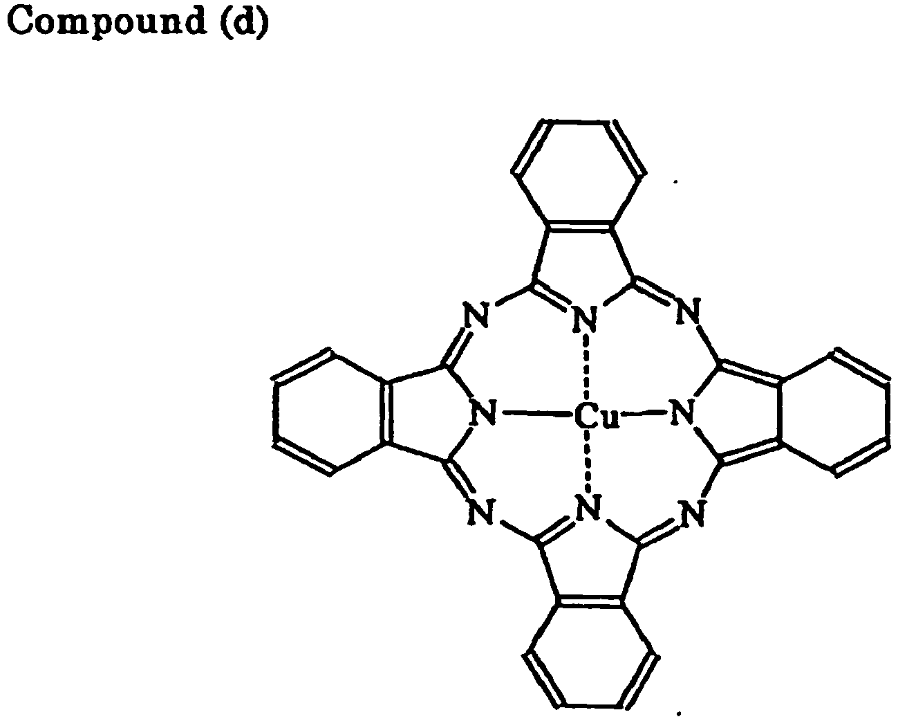
- Referring to
Fig. 1(a) , aglass substrate 11 was coated with a thin film of ITO (indium tin oxide) as theanode 12, having a resistivity of 20 Ω/□, by sputtering, the compound (b) to a thickness of 50 nm as thehole transport layer 13 by resistance heating vacuum deposition, compound 1 of Table II -1 to a thickness of 50 nm as the light-emittinglayer 14 also by resistance heating vacuum deposition, t-Bu-PBD (compound (e)) to a thickness of 30 nm as theelectron transport layer 15 also by resistance heating vacuum deposition, and finally MgAg (deposition rate ratio: 10:1) to a thickness of 150 nm as thecathode 16 also by resistance heating vacuum deposition, in this order. - Very bright blue color planar-emission was performed from the light-emitting layer of the compound 1 shown by Table II -1. Brightness of the light was 903 cd/m2 at a voltage of 8 V, by which is meant that this device has improved brightness characteristics over the one prepared by Comparative Example 3.

- The same procedure as used for Example 40 was repeated, except that the material applied to the light-emitting layer was replaced by the compound shown by Table II -9, to prepare the organic EL devices. They emitted very bright emission from the light-emitting layers. Brightness of the emitted light at a voltage of 8 V is given in Table II -9 for each device.
Table II-9 Examples Light-emitting layer Brightness at 8 V (cd/m2) 18 Compound 3 shown by Table II-1 584 19 Compound 11 shown by Table II-2885 20 Compound 24 shown by Table II-4 967 21 Compound 32 shown by Table II-6 1002 22 Compound 36 shown by Table II-6 627 - Referring to
Fig. 1(a) , aglass substrate 11 was coated with a thin film of ITO as theanode 12, having a resistivity of 20 Ω / □, by sputtering, and the compound (b) to a thickness of 50 nm as thehole transport layer 13 by resistance heating vacuum deposition, in this order. Thehole transport layer 13 was coated with the compound 1 shown by Table II -1 and rubrene (compound (f)) to a thickness of 50 nm also by resistance heating vacuum deposition (codeposition at a rate ratio of 100:2), to form the light-emittinglayer 14. It was then coated with t-Bu-PBD (compound (e)) to a thickness of 30 nm as theelectron transport layer 15 also by resistance heating vacuum deposition, and finally MgAg (deposition rate ratio: 10:1) to a thickness of 150 nm as thecathode 16 also by resistance heating vacuum deposition, in this order. - Very bright yellow color planar-emission was performed from the light-emitting layer of the compound (f). Brightness of the light was 2310 cd/m2 at a voltage of 8 V.

- A glass substrate was coated with a thin film of ITO (indium tin oxide) as the anode, having a resistivity of 20 Ω / □ , N,N'-diphenyl-N,N'-bis(3-methylphenyl)-1,1'-biphenyl-4,4'-diamine to a thickness of 50 nm as the hole transport layer, tris-(8-hydroxyquinolinol) aluminum (compound (a)) to a thickness of 60 nm as the light-emitting layer by vacuum deposition, and finally MgAg (deposition rate ratio: 10:1) to a thickness of 150 nm as the cathode also by vacuum deposition, in this order.
- Very bright green color planar-emission was performed from the light-emitting layer of tris-(8-hydroxyquinolinol) aluminum. Brightness of the light was 212 cd/m2 initially at a constant current density of 10 mA/cm2 in a dried nitrogen atmosphere, but declined to 51 cd/m2 after 630 hours drive, at which it was broken.
- A glass substrate was coated with a thin film of ITO (indium tin oxide) as the anode, having a resistivity of 20 Ω / □ , by sputtering, the compound (g) to a thickness of 50 nm as the hole transport layer by resistance heating vacuum deposition, tris-(8-hydroxyquinolinol) aluminum (compound (a)) to a thickness of 60 nm as the light-emitting layer also by resistance heating vacuum deposition, and finally MgAg (deposition rate ratio: 10:1) to a thickness of 150 nm as the cathode also by resistance heating vacuum deposition, in this order.

- Very bright green color planar-emission was performed from the light-emitting layer of tris-(8-hydroxyquinolinol) aluminum. Brightness of the light was 223 cd/m2 initially at a constant current density of 10 mA/cm2 in a dried nitrogen atmosphere, and 125 cd/m2 after 1000 hours drive.
- A glass substrate was coated with a thin film of ITO (indium tin oxide) as the anode, having a resistivity of 20 Ω / □ , by sputtering, the compound (b) to a thickness of 50 nm as the hole transport layer by resistance heating vacuum deposition, compound (g) to a thickness of 50 nm as the light-emitting layer also by resistance heating vacuum deposition, t-Bu-PBD (compound (e)) to a thickness of 30 nm as the electron transport layer also by resistance heating vacuum deposition, and finally MgAg (deposition rate ratio: 10:1) to a thickness of 150 nm as the cathode also by resistance heating vacuum deposition, in this order.
- Blue color plane-emission was performed from the light-emitting layer of the compound g. Brightness of the light was 184 cd/m2 at a voltage of 8 V.
- As described above, the present invention provides a durable, organic EL device emitting light of high brightness. Therefore, the present invention can provide an excellent EL material and EL device for full-color EL displays.

Claims (6)
- An organic electroluminescence material, characterized by(i) containing a compound shown by the following general formula (A-I)

 wherein, at least one of Z1 to Z4 and Z7 to Z10 are independently, each a halogen atom or hydroxyl, amino or substituted amino, nitro, cyano, alkyl or substituted alkyl, alkenyl or substituted alkenyl except styryl, cycloalkyl or substituted cycloalkyl, alkoxy or substituted alkoxy, aromatic hydrocarbon or substituted aromatic hydrocarbon, aromatic heterocyclic or substituted aromatic heterocyclic, aralkyl or substituted aralkyl, aryloxy or substituted aryloxy, alkoxy carbonyl or substituted alkoxy carbonyl or carboxyl group, and the others being a hydrogen atom;Z1 and Z2, Z3 and Z4 and Z7 to Z10 may from a ring by two adjacent atoms or groups;Z5 and Z6 are independently, each a hydrogen atom or alkyl or substituted alkyl, aromatic hydrocarbon or substituted aromatic hydrocarbon, or aromatic heterocyclic or substituted aromatic heterocyclic group; andAr1 and Ar2 are independently each an aryl group which may be substituted; or(ii) containing a compound shown by the following general formula (A-III):
 wherein, at least one of Y1 to Y5 is a substituent shown by the general formula (A-V), the others being independently each a hydrogen atom, a halogen atom, or hydroxyl, amino or substituted amino, nitro, cyano, alkyl or substituted alkyl, alkenyl or substituted alkenyl other than styryl, cycloalkyl or substituted cycloalkyl, alkoxy or substituted alkoxy, aromatic hydrocarbon or substituted aromatic hydrocarbon, aromatic heterocyclic or substituted aromatic heterocyclic, aralkyl or substituted aralkyl, aryloxy or substituted aryloxy, alkoxy carbonyl or substituted alkoxy carbonyl or carboxyl group; andY1 to Y5 may from a ring by two adjacent atoms or groups;
 wherein, at least one of Y6 to Y10 is a substituent shown by the formula -NAr1Ar2, the others being independently each a hydrogen atom, a halogen atom or hydroxyl, amino or substituted amino, nitro, cyano, alkyl or substituted alkyl, alkenyl or substituted alkenyl other than styryl, cycloalkyl or substituted cycloalkyl, alkoxy or substituted alkoxy, aromatic hydrocarbon or substituted aromatic hydrocarbon, aromatic heterocyclic or substituted aromatic heterocyclic, aralkyl or substituted aralkyl, aryloxy or substituted aryloxy, alkoxy carbonyl or substituted alkoxy carbonyl or carboxyl group;Y6 to Y10 may form a ring by two adjacent atoms or groups;Ar1 and Ar2 are independently each an aryl group which may be substituted; andY11 and Y12 are independently, each a hydrogen atom or alkyl or substituted alkyl, aromatic hydrocarbon or substituted aromatic hydrocarbon, aromatic heterocyclic or substituted aromatic heterocyclic;excluding the compounds where the substituent shown in general Formula (A-V) is at the site of Y3 and, at the same time, the substituent shown by formula -NAr1Ar2 is at the site of Y8; or(iii) containing a compound shown by the following general formula (A-VI)
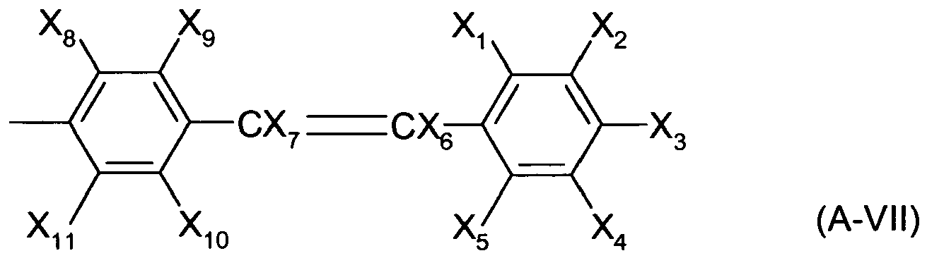 wherein, at least one of X1 to X5 is a substituent shown by the formula -NAr1Ar2, the others being independently each a hydrogen atom, a halogen atom or hydroxyl, amino or substituted amino, nitro, cyano, alkyl or substituted alkyl, alkenyl or substituted alkenyl other than styryl, cycloalkyl or substituted cycloalkyl, alkoxy or substituted alkoxy, aromatic hydrocarbon or substituted aromatic hydrocarbon, aromatic heterocyclic or substituted aromatic heterocyclic, aralkyl or substituted aralkyl, aryloxy or substituted aryloxy, alkoxy carbonyl or substituted alkoxy carbonyl or carboxyl group;X1 to X5 may from a ring by two adjacent atoms or groups;Ar1 and Ar2 are independently, each an aryl group which may be substituted;X6 and X7 are independently, each an alkyl group having 2 or more carbons, aromatic hydrocarbon group or aromatic heterocyclic group, all of which may be substituted; andX8 to X11 are independently each a hydrogen atom, a halogen atom or hydroxyl, amino or substituted amino, nitro, cyano, alkyl or substituted alkyl, alkenyl or substituted alkenyl except styryl, cycloalkyl or substituted cycloalkyl, alkoxy or substituted alkoxy, aromatic hydrocarbon or substituted aromatic hydrocarbon, aromatic heterocyclic or substituted aromatic heterocyclic, aralkyl or substituted aralkyl, aryloxy or substituted aryloxy, alkoxy carbonyl or substituted alkoxy carbonyl or carboxyl group and X8 to X11 may from a ring by two adjacent atoms or groups; or(iv) containing a compound shown by the following general formula (B-I)
 wherein, y1 to y5 are independently, each a hydrogen atom, a halogen atom or hydroxyl, nitro, cyano, alkyl or substituted alkyl, alkenyl or substituted alkenyl except styryl, cycloalkyl or substituted cycloalkyl, alkoxy or substituted alkoxy, aromatic hydrocarbon or substituted aromatic hydrocarbon, aromatic heterocyclic or substituted aromatic heterocyclic, aralkyl or substituted aralkyl, aryloxy or substituted aryloxy, alkoxy carbonyl or substituted alkoxy carbonyl or carboxyl group; andy1 to y5 may form a ring by two adjacent atoms or groups;y6 and y7 are independently, each a hydrogen atom, alkyl or substituted alkyl, aromatic hydrocarbon or substituted aromatic hydrocarbon, aromatic heterocyclic or substituted aromatic heterocyclic group;
 wherein, at least one of Z1 to Z5 is a substituent shown by the formula -NAr1Ar2, the others being independently, each a hydrogen atom, a halogen atom or hydroxyl, nitro, cyano, alkyl or substituted alkyl alkenyl or substituted alkenyl except styryl, cycloalkyl or substituted cycloalkyl, alkoxy or substituted alkoxy, aromatic hydrocarbon or substituted aromatic hydrocarbon, aromatic heterocyclic or substituted aromatic heterocyclic, aralkyl or substituted aralkyl, aryloxy or substituted aryloxy, alkoxy carbonyl or substituted alkoxy carbonyl or carboxyl group; andZ1 to Z4 may form a ring by two adjacent atoms or groups;Ar1 and Ar2 are independently, each an aryl group which may be substituted; andZ6 and Z7 are independently, each a hydrogen atom or alkyl or substituted alkyl, aromatic hydrocarbon or substituted aromatic hydrocarbon, or aromatic heterocyclic or substituted aromatic heterocyclic group.
 - An organic electroluminescence device comprising one or more layers of organic thin films put between the anode and cathode, wherein at least one of said layers is composed of at least one of the organic electroluminescence materials according to claim 1.
- The organic electroluminescence device of claim 2, wherein at least one of said layers has a thickness of 2 to 500 nm.
- The organic electroluminescence device of any of claims 2 or 3, wherein the layers include a hole transport layer, a light-emitting layer and an electron transport layer and wherein one of these layers is composed of at least one of the organic electroluminescence materials according to claim 1.
- The organic electroluminescence device of claim 4, wherein said light-emitting layer is doped with an organic luminescent agent as a dopant.
- A composition comprising the organic electroluminescence material of claim 1 dispersed in a polymer binder.
Applications Claiming Priority (4)
| Application Number | Priority Date | Filing Date | Title |
|---|---|---|---|
| JP21833699 | 1999-08-02 | ||
| JP21833699A JP3548840B2 (en) | 1999-08-02 | 1999-08-02 | Organic electroluminescent material and electroluminescent device using the same |
| JP21833799A JP3501279B2 (en) | 1999-08-02 | 1999-08-02 | ORGANIC ELECTROLUMINESCENT MATERIAL AND ELECTROLUMINESCENT DEVICE USING THE MATERIAL |
| JP21833799 | 1999-08-02 |
Publications (3)
| Publication Number | Publication Date |
|---|---|
| EP1074601A2 EP1074601A2 (en) | 2001-02-07 |
| EP1074601A3 EP1074601A3 (en) | 2004-12-01 |
| EP1074601B1 true EP1074601B1 (en) | 2014-11-05 |
Family
ID=26522511
Family Applications (1)
| Application Number | Title | Priority Date | Filing Date |
|---|---|---|---|
| EP00116726.1A Expired - Lifetime EP1074601B1 (en) | 1999-08-02 | 2000-08-02 | Organic electroluminescent material and electroluminescent device using the same |
Country Status (4)
| Country | Link |
|---|---|
| US (2) | US7201976B2 (en) |
| EP (1) | EP1074601B1 (en) |
| KR (1) | KR100364951B1 (en) |
| TW (1) | TW562848B (en) |
Families Citing this family (6)
| Publication number | Priority date | Publication date | Assignee | Title |
|---|---|---|---|---|
| JP4161262B2 (en) * | 2002-06-26 | 2008-10-08 | ソニー株式会社 | ORGANIC ELECTROLUMINESCENT ELEMENT AND LIGHT EMITTING OR DISPLAY DEVICE USING THE SAME |
| TW200613515A (en) * | 2004-06-26 | 2006-05-01 | Merck Patent Gmbh | Compounds for organic electronic devices |
| DE102004031000A1 (en) * | 2004-06-26 | 2006-01-12 | Covion Organic Semiconductors Gmbh | Organic electroluminescent devices |
| DE102005058543A1 (en) * | 2005-12-08 | 2007-06-14 | Merck Patent Gmbh | Organic electroluminescent devices |
| DE102005058557A1 (en) * | 2005-12-08 | 2007-06-14 | Merck Patent Gmbh | Organic electroluminescent device |
| JP7147133B2 (en) | 2017-06-30 | 2022-10-05 | ブラザー工業株式会社 | liquid containment unit |
Family Cites Families (11)
| Publication number | Priority date | Publication date | Assignee | Title |
|---|---|---|---|---|
| JP2884353B2 (en) | 1989-09-08 | 1999-04-19 | コニカ株式会社 | Electrophotographic photoreceptor |
| JP3099529B2 (en) * | 1992-07-13 | 2000-10-16 | 富士電機株式会社 | Organic thin film light emitting device |
| JP3303200B2 (en) | 1993-06-15 | 2002-07-15 | 株式会社リコー | Electrophotographic photoreceptor |
| JP3540008B2 (en) | 1993-06-15 | 2004-07-07 | 株式会社リコー | Diamine compound having pyrenyl group and method for producing the same |
| JPH0720644A (en) | 1993-06-30 | 1995-01-24 | Konica Corp | Organic electrophotographic photoreceptor and production thereof |
| JP2940502B2 (en) | 1996-02-28 | 1999-08-25 | 日本電気株式会社 | Electrophotographic photoreceptor |
| JPH09304952A (en) | 1996-05-10 | 1997-11-28 | Fuji Electric Co Ltd | Electrophotographic photoreceptor |
| JP3016363B2 (en) | 1996-11-11 | 2000-03-06 | 日本電気株式会社 | Organic thin film EL device |
| JP3503403B2 (en) * | 1997-03-17 | 2004-03-08 | 東洋インキ製造株式会社 | Light emitting material for organic electroluminescent device and organic electroluminescent device using the same |
| JPH1174079A (en) * | 1997-06-20 | 1999-03-16 | Nec Corp | Organic electroluminescence device |
| JP3864516B2 (en) | 1997-09-29 | 2007-01-10 | 東洋インキ製造株式会社 | Organic electroluminescent device material and organic electroluminescent device using the same |
-
2000
- 2000-08-02 TW TW089115559A patent/TW562848B/en not_active IP Right Cessation
- 2000-08-02 KR KR1020000044776A patent/KR100364951B1/en not_active Expired - Fee Related
- 2000-08-02 EP EP00116726.1A patent/EP1074601B1/en not_active Expired - Lifetime
-
2003
- 2003-05-30 US US10/448,704 patent/US7201976B2/en not_active Expired - Lifetime
-
2006
- 2006-08-02 US US11/461,908 patent/US20060263639A1/en not_active Abandoned
Also Published As
| Publication number | Publication date |
|---|---|
| US20040018387A1 (en) | 2004-01-29 |
| KR100364951B1 (en) | 2002-12-16 |
| TW562848B (en) | 2003-11-21 |
| US20060263639A1 (en) | 2006-11-23 |
| KR20010021180A (en) | 2001-03-15 |
| EP1074601A3 (en) | 2004-12-01 |
| US7201976B2 (en) | 2007-04-10 |
| EP1074601A2 (en) | 2001-02-07 |
Similar Documents
| Publication | Publication Date | Title |
|---|---|---|
| US6582837B1 (en) | Organic electroluminescence device | |
| JP3424812B2 (en) | Organic electroluminescence device | |
| US20050227111A1 (en) | Organic electroluminescence device | |
| US6329083B1 (en) | Organic electroluminescent device containing a benzoperylene compound | |
| JPH1174079A (en) | Organic electroluminescence device | |
| US6746784B2 (en) | Organic electroluminescent device | |
| JP3092584B2 (en) | Organic electroluminescence device | |
| US6322908B1 (en) | Organic electroluminescent device | |
| US20010006741A1 (en) | Organic electroluminescent device | |
| JPH11228951A (en) | Organic electroluminescent element | |
| US6682831B2 (en) | Organic electroluminescent device | |
| US8349472B2 (en) | Organic electroluminescence device | |
| JP3961200B2 (en) | Organic electroluminescence device | |
| US7201976B2 (en) | Organic electroluminescence material and electroluminescence device using the same | |
| JPH11144870A (en) | Organic electroluminescent element | |
| JP2882403B1 (en) | Organic electroluminescence device material and organic electroluminescence device using the same | |
| JP3548840B2 (en) | Organic electroluminescent material and electroluminescent device using the same | |
| US20020168543A1 (en) | Organic electroluminscent device | |
| JP3005980B2 (en) | Organic electroluminescent device | |
| JP4139055B2 (en) | Organic electroluminescence device | |
| JP3501279B2 (en) | ORGANIC ELECTROLUMINESCENT MATERIAL AND ELECTROLUMINESCENT DEVICE USING THE MATERIAL | |
| JP3625764B2 (en) | Organic electroluminescence device | |
| JP2001196180A (en) | Organic electroluminescent element |
Legal Events
| Date | Code | Title | Description |
|---|---|---|---|
| PUAI | Public reference made under article 153(3) epc to a published international application that has entered the european phase |
Free format text: ORIGINAL CODE: 0009012 |
|
| AK | Designated contracting states |
Kind code of ref document: A2 Designated state(s): AT BE CH CY DE DK ES FI FR GB GR IE IT LI LU MC NL PT SE |
|
| AX | Request for extension of the european patent |
Free format text: AL;LT;LV;MK;RO;SI |
|
| RAP1 | Party data changed (applicant data changed or rights of an application transferred) |
Owner name: SAMSUNG SDI CO., LTD. |
|
| PUAL | Search report despatched |
Free format text: ORIGINAL CODE: 0009013 |
|
| AK | Designated contracting states |
Kind code of ref document: A3 Designated state(s): AT BE CH CY DE DK ES FI FR GB GR IE IT LI LU MC NL PT SE |
|
| AX | Request for extension of the european patent |
Extension state: AL LT LV MK RO SI |
|
| RIC1 | Information provided on ipc code assigned before grant |
Ipc: 7H 01L 51/30 A |
|
| 17P | Request for examination filed |
Effective date: 20050124 |
|
| AKX | Designation fees paid |
Designated state(s): AT BE CH CY DE DK ES FI FR GB GR IE IT LI LU MC NL PT SE |
|
| 17Q | First examination report despatched |
Effective date: 20060919 |
|
| RAP1 | Party data changed (applicant data changed or rights of an application transferred) |
Owner name: SAMSUNG MOBILE DISPLAY CO., LTD. |
|
| RAP1 | Party data changed (applicant data changed or rights of an application transferred) |
Owner name: SAMSUNG DISPLAY CO., LTD. |
|
| GRAP | Despatch of communication of intention to grant a patent |
Free format text: ORIGINAL CODE: EPIDOSNIGR1 |
|
| RIC1 | Information provided on ipc code assigned before grant |
Ipc: H01L 51/30 20060101AFI20140120BHEP Ipc: H01L 51/50 20060101ALI20140120BHEP Ipc: C07C 211/56 20060101ALI20140120BHEP Ipc: C07C 211/57 20060101ALI20140120BHEP Ipc: C07C 211/54 20060101ALI20140120BHEP Ipc: H01L 51/00 20060101ALI20140120BHEP Ipc: C09K 11/06 20060101ALI20140120BHEP Ipc: C07C 217/80 20060101ALI20140120BHEP Ipc: C07C 217/92 20060101ALI20140120BHEP Ipc: H05B 33/14 20060101ALI20140120BHEP |
|
| INTG | Intention to grant announced |
Effective date: 20140212 |
|
| GRAS | Grant fee paid |
Free format text: ORIGINAL CODE: EPIDOSNIGR3 |
|
| GRAP | Despatch of communication of intention to grant a patent |
Free format text: ORIGINAL CODE: EPIDOSNIGR1 |
|
| INTG | Intention to grant announced |
Effective date: 20140702 |
|
| GRAS | Grant fee paid |
Free format text: ORIGINAL CODE: EPIDOSNIGR3 |
|
| GRAA | (expected) grant |
Free format text: ORIGINAL CODE: 0009210 |
|
| AK | Designated contracting states |
Kind code of ref document: B1 Designated state(s): AT BE CH CY DE DK ES FI FR GB GR IE IT LI LU MC NL PT SE |
|
| REG | Reference to a national code |
Ref country code: GB Ref legal event code: FG4D |
|
| REG | Reference to a national code |
Ref country code: CH Ref legal event code: EP |
|
| REG | Reference to a national code |
Ref country code: AT Ref legal event code: REF Ref document number: 695006 Country of ref document: AT Kind code of ref document: T Effective date: 20141115 |
|
| REG | Reference to a national code |
Ref country code: IE Ref legal event code: FG4D |
|
| REG | Reference to a national code |
Ref country code: DE Ref legal event code: R096 Ref document number: 60048767 Country of ref document: DE Effective date: 20141218 |
|
| REG | Reference to a national code |
Ref country code: AT Ref legal event code: MK05 Ref document number: 695006 Country of ref document: AT Kind code of ref document: T Effective date: 20141105 |
|
| REG | Reference to a national code |
Ref country code: NL Ref legal event code: VDEP Effective date: 20141105 |
|
| PG25 | Lapsed in a contracting state [announced via postgrant information from national office to epo] |
Ref country code: ES Free format text: LAPSE BECAUSE OF FAILURE TO SUBMIT A TRANSLATION OF THE DESCRIPTION OR TO PAY THE FEE WITHIN THE PRESCRIBED TIME-LIMIT Effective date: 20141105 Ref country code: PT Free format text: LAPSE BECAUSE OF FAILURE TO SUBMIT A TRANSLATION OF THE DESCRIPTION OR TO PAY THE FEE WITHIN THE PRESCRIBED TIME-LIMIT Effective date: 20150305 Ref country code: FI Free format text: LAPSE BECAUSE OF FAILURE TO SUBMIT A TRANSLATION OF THE DESCRIPTION OR TO PAY THE FEE WITHIN THE PRESCRIBED TIME-LIMIT Effective date: 20141105 Ref country code: NL Free format text: LAPSE BECAUSE OF FAILURE TO SUBMIT A TRANSLATION OF THE DESCRIPTION OR TO PAY THE FEE WITHIN THE PRESCRIBED TIME-LIMIT Effective date: 20141105 |
|
| PG25 | Lapsed in a contracting state [announced via postgrant information from national office to epo] |
Ref country code: SE Free format text: LAPSE BECAUSE OF FAILURE TO SUBMIT A TRANSLATION OF THE DESCRIPTION OR TO PAY THE FEE WITHIN THE PRESCRIBED TIME-LIMIT Effective date: 20141105 Ref country code: AT Free format text: LAPSE BECAUSE OF FAILURE TO SUBMIT A TRANSLATION OF THE DESCRIPTION OR TO PAY THE FEE WITHIN THE PRESCRIBED TIME-LIMIT Effective date: 20141105 Ref country code: GR Free format text: LAPSE BECAUSE OF FAILURE TO SUBMIT A TRANSLATION OF THE DESCRIPTION OR TO PAY THE FEE WITHIN THE PRESCRIBED TIME-LIMIT Effective date: 20150206 Ref country code: CY Free format text: LAPSE BECAUSE OF FAILURE TO SUBMIT A TRANSLATION OF THE DESCRIPTION OR TO PAY THE FEE WITHIN THE PRESCRIBED TIME-LIMIT Effective date: 20141105 |
|
| PG25 | Lapsed in a contracting state [announced via postgrant information from national office to epo] |
Ref country code: DK Free format text: LAPSE BECAUSE OF FAILURE TO SUBMIT A TRANSLATION OF THE DESCRIPTION OR TO PAY THE FEE WITHIN THE PRESCRIBED TIME-LIMIT Effective date: 20141105 |
|
| REG | Reference to a national code |
Ref country code: DE Ref legal event code: R097 Ref document number: 60048767 Country of ref document: DE |
|
| PLBE | No opposition filed within time limit |
Free format text: ORIGINAL CODE: 0009261 |
|
| STAA | Information on the status of an ep patent application or granted ep patent |
Free format text: STATUS: NO OPPOSITION FILED WITHIN TIME LIMIT |
|
| RAP2 | Party data changed (patent owner data changed or rights of a patent transferred) |
Owner name: SAMSUNG DISPLAY CO., LTD. |
|
| 26N | No opposition filed |
Effective date: 20150806 |
|
| PG25 | Lapsed in a contracting state [announced via postgrant information from national office to epo] |
Ref country code: IT Free format text: LAPSE BECAUSE OF FAILURE TO SUBMIT A TRANSLATION OF THE DESCRIPTION OR TO PAY THE FEE WITHIN THE PRESCRIBED TIME-LIMIT Effective date: 20141105 |
|
| PG25 | Lapsed in a contracting state [announced via postgrant information from national office to epo] |
Ref country code: LU Free format text: LAPSE BECAUSE OF FAILURE TO SUBMIT A TRANSLATION OF THE DESCRIPTION OR TO PAY THE FEE WITHIN THE PRESCRIBED TIME-LIMIT Effective date: 20150802 Ref country code: MC Free format text: LAPSE BECAUSE OF FAILURE TO SUBMIT A TRANSLATION OF THE DESCRIPTION OR TO PAY THE FEE WITHIN THE PRESCRIBED TIME-LIMIT Effective date: 20141105 |
|
| REG | Reference to a national code |
Ref country code: CH Ref legal event code: PL |
|
| PG25 | Lapsed in a contracting state [announced via postgrant information from national office to epo] |
Ref country code: CH Free format text: LAPSE BECAUSE OF NON-PAYMENT OF DUE FEES Effective date: 20150831 Ref country code: LI Free format text: LAPSE BECAUSE OF NON-PAYMENT OF DUE FEES Effective date: 20150831 |
|
| REG | Reference to a national code |
Ref country code: IE Ref legal event code: MM4A |
|
| REG | Reference to a national code |
Ref country code: FR Ref legal event code: PLFP Year of fee payment: 17 |
|
| PG25 | Lapsed in a contracting state [announced via postgrant information from national office to epo] |
Ref country code: IE Free format text: LAPSE BECAUSE OF NON-PAYMENT OF DUE FEES Effective date: 20150802 |
|
| REG | Reference to a national code |
Ref country code: FR Ref legal event code: PLFP Year of fee payment: 18 |
|
| PG25 | Lapsed in a contracting state [announced via postgrant information from national office to epo] |
Ref country code: BE Free format text: LAPSE BECAUSE OF FAILURE TO SUBMIT A TRANSLATION OF THE DESCRIPTION OR TO PAY THE FEE WITHIN THE PRESCRIBED TIME-LIMIT Effective date: 20141105 |
|
| REG | Reference to a national code |
Ref country code: FR Ref legal event code: PLFP Year of fee payment: 19 |
|
| PGFP | Annual fee paid to national office [announced via postgrant information from national office to epo] |
Ref country code: DE Payment date: 20180723 Year of fee payment: 19 Ref country code: FR Payment date: 20180725 Year of fee payment: 19 |
|
| PGFP | Annual fee paid to national office [announced via postgrant information from national office to epo] |
Ref country code: GB Payment date: 20180724 Year of fee payment: 19 |
|
| REG | Reference to a national code |
Ref country code: DE Ref legal event code: R119 Ref document number: 60048767 Country of ref document: DE |
|
| GBPC | Gb: european patent ceased through non-payment of renewal fee |
Effective date: 20190802 |
|
| PG25 | Lapsed in a contracting state [announced via postgrant information from national office to epo] |
Ref country code: FR Free format text: LAPSE BECAUSE OF NON-PAYMENT OF DUE FEES Effective date: 20190831 Ref country code: DE Free format text: LAPSE BECAUSE OF NON-PAYMENT OF DUE FEES Effective date: 20200303 |
|
| PG25 | Lapsed in a contracting state [announced via postgrant information from national office to epo] |
Ref country code: GB Free format text: LAPSE BECAUSE OF NON-PAYMENT OF DUE FEES Effective date: 20190802 |