EP1074503B1 - Levelling for double deck elevator car - Google Patents
Levelling for double deck elevator car Download PDFInfo
- Publication number
- EP1074503B1 EP1074503B1 EP00111810A EP00111810A EP1074503B1 EP 1074503 B1 EP1074503 B1 EP 1074503B1 EP 00111810 A EP00111810 A EP 00111810A EP 00111810 A EP00111810 A EP 00111810A EP 1074503 B1 EP1074503 B1 EP 1074503B1
- Authority
- EP
- European Patent Office
- Prior art keywords
- elevator car
- screw shaft
- double deck
- screw
- engagement unit
- Prior art date
- Legal status (The legal status is an assumption and is not a legal conclusion. Google has not performed a legal analysis and makes no representation as to the accuracy of the status listed.)
- Expired - Lifetime
Links
- 230000007246 mechanism Effects 0.000 claims description 14
- 230000005540 biological transmission Effects 0.000 claims description 12
- 239000000725 suspension Substances 0.000 claims description 12
- 239000011295 pitch Substances 0.000 claims description 7
- 238000010276 construction Methods 0.000 claims description 3
- 230000005484 gravity Effects 0.000 claims description 3
- 238000010586 diagram Methods 0.000 description 3
- 238000006073 displacement reaction Methods 0.000 description 3
- 230000008878 coupling Effects 0.000 description 2
- 238000010168 coupling process Methods 0.000 description 2
- 238000005859 coupling reaction Methods 0.000 description 2
- 230000004048 modification Effects 0.000 description 2
- 238000012986 modification Methods 0.000 description 2
- 230000009467 reduction Effects 0.000 description 2
- 230000008859 change Effects 0.000 description 1
- 239000000203 mixture Substances 0.000 description 1
- 238000005728 strengthening Methods 0.000 description 1
- 238000009423 ventilation Methods 0.000 description 1
Images




Classifications
-
- B—PERFORMING OPERATIONS; TRANSPORTING
- B66—HOISTING; LIFTING; HAULING
- B66B—ELEVATORS; ESCALATORS OR MOVING WALKWAYS
- B66B1/00—Control systems of elevators in general
-
- B—PERFORMING OPERATIONS; TRANSPORTING
- B66—HOISTING; LIFTING; HAULING
- B66B—ELEVATORS; ESCALATORS OR MOVING WALKWAYS
- B66B11/00—Main component parts of lifts in, or associated with, buildings or other structures
- B66B11/02—Cages, i.e. cars
- B66B11/0206—Car frames
- B66B11/0213—Car frames for multi-deck cars
- B66B11/022—Car frames for multi-deck cars with changeable inter-deck distances
-
- B—PERFORMING OPERATIONS; TRANSPORTING
- B66—HOISTING; LIFTING; HAULING
- B66B—ELEVATORS; ESCALATORS OR MOVING WALKWAYS
- B66B11/00—Main component parts of lifts in, or associated with, buildings or other structures
Definitions
- the present invention relates to a double deck elevator car that has two elevator cars, one above the other, and may vary the gap between the elevator cars.
- the need has intensified for elevator cars having two elevator cars provided in the vertical direction (double deck elevator cars) in order to increase transport capability in the vertical direction of ultra-high-rise buildings.
- the first floor height is often higher than that of normal floors because the first floor is an entrance hall or a lobby and the first floor is often used for ventilation, and so it is not possible to use a double deck elevator car in which the gap between the upper and lower elevator cars is fixed.
- outer frame 3 that incorporates upper and lower elevator cars 4 and 5 , is raised and lowered by hoist 2 provided above hoistway 1.
- hoist 2 provided above hoistway 1.
- One or other of elevator cars 4 and 5 is raised or lowered in relation to outer frame 3 by a drive source for motors or the like provided in this outer frame 3 (Laid-Open Patent No. Showa 48-5384).
- US-A-1914128 discloses an elevator car according to the preamble of claim 1.
- one object of the present invention is to provide a novel double deck elevator car that, being a double deck elevator car having two elevator cars, may easily and simply vary the gap between the elevator cars.
- the present invention provides an elevator car according to claim 1.
- the car itself as a whole may be lightened and made smaller by strengthening the carrier alone. Also, since the screw thread direction of the at least one first screw shaft for supporting the weight of the first elevator car and the screw thread direction of the at least one second screw shaft for supporting the weight of the second elevator car are opposite, the first elevator car and the second elevator car play the roles of mutual counterweights. Thus, the capacity of the driving mechanisms may be made smaller.
- the present invention is a double deck elevator car that has the characteristic of, at least, the first elevator car engagement unit or the second elevator car engagement unit having:
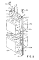
- FIG.3 to FIG.7 are drawings showing a first embodiment of a double deck elevator car according to the present invention.
- the double deck elevator car possesses first elevator car 23a and second elevator car 23b that are consecutively arranged in the vertical direction inside hoistway 1 .
- first elevator car 23a in the upper position stops at upper floor 41
- second elevator car 23b in the lower position stops at lower floor 42 .
- the double deck elevator car may vary the gap between first elevator car 23a and second elevator car 23b .
- outer frame (carrier or supporting member is sometimes used) 11 and balance weight 15 are suspended via suspension cables 16 that pass over traction sheave 13 of hoist 12 and deflector sheave 14 , and are raised and lowered by the rotational drive of hoist 12 .
- outer frame 11 and balance weight (counterweight) 15 are arranged inside hoistway 1 , while hoist 12 , having traction sheave 13 , and deflector sheave 14 are positioned in machinery room 2 provided above hoistway 1 .
- first elevator car 23a and second elevator car 23b are supported in the vertical direction, so that they are free to move, in outer frame 11 .
- Outer frame 11 has upper beam 11a that is connected via pitch springs (not shown) to the ends of suspension cables 16 , vertical beams 11b that are connected to upper beam 11a and extend perpendicularly downward, and lower beam 11c that connects the lower ends of vertical beams 11b . Furthermore, it has a pair of support beams 11d that are secured to upper beam 11a and protrude in mutually opposite directions. A drive motor (driving mechanism) 17 is supported on each of the pair of support beams 11d out of the above.
- a transmission member 19 having first screw shaft 19a that is protected by housing 18 secured to support beam 11d and second screw shaft 19b connected to this first screw shaft 19a , is provided for each drive motor 17 .
- First screw shaft 19a and second screw shaft 19b are connected via respective flanges 45a and 45b . Also, the lower end of second screw shaft 19b is supported, so that it is free to rotate, by support 20 secured to vertical beam 11b .
- first screw shafts 19a and second screw shafts 19b are formed by cutting their respective screw threads in opposite directions, and compose inverse helical relationships with each other.
- nuts 25a of car frame 22a that supports first elevator car 23a engage with first screw shafts 19a
- nuts 25b of car frame 22b that supports second elevator car 23b engage with second screw shafts 19b .
- first elevator car 23a and second elevator car 23b are respectively supported via car frames 22a and 22b by first screw shafts 19a and second screw shafts 19b.
- guidance devices 10 having guide rollers that engage with a pair of main guide rails 50 provided in hoistway 1 , are mounted at four places at the upper and lower left and right of outer frame 11 .
- Guidance of outer frame 11 is performed by guidance devices 10 engaging with main guide rails 50 .
- guidance devices 21 that engage with each vertical beam 11b of outer frame 11 , are mounted at four places at the upper and lower left and right of each of car frames 22a and 22b .
- counter-weight 15 also has guidance devices that engage with a pair of sub-guide rails (not illustrated).
- output shaft 17a of drive motor 17 which is secured to support beam 11d , is connected to first screw shaft 19a via tie shaft 26 .
- first screw shaft 19a is protected by housing 18 secured to support beam 11d , and is also supported in housing 18 via bearing 28 , so that it is free to rotate.
- flange 45b of second screw shaft 19b on which the screw thread is cut in the reverse direction to that of first screw shaft 19a , is coupled to flange 45a on the lower end of screw shaft 19a .
- the lower end of screw shaft 19b is supported via bearing 48 , so that it is free to rotate, in support 20 provided on vertical beam 11b .
- Couplers 46 are provided on each of car frame 22a of first elevator car 23a and car frame 22b of second elevator car 23b .
- first elevator car 23a and second elevator car 23b The design is that, should slight displacement occur in the horizontal direction between first elevator car 23a and second elevator car 23b and transmission members 19 , that displacement may be absorbed by couplers 46 .
- the engagement units of first elevator car 23a and second elevator car 23b are composed by couplers 46 and nuts 25a and 25b .
- outer frame 11 ascends or descends along guide rails 50 by means of suspensions cable 16 that pass over sheaves 13 and 14 .
- right-hand torques are applied to first screw shafts 19a via nuts 25a by the weight of first elevator car 23a and car frame 22a .
- left-hand torques are applied to screw shafts 19b , which are directly coupled to first screw shafts 19a , via nuts 25b by the weight of second elevator car 23b and car frame 22b .
- weights of the two elevator cars 23a and 23b and of the two car frames 22a and 22b are all applied to support beam 11c , which is secured to upper beam 11a , via first screw shafts 19a and second screw shafts 19b . Therefore, no structural problems will arise if only upper beam 11a of outer frame 11 is strengthened.
- each transmission member 19 rotates and, for example, car frame 22a , having nuts 25a that engage with first screw shafts 19a , ascends while car frame 22b , having nuts 25b that engage with second screw shafts 19b , descends.
- car frames 22a and 22b move in vertical directions guided along vertical beams 11b of outer frame 11 by guidance devices 21 .
- First elevator car 23a and second elevator car 23b move in vertical directions in accompaniment to the movements in the vertical direction of car frames 22a and 22b .
- the gap between the two car s 23a and 23b varies from h to h' and it becomes possible for each of car s 23a and 23b to arrive at floors 41 and 42 that have differing floor heights.
- first elevator car 23a and second elevator car 23b are unequal, or when it is desired to alter the movement distances of upper and lower car s 23a and 23b , these situations may be coped with by changing the pitches of first screw shafts 19a and second screw shafts 19b .
- FIG.8 and FIG.9 Next, a second embodiment of an elevator car according to the present invention will be described using FIG.8 and FIG.9 .
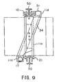
- FIG.8 and FIG.9 is one in which, in the first embodiment shown in FIG.3 to FIG.7 , reduction gears 33 are provided between each drive motor 17 and screw shafts 19a and 19b ( FIG.8 ), or only a single drive motor 17 is provided and the motive power of this drive motor 17 is transmitted to the other drive mechanism 51 via toothed belt 34 ( FIG.9 ).
- FIG.8 and FIG.9 parts that are identical to those of the first embodiment shown in FIG.3 to FIG.7 have been assigned identical reference numerals and their detailed descriptions have been omitted.
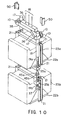
- FIG.10 a third embodiment of an elevator car according to the present invention will be described using FIG.10 .
- This embodiment provides suspension beam 35 as the carrier in place of outer frame 11 .
- parts that are identical to those of the first embodiment shown in FIG.3 to FIG.7 have been assigned identical reference numerals and their detailed descriptions have been omitted.
- suspension beam 35 is provided at the end of suspension cables 16 , and guidance devices 10 that guide it on guide rails 50 are provided at the upper and lower, left and right four corners of suspension beam 35 .
- supports 36 project in mirror-image directions to the left and right at the two ends of suspension beam 35 , and each supports a drive motor 17 .
- First screw shafts 19a are supported below the two supports 36 protected in housings 18 .
- Second screw shafts 19b with their threads cut in the opposite direction to those of first screw shafts 19a , are coupled to first screw shafts 19a by flanges 45a and 45b . Stoppers 37 are secured at the lower ends of second screw shafts 19b .
- first car frame 22a supports first elevator car 23a and, at the same time, has nuts 25a that engage with first screw shafts 19a .
- Guidance devices 21 that guide it on main guide rails 50 are provided on the upper and lower four corners of car frame 22a .
- second car frame 22b supports first elevator car 23b and, at the same time, has nuts 25b that engage with second screw shafts 19b .
- Guidance devices 21 that guide it on main guide rails 50 are provided on the upper and lower four corners of car frame 22b .
- the drive mechanisms for elevator cars 23a and 23b are the same as in the first embodiment (see FIG.6 ), and output shafts (drive shafts) 17a of drive motors 17 are coupled, via tie shafts 26 , to first screw shafts 19a , which are supported so that they are free to rotate by bearings 28 in housings 18 .
- second screw shafts 19b of which the screw threads are cut in the opposite direction, are coupled to first screw shafts 19a via flanges 45a and 45b , and stoppers 37 are provided at the lower ends of second screw shafts 19b .
- Couplers 46 are coupled to car frame 22a of first elevator car 23a and car frame 22b of second elevator car 23b .
- suspension beam 35 is provided in place of outer frame 11 as the carrier. Therefore, outer frame 11 becomes unnecessary, and, in the case of the same size of hoistway, larger-sized elevator cars 23a and 23b may be provided.
Landscapes
- Engineering & Computer Science (AREA)
- Civil Engineering (AREA)
- Mechanical Engineering (AREA)
- Structural Engineering (AREA)
- Automation & Control Theory (AREA)
- Elevator Control (AREA)
- Cage And Drive Apparatuses For Elevators (AREA)
- Types And Forms Of Lifts (AREA)
Description
- The present invention relates to a double deck elevator car that has two elevator cars, one above the other, and may vary the gap between the elevator cars.
- In recent years, the need has intensified for elevator cars having two elevator cars provided in the vertical direction (double deck elevator cars) in order to increase transport capability in the vertical direction of ultra-high-rise buildings. Also, when it comes to ultra-high-rise buildings, the first floor height is often higher than that of normal floors because the first floor is an entrance hall or a lobby and the first floor is often used for ventilation, and so it is not possible to use a double deck elevator car in which the gap between the upper and lower elevator cars is fixed.
- Therefore, there have been several proposals relating to double deck elevator cars that may vary the gap between the upper and lower elevator cars to respond to such a need. As an example, as shown in
FIG.1 ,outer frame 3, that incorporates upper andlower elevator cars hoist 2 provided above hoistway 1. One or other ofelevator cars outer frame 3 by a drive source for motors or the like provided in this outer frame 3 (Laid-Open Patent No. Showa 48-5384). - Also, as shown in
FIG.2 , a mechanism has been proposed (Laid-Open Patent No.Heisei 10-279231 EP-A-0870716 ) that varies the gap between upper andlower elevator cars pantograph mechanism 6 that has its fulcrum oncentral beam 3a ofouter frame 3. - In the above-mentioned double deck elevator car shown in
FIG.1 , while adjustment for floor heights is possible, to raise or lower oneelevator car outer frame 3 requires a large capacity drive means (device). On the other hand, the variable double deck elevator car shown inFIG.2 achieves a balance between the upper and lower cars bypantograph mechanism 6, and the capacity required for the drive is kept smaller. However, there is a requirement to strengthenouter frame 3 and, even within it,central beam 3a that supports the fulcrum ofpantograph mechanism 6 must be strongly-built to support the combined weight of upper andlower car compartments - Further,
US-A-1914128 discloses an elevator car according to the preamble of claim 1. - Accordingly, taking such points into consideration, one object of the present invention is to provide a novel double deck elevator car that, being a double deck elevator car having two elevator cars, may easily and simply vary the gap between the elevator cars.
- To achieve the above object, the present invention provides an elevator car according to claim 1.
- When using the present invention, since the loads of both elevator cars are supported by the carrier, the car itself as a whole may be lightened and made smaller by strengthening the carrier alone. Also, since the screw thread direction of the at least one first screw shaft for supporting the weight of the first elevator car and the screw thread direction of the at least one second screw shaft for supporting the weight of the second elevator car are opposite, the first elevator car and the second elevator car play the roles of mutual counterweights. Thus, the capacity of the driving mechanisms may be made smaller.
- The present invention is a double deck elevator car that has the characteristic of, at least, the first elevator car engagement unit or the second elevator car engagement unit having:
- at least a nut that engages with the first screw shaft or the second screw shaft;
- and
- at least a coupler that restrains the rotational movement of the nut but permits horizontal movement of the nut.
- When using the present invention, no excessive force will operate on the transmission members during movement of the first elevator car and the second elevator car in the vertical direction.
- A more complete appreciation of the present invention and many of the attendant advantages thereof will be readily obtained as the same becomes better understood by reference to the following detailed description when considered in connection with the accompanying drawings, wherein:
-
FIG.1 is a drawing showing a prior art elevator car; -
FIG.2 is a drawing showing a prior art elevator car; -
FIG.3 is an overall block diagram showing a first embodiment of an elevator car according to the present invention. -
FIG.4 is an illustration of the operation of the elevator; -
FIG.5 is a detail drawing of the vicinity of the upper beam of the elevator car; -
FIG.6 is a detail drawing showing a drive mechanism (device) of the elevator car; -
FIG.7 is a detail drawing showing a nut and coupling of the elevator car; -
FIG.8 is a block diagram showing a second embodiment of an elevator car according to the present invention; -
FIG.9 is a drawing showing a modification of the second embodiment of an elevator car according to the present invention; and -
FIG.10 is a block diagram showing a third embodiment of an elevator car according to the present invention. - Referring now to the drawings, wherein like reference numerals designate identical or corresponding parts throughout the several views, and more particularly to
FIG.3 thereof, one embodiment of the present invention will be described. -
FIG.3 to FIG.7 are drawings showing a first embodiment of a double deck elevator car according to the present invention. - As shown in
FIG.3 to FIG.5 , the double deck elevator car possessesfirst elevator car 23a andsecond elevator car 23b that are consecutively arranged in the vertical direction inside hoistway 1. Whenfirst elevator car 23a in the upper position stops atupper floor 41,second elevator car 23b in the lower position stops at lower floor 42. Also, so that it may respond to cases where the distance betweenupper floor 41 and lower floor 42 varies, the double deck elevator car may vary the gap betweenfirst elevator car 23a andsecond elevator car 23b. - That is to say, with the double deck elevator car, outer frame (carrier or supporting member is sometimes used) 11 and balance
weight 15 are suspended viasuspension cables 16 that pass overtraction sheave 13 ofhoist 12 anddeflector sheave 14, and are raised and lowered by the rotational drive ofhoist 12. Of these, outer frame 11 and balance weight (counterweight) 15 are arranged inside hoistway 1, while hoist 12, havingtraction sheave 13, anddeflector sheave 14 are positioned inmachinery room 2 provided above hoistway 1. - Also, above-mentioned
first elevator car 23a andsecond elevator car 23b are supported in the vertical direction, so that they are free to move, in outer frame 11. - Next, outer frame 11 and the support structures for
first elevator car 23a andsecond elevator car 23b will be described. Outer frame 11 has upper beam 11a that is connected via pitch springs (not shown) to the ends ofsuspension cables 16, vertical beams 11b that are connected to upper beam 11a and extend perpendicularly downward, and lower beam 11c that connects the lower ends of vertical beams 11b. Furthermore, it has a pair of support beams 11d that are secured to upper beam 11a and protrude in mutually opposite directions. A drive motor (driving mechanism) 17 is supported on each of the pair of support beams 11d out of the above. - A
transmission member 19, havingfirst screw shaft 19a that is protected byhousing 18 secured to support beam 11d andsecond screw shaft 19b connected to thisfirst screw shaft 19a, is provided for eachdrive motor 17.First screw shaft 19a andsecond screw shaft 19b are connected viarespective flanges second screw shaft 19b is supported, so that it is free to rotate, bysupport 20 secured to vertical beam 11b. - Also,
first screw shafts 19a andsecond screw shafts 19b are formed by cutting their respective screw threads in opposite directions, and compose inverse helical relationships with each other. Moreover,nuts 25a ofcar frame 22a that supportsfirst elevator car 23a engage withfirst screw shafts 19a, andnuts 25b ofcar frame 22b that supportssecond elevator car 23b engage withsecond screw shafts 19b. In this way,first elevator car 23a andsecond elevator car 23b are respectively supported viacar frames first screw shafts 19a andsecond screw shafts 19b. - Also,
guidance devices 10, having guide rollers that engage with a pair ofmain guide rails 50 provided in hoistway 1, are mounted at four places at the upper and lower left and right of outer frame 11. Guidance of outer frame 11 is performed byguidance devices 10 engaging withmain guide rails 50. Moreover,guidance devices 21, that engage with each vertical beam 11b of outer frame 11, are mounted at four places at the upper and lower left and right of each ofcar frames counter-weight 15 also has guidance devices that engage with a pair of sub-guide rails (not illustrated). - Next, the drive mechanisms for
first elevator car 23a andsecond elevator car 23b will be explained, usingFIG.6 andFIG.7 . InFIG.6 ,output shaft 17a ofdrive motor 17, which is secured to support beam 11d, is connected tofirst screw shaft 19a viatie shaft 26. In this case,first screw shaft 19a is protected byhousing 18 secured to support beam 11d, and is also supported inhousing 18 via bearing 28, so that it is free to rotate. Moreover,flange 45b ofsecond screw shaft 19b, on which the screw thread is cut in the reverse direction to that offirst screw shaft 19a, is coupled toflange 45a on the lower end ofscrew shaft 19a. The lower end ofscrew shaft 19b is supported via bearing 48, so that it is free to rotate, insupport 20 provided on vertical beam 11b. - Also, nuts 25a and 25b that engage with
first screw shaft 19a andsecond screw shaft 19b are coupled tocouplers 46 that have translation freedom. Thesecouplers 46 are composed byrectangular blocks 29 in which nuts 25a and 25b are anchored;sliders 30 with rectangular external shapes and having rectangular holes that give sliding support torectangular blocks 29 in one direction; mountingmembers 31 having rectangular holes that give sliding support tosliders 30 in the direction orthogonal to the sliding direction ofrectangular blocks 29 and covers 32 provided in the vertical direction of mountingmembers 31.Couplers 46 are provided on each ofcar frame 22a offirst elevator car 23a andcar frame 22b ofsecond elevator car 23b. The design is that, should slight displacement occur in the horizontal direction betweenfirst elevator car 23a andsecond elevator car 23b andtransmission members 19, that displacement may be absorbed bycouplers 46. The engagement units offirst elevator car 23a andsecond elevator car 23b are composed bycouplers 46 and nuts 25a and 25b. - Next, the operation of an embodiment with this composition will be described. First, when hoist 12 is driven, outer frame 11 ascends or descends along
guide rails 50 by means ofsuspensions cable 16 that pass oversheaves first screw shafts 19a via nuts 25a by the weight offirst elevator car 23a andcar frame 22a. At the same time, left-hand torques are applied to screwshafts 19b, which are directly coupled tofirst screw shafts 19a, via nuts 25b by the weight ofsecond elevator car 23b andcar frame 22b. At this time, when the weights of the twoelevator cars car frames screw shafts first screw shafts 19a andsecond screw shafts 19b cancel each other, and the positions of the twoelevator cars drive motors 17. - Also, the weights of the two
elevator cars car frames first screw shafts 19a andsecond screw shafts 19b. Therefore, no structural problems will arise if only upper beam 11a of outer frame 11 is strengthened. - Next, the operation of varying the gap between
first elevator car 23a andsecond elevator car 23b will be described. First, when each drivingmotor 17 is rotated, eachtransmission member 19 rotates and, for example,car frame 22a, having nuts 25a that engage withfirst screw shafts 19a, ascends whilecar frame 22b, having nuts 25b that engage withsecond screw shafts 19b, descends. At thistime car frames guidance devices 21. -
First elevator car 23a andsecond elevator car 23b move in vertical directions in accompaniment to the movements in the vertical direction ofcar frames floors 41 and 42 that have differing floor heights. - Also, when the weights of
first elevator car 23a andsecond elevator car 23b, or ofcar frames first screw shafts 19a andsecond screw shafts 19b. - For example, by reducing the pitch of
first screw shafts 19a and making the pitch ofsecond screw shafts 19b greater, it is possible to narrow the overhead dimension when the twoelevator cars - Also, should a slight deviation (displacement) in the horizontal direction occur between
screw shafts elevator cars screw shafts shafts car frames rectangular blocks 29 andsliders 30 and betweensliders 30 and mountingmembers 31. Moreover, drive with little friction and good efficiency becomes possible if ball threads are used inscrew shafts drive motors 17 andscrew shafts first elevator car 23a andsecond elevator car 23b, well-balanced drive becomes possible. - When using this embodiment, by driving
first elevator car 23a andsecond elevator car 23b in relation to outer frame 11, which is guided by guide rails, usingscrew shafts elevator cars - Next, a second embodiment of an elevator car according to the present invention will be described using
FIG.8 andFIG.9 . - The embodiment shown in
FIG.8 andFIG.9 is one in which, in the first embodiment shown inFIG.3 to FIG.7 , reduction gears 33 are provided between each drivemotor 17 andscrew shafts FIG.8 ), or only asingle drive motor 17 is provided and the motive power of thisdrive motor 17 is transmitted to theother drive mechanism 51 via toothed belt 34 (FIG.9 ). InFIG.8 andFIG.9 , parts that are identical to those of the first embodiment shown inFIG.3 to FIG.7 have been assigned identical reference numerals and their detailed descriptions have been omitted. - In
FIG.8 , since the speed of revolution ofscrew shafts rods 19 are used. - Also, in
FIG.9 , since there is only onedrive motor 17, there is no need to consider controls such as guaranteeing the synchronization of two drive motors. - Next, a third embodiment of an elevator car according to the present invention will be described using
FIG.10 . This embodiment providessuspension beam 35 as the carrier in place of outer frame 11. InFIG.10 , parts that are identical to those of the first embodiment shown inFIG.3 to FIG.7 have been assigned identical reference numerals and their detailed descriptions have been omitted. - In
FIG.10 ,suspension beam 35 is provided at the end ofsuspension cables 16, andguidance devices 10 that guide it onguide rails 50 are provided at the upper and lower, left and right four corners ofsuspension beam 35. Also, supports 36 project in mirror-image directions to the left and right at the two ends ofsuspension beam 35, and each supports adrive motor 17.First screw shafts 19a are supported below the twosupports 36 protected inhousings 18.Second screw shafts 19b, with their threads cut in the opposite direction to those offirst screw shafts 19a, are coupled tofirst screw shafts 19a byflanges Stoppers 37 are secured at the lower ends ofsecond screw shafts 19b. Also,first car frame 22a supportsfirst elevator car 23a and, at the same time, has nuts 25a that engage withfirst screw shafts 19a.Guidance devices 21 that guide it onmain guide rails 50 are provided on the upper and lower four corners ofcar frame 22a. Moreover,second car frame 22b supportsfirst elevator car 23b and, at the same time, has nuts 25b that engage withsecond screw shafts 19b.Guidance devices 21 that guide it onmain guide rails 50 are provided on the upper and lower four corners ofcar frame 22b. - The drive mechanisms for
elevator cars FIG.6 ), and output shafts (drive shafts) 17a ofdrive motors 17 are coupled, viatie shafts 26, tofirst screw shafts 19a, which are supported so that they are free to rotate bybearings 28 inhousings 18. Moreover,second screw shafts 19b, of which the screw threads are cut in the opposite direction, are coupled tofirst screw shafts 19a viaflanges stoppers 37 are provided at the lower ends ofsecond screw shafts 19b. - Also, nuts 25a and 25b that engage with
screw shafts couplers 46 that have translation freedom and are composed byrectangular blocks 29 in which nuts 25a and 25b are anchored;sliders 30 with rectangular external shapes and having rectangular holes that give sliding support torectangular blocks 29 in one direction; mountingmembers 31 having rectangular holes that give sliding support tosliders 30 in the direction orthogonal to the sliding direction ofrectangular blocks 29 and covers 32 provided in the vertical direction of mountingmembers 31.Couplers 46 are coupled tocar frame 22a offirst elevator car 23a andcar frame 22b ofsecond elevator car 23b. - In
FIG.10 ,suspension beam 35 is provided in place of outer frame 11 as the carrier. Therefore, outer frame 11 becomes unnecessary, and, in the case of the same size of hoistway, larger-sized elevator cars - When using the present invention as described above, by driving the first elevator car by means of first screw shafts that are driven in rotation and driving the second elevator car by means of second screw shafts that are co-axially coupled to, and of which the screw threads are cut in the opposite direction to, the first screw shafts, it becomes possible to adjust the gap between the upper and lower elevator cars with an energy-saving and space-saving construction.
- Also, by using ball threads for the first screw shafts and the second screw shafts, it becomes possible very efficiently to drive the elevator cars.
- Moreover, by driving the respective elevator cars with screw shafts of different pitches, in cases where the weights of the upper and lower elevator cars are not equal, or when it is not possible uniformly to move the upper and lower elevator cars due to hoistway shaft dimensions or the like, it is possible efficaciously to adjust the gap between the elevator cars.
- Furthermore, by supporting the nuts that engage with the screw shafts with couplings that are restricted only in the direction of rotation but may move horizontally, no excessive force is applied to the transmission members.
- Still further, by arranging the transmission members in positions that are in point symmetry with the centers of gravity of the first elevator car and the second elevator car, it is possible stably to drive the elevator cars.
- Yet further, by providing a single drive mechanism, it is possible to drive a pair of transmission members in synchronization, and it is possible stably to drive the elevator cars.
- Again, by guiding the elevator cars along the outer frame, it is possible stably to drive the elevator cars.
- Yet again, by providing a suspension beam in place of an outer frame, it is possible to provide larger-sized elevator cars.
- Obviously, numerous additional modifications and variations of the present invention are possible in light of the above teachings. It is therefore to be understood that, within the scope of the appended claims, the present invention may be practised otherwise than as specifically described herein.
Claims (10)
- A double deck elevator car having a first elevator car (23a) and a second elevator car (23b) that are arranged in the vertical direction, comprising:a carrier (11) that is suspended via suspension cables (16) that pass over a hoist;transmission members (19) that each comprise:at least a first screw shaft that is provided in said carrier so that said first screw shaft is free to move and that engages with at least a first engagement unit (25a) on said first elevator car;at least a second screw shaft (19b) that is coupled to said first screw shaft and engages with at least a second engagement unit (25b) on said second elevator car and, at the same time, of which a second screw thread is cut in the opposite direction to a first screw thread direction of said first screw shaft; andat least a drive mechanism (17) that is secured to the carrier and that drive these transmission members in rotation,wherein at least, said first elevator car engagement unit or said second elevator car engagement unit further comprises:at least a nut (25a,25b) that engages with said first screw shaft or said second screw shaft; characterized byat least a coupler (46) that restricts rotational movement of said nut, but permits horizontal movement of said nut.
- A double deck elevator car according to Claim 1, wherein:said first engagement unit of said first screw shaft and said first elevator car is a ball thread construction; andsaid second engagement unit of said second screw shaft and said second elevator car is a ball thread construction.
- A double deck elevator car according to Claim 1, wherein:pitches of said first screw shaft and said second screw shaft are different from each other.
- A double deck elevator car according to Claim 1, wherein:a pair of said transmission members are arranged in point symmetry with the center of gravity of said first elevator car and said second elevator car when seen in plan view.
- A double deck elevator car according to Claim 4, wherein:said pair of transmission members being driven by a single drive mechanism.
- A double deck elevator car according to Claim 1, said carrier further comprising:an outer frame that surrounds said first elevator car and said second elevator car, wherein said first elevator car and said second elevator car are guided in the vertical direction along said outer frame.
- A double deck elevator car according to Claim 1, said carrier further comprising:a suspension beam that is positioned above said first elevator car and said second elevator car.
- The double deck elevator car according to Claim 2,
wherein said first engagement unit and said second engagement unit project to outside said cars from side faces of said first and second cars. - The double deck elevator car according to Claim 7,
wherein said transmission members are mounted on said outer frame of said carrier and arranged so that an axial direction of a screw is in the vertical direction. - The double deck elevator car according to Claim 1,
wherein said drive mechanism is at the ends of said first screw shaft and second screw shaft respectively.
Applications Claiming Priority (2)
| Application Number | Priority Date | Filing Date | Title |
|---|---|---|---|
| JP11159413A JP2000344448A (en) | 1999-06-07 | 1999-06-07 | Double deck elevator equipment |
| JP15941399 | 1999-06-07 |
Publications (3)
| Publication Number | Publication Date |
|---|---|
| EP1074503A2 EP1074503A2 (en) | 2001-02-07 |
| EP1074503A3 EP1074503A3 (en) | 2004-04-07 |
| EP1074503B1 true EP1074503B1 (en) | 2008-07-23 |
Family
ID=15693218
Family Applications (1)
| Application Number | Title | Priority Date | Filing Date |
|---|---|---|---|
| EP00111810A Expired - Lifetime EP1074503B1 (en) | 1999-06-07 | 2000-06-06 | Levelling for double deck elevator car |
Country Status (6)
| Country | Link |
|---|---|
| EP (1) | EP1074503B1 (en) |
| JP (1) | JP2000344448A (en) |
| KR (1) | KR100394503B1 (en) |
| CN (1) | CN1176003C (en) |
| DE (1) | DE60039555D1 (en) |
| TW (1) | TW555685B (en) |
Cited By (3)
| Publication number | Priority date | Publication date | Assignee | Title |
|---|---|---|---|---|
| WO2023110352A1 (en) | 2021-12-15 | 2023-06-22 | Inventio Ag | Car arrangement and method for mounting a spindle drive in a car arrangement for a double-decker elevator |
| WO2024056436A1 (en) | 2022-09-15 | 2024-03-21 | Inventio Ag | Elevator car assembly for a double-deck elevator |
| EP4477595A1 (en) | 2023-06-13 | 2024-12-18 | Inventio Ag | Elevator car system for an elevator system, elevator system and method for compensating vibrations of an elevator car arrangement of an elevator system |
Families Citing this family (22)
| Publication number | Priority date | Publication date | Assignee | Title |
|---|---|---|---|---|
| JP4849748B2 (en) * | 2001-08-30 | 2012-01-11 | 東芝エレベータ株式会社 | Double deck elevator and its maintenance and inspection methods |
| JP4107858B2 (en) | 2002-03-22 | 2008-06-25 | 東芝エレベータ株式会社 | Double deck elevator |
| CN101296855B (en) * | 2005-10-25 | 2010-05-26 | 奥蒂斯电梯公司 | Elevator safety system, elevator system and method for keeping minimum distance between multiple cars |
| FI118081B (en) | 2005-12-29 | 2007-06-29 | Kone Corp | Procedure and apparatus for monitoring the front opening of the doors in a double basket lift |
| JP5498738B2 (en) * | 2009-08-19 | 2014-05-21 | 日本オーチス・エレベータ株式会社 | Double deck elevator |
| JP5325753B2 (en) * | 2009-12-10 | 2013-10-23 | 株式会社日立製作所 | Double deck elevator |
| WO2011073029A1 (en) | 2009-12-15 | 2011-06-23 | Inventio Ag | Double deck elevator system |
| CN101767757A (en) * | 2010-01-15 | 2010-07-07 | 上海攀杰机械有限公司 | Screw rod-type accessible lifting platform |
| CN101746690A (en) * | 2010-01-21 | 2010-06-23 | 上海攀杰机械有限公司 | Accessible hydraulic lifting platform |
| JP5184563B2 (en) * | 2010-02-25 | 2013-04-17 | 株式会社日立製作所 | Double deck elevator |
| JP5501159B2 (en) * | 2010-08-30 | 2014-05-21 | 株式会社日立製作所 | Double deck elevator |
| EP2468673A1 (en) | 2010-12-21 | 2012-06-27 | Inventio AG | Lift facility with double decker |
| EP2468674A1 (en) | 2010-12-22 | 2012-06-27 | Inventio AG | Lift facility with double decker |
| JP2016023020A (en) * | 2014-07-17 | 2016-02-08 | 株式会社日立製作所 | Elevator apparatus |
| US20170362063A1 (en) | 2014-12-31 | 2017-12-21 | Otis Elevator Company | Elevator system roping arrangement |
| CN104876096A (en) * | 2015-06-23 | 2015-09-02 | 上海爱登堡电梯江苏有限公司 | Spacing-adjustable double-layer elevator car |
| US20200391978A1 (en) * | 2017-11-21 | 2020-12-17 | Liftec Corporation | Elevator |
| US11117786B2 (en) | 2018-01-15 | 2021-09-14 | Otis Elevator Company | Double deck elevator with linear actuator adjustment mechanism |
| US10329122B1 (en) | 2018-01-15 | 2019-06-25 | Otis Elevator Company | H frame for a double deck elevator |
| JP7618657B2 (en) * | 2019-09-30 | 2025-01-21 | インベンテイオ・アクテイエンゲゼルシヤフト | Elevator car for double deck elevator |
| CN113928960A (en) * | 2021-02-01 | 2022-01-14 | 北京绿程锦绣能源科技有限公司 | A supplementary elevator of straight going people for double-deck bus |
| KR20230034680A (en) * | 2021-09-03 | 2023-03-10 | 세메스 주식회사 | Tower lift, logistics system including same, and transport method using same |
Family Cites Families (16)
| Publication number | Priority date | Publication date | Assignee | Title |
|---|---|---|---|---|
| US1914128A (en) * | 1930-10-30 | 1933-06-13 | Westinghouse Electric & Mfg Co | Multicage elevator |
| JPS4876242A (en) * | 1972-01-11 | 1973-10-13 | ||
| JPS50113162U (en) * | 1974-02-25 | 1975-09-16 | ||
| EP0020825A1 (en) * | 1979-06-11 | 1981-01-07 | Sanscord Australia Pty. Limited | Apparatus for the transfer of loads from one level to another |
| JPS63123570U (en) * | 1987-02-03 | 1988-08-11 | ||
| JPS6481788A (en) * | 1987-09-22 | 1989-03-28 | Mitsubishi Electric Corp | Elevator device |
| JPH0472288A (en) * | 1990-07-10 | 1992-03-06 | Toshiba Corp | Double deck elevator |
| JP2603645Y2 (en) * | 1991-10-24 | 2000-03-15 | 日本精工株式会社 | Linear actuation unit |
| JPH0627240A (en) * | 1992-07-10 | 1994-02-04 | Hitachi Medical Corp | Dual detector type scintillation camera |
| JPH07315772A (en) * | 1994-05-21 | 1995-12-05 | Nippon Kiyaria Kogyo:Kk | Drives such as elevators |
| JPH07315773A (en) * | 1994-05-21 | 1995-12-05 | Nippon Kiyaria Kogyo:Kk | Drive device such as container elevator |
| JPH08143247A (en) * | 1994-11-21 | 1996-06-04 | Masao Okubo | Elevator for private residence |
| JPH09188488A (en) * | 1996-01-08 | 1997-07-22 | Masao Okubo | Elevator for small number of persons |
| JP3345565B2 (en) * | 1997-04-11 | 2002-11-18 | 森ビル株式会社 | Adjustable double deck elevator |
| SG126669A1 (en) * | 1998-02-02 | 2006-11-29 | Inventio Ag | Double-decker or multi-decker elevator |
| JP2000211857A (en) * | 1999-01-19 | 2000-08-02 | Mitsubishi Electric Corp | Double deck elevator |
-
1999
- 1999-06-07 JP JP11159413A patent/JP2000344448A/en active Pending
-
2000
- 2000-06-01 CN CNB001093274A patent/CN1176003C/en not_active Expired - Lifetime
- 2000-06-05 KR KR10-2000-0030758A patent/KR100394503B1/en not_active Expired - Lifetime
- 2000-06-05 TW TW089110996A patent/TW555685B/en not_active IP Right Cessation
- 2000-06-06 DE DE60039555T patent/DE60039555D1/en not_active Expired - Lifetime
- 2000-06-06 EP EP00111810A patent/EP1074503B1/en not_active Expired - Lifetime
Cited By (4)
| Publication number | Priority date | Publication date | Assignee | Title |
|---|---|---|---|---|
| WO2023110352A1 (en) | 2021-12-15 | 2023-06-22 | Inventio Ag | Car arrangement and method for mounting a spindle drive in a car arrangement for a double-decker elevator |
| US12428267B2 (en) | 2021-12-15 | 2025-09-30 | Inventio Ag | Car arrangement and method for mounting a spindle drive in a car arrangement for a double-decker elevator |
| WO2024056436A1 (en) | 2022-09-15 | 2024-03-21 | Inventio Ag | Elevator car assembly for a double-deck elevator |
| EP4477595A1 (en) | 2023-06-13 | 2024-12-18 | Inventio Ag | Elevator car system for an elevator system, elevator system and method for compensating vibrations of an elevator car arrangement of an elevator system |
Also Published As
| Publication number | Publication date |
|---|---|
| EP1074503A2 (en) | 2001-02-07 |
| KR100394503B1 (en) | 2003-08-14 |
| DE60039555D1 (en) | 2008-09-04 |
| KR20010007244A (en) | 2001-01-26 |
| JP2000344448A (en) | 2000-12-12 |
| TW555685B (en) | 2003-10-01 |
| EP1074503A3 (en) | 2004-04-07 |
| CN1176003C (en) | 2004-11-17 |
| CN1276336A (en) | 2000-12-13 |
Similar Documents
| Publication | Publication Date | Title |
|---|---|---|
| EP1074503A2 (en) | Levelling for double deck elevator car | |
| US6488124B1 (en) | Elevator | |
| US6390243B2 (en) | Traction type elevator apparatus | |
| KR100618467B1 (en) | Elevator device | |
| CN1329273C (en) | Elevator system with overhead drive motor | |
| EP0631969B1 (en) | Elevator drive machine placed in the counterweight | |
| KR20010040287A (en) | Traction sheave elevator | |
| JPS60102387A (en) | Draw-around structure of rope for elevator | |
| US20030121727A1 (en) | Single wall interface traction elevator | |
| EP1333000A1 (en) | A machine-roomless traction sheave elevator | |
| KR20040052478A (en) | Machine-room-less traction sheave elevator | |
| JPH11106159A (en) | Elevator | |
| JP4145977B2 (en) | elevator | |
| US20110315487A1 (en) | Arrangement of elevator machines | |
| JP2012056773A (en) | Machine room-less elevator | |
| JP4195044B2 (en) | Elevator | |
| JP2001080856A (en) | Elevator | |
| US12043521B2 (en) | Elevator system | |
| US7874404B1 (en) | Elevator system having drive motor located between elevator car and hoistway sidewall | |
| KR20010041322A (en) | Belt-climbing elevator having drive in counterweight | |
| CN121085078A (en) | Elevator device | |
| JP2008063147A (en) | Elevator | |
| HK1117813A (en) | Elevator device |
Legal Events
| Date | Code | Title | Description |
|---|---|---|---|
| PUAI | Public reference made under article 153(3) epc to a published international application that has entered the european phase |
Free format text: ORIGINAL CODE: 0009012 |
|
| 17P | Request for examination filed |
Effective date: 20000606 |
|
| AK | Designated contracting states |
Kind code of ref document: A2 Designated state(s): AT BE CH CY DE DK ES FI FR GB GR IE IT LI LU MC NL PT SE |
|
| AX | Request for extension of the european patent |
Free format text: AL;LT;LV;MK;RO;SI |
|
| PUAL | Search report despatched |
Free format text: ORIGINAL CODE: 0009013 |
|
| AK | Designated contracting states |
Kind code of ref document: A3 Designated state(s): AT BE CH CY DE DK ES FI FR GB GR IE IT LI LU MC NL PT SE |
|
| AX | Request for extension of the european patent |
Extension state: AL LT LV MK RO SI |
|
| RIC1 | Information provided on ipc code assigned before grant |
Ipc: 7B 66B 11/02 B Ipc: 7B 66B 1/42 A |
|
| AKX | Designation fees paid |
Designated state(s): DE FI FR GB |
|
| 17Q | First examination report despatched |
Effective date: 20050608 |
|
| 17Q | First examination report despatched |
Effective date: 20050608 |
|
| GRAP | Despatch of communication of intention to grant a patent |
Free format text: ORIGINAL CODE: EPIDOSNIGR1 |
|
| GRAS | Grant fee paid |
Free format text: ORIGINAL CODE: EPIDOSNIGR3 |
|
| GRAA | (expected) grant |
Free format text: ORIGINAL CODE: 0009210 |
|
| AK | Designated contracting states |
Kind code of ref document: B1 Designated state(s): DE FI FR GB |
|
| REG | Reference to a national code |
Ref country code: GB Ref legal event code: FG4D |
|
| REF | Corresponds to: |
Ref document number: 60039555 Country of ref document: DE Date of ref document: 20080904 Kind code of ref document: P |
|
| PLBE | No opposition filed within time limit |
Free format text: ORIGINAL CODE: 0009261 |
|
| STAA | Information on the status of an ep patent application or granted ep patent |
Free format text: STATUS: NO OPPOSITION FILED WITHIN TIME LIMIT |
|
| 26N | No opposition filed |
Effective date: 20090424 |
|
| REG | Reference to a national code |
Ref country code: FR Ref legal event code: PLFP Year of fee payment: 17 |
|
| REG | Reference to a national code |
Ref country code: FR Ref legal event code: PLFP Year of fee payment: 18 |
|
| REG | Reference to a national code |
Ref country code: FR Ref legal event code: PLFP Year of fee payment: 19 |
|
| PGFP | Annual fee paid to national office [announced via postgrant information from national office to epo] |
Ref country code: FI Payment date: 20190610 Year of fee payment: 20 Ref country code: DE Payment date: 20190521 Year of fee payment: 20 |
|
| PGFP | Annual fee paid to national office [announced via postgrant information from national office to epo] |
Ref country code: FR Payment date: 20190510 Year of fee payment: 20 |
|
| PGFP | Annual fee paid to national office [announced via postgrant information from national office to epo] |
Ref country code: GB Payment date: 20190605 Year of fee payment: 20 |
|
| REG | Reference to a national code |
Ref country code: DE Ref legal event code: R071 Ref document number: 60039555 Country of ref document: DE |
|
| REG | Reference to a national code |
Ref country code: GB Ref legal event code: PE20 Expiry date: 20200605 |
|
| REG | Reference to a national code |
Ref country code: FI Ref legal event code: MAE |
|
| PG25 | Lapsed in a contracting state [announced via postgrant information from national office to epo] |
Ref country code: GB Free format text: LAPSE BECAUSE OF EXPIRATION OF PROTECTION Effective date: 20200605 |