EP1074484A1 - Valve assembly for dispensing fluids stored under pressure in a container - Google Patents
Valve assembly for dispensing fluids stored under pressure in a container Download PDFInfo
- Publication number
- EP1074484A1 EP1074484A1 EP00810673A EP00810673A EP1074484A1 EP 1074484 A1 EP1074484 A1 EP 1074484A1 EP 00810673 A EP00810673 A EP 00810673A EP 00810673 A EP00810673 A EP 00810673A EP 1074484 A1 EP1074484 A1 EP 1074484A1
- Authority
- EP
- European Patent Office
- Prior art keywords
- valve
- valve plate
- pressure
- arrangement according
- valve arrangement
- Prior art date
- Legal status (The legal status is an assumption and is not a legal conclusion. Google has not performed a legal analysis and makes no representation as to the accuracy of the status listed.)
- Granted
Links
- 239000012530 fluid Substances 0.000 title claims description 11
- 239000004033 plastic Substances 0.000 claims abstract description 20
- 230000008878 coupling Effects 0.000 claims abstract description 8
- 238000010168 coupling process Methods 0.000 claims abstract description 8
- 238000005859 coupling reaction Methods 0.000 claims abstract description 8
- 238000007789 sealing Methods 0.000 claims description 16
- 230000002093 peripheral effect Effects 0.000 claims description 5
- 238000002347 injection Methods 0.000 claims description 2
- 239000007924 injection Substances 0.000 claims description 2
- 239000007788 liquid Substances 0.000 abstract 1
- 238000004519 manufacturing process Methods 0.000 description 11
- 239000000463 material Substances 0.000 description 4
- 229910052751 metal Inorganic materials 0.000 description 4
- 239000002184 metal Substances 0.000 description 4
- 239000000443 aerosol Substances 0.000 description 2
- 229920001971 elastomer Polymers 0.000 description 2
- 238000001746 injection moulding Methods 0.000 description 2
- 238000000034 method Methods 0.000 description 2
- 239000002991 molded plastic Substances 0.000 description 2
- 239000000243 solution Substances 0.000 description 2
- 208000035859 Drug effect increased Diseases 0.000 description 1
- 229910052782 aluminium Inorganic materials 0.000 description 1
- XAGFODPZIPBFFR-UHFFFAOYSA-N aluminium Chemical compound [Al] XAGFODPZIPBFFR-UHFFFAOYSA-N 0.000 description 1
- 239000011324 bead Substances 0.000 description 1
- 239000012459 cleaning agent Substances 0.000 description 1
- 238000005260 corrosion Methods 0.000 description 1
- 230000007797 corrosion Effects 0.000 description 1
- 238000002788 crimping Methods 0.000 description 1
- 230000001419 dependent effect Effects 0.000 description 1
- 238000013461 design Methods 0.000 description 1
- 238000011161 development Methods 0.000 description 1
- 230000018109 developmental process Effects 0.000 description 1
- 230000000694 effects Effects 0.000 description 1
- 239000000806 elastomer Substances 0.000 description 1
- 238000005516 engineering process Methods 0.000 description 1
- 238000005187 foaming Methods 0.000 description 1
- 230000012447 hatching Effects 0.000 description 1
- 239000000314 lubricant Substances 0.000 description 1
- 238000012986 modification Methods 0.000 description 1
- 230000004048 modification Effects 0.000 description 1
- 239000003973 paint Substances 0.000 description 1
- 239000005060 rubber Substances 0.000 description 1
- 229920002725 thermoplastic elastomer Polymers 0.000 description 1
- 238000012546 transfer Methods 0.000 description 1
Images

Classifications
-
- B—PERFORMING OPERATIONS; TRANSPORTING
- B65—CONVEYING; PACKING; STORING; HANDLING THIN OR FILAMENTARY MATERIAL
- B65D—CONTAINERS FOR STORAGE OR TRANSPORT OF ARTICLES OR MATERIALS, e.g. BAGS, BARRELS, BOTTLES, BOXES, CANS, CARTONS, CRATES, DRUMS, JARS, TANKS, HOPPERS, FORWARDING CONTAINERS; ACCESSORIES, CLOSURES, OR FITTINGS THEREFOR; PACKAGING ELEMENTS; PACKAGES
- B65D83/00—Containers or packages with special means for dispensing contents
- B65D83/14—Containers for dispensing liquid or semi-liquid contents by internal gaseous pressure, i.e. aerosol containers comprising propellant
- B65D83/44—Valves specially adapted for the discharge of contents; Regulating devices
- B65D83/48—Lift valves, e.g. operated by push action
-
- B—PERFORMING OPERATIONS; TRANSPORTING
- B65—CONVEYING; PACKING; STORING; HANDLING THIN OR FILAMENTARY MATERIAL
- B65D—CONTAINERS FOR STORAGE OR TRANSPORT OF ARTICLES OR MATERIALS, e.g. BAGS, BARRELS, BOTTLES, BOXES, CANS, CARTONS, CRATES, DRUMS, JARS, TANKS, HOPPERS, FORWARDING CONTAINERS; ACCESSORIES, CLOSURES, OR FITTINGS THEREFOR; PACKAGING ELEMENTS; PACKAGES
- B65D83/00—Containers or packages with special means for dispensing contents
- B65D83/14—Containers for dispensing liquid or semi-liquid contents by internal gaseous pressure, i.e. aerosol containers comprising propellant
- B65D83/38—Details of the container body
-
- B—PERFORMING OPERATIONS; TRANSPORTING
- B65—CONVEYING; PACKING; STORING; HANDLING THIN OR FILAMENTARY MATERIAL
- B65D—CONTAINERS FOR STORAGE OR TRANSPORT OF ARTICLES OR MATERIALS, e.g. BAGS, BARRELS, BOTTLES, BOXES, CANS, CARTONS, CRATES, DRUMS, JARS, TANKS, HOPPERS, FORWARDING CONTAINERS; ACCESSORIES, CLOSURES, OR FITTINGS THEREFOR; PACKAGING ELEMENTS; PACKAGES
- B65D83/00—Containers or packages with special means for dispensing contents
- B65D83/14—Containers for dispensing liquid or semi-liquid contents by internal gaseous pressure, i.e. aerosol containers comprising propellant
- B65D83/75—Aerosol containers not provided for in groups B65D83/16 - B65D83/74
- B65D83/756—Aerosol containers not provided for in groups B65D83/16 - B65D83/74 comprising connectors, e.g. for tyre valves, or actuators connected to the aerosol container by a flexible tube
-
- B—PERFORMING OPERATIONS; TRANSPORTING
- B05—SPRAYING OR ATOMISING IN GENERAL; APPLYING FLUENT MATERIALS TO SURFACES, IN GENERAL
- B05B—SPRAYING APPARATUS; ATOMISING APPARATUS; NOZZLES
- B05B9/00—Spraying apparatus for discharge of liquids or other fluent material, without essentially mixing with gas or vapour
- B05B9/03—Spraying apparatus for discharge of liquids or other fluent material, without essentially mixing with gas or vapour characterised by means for supplying liquid or other fluent material
- B05B9/04—Spraying apparatus for discharge of liquids or other fluent material, without essentially mixing with gas or vapour characterised by means for supplying liquid or other fluent material with pressurised or compressible container; with pump
- B05B9/08—Apparatus to be carried on or by a person, e.g. of knapsack type
- B05B9/0805—Apparatus to be carried on or by a person, e.g. of knapsack type comprising a pressurised or compressible container for liquid or other fluent material
-
- B—PERFORMING OPERATIONS; TRANSPORTING
- B65—CONVEYING; PACKING; STORING; HANDLING THIN OR FILAMENTARY MATERIAL
- B65D—CONTAINERS FOR STORAGE OR TRANSPORT OF ARTICLES OR MATERIALS, e.g. BAGS, BARRELS, BOTTLES, BOXES, CANS, CARTONS, CRATES, DRUMS, JARS, TANKS, HOPPERS, FORWARDING CONTAINERS; ACCESSORIES, CLOSURES, OR FITTINGS THEREFOR; PACKAGING ELEMENTS; PACKAGES
- B65D83/00—Containers or packages with special means for dispensing contents
- B65D83/14—Containers for dispensing liquid or semi-liquid contents by internal gaseous pressure, i.e. aerosol containers comprising propellant
- B65D83/28—Nozzles, nozzle fittings or accessories specially adapted therefor
- B65D83/285—Nozzles, nozzle fittings or accessories specially adapted therefor for applying the content, e.g. brushes or pads
Definitions
- the invention relates to a valve arrangement for dispensing fluid media, which in Containers, especially in pressure cans, are stored under pressure, according to Preamble of claim 1.
- the fluid media can be paints, lubricants, cleaning agents, act foaming media and the like.
- the sockets usually have elongated in shape and have an open side by means of a valve assembly is closed.
- the valve arrangement comprises a valve plate, which with the Opening edge of the elongated pressure cell is connected and with a discharge valve for the fluid media is equipped.
- the discharge valve includes a valve body, a Valve seat with sealing element, a closure part and a return element. Is multiple the valve plate is pot-shaped and with connection devices for a socket adapter equipped that allows the pressure can to be fluid-tight with a manual or to connect motor-operated discharge device.
- a generic valve arrangement is well known for example from EP-B-0 350 779.
- the well-known Valve arrangement is especially designed for aerosol cans made of aluminum or sheet metal. These cans have a standardized opening, the diameter of which is about Is 1 inch. The opening is equipped with a rolled edge, which can hold the Serves valve plates. After fitting the valve disc, it becomes deformed positively connected to the can. This process is commonly referred to as "clinching" or "crimping".
- the valve disk forms the central part of these known valve arrangements and exists made of metal.
- the metal valve disc must be manufactured to fit and requires expensive tools in series production.
- the valves of the known solution according to EP-B-0 350 779 a valve seat made of plastic.
- the metallic valve disc must be placed in a plastic injection mold in which it is encapsulated with plastic. Apart from the extra effort, which means this manufacturing process can between the metallic valve plate and the molded plastic remains a gap through which, for example aerosol in the pressure can can escape.
- the connection devices for the connection of the pressure cell with a discharge device are local on the cylindrical Limited interior of the pot-like valve plate and are designed as an internal thread.
- the object of the present invention is therefore a generic valve arrangement to change for a pressure cell in such a way that the disadvantages described above is remedied.
- a valve arrangement is to be created in which the risk of Leakage is prevented.
- the manufacturing and assembly effort for the valve assembly should be reduced. There should be no need for separate adapter parts.
- the solution to these problems consists in a valve arrangement for dispensing fluids Media that are stored in containers, especially in pressure cans, under pressure the features stated in the characterizing section of claim 1.
- Preferred embodiments and / or developments of the invention are the subject of the dependent claims.
- the invention relates to a valve arrangement for Dispensing of fluid media in cylindrical containers, especially in pressure cans, are stored under pressure, includes a cup-shaped valve plate, the is connectable to the open side of the pressure cell and a coupling device for has a can adapter of a discharge device.
- the valve plate is with a discharge valve equipped, which includes a valve piston and a return element.
- the cup-shaped valve disk is made of plastic and has one plastically deformable, in particular clinchable, cylindrical pot wall.
- the Coupling device is an integral connecting part, preferably a cylindrical one External threaded ring, made of plastic, which is connected to the outside via thin connecting webs Peripheral edge of the pot wall of the valve plate is connected.
- valve disc As a plastic part in the valve plates known from the prior art for reasons of tightness and subsequent overmolding of the valve disc required for corrosion protection Plastic. This will create gaps between the metallic valve disc and the molded plastic can occur and cause leaks in the pressure cell, avoided. The medium filled into the pressure can only comes with the plastic valve disc in contact.
- the plastic valve disc also fulfills the sealing function.
- the Valve plate made of plastic is simple and inexpensive to manufacture and in Assembly. The for mounting on a manual or motorized discharge device required coupling device is integrally formed with the valve plate. This facilitates the manufacture of the valve plate and the connecting part in one Work step.
- the thin connecting webs over which the connecting part with the Valve plate is connected from plastic, prevent the transfer of an impermissible large torque or tilting moment on the valve plate.
- the connector can for example, be part of a bayonet catch. For technical reasons it is preferably designed as a cylindrical external threaded ring.
- the thin ones Break the connecting webs before they connect to the opening edge of the pressure cell Valve disc rotated relative to the pressure cell or lifted off by tilting it can. That which can just be transferred by the thin connecting bars
- the target torque is approximately 5 Nm. At higher torques there is a Breakage of the connecting webs. For the strength against tilting apply to the Connecting webs about the same strength. This reliably prevents that the pressure cell is opened by incorrect manipulation and the user with the under Pressure stored in the pressure cell can come into contact.
- the connecting webs of the connecting part with the valve disk are advantageous with Predetermined breaking points. This ensures that even in manufacturing technology conditional tolerances in the wall thicknesses of the webs the permissible turning and Tilting moments are not exceeded.
- valve disk is strongly deformed when clinching.
- wall thicknesses of the valve plate in the area of the plastically deformable are proven Pot wall from about 0.2 mm to about 1.0 mm, preferably 0.3 mm to 0.8 mm, as expedient. With these wall thicknesses, depending on the type of plastic used, a sufficient inherent rigidity of the valve plate is guaranteed, and that for the deformation process forces required when connecting to the opening edge can be applied without further modifications from the known devices.
- valve plate with an integral connecting part in particular an external threaded ring
- inventive design of the valve plate with an integral connecting part also enables the use to be made more economically Manufacturing process.
- the known injection molding process is preferred resorted to the simple and quick production of large quantities of allow necessary parts.
- the opening edge of the pressure cell is an additional one Auxiliary sealing provided.
- the secondary seal is preferably annular elastic, sealing lip formed on the side facing away from the discharge valve of the peripheral edge protrudes from the cup wall of the valve plate.
- the sealing lip can be designed as a pressure-assisted sealing element, the the under pressure Sealing effect increased.
- the restoring element is based on the outflow direction of the fluid medium, is arranged after the valve seat.
- the restoring element is in the form of an annular spring body educated.
- the annular spring body is between an annular on the valve piston circumferential shoulder and a cylindrical piston guide projecting axially from the valve disk held elastically resilient.
- the annular spring body can, for example, in immediate continuation of the cylindrical piston guide.
- the annular spring body can, for example, also consist of a separate part a rubber-like material that is attached to the valve piston.
- the ring-shaped spring body made of rubber or an elastomer forms the Connection of the pressure cell to a discharge device an additional seal.
- the Spring body can also be made of a metallic coil spring or similar elements be educated.
- the rubber-elastic spring body or the molded, springy Plastic rings are preferably radial when the discharge valve is actuated reboundable.
- one with a valve disk according to the invention equipped pressure cell is the cup-shaped valve plate mounted on the opening edge through a cylindrical, preferably metallic, stiffening sleeve with a bottom section reinforced.
- the pot-like stiffening sleeve is on the valve assembly facing Pot wall of the valve plate arranged and together with the valve plate positively connected to the opening edge of the pressure cell, in particular clinched. Due to the stiffening sleeve is also with valve plates due to the choice of material and the wall thickness has less inherent stability, the positive connection permanently secured with the opening edge of the pressure cell.
- the one with a filled pressure can Axial forces acting on the valve plate are reliably absorbed. The Tightness remains guaranteed.
- the pot-like stiffening sleeve is preferably a simple deep-drawn part with a wall thickness of about 0.2 mm to about 0.5 mm and without greater demands on the surface quality and dimensional accuracy.
- the cylindrical Wall of the stiffening sleeve supports the thin-walled area of the plastic valve disc.
- the bottom section of the stiffening sleeve supports the pressure-loaded bottom of the Valve plates. The tool and manufacturing costs for such a stiffening sleeve are comparatively small.
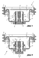
- the entire valve arrangement bears the reference number 1. It comprises a valve disk 2, the whole consists of a plastic, as it is shown in the figures by the corresponding Hatching is indicated.
- the valve disk 2 essentially has a cup-shaped Shape with a pot bottom 7 and a protruding pot wall 3.
- the Wall thickness t of the cup wall 3 of the valve plate 2 is approximately 0.2 mm to approximately 1 mm, preferably 0.3 mm to 0.8 mm.
- a central one Cut out opening 9 which projects through a cylindrical, projecting from the pot bottom 7 Piston guide 8 continues.
- Valve plate 2 made of plastic is equipped with a discharge valve 11, which is a valve piston 12 with a sealing body 13 and a restoring element 15.
- the sealing body 13 is provided with elastic slats, which in the closed state of the Discharge valve 11 sealingly rest on valve seat 10 (Fig. 1).
- the reset element 15 is formed as an annular spring element which between the piston guide 8 and a circumferential shoulder 16 provided on the valve stem 12 is held.
- the valve stem 12 has at least one flow channel 14, which in the open state of the Discharge valve 11 (Fig. 2) together with the central opening 9 of the valve plate Forms an outlet opening for the medium kept under pressure in the pressure cell. How 2, the reset element 15 has a radial Resilience, which is expressed in that the annular spring body 15 when actuated of the discharge valve 11 is radially elastically bendable.
- An external threaded ring 4 forms a coupling device for the can adapter of a dispenser and is thin Connecting webs 5 connected to the peripheral edge of the cup-shaped valve plate 2.
- the connecting webs 5 are equipped with predetermined breaking points 6 indicated by dashed lines, that break when a maximum permissible torque or tilting torque is exceeded.
- Fig. 3 shows the valve assembly of Fig. 1 and 2 in the assembled state.
- the Valve plate 2 is positively connected to the opening edge 21 of the pressure cell 22, especially clinched.
- the circumferential bead created by the clinching is included provided with the reference numeral 23.
- the sealing lip 17 is a pressure-assisted sealing element formed, and amplified by the pressure of the inside the can 22nd stored medium its sealing effect.
- To stiffen the valve plate 2 is one cylindrical stiffening sleeve 18 is provided, which is inserted into the valve plate 2 and is positively connected to the pressure cell 22 together with the valve plate 2.
- the Stiffening sleeve 18 has a bottom section 20 with a central recess, through which the discharge valve 11 is guided, and a cylindrical wall 19 which on the Pot wall 3 of the valve plate 2 abuts. With this arrangement, the valve plate 2 supported both in the bottom area 7 and in the area of the pot wall 3.
- the Stiffening sleeve 18 is a simple deep-drawn part made of sheet metal and has, for example a wall thickness of about 0.2 to about 0.5 mm.
Landscapes
- Chemical & Material Sciences (AREA)
- Dispersion Chemistry (AREA)
- Engineering & Computer Science (AREA)
- Mechanical Engineering (AREA)
- Containers And Packaging Bodies Having A Special Means To Remove Contents (AREA)
Abstract
Description
Die Erfindung betrifft eine Ventilanordnung zur Abgabe von fluiden Medien, die in
Behältnissen, insbesondere in Druckdosen, unter Druck gelagert sind, gemäss dem
Oberbegriff des Patentanspruchs 1.The invention relates to a valve arrangement for dispensing fluid media, which in
Containers, especially in pressure cans, are stored under pressure, according to
Preamble of
In Gewerbe und Industrie, im Haushalt, und in vielen weiteren Anwendungsfällen kommen Druckdosen zum Einsatz, in denen fluide Medien unter Druck aufbewahrt sind. Bei den fluiden Medien kann es sich um Lacke, Schmiermittel, Reinigungsmittel, schäumende Medien und dergleichen mehr handeln. Die Druckdosen weisen üblicherweise eine längliche Form auf und besitzen eine offene Seite, die mittels einer Ventilanordnung verschlossen ist. Die Ventilanordnung umfasst einen Ventilteller, der mit dem Öffnungsrand der länglichen Druckdose verbunden ist und mit einem Austragventil für die fluiden Medien ausgestattet ist. Das Austragventil beinhaltet einen Ventilkörper, einen Ventilsitz mit Dichtungselement, ein Verschlussteil und ein Rückstellelement. Vielfach ist der Ventilteller topfartig ausgebildet und mit Anschlusseinrichtungen für einen Dosenadapter ausgestattet, der es erlaubt, die Druckdose fluiddicht mit einem händisch oder motorisch betätigbaren Austraggerät zu verbinden. Eine gattungsgemässe Ventilanordnung ist beispielsweise aus der EP-B-0 350 779 hinlänglich bekannt. Die bekannte Ventilanordnung ist insbesondere für Aerosoldosen aus Aluminium oder Blech ausgelegt. Diese Dosen besitzen eine genormte Öffnung, deren Durchmesser beispielsweise etwa 1 Zoll beträgt. Die Öffnung ist mit einem Rollrand ausgestattet, der zur Aufnahme des Ventiltellers dient. Nach dem Aufsetzen des Ventiltellers wird dieser durch Verformung formschlüssig mit der Dose verbunden. Dieser Vorgang wird üblicherweise als "clinchen" oder "crimpen" bezeichnet. In trade and industry, in the home, and in many other applications pressure cans are used in which fluid media are kept under pressure. The fluid media can be paints, lubricants, cleaning agents, act foaming media and the like. The sockets usually have elongated in shape and have an open side by means of a valve assembly is closed. The valve arrangement comprises a valve plate, which with the Opening edge of the elongated pressure cell is connected and with a discharge valve for the fluid media is equipped. The discharge valve includes a valve body, a Valve seat with sealing element, a closure part and a return element. Is multiple the valve plate is pot-shaped and with connection devices for a socket adapter equipped that allows the pressure can to be fluid-tight with a manual or to connect motor-operated discharge device. A generic valve arrangement is well known for example from EP-B-0 350 779. The well-known Valve arrangement is especially designed for aerosol cans made of aluminum or sheet metal. These cans have a standardized opening, the diameter of which is about Is 1 inch. The opening is equipped with a rolled edge, which can hold the Serves valve plates. After fitting the valve disc, it becomes deformed positively connected to the can. This process is commonly referred to as "clinching" or "crimping".
Der Ventilteller bildet das zentrale Teil dieser bekannten Ventilanordnungen und besteht aus Metall. Der metallene Ventilteller muss passgenau hergestellt werden und erfordert in der Serienfertigung teure Werkzeuge. Aus Dichtigkeitsgründen weisen die Ventile der bekannten Lösung gemäss der EP-B-0 350 779 einen Ventilsitz aus Kunststoff auf. Um dies zu ermöglichen, muss der metallische Ventilteller in eine Kunststoffspritzform eingelegt werden, in der er mit Kunststoff umspritzt wird. Abgesehen vom zusätzlichen Aufwand, den dieses Herstellverfahren bedeutet, kann zwischen dem metallischen Ventilteller und dem umspritzten Kunststoff ein Spalt verbleiben, durch den beispielsweise ein in der Druckdose befindliches Aerosol entweichen kann. Die Anschlusseinrichtungen für die Verbindung der Druckdose mit einem Austraggerät sind örtlich auf den zylindrischen Innenbereich des topfartigen Ventiltellers beschränkt und sind als Innengewinde ausgebildet. Die Werkzeuge zur Herstellung eines Innengewindes am Ventilteller sind relativ aufwendig und verteuern den Herstellungsprozess. Ausserdem weisen viele bekannte Austraggeräte standardisierte Anschlussteile auf, die auf die Durchmesser von Druckdosen mit Aussengewindeanschlüssen abgestimmt sind. Dadurch sind für die Anbindung der gattungsgemässen Druckdose an derartige Austragvorrichtungen vielfach separate Adapter nötig. Dies schlägt sich in zusätzlichen Kosten für die Herstellung und Beschaffung und in einem erhöhten Montageaufwand nieder.The valve disk forms the central part of these known valve arrangements and exists made of metal. The metal valve disc must be manufactured to fit and requires expensive tools in series production. For reasons of tightness, the valves of the known solution according to EP-B-0 350 779 a valve seat made of plastic. Around To make this possible, the metallic valve disc must be placed in a plastic injection mold in which it is encapsulated with plastic. Apart from the extra effort, which means this manufacturing process can between the metallic valve plate and the molded plastic remains a gap through which, for example aerosol in the pressure can can escape. The connection devices for the connection of the pressure cell with a discharge device are local on the cylindrical Limited interior of the pot-like valve plate and are designed as an internal thread. The tools for creating an internal thread on the valve disk are relative complex and make the manufacturing process more expensive. In addition, many known Discharge devices standardized connection parts based on the diameter of pressure sockets are coordinated with external thread connections. This is for the connection the generic pressure cell on such discharge devices often separate Adapter required. This translates into additional manufacturing and procurement costs and in an increased assembly effort.
Aufgabe der vorliegenden Erfindung ist es daher, eine gattungsgemässe Ventilanordnung für eine Druckdose dahingehend zu verändern, dass den zuvor geschilderten Nachteilen abgeholfen ist. Es soll eine Ventilanordnung geschaffen werden, bei der die Gefahr von Leckagen verhindert ist. Der Herstell- und Montageaufwand für die Ventilanordnung soll reduziert sein. Auf separate Adapterteile soll verzichtet werden können.The object of the present invention is therefore a generic valve arrangement to change for a pressure cell in such a way that the disadvantages described above is remedied. A valve arrangement is to be created in which the risk of Leakage is prevented. The manufacturing and assembly effort for the valve assembly should be reduced. There should be no need for separate adapter parts.
Die Lösung dieser Aufgaben besteht in einer Ventilanordnung zur Abgabe von fluiden
Medien, die in Behältnissen, insbesondere in Druckdosen, unter Druck gelagert sind, mit
den im kennzeichnenden Abschnitt des Patentanspruchs 1 angeführten Merkmalen.
Bevorzugte Ausführungsvarianten und/oder Weiterbildungen der Erfindung sind Gegenstand
der abhängigen Patentansprüche. Die Erfindung betrifft eine Ventilanordnung zur
Abgabe von fluiden Medien, die in zylindrischen Behältnissen, insbesondere in Druckdosen,
unter Druck gelagert sind, umfasst einen topfförmig ausgebildeten Ventilteller, der
mit der offenen Seite der Druckdose verbindbar ist und eine Kupplungseinrichtung für
einen Dosenadapter eines Austraggerätes aufweist. Der Ventilteller ist mit einem Austragventil
ausgestattet, das einen Ventilkolben und ein Rückstellelement umfasst.
Erfindungsgemäss besteht der topfförmige Ventilteller aus Kunststoff und weist eine
plastisch verformbare, insbesondere clinchbare, zylindrische Topfwandung auf. Die
Kupplungseinrichtung ist ein integrales Anschlussteil, vorzugsweise ein zylindrischer
Aussengewindering, aus Kunststoff, das über dünne Verbindungsstege mit dem äusseren
Umfangsrand der Topfwandung des Ventiltellers verbunden ist.The solution to these problems consists in a valve arrangement for dispensing fluids
Media that are stored in containers, especially in pressure cans, under pressure
the features stated in the characterizing section of
Indem der topfförmige Ventilteller gesamthaft als Kunststoffteil ausgebildet ist, entfällt das bei den aus dem Stand der Technik bekannten Ventiltellern aus Dichtigkeitsgründen und für den Korrosionsschutz erforderliche, nachträgliche Umspritzen des Ventiltellers mit Kunststoff. Dadurch werden Spalte, die zwischen dem metallischen Ventilteller und dem umspritzten Kunststoff auftreten und Undichtigkeiten der Druckdose verursachen können, vermieden. Das in die Druckdose eingefüllte Medium kommt nur mit dem Kunststoffventilteller in Kontakt. Der Kunststoffventilteller erfüllt gleichzeitig die Abdichtfunktion. Der Ventilteller aus Kunststoff ist einfach und kostengünstig in der Herstellung und in der Montage. Die für die Montage an einem manuellen bzw. motorisch betätigbaren Austraggerät erforderliche Kupplungseinrichtung ist integral mit dem Ventilteller ausgebildet. Dies erleichtert die Herstellung des Ventiltellers und des Anschlussteils in einem Arbeitsschritt. Die dünnen Verbindungsstege, über die das Anschlussteil mit dem Ventilteller aus Kunststoff verbunden ist, verhindern die Übertragung eines unzulässig grossen Dreh- oder Kippmoments auf den Ventilteller. Das Anschlussteil kann beispielsweise Teil eines Bajonettverschlusses sein. Aus fertigungstechnischen Gründen ist es bevorzugt als ein zylindrischer Aussengewindering ausgebildet. Die dünnen Verbindungsstege brechen, bevor der mit dem Öffnungsrand der Druckdose verclinchte Ventilteller gegenüber der Druckdose verdreht oder durch Verkippen abgehoben werden kann. Das von den dünnen Verbindungsstegen gerade noch übertragbare Solldrehmoment beträgt etwa 5 Nm. Bei grösseren Drehmomenten kommt es zu einem Bruch der Verbindungsstege. Für die Festigkeit gegenüber Verkippen gelten für die Verbindungsstege etwa die gleichen Festigkeiten. Dadurch ist zuverlässig verhindert, dass die Druckdose durch Fehlmanipulationen geöffnet und der Anwender mit dem unter Druck in der Druckdose gelagerten Inhalt in Kontakt kommen kann.This is eliminated by designing the cup-shaped valve disk as a plastic part in the valve plates known from the prior art for reasons of tightness and subsequent overmolding of the valve disc required for corrosion protection Plastic. This will create gaps between the metallic valve disc and the molded plastic can occur and cause leaks in the pressure cell, avoided. The medium filled into the pressure can only comes with the plastic valve disc in contact. The plastic valve disc also fulfills the sealing function. The Valve plate made of plastic is simple and inexpensive to manufacture and in Assembly. The for mounting on a manual or motorized discharge device required coupling device is integrally formed with the valve plate. This facilitates the manufacture of the valve plate and the connecting part in one Work step. The thin connecting webs, over which the connecting part with the Valve plate is connected from plastic, prevent the transfer of an impermissible large torque or tilting moment on the valve plate. The connector can for example, be part of a bayonet catch. For technical reasons it is preferably designed as a cylindrical external threaded ring. The thin ones Break the connecting webs before they connect to the opening edge of the pressure cell Valve disc rotated relative to the pressure cell or lifted off by tilting it can. That which can just be transferred by the thin connecting bars The target torque is approximately 5 Nm. At higher torques there is a Breakage of the connecting webs. For the strength against tilting apply to the Connecting webs about the same strength. This reliably prevents that the pressure cell is opened by incorrect manipulation and the user with the under Pressure stored in the pressure cell can come into contact.
Die Verbindungsstege des Anschlussteils mit dem Ventilteller sind mit Vorteil mit Sollbruchstellen ausgestattet. Dadurch ist sichergestellt, dass auch bei fertigungstechnisch bedingten Toleranzen in den Wandstärken der Stege die zulässigen Dreh- und Kippmomente nicht überschritten werden.The connecting webs of the connecting part with the valve disk are advantageous with Predetermined breaking points. This ensures that even in manufacturing technology conditional tolerances in the wall thicknesses of the webs the permissible turning and Tilting moments are not exceeded.
Um eine zuverlässige Dichtigkeit der Verbindung des Ventiltellers und des Öffnungsrands der Druckdose zu gewährleisten, wird der Ventilteller beim Verclinchen stark verformt. To ensure reliable sealing of the connection between the valve disc and the opening edge to ensure the pressure cell, the valve disk is strongly deformed when clinching.
Dabei erweisen sich Wandstärken des Ventiltellers im Bereich der plastisch verformbaren Topfwandung von etwa 0,2 mm bis etwa 1,0 mm, vorzugsweise 0,3 mm bis 0,8 mm, als zweckmässig. Bei diesen Wandstärken ist, je nach Art des verwendeten Kunststoffes, eine ausreichende Eigensteifigkeit des Ventiltellers gewährleistet, und die für den Verformungsvorgang bei der Verbindung mit dem Öffnungsrand erforderlichen Kräfte können ohne weitere Modifikationen von den bekannten Geräten aufgebracht werden.Here, wall thicknesses of the valve plate in the area of the plastically deformable are proven Pot wall from about 0.2 mm to about 1.0 mm, preferably 0.3 mm to 0.8 mm, as expedient. With these wall thicknesses, depending on the type of plastic used, a sufficient inherent rigidity of the valve plate is guaranteed, and that for the deformation process forces required when connecting to the opening edge can be applied without further modifications from the known devices.
Die erfindungsgemässe Ausbildung des Ventiltellers mit integralem Anschlussteil, insbesondere einem Aussengewindering, ermöglicht auch den Einsatz kostengünstiger Fertigungsverfahren. Vorzugsweise wird dabei auf die bekannten Spritzgiessverfahren zurückgegriffen, die eine einfache und schnelle Herstellung grosser Mengen der benötigten Teile ermöglichen.The inventive design of the valve plate with an integral connecting part, in particular an external threaded ring, also enables the use to be made more economically Manufacturing process. The known injection molding process is preferred resorted to the simple and quick production of large quantities of allow necessary parts.
Zur weiteren Erhöhung der Dichtigkeit der Verbindung des Kunststoffventiltellers mit dem Öffnungsrand der Druckdose ist in einer vorteilhaften Variante der Erfindung eine zusätzliche Nebenabdichtung vorgesehen. Die Nebenabdichtung ist als ringförmige, vorzugsweise elastische, Dichtlippe ausgebildet, die an der dem Austragventil abgewandten Seite des Umfangsrandes von der Topfwandung des Ventiltellers abragt. Die Dichtlippe kann als druckunterstütztes Dichtelement ausgebildet sein, das bei Druckbelastung die Dichtwirkung erhöht.To further increase the tightness of the connection of the plastic valve plate with the In an advantageous variant of the invention, the opening edge of the pressure cell is an additional one Auxiliary sealing provided. The secondary seal is preferably annular elastic, sealing lip formed on the side facing away from the discharge valve of the peripheral edge protrudes from the cup wall of the valve plate. The sealing lip can be designed as a pressure-assisted sealing element, the the under pressure Sealing effect increased.
Es erweist sich von Vorteil, wenn das Rückstellelement, bezogen auf die Ausströmrichtung des fluiden Mediums, nach dem Ventilsitz angeordnet ist. Indem das Rückstellelement nicht mehr ständig in Kontakt mit dem in der Druckdose aufbewahrten Medium ist, besteht eine grössere Auswahl hinsichtlich der einsetzbaren Materialien.It proves advantageous if the restoring element is based on the outflow direction of the fluid medium, is arranged after the valve seat. By the reset element no longer in constant contact with the medium stored in the pressure can there is a larger selection with regard to the materials that can be used.
In einer Variante der Erfindung ist das Rückstellelement als ringförmiger Federkörper ausgebildet. Der ringförmige Federkörper ist zwischen einer ringförmig am Ventilkolben umlaufenden Schulter und einer vom Ventilteller axial abragenden, zylindrischen Kolbenführung elastisch federbar gehalten. Der ringförmige Federkörper kann beispielsweise in unmittelbarer Fortsetzung der zylindrischen Kolbenführung mit angespritzt werden. Als Material kommt dabei ein spritztechnisch verarbeitbares, thermoplastisches Elastomer in Frage. Der ringförmige Federkörper kann beispielsweise auch als separater Teil aus einem gummiartigen Werkstoff vorliegen, der auf den Ventilkolben aufgesteckt wird. Der aus Gummi oder einem Elastomer bestehende ringförmige Federkörper bildet beim Anschluss der Druckdose an ein Austraggerät eine zusätzliche Abdichtung. Der Federkörper kann auch von einer metallischen Schraubenfeder oder dergleichen Elementen gebildet sein. Die gummielastischen Federkörper bzw. die angespritzten, federnden Kunststoffringe sind bei der Betätigung des Austragventiles vorzugsweise radial ausfederbar.In a variant of the invention, the restoring element is in the form of an annular spring body educated. The annular spring body is between an annular on the valve piston circumferential shoulder and a cylindrical piston guide projecting axially from the valve disk held elastically resilient. The annular spring body can, for example, in immediate continuation of the cylindrical piston guide. As A thermoplastic elastomer that can be processed by injection molding comes into the material Question. The annular spring body can, for example, also consist of a separate part a rubber-like material that is attached to the valve piston. The ring-shaped spring body made of rubber or an elastomer forms the Connection of the pressure cell to a discharge device an additional seal. The Spring body can also be made of a metallic coil spring or similar elements be educated. The rubber-elastic spring body or the molded, springy Plastic rings are preferably radial when the discharge valve is actuated reboundable.
In einer sehr vorteilhaften Variante einer mit einem erfindungsgemässen Ventilteller ausgestatteten Druckdose ist der am Öffnungsrand montierte topfförmige Ventilteller durch eine zylindrische, vorzugsweise metallische, Versteifungshülse mit einem Bodenabschnitt verstärkt. Die topfartige Versteifungshülse ist an der der Ventilanordnung zugewandten Topfwandung des Ventiltellers angeordnet und zusammen mit dem Ventilteller mit dem Öffnungsrand der Druckdose formschlüssig verbunden, insbesondere geclincht. Durch die Versteifungshülse ist auch bei Ventiltellern, die aufgrund der Materialwahl und der Wandstärke eine geringere Eigenstabilität aufweisen, die formschlüssige Verbindung mit dem Öffnungsrand der Druckdose dauerhaft gesichert. Die bei einer gefüllten Druckdose auf den Ventilteller einwirkenden Axialkräfte werden zuverlässig aufgenommen. Die Dichtigkeit bleibt gewährleistet. Die topfartige Versteifungshülse ist vorzugsweise ein einfaches Tiefziehteil mit einer Wandstärke von etwa 0,2 mm bis etwa 0,5 mm und ohne grössere Anforderungen an die Oberflächengüte und die Masshaltigkeit. Die zylindrische Wandung der Versteifungshülse stützt den dünnwandigen Bereich des Kunststoffventiltellers. Der Bodenabschnitt der Versteifungshülse stützt den druckbelasteten Boden des Ventiltellers. Die Werkzeug- und Herstellkosten für eine derartig ausgebildete Versteifungshülse sind vergleichsweise gering.In a very advantageous variant of one with a valve disk according to the invention equipped pressure cell is the cup-shaped valve plate mounted on the opening edge through a cylindrical, preferably metallic, stiffening sleeve with a bottom section reinforced. The pot-like stiffening sleeve is on the valve assembly facing Pot wall of the valve plate arranged and together with the valve plate positively connected to the opening edge of the pressure cell, in particular clinched. Due to the stiffening sleeve is also with valve plates due to the choice of material and the wall thickness has less inherent stability, the positive connection permanently secured with the opening edge of the pressure cell. The one with a filled pressure can Axial forces acting on the valve plate are reliably absorbed. The Tightness remains guaranteed. The pot-like stiffening sleeve is preferably a simple deep-drawn part with a wall thickness of about 0.2 mm to about 0.5 mm and without greater demands on the surface quality and dimensional accuracy. The cylindrical Wall of the stiffening sleeve supports the thin-walled area of the plastic valve disc. The bottom section of the stiffening sleeve supports the pressure-loaded bottom of the Valve plates. The tool and manufacturing costs for such a stiffening sleeve are comparatively small.
Im folgenden wird die Erfindung unter Bezugnahme auf ein in den Figuren schematisch dargestelltes Ausführungsbeispiel näher erläutert. Es zeigen in nicht massstabsgetreuer Darstellung:
- Fig. 1
- eine erfindungsgemässe Ventilanordnung;
- Fig. 2
- die Ventilanordnung aus Fig. 1 mit geöffnetem Austragventil; und
- Fig. 3
- die Ventilanordnung aus Fig. 1 in montiertem Zustand.
- Fig. 1
- a valve arrangement according to the invention;
- Fig. 2
- the valve assembly of Figure 1 with the discharge valve open. and
- Fig. 3
- the valve assembly of Fig. 1 in the assembled state.
In den Fig. 1 - 3 sind gleiche Elemente jeweils mit gleichen Bezugszeichen versehen. Die
Ventilanordnung trägt gesamthaft das Bezugszeichen 1. Sie umfasst einen Ventilteller 2,
der gesamthaft aus einem Kunststoff besteht, wie es in den Fig. auch durch die entsprechende
Schraffur angedeutet ist. Der Ventilteller 2 besitzt im wesentlichen eine topfförmige
Gestalt mit einem Topfboden 7 und einer davon abragenden Topfwandung 3. Die
Wandstärke t der Topfwandung 3 des Ventiltellers 2 beträgt etwa 0,2 mm bis etwa 1 mm,
vorzugsweise 0,3 mm bis 0,8 mm. Im Topfboden 7 des Ventiltellers 2 ist eine zentrale
Öffnung 9 ausgespart, die sich durch eine vom Topfboden 7 abragende, zylindrische
Kolbenführung 8 fortsetzt. Der die zentrale Öffnung 9 berandende Abschnitt der von der
Kolbenführung 8 abgewandten Seite des Ventiltellers 2 bildet einen Ventilsitz 10. Der
Ventilteller 2 aus Kunststoff ist mit einem Austragventil 11 ausgestattet, das einen Ventilkolben
12 mit einem Dichtungskörper 13 und ein Rückstellelement 15 umfasst. Der Dichtungskörper
13 ist mit elastischen Lamellen versehen, die im geschlossenen Zustand des
Austragventils 11 dichtend am Ventilsitz 10 anliegen (Fig. 1). Das Rückstellelement 15 ist
als ein ringförmiges Federelement ausgebildet, das zwischen der Kolbenführung 8 und
einer am Ventilschaft 12 vorgesehenen, umlaufenden Schulter 16 gehalten ist. Der Ventilschaft
12 weist wenigstens einen Durchströmkanal 14 auf, der im geöffneten Zustand des
Austragventils 11 (Fig. 2) zusammen mit der zentralen Öffnung 9 des Ventiltellers eine
Austrittsöffnung für das in der Druckdose unter Druck aufbewahrte Medium bildet. Wie
insbesondere aus Fig. 2 ersichtlich ist, besitzt das Rückstellelement 15 eine radiale
Federbarkeit, die sich darin äussert, dass der ringförmige Federkörper 15 bei Betätigung
des Austragventils 11 radial elastisch ausknickbar ist.1-3, the same elements are provided with the same reference numerals. The
The entire valve arrangement bears the
Von der dem Austragventil 11 abgewandten Unterseite des Ventiltellers 2 ragt eine
umlaufende Dichtlippe 17 ab, die im montierten Zustand des Ventiltellers 2 eine Nebenabdichtung
zur Druckdose bildet. Die Wandstärke der Dichtlippe 17 ist derart bemessen,
dass eine elastische Verformbarkeit gewährleistet ist. Ein Aussengewindering 4 bildet
eine Kupplungseinrichtung für den Dosenadapter eines Austraggeräts und ist über dünne
Verbindungsstege 5 mit dem Umfangsrand des topfförmigen Ventiltellers 2 verbunden.
Die Verbindungsstege 5 sind mit strichliert angedeuteten Sollbruchstellen 6 ausgestattet,
die brechen, wenn ein maximal zulässiges Dreh- oder Kippmoment überschritten wird.One protrudes from the underside of the
Fig. 3 zeigt die Ventilanordnung aus Fig. 1 bzw. 2 im montierten Zustand. Dabei ist der
Ventilteller 2 mit dem Öffnungsrand 21 der Druckdose 22 formschlüssig verbunden,
insbesondere geclincht. Die durch die Clinchung entstehende, umlaufende Sicke ist mit
dem Bezugszeichen 23 versehen. Die Dichtlippe 17 ist als ein druckunterstütztes Dichtelement
ausgebildet, und verstärkt durch den Druck des innerhalb der Druckdose 22
gelagerten Mediums seine Dichtwirkung. Zur Aussteifung des Ventiltellers 2 ist eine
zylindrische Versteifungshülse 18 vorgesehen, die in den Ventilteller 2 eingelegt und
gemeinsam mit dem Ventilteller 2 formschlüssig mit der Druckdose 22 verbunden ist. Die
Versteifungshülse 18 besitzt einen Bodenabschnitt 20 mit einer zentralen Aussparung,
durch die das Austragventil 11 geführt ist, und eine zylindrische Wandung 19, die an der
Topfwandung 3 des Ventiltellers 2 anliegt. Durch diese Anordnung ist der Ventilteller 2
sowohl im Bodenbereich 7 als auch im Bereich der Topfwandung 3 unterstützt. Die
Versteifungshülse 18 ist ein einfaches Tiefziehteil aus Blech und weist beispielsweise
eine Wandstärke von etwa 0,2 bis etwa 0,5 mm auf.Fig. 3 shows the valve assembly of Fig. 1 and 2 in the assembled state. Here is the
Claims (10)
Applications Claiming Priority (2)
| Application Number | Priority Date | Filing Date | Title |
|---|---|---|---|
| DE19937283 | 1999-08-06 | ||
| DE19937283A DE19937283A1 (en) | 1999-08-06 | 1999-08-06 | Valve arrangement for dispensing fluid media stored under pressure in containers |
Publications (2)
| Publication Number | Publication Date |
|---|---|
| EP1074484A1 true EP1074484A1 (en) | 2001-02-07 |
| EP1074484B1 EP1074484B1 (en) | 2004-05-19 |
Family
ID=7917534
Family Applications (1)
| Application Number | Title | Priority Date | Filing Date |
|---|---|---|---|
| EP00810673A Expired - Lifetime EP1074484B1 (en) | 1999-08-06 | 2000-07-27 | Valve assembly for dispensing fluids stored under pressure in a container |
Country Status (3)
| Country | Link |
|---|---|
| US (1) | US6371338B1 (en) |
| EP (1) | EP1074484B1 (en) |
| DE (2) | DE19937283A1 (en) |
Cited By (2)
| Publication number | Priority date | Publication date | Assignee | Title |
|---|---|---|---|---|
| EP2028131A2 (en) * | 2007-08-24 | 2009-02-25 | Werner, Hans Jürgen | Solid matter valve |
| EP2287088A1 (en) | 2009-08-19 | 2011-02-23 | Altachem Holdings NV | Valve with safety protrusion |
Families Citing this family (24)
| Publication number | Priority date | Publication date | Assignee | Title |
|---|---|---|---|---|
| US6796478B2 (en) | 2000-10-12 | 2004-09-28 | Illinois Tool Works Inc. | Fuel cell adapter system for combustion tools |
| US6523860B1 (en) | 2000-10-12 | 2003-02-25 | Illinois Tool Works Inc. | Fuel cell adapter system for combustion tools |
| DE20116336U1 (en) | 2001-10-05 | 2001-12-06 | Aerosol-Technik LINDAL GmbH, 23843 Bad Oldesloe | Valve arrangement for a pressurized fluid container |
| US6786378B2 (en) | 2002-01-09 | 2004-09-07 | Illinois Tool Works Inc. | Fastener tool having auxiliary fuel cell metering valve stem seal adaptor |
| EP1485309B1 (en) * | 2002-01-24 | 2009-11-18 | Rathor Ag | Valve |
| US20060138178A1 (en) * | 2002-10-31 | 2006-06-29 | Scheindel Christian T | Axially actuated valve for dispensing pressurized product |
| US8210400B2 (en) * | 2002-10-31 | 2012-07-03 | Christian T. Scheindel | Valve for use in a container which employs pressure to dispense product |
| US6938810B2 (en) | 2003-04-15 | 2005-09-06 | Illinois Tool Works Inc. | Fuel cell adapter system for combustion tools |
| PL1812317T3 (en) * | 2004-10-04 | 2012-05-31 | Clayton Corp | Valve for aerosol can |
| DE102008051888B4 (en) * | 2008-10-16 | 2011-02-03 | C. Ehrensperger Ag | Valve for a container for delivery of pressurized fluid |
| US8245888B2 (en) * | 2008-10-24 | 2012-08-21 | S.C. Johnson & Son, Inc. | Barrier piston with seal |
| DE102011082911A1 (en) * | 2011-09-19 | 2013-03-21 | Hilti Aktiengesellschaft | Fire protection element |
| USD794781S1 (en) * | 2015-04-13 | 2017-08-15 | Medela Holding Ag | Valve component for a breastmilk collection system |
| US10598377B2 (en) | 2016-05-27 | 2020-03-24 | Illinois Tool Works Inc. | Combustion-powered fastener driving tool fuel cell assembly |
| USD812101S1 (en) * | 2016-05-27 | 2018-03-06 | Illinois Tool Works Inc. | Combination fuel cell adapter and cap |
| USD831201S1 (en) | 2016-08-29 | 2018-10-16 | Medela Holding Ag | Safety valve component for a breastmilk collection system |
| US20180339841A1 (en) * | 2017-05-26 | 2018-11-29 | The Procter & Gamble Company | Sheath to protect an aerosol valve stem |
| US10501258B2 (en) | 2017-05-26 | 2019-12-10 | The Procter & Gamble Company | Aerosol dispenser having annular seals and aerosol container therefor |
| US10557738B2 (en) | 2017-09-11 | 2020-02-11 | Black & Decker Inc. | External fuel metering valve with shuttle mechanism |
| BE1025177B1 (en) * | 2017-09-21 | 2018-11-29 | Altachem Nv | VALVE FOR A HOLDER |
| DE202020000677U1 (en) * | 2019-02-27 | 2020-03-20 | Aptar Dortmund Gmbh | Valve and dispenser |
| USD1001736S1 (en) | 2020-09-01 | 2023-10-17 | Illinois Tool Works Inc. | Fuel cell adapter for tool |
| US11978915B2 (en) | 2020-09-01 | 2024-05-07 | Illinois Tool Works Inc. | Combustion-powered fastener driving tool fuel cell adapter |
| US11992925B2 (en) | 2021-11-23 | 2024-05-28 | Illinois Tool Works Inc. | Fuel cell adapter for fastener driving tool |
Citations (5)
| Publication number | Priority date | Publication date | Assignee | Title |
|---|---|---|---|---|
| US3817297A (en) * | 1971-08-20 | 1974-06-18 | H King | Reusable aerosol dispenser |
| GB1505530A (en) * | 1974-06-14 | 1978-03-30 | Aerosol Inventions Dev | Valves for pressurised dispensers |
| GB2096245A (en) * | 1981-04-07 | 1982-10-13 | Coster Tecnologie Speciali Spa | A dispensing device for pastes, creams and thick liquids |
| US4522318A (en) * | 1980-12-19 | 1985-06-11 | Luigi Del Bon | Discharge valve for use in a pressurized container |
| US4852807A (en) * | 1988-03-28 | 1989-08-01 | Stoody William R | Neoteric simplified aerosol valve |
Family Cites Families (4)
| Publication number | Priority date | Publication date | Assignee | Title |
|---|---|---|---|---|
| FR2508136B1 (en) * | 1981-06-19 | 1985-12-06 | Oreal | IMPROVEMENT IN VALVES FOR AEROSOL CONTAINERS |
| JPH0335399Y2 (en) * | 1985-11-08 | 1991-07-26 | ||
| FR2636314B1 (en) * | 1988-09-12 | 1990-11-16 | Oreal | DEVICE FOR FIXING A VALVE ON A PRESSURIZED CONTAINER AND CONTAINER PROVIDED WITH SUCH A DEVICE |
| FR2777967B1 (en) * | 1998-04-28 | 2000-06-16 | Oreal | VALVE ACTIVATION MEMBER, VALVE EQUIPPED WITH THIS MEMBER AND DISTRIBUTION ASSEMBLY PROVIDED WITH THIS VALVE |
-
1999
- 1999-08-06 DE DE19937283A patent/DE19937283A1/en not_active Withdrawn
-
2000
- 2000-07-19 US US09/618,874 patent/US6371338B1/en not_active Expired - Lifetime
- 2000-07-27 EP EP00810673A patent/EP1074484B1/en not_active Expired - Lifetime
- 2000-07-27 DE DE50006463T patent/DE50006463D1/en not_active Expired - Fee Related
Patent Citations (5)
| Publication number | Priority date | Publication date | Assignee | Title |
|---|---|---|---|---|
| US3817297A (en) * | 1971-08-20 | 1974-06-18 | H King | Reusable aerosol dispenser |
| GB1505530A (en) * | 1974-06-14 | 1978-03-30 | Aerosol Inventions Dev | Valves for pressurised dispensers |
| US4522318A (en) * | 1980-12-19 | 1985-06-11 | Luigi Del Bon | Discharge valve for use in a pressurized container |
| GB2096245A (en) * | 1981-04-07 | 1982-10-13 | Coster Tecnologie Speciali Spa | A dispensing device for pastes, creams and thick liquids |
| US4852807A (en) * | 1988-03-28 | 1989-08-01 | Stoody William R | Neoteric simplified aerosol valve |
Cited By (6)
| Publication number | Priority date | Publication date | Assignee | Title |
|---|---|---|---|---|
| EP2028131A2 (en) * | 2007-08-24 | 2009-02-25 | Werner, Hans Jürgen | Solid matter valve |
| EP2028131A3 (en) * | 2007-08-24 | 2010-05-26 | Werner, Hans Jürgen | Solid matter valve |
| EP2287088A1 (en) | 2009-08-19 | 2011-02-23 | Altachem Holdings NV | Valve with safety protrusion |
| WO2011020864A1 (en) | 2009-08-19 | 2011-02-24 | Altachem Holding Nv | Valve with safety protrusion |
| CN102574628A (en) * | 2009-08-19 | 2012-07-11 | 艾尔塔彻姆控股公司 | Valve with safety protrusion |
| US20130200111A1 (en) * | 2009-08-19 | 2013-08-08 | Faigle Kunststoffe Gmbh | Valve with safety protrusion |
Also Published As
| Publication number | Publication date |
|---|---|
| EP1074484B1 (en) | 2004-05-19 |
| DE19937283A1 (en) | 2001-02-15 |
| US6371338B1 (en) | 2002-04-16 |
| DE50006463D1 (en) | 2004-06-24 |
Similar Documents
| Publication | Publication Date | Title |
|---|---|---|
| EP1074484B1 (en) | Valve assembly for dispensing fluids stored under pressure in a container | |
| DE69024668T2 (en) | Dispensing device for at least one liquid product, in particular of a cosmetic or pharmaceutical type | |
| EP2247711B1 (en) | Bioreactor | |
| DE1946734U (en) | FILTERS FOR FLOWING MEDIA, IN PARTICULAR OIL FILTERS. | |
| DE1057289B (en) | Atomizer for substances kept under pressure in a container made of glass, especially liquids | |
| EP0550503A1 (en) | Non-returnable pressure vessel, especially as a filling container for cooling and air conditioning installations. | |
| DE69832522T2 (en) | TANK QUICK CONNECTION WITH CHECK VALVE | |
| EP0367287B1 (en) | Diaphragm valve with an elastic diaphragm supported by the valve cover | |
| EP0654010A1 (en) | Check valve made of plastic. | |
| DE69011520T2 (en) | CONNECTOR AND DETACHABLE COUPLING ARRANGEMENT FOR A FLUID CONTAINER. | |
| EP3366961A1 (en) | Membrane valve with free passthrough | |
| DE602004006457T2 (en) | valve assembly | |
| EP1728559A1 (en) | Manual dispenser for a fluid | |
| WO1999028605A1 (en) | Sealing cap | |
| EP0696545A1 (en) | Dispensing valve for pressurised fluids | |
| DE10224245A1 (en) | Shut-off valve for a pressurized container and container | |
| EP0921299B1 (en) | Device for sealing a fuel pumping device in a fuel tank | |
| EP1124738A1 (en) | Valve for releasing pressurised liquids | |
| WO1997015771A1 (en) | Solenoid valve with a lift armature | |
| DE3708774A1 (en) | Valve for a liquid container that can be separated from a connection line | |
| WO2005047665A1 (en) | Sealing lid for a motor vehicle radiator | |
| EP1549867B1 (en) | Bottoms drainage valves designed in particular for enamelled containers | |
| WO2002076626A1 (en) | Dispensing device for fluids | |
| DE7305218U (en) | VALVE | |
| DE1293092B (en) | Auxiliary valve operated by gravity for a container with a riser pipe designed to dispense fluids under permanent pressure |
Legal Events
| Date | Code | Title | Description |
|---|---|---|---|
| PUAI | Public reference made under article 153(3) epc to a published international application that has entered the european phase |
Free format text: ORIGINAL CODE: 0009012 |
|
| AK | Designated contracting states |
Kind code of ref document: A1 Designated state(s): DE FR GB |
|
| AX | Request for extension of the european patent |
Free format text: AL;LT;LV;MK;RO;SI |
|
| 17P | Request for examination filed |
Effective date: 20010807 |
|
| AKX | Designation fees paid |
Free format text: DE FR GB |
|
| GRAP | Despatch of communication of intention to grant a patent |
Free format text: ORIGINAL CODE: EPIDOSNIGR1 |
|
| GRAS | Grant fee paid |
Free format text: ORIGINAL CODE: EPIDOSNIGR3 |
|
| GRAA | (expected) grant |
Free format text: ORIGINAL CODE: 0009210 |
|
| AK | Designated contracting states |
Kind code of ref document: B1 Designated state(s): DE FR GB |
|
| REG | Reference to a national code |
Ref country code: GB Ref legal event code: FG4D Free format text: NOT ENGLISH |
|
| REF | Corresponds to: |
Ref document number: 50006463 Country of ref document: DE Date of ref document: 20040624 Kind code of ref document: P |
|
| GBT | Gb: translation of ep patent filed (gb section 77(6)(a)/1977) |
Effective date: 20040802 |
|
| ET | Fr: translation filed | ||
| PLBE | No opposition filed within time limit |
Free format text: ORIGINAL CODE: 0009261 |
|
| STAA | Information on the status of an ep patent application or granted ep patent |
Free format text: STATUS: NO OPPOSITION FILED WITHIN TIME LIMIT |
|
| 26N | No opposition filed |
Effective date: 20050222 |
|
| PGFP | Annual fee paid to national office [announced via postgrant information from national office to epo] |
Ref country code: DE Payment date: 20070705 Year of fee payment: 8 |
|
| PGFP | Annual fee paid to national office [announced via postgrant information from national office to epo] |
Ref country code: GB Payment date: 20070725 Year of fee payment: 8 |
|
| PGFP | Annual fee paid to national office [announced via postgrant information from national office to epo] |
Ref country code: FR Payment date: 20070710 Year of fee payment: 8 |
|
| GBPC | Gb: european patent ceased through non-payment of renewal fee |
Effective date: 20080727 |
|
| PG25 | Lapsed in a contracting state [announced via postgrant information from national office to epo] |
Ref country code: DE Free format text: LAPSE BECAUSE OF NON-PAYMENT OF DUE FEES Effective date: 20090203 |
|
| REG | Reference to a national code |
Ref country code: FR Ref legal event code: ST Effective date: 20090331 |
|
| PG25 | Lapsed in a contracting state [announced via postgrant information from national office to epo] |
Ref country code: GB Free format text: LAPSE BECAUSE OF NON-PAYMENT OF DUE FEES Effective date: 20080727 |
|
| PG25 | Lapsed in a contracting state [announced via postgrant information from national office to epo] |
Ref country code: FR Free format text: LAPSE BECAUSE OF NON-PAYMENT OF DUE FEES Effective date: 20080731 |