EP1073938B1 - Verfahren und anordnung zur auswahl von zu überwachenden sicherheitsparametern - Google Patents
Verfahren und anordnung zur auswahl von zu überwachenden sicherheitsparametern Download PDFInfo
- Publication number
- EP1073938B1 EP1073938B1 EP99914536A EP99914536A EP1073938B1 EP 1073938 B1 EP1073938 B1 EP 1073938B1 EP 99914536 A EP99914536 A EP 99914536A EP 99914536 A EP99914536 A EP 99914536A EP 1073938 B1 EP1073938 B1 EP 1073938B1
- Authority
- EP
- European Patent Office
- Prior art keywords
- memory
- monitored
- spsr
- spst
- safety parameters
- Prior art date
- Legal status (The legal status is an assumption and is not a legal conclusion. Google has not performed a legal analysis and makes no representation as to the accuracy of the status listed.)
- Expired - Lifetime
Links
Images

Classifications
-
- G—PHYSICS
- G05—CONTROLLING; REGULATING
- G05B—CONTROL OR REGULATING SYSTEMS IN GENERAL; FUNCTIONAL ELEMENTS OF SUCH SYSTEMS; MONITORING OR TESTING ARRANGEMENTS FOR SUCH SYSTEMS OR ELEMENTS
- G05B19/00—Program-control systems
- G05B19/02—Program-control systems electric
- G05B19/18—Numerical control [NC], i.e. automatically operating machines, in particular machine tools, e.g. in a manufacturing environment, so as to execute positioning, movement or co-ordinated operations by means of program data in numerical form
- G05B19/406—Numerical control [NC], i.e. automatically operating machines, in particular machine tools, e.g. in a manufacturing environment, so as to execute positioning, movement or co-ordinated operations by means of program data in numerical form characterised by monitoring or safety
- G05B19/4061—Avoiding collision or forbidden zones
Definitions
- the invention relates to a method for selecting security parameters to be monitored depending on the configuration of a machine tool or a robot and an arrangement for carrying it out of the procedure.
- Such monitoring has the disadvantage that it is not flexible enough and does not adhere to different configurations of a machine tool can be adjusted.
- the entire program must be changed if a detail on the monitoring system, for example a security parameter or a Detector is changed.
- Monitoring programs of this type are also designed due to more and more and more to be monitored Operating states of the machine tool are increasingly complicated and therefore neither easy to maintain nor easily modifiable.
- EP-A-0 311 062 the monitoring of a sensor is one Motor vehicle described. Motor vehicle type-specific parameters are stored for different types of motor vehicles. With everyone Starting process, the sensor activates the corresponding parameters in Dependency of the motor vehicle in which it is installed.
- the object of the present invention is to provide a method for selecting security parameters to be monitored depending on the Configuration of a machine tool or a robot and a Specify an arrangement for performing the method, said Disadvantages are avoided. It is supposed to be a flexible storage concept and selection of security parameters depending on the configuration machine tool or robot.
- the method according to the invention has the advantage that a memory is provided in the for each possible configuration of the machine tool the security parameters to be monitored, such as Door contact switch of the protective doors or the lines via which the signals the door contact switch to be monitored are transmitted, and / or the coordinates of the shelters or the lines to be monitored the coordinates to be monitored are stored are.
- a memory is addressed and from a stored therein
- the table shows the safety parameters to be monitored for each axis, e.g. Door contacts of the relevant protective doors and the minimum and maximum actual positions for each axis.
- the invention Monitoring program uses these read from the memory Security parameters and can therefore be designed universally be so that it is independent of a special configuration of a machine tool is.
- a processor checks at certain intervals whether all protective contact switches issued by the memory are closed signal and whether the actual positions of the axes within the Shelter. As a result, not all door contact switches always have to and all actual positions of the axes are monitored, but only those for a safe operating state of the machine tool in the special Configuration are relevant. Should a monitored protective door be recognized as open or be an axis position outside the shelter error handling triggered. With this error handling Measures taken to restore a safe operating state e.g. the axis identified as faulty is stopped and sent to the user a corresponding message is issued.
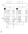
- Output signals from detectors for the configuration of the machine tool are sent to the address bus of two memories SPST and SPSR via lines KI1 to KIn.
- the n lines KI1 to KIn can thus signal 2 n different configurations K0 to K2 n -1 of the machine tool to be monitored.
- a table is stored in the memory SPST, which is partially read out on the basis of the configuration K0 to K2 n -1 supplied.
- the first line of the table is read out for a configuration K0, the second line etc. for a configuration K1.
- the safety parameters to be monitored for this configuration of the machine tool for example door contact switches, are arranged in each line of the table in the memory SPST, arranged according to the axes A1 to Ak of the machine tool for which they signal a safe or unsafe operating state.
- the table assigns the door contact switches to each axis A1 to Ak, whose associated protective doors must be closed for a safe operating state.
- a column of the table is provided for each axis A1 to Ak.
- the door contact switches which are read out of the memory SPST based on a specific configuration of a machine tool are forwarded to a processor CPU.
- the lines can be specified via which the evaluating processor CPU receives the output signals of the door contact switches.
- the processor only reads the output signals from the SPST memory transmitted door contact switches T1 to Tm via the cables of the same name T1 to Tm and compares them with internally stored output signals for the door contact switch, which has a safe operating state signal. Since only the relevant lines read from the table this must be monitored by the processor CPU essential relief of the processor CPU. In this comparison Equality between the output signals stored in the SPST memory and the read-in signals the relevant door contact switch detected, is a safe one Operating state of the machine tool before. Is with one of the output signals the relevant door contact switch detects an inequality, a unsafe operating status detected and error handling carried out, through which the machine tool in a safe operating state brought.
- the configuration K0 to K2 n -1 of the machine tool transmitted via lines KI1 to KIn is used to determine the dimensions of the protective space for each axis A1 to Ak from the memory SPSR in which the actual position of the axis must be for a safe operating state.
- a table is also stored in the memory SPSR, in which a maximum and a minimum position value are stored for each configuration K0 to K2 n -I and for each axis A1 to Ak.
- a minimum and maximum position value is assigned to axis A1 - Ak, in the column of which it is located.
- the memory SPSR outputs the line of the table assigned to this configuration to the processor CPU.
- the processor CPU compares whether the actual position values transmitted by the measuring systems via lines P1 to Pk lie between the position values transmitted by the memory SPSR. If this is not the case, an unsafe operating state is recognized and error handling is carried out. In this case, at least the axis for which exceeding the maximum or falling below the minimum position value was stopped.
- Line KI2 goes high and everyone else Lines KI1, and KI3 to KIn have a low level from the detectors for the Configuration of the machine tool is transferred to the two memories SPSR and SPST signals configuration K2.
- the signals on the Lines KI1 to KIn can be generated by switches, for example be automatically when changing the configuration of the machine tool be switched.
- configuration K2 is in both stores SPST and SPSR from the saved table with one line the door contact switches to be monitored and a line with the ones to be monitored the minimum and maximum actual positions of the axes are addressed.
- the line addressed in the SPST memory contains the information that for safe operation of axis A1, for example Signal transmitted via line T1 signal a safe operating state must and for the axis Ak the signal transmitted via line T3.
- This information about the lines to be monitored (T1 and T3 for the axes A1 and Ak) for all axes A1 to Ak becomes the processor CPU fed, which then the signals transmitted via these lines of the door contact switch with stored signals that compares a safe Signal operating status.
- Will be on one of the lines to be monitored detected a signal that does not match the stored signal for a safe Operating state matches and is therefore not a safe operating state signaled, error handling is carried out. there at least the axes identified as unsafe are stopped.
- the line addressed in the SPSR memory contains information about the minimum and maximum permissible actual position for each axis A1 to Ak Machine tool. This position data is also sent to the processor CPU forwarded the saved positions with those of the Measuring systems of the machine tool determined actual positions of the axes A1 to Ak compares. It is found that for one or more axes a measuring system delivers an actual position that is not between the maximum and the minimum permissible position for the respective axis is also performed an error handling. Even with this error handling at least stopped the axis, the measuring system of which exceeds or falls below has detected the permissible values for the actual positions.
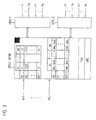
- an index table is provided in FIG. 2.
- the index table is used to transcode the signal transmitted via lines KI1 to KIn into an address for the tables with the safety parameters stored in the SPSR and SPST memories. Since different configurations of the machine tool can theoretically be signaled via lines KI1 to KIn, they do not occur in practice, however, and the same lines must be monitored by the processor CPU for different configurations, so there is no need for a line for each configuration K0 to K2 n -1 with information stored in the SPSR and SPST memories. This can save considerable space in the SPST and SPSR memories.
- the user changes the configuration of the machine tool by for example in a milling machine with pendulum machining in two work rooms the intermediate door between the two work rooms opens or this automatically through the numerical control of the milling machine is opened, then this is done by means of a detector for the operating state recognized and via one of the lines KI1 to KIn to the memory SPST and SPSR forwarded.
- a detector for the operating state recognized and via one of the lines KI1 to KIn to the memory SPST and SPSR forwarded.
- the two index tables for the protective doors and the shelters in the same SPST and SPSR stores as the associated ones Tables can then be saved, that is via the lines KI1 to KIn received output signal of the detector recoded in an address for the table of the door contact switches to be monitored and an address for the table with the maximum and minimum permitted actual positions of the axes A1 to Ak.
- the respective address is in the associated
- the table for this uses the line assigned to the configuration with the one there read out saved security parameters.
- the two lines include Information about the door contact switches to be monitored and the maximum permissible actual positions of the in a safe operating state Axes. This information is sent to the processor CPU for control of surveillance. It is now processed by the processor CPU the output signals of the newly transmitted door contact switches T1 to Tm, which on the identically labeled lines T1 to Tm to the Processor CPU are transferred, and the new actual positions are monitored.
- the two memories SPST and SPSR for the tables with the safety parameters can be formed as a single mass storage device, as in Fig. 3 shown, which the table with the door contact switches and the Table with the shelters for the different configurations included.
- the index tables for access can still be stored in this memory on the tables with the security parameters, a type identifier type of Machine tool and a checksum CRC can be stored.
- Advantageous is a realization of this mass storage as optical storage, magnetic or semiconductor memory.
- a magnetic memory can be used as a diskette, an optical one Storage as compact disk (CD) or digital versatile disk (DVD) for a numerical control of the machine tool can be designed if the numerical control also performs the monitoring functions.
- the optical memory, magnetic or semiconductor memory in Form of an interchangeable card designed for a corresponding reading device his.
- an identifier type is provided for the mass storage device, as in FIG. 3 shown, which is checked by at least one processor CPU. This The check can be carried out before each reading of security parameters from the Mass storage in the processor CPU. If the identifier of the Mass storage with the identifier stored in the processor CPU Type matches, an error message is issued to the user. Further information is then not read from the mass storage device and the axes of the machine tool are stopped. This is required because the configuration has changed, but the new security parameters are not available for monitoring. As an identifier Type can use, for example, a type identifier of the machine tool become.
- the table with the safety parameters also a checksum CRC, which changes when the security parameters change also changes.
- the checksum can be after Cyclic redundancy check method or another known method Procedures are generated. Immediately after a new memory SPST and / or SPSR has been connected to the machine or after safety parameters read out from at least one of the memories SPST or SPSR the checksum is checked by at least one processor CPU CRC recalculated and with the original one, in memory SPST or SPSR stored checksum CRC compared. There will be no match impermissible changes in the safety parameters are determined been made. In this case, a corresponding one Error handling performed by shutting down the machine and an error message regarding the mismatched checksum is issued.
- door contact switches as well as maximum and minimum actual positions of axes A1 to Ak other security parameters can also be stored in the tables compliance, at least with every new configuration of the Machine tool is checked.
- For redundant monitoring of the SPST memory in the tables and SPSR stored security parameters are either memory used by two processors, CPU1 and CPU2, as in Fig. 3, or it is CPU1 and CPU2 for each processor, respectively uses a memory, ensuring that the memories are the same Have memory content. Which depends on the configuration of the Machine tool from the two tables by the two processors CPU1 and CPU2 read out or to the two processors CPU1 and CPU2 transmitted security parameters are then in both processors CPU1 and CPU2 independently of each other with the over the lines T1 to Tm and P1 to Pk transferred to the two processors CPU1 and CPU2 compared the actual values of the safety parameters. Should only one of the two processors CPU1 or CPU2 an unsafe operating state the machine tool will recognize an error handling triggered.
- the identifiers type stored in the SPST and SPSR memories are in both processors CPU1 and CPU2 to match in assigned to the processors CPU1 and CPU2 or to these processors Save saved identifiers type checked.
Landscapes
- Engineering & Computer Science (AREA)
- Human Computer Interaction (AREA)
- Manufacturing & Machinery (AREA)
- Physics & Mathematics (AREA)
- General Physics & Mathematics (AREA)
- Automation & Control Theory (AREA)
- Numerical Control (AREA)
- Safety Devices In Control Systems (AREA)
Description
- Fig. 1:
- eine einfache Realisierungsform für das erfindungsgemäße Überwachungsverfahren,
- Fig. 2:
- die Realisierungsform aus Fig. 1 mit zusätzlichen Indextabellen und
- Fig. 3:
- die Realisierungsform aus Fig. 1 mit nur einem physikalischen Speicher und zwei Prozessoren.
Claims (14)
- Verfahren zur Auswahl von zu überwachenden Sicherheitsparametem einer Werkzeugmaschine oder eines Roboters, wobei für mögliche Konfigurationen (K0 - K2n-1) der Werkzeugmaschine oder des Roboters die zu überwachenden Sicherheitspararneter (T1 - Tn, P1 - Pk) in zumindest einem Speicher (SPST, SPSR) abgespeichert werden und die zu überwachenden Sicherheitsparameter (T1 - Tn, P1 - Pk) abhängig von der Konfiguration (K0 - K2n-1) der zu überwachenden Einrichtung zur Überwachung ausgewählt werden, indem Daten, die von Detektoren für die Konfiguration der zu überwachenden Einrichtung ausgegeben werden, entweder unmittelbar oder nach einer Umcodierung als Adresse für den zumindest einen Speicher (SPST, SPSR) der Sicherheitsparameter benutzt werden.
- Verfahren nach Anspruch 1, dadurch gekennzeichnet, daß aufgrund der Daten, welche die Konfiguration (K0 - K2n-1) der zu überwachenden Einrichtung kennzeichnen, aus dem zumindest einen Speicher (SPST, SPSR) die zu überwachenden Sicherheitsparameter (T1 - Tn, P1 - Pk) ausgelesen und an mindestens einen Prozessor (CPU) weitergeleitet werden.
- Verfahren nach Anspruch 1 oder 2, dadurch gekennzeichnet, daß durch mindestens einen Prozessor (CPU) bei der Überwachung ein sicheren Betriebszustands die von dem zumindest einen Speicher (SPST, SPSR) bereitgestellten Sicherheitsparameter (T1 - Tn, P1 - Pk) mit vorgegebenen Sollwerten verglichen werden.
- Verfahren nach einem der vorhergehenden Ansprüche, dadurch gekennzeichnet, daß die Umcodierung der Ausgangssignale der Detektoren für die Konfiguration der zu überwachenden Einrichtung in eine Adresse (TZ1 - TZr, TZ1 - TZs) für die Sicherheitsparameter (T1 - Tn, P1 - Pk) durch eine oder mehrere in dem zumindest einen Speicher (SPST, SPSR) abgelegte Indextabellen erfolgt.
- Verfahren nach einem der vorhergehenden Ansprüche, dadurch gekennzeichnet, daß vor dem Einlesen von neuen Sicherheitsparametern (T1 - Tm, P1 - Pk) durch mindestens einen Prozessor (CPU) eine Kennung (Typ) der Speicher (SPST, SPSR) überprüft wird und bei fehlerhafter Kennung (Typ) der Betrieb der Einrichtung angehalten wird.
- Verfahren nach einem der vorhergehenden Ansprüche, dadurch gekennzeichnet, daß nach dem Verbinden mindestens eines neuen Speichers (SPST, SPSR) oder nach dem Einlesen von neuen Sicherheitsparametern eine Prüfsumme (CRC) durch mindestens einen Prozessor (CPU) bezüglich des Speicherinhalts des neuen oder des neu ausgelesenen Speichers neu berechnet wird, daß diese Prüfsumme (CRC) mit einer in dem Speicher gespeicherten Prüfsumme (CRC) verglichen wird und daß bei fehlender Gleichheit der neu berechneten mit der gespeicherten Prüfsumme (CRC) der Betrieb der Einrichtung angehalten wird.
- Verfahren nach einem der vorhergehenden Ansprüche, dadurch gekennzeichnet, daß zwei Prozessoren (CPU1, CPU2) vorgesehen sind, die unabhängig voneinander das Verfahren durchführen, daß die in beiden Prozessoren (CPU1, CPU2) unabhängig voneinander ermittelten Ergebnisse auf Gleichheit überprüft werden und daß bei Ungleichheit der Betrieb angehalten, ansonsten weitergeführt wird.
- Verfahren nach einem der vorhergehenden Ansprüche, dadurch gekennzeichnet, daß als zu überwachende Sicherheitsparameter bestimmte Türkontaktschalter für einzelne Achsen (A1 bis Ak) abgespeichert sind, wobei durch eine Tabelle jeder Achse (A1 bis Ak) die Türkontaktschalter zugeordnet werden, deren zugehörige Schutztür für einen sicheren Betriebszustand geschlossen sein müssen.
- Verfahren nach einem der vorhergehenden Ansprüche, dadurch gekennzeichnet, daß als zu überwachende Sicherheitsparameter ein maximaler und minimaler Positionswert für einzelne Achsen (A1 bis Ak) abgespeichert sind, wobei durch eine Tabelle jeder Achse (A1 bis Ak) die Positionen der Achse (A1 bis Ak) für einen sicheren Betriebszustand zugeordnet werden.
- Anordnung zur Auswahl von zu überwachenden Sicherheitsparametern einer Werkzeugmaschine oder eines Roboters, wobei mindestens ein Prozessor (CPU), welcher die Überwachung durchführt, über Leitungen (T1 - Tm, P1 - Pk) mit Detektoren für die Betriebssicherheit der zu überwachenden Einrichtung verbunden ist, und der mindestens eine Prozessor (CPU) weiterhin mit mindestens einem Speicher (SPST, SPSR) verbunden ist, in welchem die zu überwachenden Sicherheitsparameter (T1 - Tm, P1 - Pk) für mögliche Konfigurationen der Werkzeugmaschine oder des Roboters gespeichert sind, und daß der zumindest eine Speicher (SPST, SPSR) über Leitungen (KI1 - KIn) mit Detektoren für die Konfiguration der zu überwachenden Einrichtung verbunden ist, an denen eine konfigurationsspezifische Adresse zur Adressierung des Speichers (SPST, SPSR) ansteht.
- Anordnung nach Anspruch 10, dadurch gekennzeichnet, daß der mindestens eine Speicher (SPST, SPSR) als auswechselbarer Speicher ausgestaltet ist.
- Anordnung nach Anspruch 10 oder 11, dadurch gekennzeichnet, daß der mindestens eine Speicher (SPST, SPSR) als optischer Speicher, Magnetoder Halbleiterspeicher ausgestaltet ist.
- Anordnung nach einem der Ansprüche 10 bis 12, dadurch gekennzeichnet, daß der mindestens eine Speicher (SPST, SPSR) eine Kennung beinhaltet.
- Anordnung nach einem der Ansprüche 10 bis 13, dadurch gekennzeichnet, daß zwei Prozessoren (CPU1, CPU2) vorgesehen sind, die mit den Detektoren und mit den mindestens einem Speicher (SPST, SPSR) verbunden sind, wodurch zwei Prozessoren (CPU1, CPU2) unabhängig voneinander die Sicherheitseinrichtungen überwachen.
Applications Claiming Priority (3)
| Application Number | Priority Date | Filing Date | Title |
|---|---|---|---|
| DE19818181A DE19818181A1 (de) | 1998-04-23 | 1998-04-23 | Verfahren und Anordnung zur Auswahl von zu überwachenden Sicherheitsparametern |
| DE19818181 | 1998-04-23 | ||
| PCT/EP1999/002007 WO1999056187A1 (de) | 1998-04-23 | 1999-03-24 | Verfahren und anordnung zur auswahl von zu überwachenden sicherheitsparametern |
Publications (2)
| Publication Number | Publication Date |
|---|---|
| EP1073938A1 EP1073938A1 (de) | 2001-02-07 |
| EP1073938B1 true EP1073938B1 (de) | 2002-10-23 |
Family
ID=7865576
Family Applications (1)
| Application Number | Title | Priority Date | Filing Date |
|---|---|---|---|
| EP99914536A Expired - Lifetime EP1073938B1 (de) | 1998-04-23 | 1999-03-24 | Verfahren und anordnung zur auswahl von zu überwachenden sicherheitsparametern |
Country Status (5)
| Country | Link |
|---|---|
| US (1) | US6445965B1 (de) |
| EP (1) | EP1073938B1 (de) |
| JP (1) | JP2002513177A (de) |
| DE (2) | DE19818181A1 (de) |
| WO (1) | WO1999056187A1 (de) |
Families Citing this family (3)
| Publication number | Priority date | Publication date | Assignee | Title |
|---|---|---|---|---|
| DE102012016406B4 (de) | 2012-08-21 | 2014-12-24 | Krohne Messtechnik Gmbh | Verfahren zur Parametrierung eines Feldgerätes und entsprechendes System zur Parametrierung |
| DE102018206109B4 (de) * | 2018-04-20 | 2021-01-07 | Lenze Automation Gmbh | Elektrisches Steuergerät und Steuergerätesystem |
| EP3598254B1 (de) * | 2018-07-17 | 2021-03-31 | Siemens Aktiengesellschaft | Verfahren zur konfigurationsänderung und industrielles anlagensystem |
Family Cites Families (16)
| Publication number | Priority date | Publication date | Assignee | Title |
|---|---|---|---|---|
| US4977529A (en) * | 1973-02-23 | 1990-12-11 | Westinghouse Electric Corp. | Training simulator for a nuclear power plant |
| DE2903978A1 (de) * | 1979-02-02 | 1980-08-07 | Bosch Gmbh Robert | Einrichtung zum steuern von betriebsparameterabhaengigen vorgaengen, insbesondere des schliesszeitbeginns fuer zuendanlagen von brennkraftmaschinen |
| EP0130179A1 (de) * | 1982-12-23 | 1985-01-09 | Dst Digitale Steuerungssysteme Gmbh | Verfahren und vorrichtung zur überwachung von prozessen |
| US4791569A (en) * | 1985-03-18 | 1988-12-13 | Honda Giken Kogyo Kabushiki Kaisha | Electronic control system for internal combustion engines |
| DE3610620C2 (de) * | 1986-03-29 | 1996-03-28 | Teves Gmbh Alfred | Programmgesteuerter elektronischer Regler |
| DE3733832A1 (de) * | 1987-10-07 | 1989-04-27 | Messerschmitt Boelkow Blohm | Sensor fuer kraftfahrzeuge |
| DE4000295C2 (de) * | 1990-01-08 | 1994-05-19 | Heidelberger Druckmasch Ag | Vorrichtung zur Diagnose eines Steuersystems einer Druckmaschine |
| US5353238A (en) * | 1991-09-12 | 1994-10-04 | Cloos International Inc. | Welding robot diagnostic system and method of use thereof |
| DE4140693A1 (de) * | 1991-12-10 | 1993-06-17 | Bayerische Motoren Werke Ag | Elektronisches steuergeraet mit mehreren darin abgelegten datensaetzen und/oder datensatzteilen |
| DE4207705C1 (de) * | 1992-03-11 | 1993-04-29 | Dorma Gmbh + Co. Kg, 5828 Ennepetal, De | |
| DE4213171A1 (de) * | 1992-04-22 | 1993-10-28 | Jossi Hans Praezisionsmechanik | Sicherheitsschaltung |
| DE4341082A1 (de) * | 1993-12-02 | 1995-06-08 | Teves Gmbh Alfred | Schaltungsanordnung für sicherheitskritische Regelungssysteme |
| DE4342903A1 (de) * | 1993-12-16 | 1995-06-22 | Bosch Gmbh Robert | Vorrichtung zum Überwachen wenigstens einer sicherheitsrelevanten Funktion eines Gerätes |
| DE19529891A1 (de) * | 1995-08-14 | 1997-02-20 | Lenz & Wolf Steuerungssysteme | Digitale Peripherieeinrichtung für speicherprogrammierbare Maschinensteuerungen |
| US5666010A (en) * | 1995-08-30 | 1997-09-09 | Stratiotis; Gus | Safety system for machine tools |
| DE29706969U1 (de) * | 1996-05-03 | 1997-07-17 | Inventio Ag, Hergiswil, Nidwalden | Vorrichtung für die Sicherung von System-Konfigurationsdaten |
-
1998
- 1998-04-23 DE DE19818181A patent/DE19818181A1/de not_active Withdrawn
-
1999
- 1999-03-24 WO PCT/EP1999/002007 patent/WO1999056187A1/de not_active Ceased
- 1999-03-24 JP JP2000546286A patent/JP2002513177A/ja active Pending
- 1999-03-24 DE DE59903175T patent/DE59903175D1/de not_active Expired - Lifetime
- 1999-03-24 EP EP99914536A patent/EP1073938B1/de not_active Expired - Lifetime
- 1999-04-23 US US09/298,658 patent/US6445965B1/en not_active Expired - Fee Related
Also Published As
| Publication number | Publication date |
|---|---|
| WO1999056187A1 (de) | 1999-11-04 |
| DE19818181A1 (de) | 1999-10-28 |
| JP2002513177A (ja) | 2002-05-08 |
| US6445965B1 (en) | 2002-09-03 |
| EP1073938A1 (de) | 2001-02-07 |
| DE59903175D1 (de) | 2002-11-28 |
Similar Documents
| Publication | Publication Date | Title |
|---|---|---|
| DE19927635B4 (de) | Sicherheitsbezogenes Automatisierungsbussystem | |
| DE19742716C5 (de) | Steuer- und Datenübertragungsanlage und Verfahren zum Übertragen von sicherheitsbezogenen Daten | |
| EP0906596B1 (de) | Prozessautomatisierungssystem | |
| EP1188096B2 (de) | Steuerungssystem zum steuern von sicherheitskritischen prozessen | |
| EP3069202B1 (de) | Sicherheitssteuerung mit konfigurierbaren eingängen | |
| EP1362269A2 (de) | Verfahren und vorrichtung zum programmieren einer sicherheitssteuerung | |
| EP0723243B1 (de) | Vorrichtung und Verfahren zur Bearbeitung von dünnem Blattgut, wie z.B. Banknoten | |
| WO2010060575A1 (de) | Verfahren und vorrichtung zum erstellen eines anwenderprogramms für eine sicherheitssteuerung | |
| EP1328853A2 (de) | Verfahren, einrichtung und system zum erfassen, visualisieren und/oder zum verändern von betriebsdaten wenigstens einer maschine der tabakverarbeitenden industrie | |
| EP4020103B1 (de) | Verfahren und industrieanlage zum verwalten und steuern von produktionsmitteln | |
| EP1043641A2 (de) | Fehlersicheres Automatisierungssystem mit Standard-CPU und Verfahren für ein fehlersicheres Automatisierungssystem | |
| EP1811722A2 (de) | Verfahren und Vorrichtung zur Umwandlung mehrkanalig vorliegender Nachrichten in eine einkanalige sichere Nachricht | |
| DE29907909U1 (de) | Einsteckkarte und integriertes Überwachungssystem für Prozesse | |
| DE102007063291A1 (de) | Sicherheitssteuerung | |
| EP3706962B1 (de) | Redundante diversitäre kollisionsüberwachung | |
| DE102009019096A1 (de) | Sicherheitssteuerung und Verfahren zum Steuern einer automatisierten Anlage | |
| EP0436818B1 (de) | Diagnosesystem für eine digitale Steuereinrichtung | |
| WO1999056187A1 (de) | Verfahren und anordnung zur auswahl von zu überwachenden sicherheitsparametern | |
| DE102009041781A1 (de) | Bereitstellung anlagenbezogener Betriebsdaten unter Verwendung eines Diagnose-Datenservers als weiteren Feldbusmaster | |
| EP1353246B1 (de) | Sicherheitsschalteranordnung | |
| EP1485765A2 (de) | Sensor-maschinen-interface und verfahren zu dessen betrieb | |
| DE102006012042A1 (de) | Steuervorrichtung zur fehlersicheren Steuerung einer Maschine | |
| EP4089312A1 (de) | Sicherheitseinrichtung und verfahren zum betrieb einer sicherheitseinrichtung | |
| EP2246761B1 (de) | Verfahren zum sicheren Ändern von Parametern einer fehlersicheren industriellen Automatisierungskomponente | |
| DE3311805A1 (de) | Speicherprogrammierbare steuerung |
Legal Events
| Date | Code | Title | Description |
|---|---|---|---|
| PUAI | Public reference made under article 153(3) epc to a published international application that has entered the european phase |
Free format text: ORIGINAL CODE: 0009012 |
|
| 17P | Request for examination filed |
Effective date: 20001123 |
|
| AK | Designated contracting states |
Kind code of ref document: A1 Designated state(s): CH DE FR GB IT LI |
|
| GRAG | Despatch of communication of intention to grant |
Free format text: ORIGINAL CODE: EPIDOS AGRA |
|
| GRAG | Despatch of communication of intention to grant |
Free format text: ORIGINAL CODE: EPIDOS AGRA |
|
| GRAH | Despatch of communication of intention to grant a patent |
Free format text: ORIGINAL CODE: EPIDOS IGRA |
|
| 17Q | First examination report despatched |
Effective date: 20020507 |
|
| GRAH | Despatch of communication of intention to grant a patent |
Free format text: ORIGINAL CODE: EPIDOS IGRA |
|
| GRAA | (expected) grant |
Free format text: ORIGINAL CODE: 0009210 |
|
| AK | Designated contracting states |
Kind code of ref document: B1 Designated state(s): CH DE FR GB IT LI |
|
| REG | Reference to a national code |
Ref country code: GB Ref legal event code: FG4D Free format text: NOT ENGLISH |
|
| REG | Reference to a national code |
Ref country code: CH Ref legal event code: EP |
|
| REG | Reference to a national code |
Ref country code: CH Ref legal event code: NV Representative=s name: TROESCH SCHEIDEGGER WERNER AG |
|
| REF | Corresponds to: |
Ref document number: 59903175 Country of ref document: DE Date of ref document: 20021128 |
|
| GBT | Gb: translation of ep patent filed (gb section 77(6)(a)/1977) |
Effective date: 20030127 |
|
| ET | Fr: translation filed | ||
| PLBE | No opposition filed within time limit |
Free format text: ORIGINAL CODE: 0009261 |
|
| STAA | Information on the status of an ep patent application or granted ep patent |
Free format text: STATUS: NO OPPOSITION FILED WITHIN TIME LIMIT |
|
| 26N | No opposition filed |
Effective date: 20030724 |
|
| PGFP | Annual fee paid to national office [announced via postgrant information from national office to epo] |
Ref country code: CH Payment date: 20140319 Year of fee payment: 16 |
|
| PGFP | Annual fee paid to national office [announced via postgrant information from national office to epo] |
Ref country code: FR Payment date: 20140319 Year of fee payment: 16 Ref country code: IT Payment date: 20140327 Year of fee payment: 16 |
|
| PGFP | Annual fee paid to national office [announced via postgrant information from national office to epo] |
Ref country code: GB Payment date: 20140319 Year of fee payment: 16 |
|
| REG | Reference to a national code |
Ref country code: CH Ref legal event code: PL |
|
| GBPC | Gb: european patent ceased through non-payment of renewal fee |
Effective date: 20150324 |
|
| PG25 | Lapsed in a contracting state [announced via postgrant information from national office to epo] |
Ref country code: IT Free format text: LAPSE BECAUSE OF NON-PAYMENT OF DUE FEES Effective date: 20150324 |
|
| REG | Reference to a national code |
Ref country code: FR Ref legal event code: ST Effective date: 20151130 |
|
| PG25 | Lapsed in a contracting state [announced via postgrant information from national office to epo] |
Ref country code: CH Free format text: LAPSE BECAUSE OF NON-PAYMENT OF DUE FEES Effective date: 20150331 Ref country code: LI Free format text: LAPSE BECAUSE OF NON-PAYMENT OF DUE FEES Effective date: 20150331 Ref country code: GB Free format text: LAPSE BECAUSE OF NON-PAYMENT OF DUE FEES Effective date: 20150324 |
|
| PG25 | Lapsed in a contracting state [announced via postgrant information from national office to epo] |
Ref country code: FR Free format text: LAPSE BECAUSE OF NON-PAYMENT OF DUE FEES Effective date: 20150331 |
|
| PGFP | Annual fee paid to national office [announced via postgrant information from national office to epo] |
Ref country code: DE Payment date: 20170322 Year of fee payment: 19 |
|
| REG | Reference to a national code |
Ref country code: DE Ref legal event code: R119 Ref document number: 59903175 Country of ref document: DE |
|
| PG25 | Lapsed in a contracting state [announced via postgrant information from national office to epo] |
Ref country code: DE Free format text: LAPSE BECAUSE OF NON-PAYMENT OF DUE FEES Effective date: 20181002 |