EP1073831B1 - Catalytic gas treatment device - Google Patents
Catalytic gas treatment device Download PDFInfo
- Publication number
- EP1073831B1 EP1073831B1 EP99905393A EP99905393A EP1073831B1 EP 1073831 B1 EP1073831 B1 EP 1073831B1 EP 99905393 A EP99905393 A EP 99905393A EP 99905393 A EP99905393 A EP 99905393A EP 1073831 B1 EP1073831 B1 EP 1073831B1
- Authority
- EP
- European Patent Office
- Prior art keywords
- gas
- band
- package
- catalytic treatment
- catalyst
- Prior art date
- Legal status (The legal status is an assumption and is not a legal conclusion. Google has not performed a legal analysis and makes no representation as to the accuracy of the status listed.)
- Expired - Lifetime
Links
Images
Classifications
-
- F—MECHANICAL ENGINEERING; LIGHTING; HEATING; WEAPONS; BLASTING
- F01—MACHINES OR ENGINES IN GENERAL; ENGINE PLANTS IN GENERAL; STEAM ENGINES
- F01N—GAS-FLOW SILENCERS OR EXHAUST APPARATUS FOR MACHINES OR ENGINES IN GENERAL; GAS-FLOW SILENCERS OR EXHAUST APPARATUS FOR INTERNAL COMBUSTION ENGINES
- F01N3/00—Exhaust or silencing apparatus having means for purifying, rendering innocuous, or otherwise treating exhaust
- F01N3/08—Exhaust or silencing apparatus having means for purifying, rendering innocuous, or otherwise treating exhaust for rendering innocuous
- F01N3/10—Exhaust or silencing apparatus having means for purifying, rendering innocuous, or otherwise treating exhaust for rendering innocuous by thermal or catalytic conversion of noxious components of exhaust
- F01N3/24—Exhaust or silencing apparatus having means for purifying, rendering innocuous, or otherwise treating exhaust for rendering innocuous by thermal or catalytic conversion of noxious components of exhaust characterised by constructional aspects of converting apparatus
- F01N3/28—Construction of catalytic reactors
-
- F—MECHANICAL ENGINEERING; LIGHTING; HEATING; WEAPONS; BLASTING
- F23—COMBUSTION APPARATUS; COMBUSTION PROCESSES
- F23G—CREMATION FURNACES; CONSUMING WASTE PRODUCTS BY COMBUSTION
- F23G7/00—Incinerators or other apparatus for consuming industrial waste, e.g. chemicals
- F23G7/06—Incinerators or other apparatus for consuming industrial waste, e.g. chemicals of waste gases or noxious gases, e.g. exhaust gases
- F23G7/07—Incinerators or other apparatus for consuming industrial waste, e.g. chemicals of waste gases or noxious gases, e.g. exhaust gases in which combustion takes place in the presence of catalytic material
-
- F—MECHANICAL ENGINEERING; LIGHTING; HEATING; WEAPONS; BLASTING
- F01—MACHINES OR ENGINES IN GENERAL; ENGINE PLANTS IN GENERAL; STEAM ENGINES
- F01N—GAS-FLOW SILENCERS OR EXHAUST APPARATUS FOR MACHINES OR ENGINES IN GENERAL; GAS-FLOW SILENCERS OR EXHAUST APPARATUS FOR INTERNAL COMBUSTION ENGINES
- F01N13/00—Exhaust or silencing apparatus characterised by constructional features ; Exhaust or silencing apparatus, or parts thereof, having pertinent characteristics not provided for in, or of interest apart from, groups F01N1/00 - F01N5/00, F01N9/00, F01N11/00
- F01N13/009—Exhaust or silencing apparatus characterised by constructional features ; Exhaust or silencing apparatus, or parts thereof, having pertinent characteristics not provided for in, or of interest apart from, groups F01N1/00 - F01N5/00, F01N9/00, F01N11/00 having two or more separate purifying devices arranged in series
- F01N13/0097—Exhaust or silencing apparatus characterised by constructional features ; Exhaust or silencing apparatus, or parts thereof, having pertinent characteristics not provided for in, or of interest apart from, groups F01N1/00 - F01N5/00, F01N9/00, F01N11/00 having two or more separate purifying devices arranged in series the purifying devices are arranged in a single housing
-
- F—MECHANICAL ENGINEERING; LIGHTING; HEATING; WEAPONS; BLASTING
- F01—MACHINES OR ENGINES IN GENERAL; ENGINE PLANTS IN GENERAL; STEAM ENGINES
- F01N—GAS-FLOW SILENCERS OR EXHAUST APPARATUS FOR MACHINES OR ENGINES IN GENERAL; GAS-FLOW SILENCERS OR EXHAUST APPARATUS FOR INTERNAL COMBUSTION ENGINES
- F01N13/00—Exhaust or silencing apparatus characterised by constructional features ; Exhaust or silencing apparatus, or parts thereof, having pertinent characteristics not provided for in, or of interest apart from, groups F01N1/00 - F01N5/00, F01N9/00, F01N11/00
- F01N13/18—Construction facilitating manufacture, assembly, or disassembly
- F01N13/1805—Fixing exhaust manifolds, exhaust pipes or pipe sections to each other, to engine or to vehicle body
- F01N13/1827—Sealings specially adapted for exhaust systems
-
- F—MECHANICAL ENGINEERING; LIGHTING; HEATING; WEAPONS; BLASTING
- F01—MACHINES OR ENGINES IN GENERAL; ENGINE PLANTS IN GENERAL; STEAM ENGINES
- F01N—GAS-FLOW SILENCERS OR EXHAUST APPARATUS FOR MACHINES OR ENGINES IN GENERAL; GAS-FLOW SILENCERS OR EXHAUST APPARATUS FOR INTERNAL COMBUSTION ENGINES
- F01N3/00—Exhaust or silencing apparatus having means for purifying, rendering innocuous, or otherwise treating exhaust
- F01N3/08—Exhaust or silencing apparatus having means for purifying, rendering innocuous, or otherwise treating exhaust for rendering innocuous
- F01N3/10—Exhaust or silencing apparatus having means for purifying, rendering innocuous, or otherwise treating exhaust for rendering innocuous by thermal or catalytic conversion of noxious components of exhaust
- F01N3/18—Exhaust or silencing apparatus having means for purifying, rendering innocuous, or otherwise treating exhaust for rendering innocuous by thermal or catalytic conversion of noxious components of exhaust characterised by methods of operation; Control
- F01N3/20—Exhaust or silencing apparatus having means for purifying, rendering innocuous, or otherwise treating exhaust for rendering innocuous by thermal or catalytic conversion of noxious components of exhaust characterised by methods of operation; Control specially adapted for catalytic conversion ; Methods of operation or control of catalytic converters
- F01N3/2006—Periodically heating or cooling catalytic reactors, e.g. at cold starting or overheating
- F01N3/2013—Periodically heating or cooling catalytic reactors, e.g. at cold starting or overheating using electric or magnetic heating means
-
- F—MECHANICAL ENGINEERING; LIGHTING; HEATING; WEAPONS; BLASTING
- F01—MACHINES OR ENGINES IN GENERAL; ENGINE PLANTS IN GENERAL; STEAM ENGINES
- F01N—GAS-FLOW SILENCERS OR EXHAUST APPARATUS FOR MACHINES OR ENGINES IN GENERAL; GAS-FLOW SILENCERS OR EXHAUST APPARATUS FOR INTERNAL COMBUSTION ENGINES
- F01N3/00—Exhaust or silencing apparatus having means for purifying, rendering innocuous, or otherwise treating exhaust
- F01N3/08—Exhaust or silencing apparatus having means for purifying, rendering innocuous, or otherwise treating exhaust for rendering innocuous
- F01N3/10—Exhaust or silencing apparatus having means for purifying, rendering innocuous, or otherwise treating exhaust for rendering innocuous by thermal or catalytic conversion of noxious components of exhaust
- F01N3/18—Exhaust or silencing apparatus having means for purifying, rendering innocuous, or otherwise treating exhaust for rendering innocuous by thermal or catalytic conversion of noxious components of exhaust characterised by methods of operation; Control
- F01N3/20—Exhaust or silencing apparatus having means for purifying, rendering innocuous, or otherwise treating exhaust for rendering innocuous by thermal or catalytic conversion of noxious components of exhaust characterised by methods of operation; Control specially adapted for catalytic conversion ; Methods of operation or control of catalytic converters
- F01N3/2006—Periodically heating or cooling catalytic reactors, e.g. at cold starting or overheating
- F01N3/2033—Periodically heating or cooling catalytic reactors, e.g. at cold starting or overheating using a fuel burner or introducing fuel into exhaust duct
-
- F—MECHANICAL ENGINEERING; LIGHTING; HEATING; WEAPONS; BLASTING
- F01—MACHINES OR ENGINES IN GENERAL; ENGINE PLANTS IN GENERAL; STEAM ENGINES
- F01N—GAS-FLOW SILENCERS OR EXHAUST APPARATUS FOR MACHINES OR ENGINES IN GENERAL; GAS-FLOW SILENCERS OR EXHAUST APPARATUS FOR INTERNAL COMBUSTION ENGINES
- F01N3/00—Exhaust or silencing apparatus having means for purifying, rendering innocuous, or otherwise treating exhaust
- F01N3/08—Exhaust or silencing apparatus having means for purifying, rendering innocuous, or otherwise treating exhaust for rendering innocuous
- F01N3/10—Exhaust or silencing apparatus having means for purifying, rendering innocuous, or otherwise treating exhaust for rendering innocuous by thermal or catalytic conversion of noxious components of exhaust
- F01N3/18—Exhaust or silencing apparatus having means for purifying, rendering innocuous, or otherwise treating exhaust for rendering innocuous by thermal or catalytic conversion of noxious components of exhaust characterised by methods of operation; Control
- F01N3/20—Exhaust or silencing apparatus having means for purifying, rendering innocuous, or otherwise treating exhaust for rendering innocuous by thermal or catalytic conversion of noxious components of exhaust characterised by methods of operation; Control specially adapted for catalytic conversion ; Methods of operation or control of catalytic converters
- F01N3/2006—Periodically heating or cooling catalytic reactors, e.g. at cold starting or overheating
- F01N3/2046—Periodically cooling catalytic reactors
-
- F—MECHANICAL ENGINEERING; LIGHTING; HEATING; WEAPONS; BLASTING
- F01—MACHINES OR ENGINES IN GENERAL; ENGINE PLANTS IN GENERAL; STEAM ENGINES
- F01N—GAS-FLOW SILENCERS OR EXHAUST APPARATUS FOR MACHINES OR ENGINES IN GENERAL; GAS-FLOW SILENCERS OR EXHAUST APPARATUS FOR INTERNAL COMBUSTION ENGINES
- F01N3/00—Exhaust or silencing apparatus having means for purifying, rendering innocuous, or otherwise treating exhaust
- F01N3/08—Exhaust or silencing apparatus having means for purifying, rendering innocuous, or otherwise treating exhaust for rendering innocuous
- F01N3/10—Exhaust or silencing apparatus having means for purifying, rendering innocuous, or otherwise treating exhaust for rendering innocuous by thermal or catalytic conversion of noxious components of exhaust
- F01N3/24—Exhaust or silencing apparatus having means for purifying, rendering innocuous, or otherwise treating exhaust for rendering innocuous by thermal or catalytic conversion of noxious components of exhaust characterised by constructional aspects of converting apparatus
- F01N3/28—Construction of catalytic reactors
- F01N3/2803—Construction of catalytic reactors characterised by structure, by material or by manufacturing of catalyst support
- F01N3/2807—Metal other than sintered metal
-
- F—MECHANICAL ENGINEERING; LIGHTING; HEATING; WEAPONS; BLASTING
- F01—MACHINES OR ENGINES IN GENERAL; ENGINE PLANTS IN GENERAL; STEAM ENGINES
- F01N—GAS-FLOW SILENCERS OR EXHAUST APPARATUS FOR MACHINES OR ENGINES IN GENERAL; GAS-FLOW SILENCERS OR EXHAUST APPARATUS FOR INTERNAL COMBUSTION ENGINES
- F01N3/00—Exhaust or silencing apparatus having means for purifying, rendering innocuous, or otherwise treating exhaust
- F01N3/08—Exhaust or silencing apparatus having means for purifying, rendering innocuous, or otherwise treating exhaust for rendering innocuous
- F01N3/10—Exhaust or silencing apparatus having means for purifying, rendering innocuous, or otherwise treating exhaust for rendering innocuous by thermal or catalytic conversion of noxious components of exhaust
- F01N3/24—Exhaust or silencing apparatus having means for purifying, rendering innocuous, or otherwise treating exhaust for rendering innocuous by thermal or catalytic conversion of noxious components of exhaust characterised by constructional aspects of converting apparatus
- F01N3/28—Construction of catalytic reactors
- F01N3/2882—Catalytic reactors combined or associated with other devices, e.g. exhaust silencers or other exhaust purification devices
- F01N3/2889—Catalytic reactors combined or associated with other devices, e.g. exhaust silencers or other exhaust purification devices with heat exchangers in a single housing
-
- F—MECHANICAL ENGINEERING; LIGHTING; HEATING; WEAPONS; BLASTING
- F01—MACHINES OR ENGINES IN GENERAL; ENGINE PLANTS IN GENERAL; STEAM ENGINES
- F01N—GAS-FLOW SILENCERS OR EXHAUST APPARATUS FOR MACHINES OR ENGINES IN GENERAL; GAS-FLOW SILENCERS OR EXHAUST APPARATUS FOR INTERNAL COMBUSTION ENGINES
- F01N2240/00—Combination or association of two or more different exhaust treating devices, or of at least one such device with an auxiliary device, not covered by indexing codes F01N2230/00 or F01N2250/00, one of the devices being
- F01N2240/02—Combination or association of two or more different exhaust treating devices, or of at least one such device with an auxiliary device, not covered by indexing codes F01N2230/00 or F01N2250/00, one of the devices being a heat exchanger
-
- F—MECHANICAL ENGINEERING; LIGHTING; HEATING; WEAPONS; BLASTING
- F01—MACHINES OR ENGINES IN GENERAL; ENGINE PLANTS IN GENERAL; STEAM ENGINES
- F01N—GAS-FLOW SILENCERS OR EXHAUST APPARATUS FOR MACHINES OR ENGINES IN GENERAL; GAS-FLOW SILENCERS OR EXHAUST APPARATUS FOR INTERNAL COMBUSTION ENGINES
- F01N2260/00—Exhaust treating devices having provisions not otherwise provided for
- F01N2260/02—Exhaust treating devices having provisions not otherwise provided for for cooling the device
- F01N2260/022—Exhaust treating devices having provisions not otherwise provided for for cooling the device using air
-
- F—MECHANICAL ENGINEERING; LIGHTING; HEATING; WEAPONS; BLASTING
- F01—MACHINES OR ENGINES IN GENERAL; ENGINE PLANTS IN GENERAL; STEAM ENGINES
- F01N—GAS-FLOW SILENCERS OR EXHAUST APPARATUS FOR MACHINES OR ENGINES IN GENERAL; GAS-FLOW SILENCERS OR EXHAUST APPARATUS FOR INTERNAL COMBUSTION ENGINES
- F01N2270/00—Mixing air with exhaust gases
- F01N2270/02—Mixing air with exhaust gases for cooling exhaust gases or the apparatus
-
- F—MECHANICAL ENGINEERING; LIGHTING; HEATING; WEAPONS; BLASTING
- F01—MACHINES OR ENGINES IN GENERAL; ENGINE PLANTS IN GENERAL; STEAM ENGINES
- F01N—GAS-FLOW SILENCERS OR EXHAUST APPARATUS FOR MACHINES OR ENGINES IN GENERAL; GAS-FLOW SILENCERS OR EXHAUST APPARATUS FOR INTERNAL COMBUSTION ENGINES
- F01N2470/00—Structure or shape of gas passages, pipes or tubes
- F01N2470/18—Structure or shape of gas passages, pipes or tubes the axis of inlet or outlet tubes being other than the longitudinal axis of apparatus
-
- F—MECHANICAL ENGINEERING; LIGHTING; HEATING; WEAPONS; BLASTING
- F01—MACHINES OR ENGINES IN GENERAL; ENGINE PLANTS IN GENERAL; STEAM ENGINES
- F01N—GAS-FLOW SILENCERS OR EXHAUST APPARATUS FOR MACHINES OR ENGINES IN GENERAL; GAS-FLOW SILENCERS OR EXHAUST APPARATUS FOR INTERNAL COMBUSTION ENGINES
- F01N2510/00—Surface coverings
- F01N2510/06—Surface coverings for exhaust purification, e.g. catalytic reaction
-
- Y—GENERAL TAGGING OF NEW TECHNOLOGICAL DEVELOPMENTS; GENERAL TAGGING OF CROSS-SECTIONAL TECHNOLOGIES SPANNING OVER SEVERAL SECTIONS OF THE IPC; TECHNICAL SUBJECTS COVERED BY FORMER USPC CROSS-REFERENCE ART COLLECTIONS [XRACs] AND DIGESTS
- Y02—TECHNOLOGIES OR APPLICATIONS FOR MITIGATION OR ADAPTATION AGAINST CLIMATE CHANGE
- Y02T—CLIMATE CHANGE MITIGATION TECHNOLOGIES RELATED TO TRANSPORTATION
- Y02T10/00—Road transport of goods or passengers
- Y02T10/10—Internal combustion engine [ICE] based vehicles
- Y02T10/12—Improving ICE efficiencies
Definitions
- the present invention relates to a catalytic gas-mixture treatment device of the kind defined in the preamble of the appended claim 1.
- the Swedish Patent No. 503 172 describes a catalytic device comprising a catalyst-coated, patterned band, which is folded into a package for the purpose of simultaneously achieving heat exchange and catalytic treatment of a flow of gas.
- the flow may be divided into several parallel part flows, which are again united into one single flow. This is effected by blowing the gas flow into and withdrawing it from the package at opposite package sides at one of the package ends.
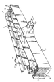
- FIG. 1 One embodiment of the invention is illustrated in the accompanying drawing figure.
- the drawing figure illustrates the inventive object in an unassembled condition and without the top of the casing 2.
- a package 1 of a patterned and folded band is received inside a casing 2.
- Gas enters through an inlet port 3, in the example shown centrally on one side of the band package.
- the gas flow divides into two oppositely directed part flows, each flowing towards its respective package end and the gas reversal chambers 4 and 5 located there.
- the gas may be heated by the heating elements 7 and 8, respectively, alternatively by hot gas or hot air supplied to the gas reversal chambers, and from these chambers the gas reverses, flowing along the opposite side of the band, towards the centre of the band package and exits through the outlet port 6.
- the band constituting the band package consequently serves both as a heat-exchange partition wall between the incoming and exiting flows and as a catalyst carrier.
- the heat-exchange process is made independent of the temperature of the incoming gas and the catalytic treatment may be carried out at an high temperature without considerable amounts of energy having to be supplied in the gas reversal chambers.
- cooling is effected by supply of cool air or gas to the gas reversal chambers 4, 5 or, alternatively, by means of refrigerating coils or refrigerating elements located therein.
- the major part of the band package will have a lower temperature than the incoming gas.
- a further advantage of the invention is that for a given width and height of the band package the pressure drop of the gas passing through the device is smaller than it would have been, had the entire gas flow been forced to pass through a package in one direction only.
- the design and arrangement of the temperature-modifying and temperature-controlling devices such as heating and/or refrigerating devices, that are located in the gas reversal chambers, may be altered in many different ways without departure from the inventive idea. Also, the devices in the two chambers may be of a mutually different nature.
Abstract
Description
- The present invention relates to a catalytic gas-mixture treatment device of the kind defined in the preamble of the appended claim 1.
- The Swedish Patent No. 503 172 describes a catalytic device comprising a catalyst-coated, patterned band, which is folded into a package for the purpose of simultaneously achieving heat exchange and catalytic treatment of a flow of gas. In the process, the flow may be divided into several parallel part flows, which are again united into one single flow. This is effected by blowing the gas flow into and withdrawing it from the package at opposite package sides at one of the package ends. There is no need for a separate gas-distributing device of manifold type and as long as the temperature is moderate, there is no difficulty in sealing the band-package end against the end wall of the enclosure or casing. Such sealing is necessary to prevent untreated gas from leaking past the heat exchange-catalyst unit.
- When the temperature of the entering gas is high, which sometimes is the case in the treatment of motor vehicle exhaust gases, it may be difficult to achieve efficient sealing of this kind. Conventional sealing materials or sealing compounds of rubber or plastics cannot withstand the high temperatures involved. A sheet of ceramic fibrous felt may be used as the seal along the sides of the band package, where considerable surfaces of contact exist. On the other hand, at the end walls, the seal is to be applied against the thin edges of the band, which makes efficient sealing much more difficult to achieve.
- In accordance with the present invention a solution to this sealing problem has been found according to the characterising portion of claim 1.
- One embodiment of the invention is illustrated in the accompanying drawing figure. For the sake of clarity, the drawing figure illustrates the inventive object in an unassembled condition and without the top of the casing 2. A package 1 of a patterned and folded band is received inside a casing 2. Gas enters through an inlet port 3, in the example shown centrally on one side of the band package. The gas flow divides into two oppositely directed part flows, each flowing towards its respective package end and the gas reversal chambers 4 and 5 located there. In the gas reversal chambers the gas may be heated by the heating elements 7 and 8, respectively, alternatively by hot gas or hot air supplied to the gas reversal chambers, and from these chambers the gas reverses, flowing along the opposite side of the band, towards the centre of the band package and exits through the outlet port 6.
- As the gas passes through the device, recuperative exchange of heat takes place via the band material between gas on its way to and gas on its way from, respectively, the gas reversal chambers. The band constituting the band package consequently serves both as a heat-exchange partition wall between the incoming and exiting flows and as a catalyst carrier. In this manner, the heat-exchange process is made independent of the temperature of the incoming gas and the catalytic treatment may be carried out at an high temperature without considerable amounts of energy having to be supplied in the gas reversal chambers.
- Owing to the division of the incoming flow into two part flows, one to each gas reversal chamber 4, 5, sealing against the end walls is not necessary. The only seals needed are the seal positioned between the bottom face of the package 1 and the casing bottom (not shown in the drawing figure) and the
seal 9 required between the upper face of the package 1 and the casing top, not included in the drawing figure. Owing to the considerable surface of contact, these seals may both consist of ceramic fibrous felt. No sealing is required at the two package ends and the gas reversal chambers 4, 5. This feature makes the inventive device highly suitable for treatment of gas entering the device at a high temperature. In some cases, for example to prevent damage to the catalyst coating, it may be necessary to cool the gas in the gas reversal chambers rather than heating it. Advantageously, cooling is effected by supply of cool air or gas to the gas reversal chambers 4, 5 or, alternatively, by means of refrigerating coils or refrigerating elements located therein. As a result of the heat exchange taking place between the gas flowing towards the gas reversal chambers and the gas mixture flowing towards the outlet port, the major part of the band package will have a lower temperature than the incoming gas. - A further advantage of the invention is that for a given width and height of the band package the pressure drop of the gas passing through the device is smaller than it would have been, had the entire gas flow been forced to pass through a package in one direction only.
- In the manner described in the Swedish Patent No 503 172 it may be advantageous, depending on the prevailing circumstances, to coat both band sides or only one side thereof with a catalyst. As described in that publication, it may also in some instances be advantageous to coat the two band sides with a different catalyst. Furthermore, as also described therein, it may sometimes be advantageous to coat only the parts of the band closest to the gas reversal chambers with a catalyst.
- The design and arrangement of the temperature-modifying and temperature-controlling devices, such as heating and/or refrigerating devices, that are located in the gas reversal chambers, may be altered in many different ways without departure from the inventive idea. Also, the devices in the two chambers may be of a mutually different nature.
Claims (11)
- A device for catalytic treatment of gas mixtures, comprising a heat exchanger, the heat exchanger having at least one inlet and at least one outlet, wherein:a) a catalyst is spread on a partition wall, the partition wall acting as a carrier for the catalyst,b) the partition wall consists of a shaped patterned band of metal or ceramic, which is folded in an accordion-like manner into a package (1),c) the package forms alternately disposed channels with exchange of heat taking place between the channels through the band material, the geometry of the channels being determined by the folding an the shaped pattern of the band, andd) the package (1) is contained in a casing (2), characterised in that the alternately disposed channels in the package (1) are connected to an inlet or an outlet (3, 6) of the casing (2) located at the sides, i.e. the planes defined by the fold lines of the package (1), of the package (1) and to gas reversal chambers (4, 5) located one at both ends, i.e. the ends of the fold lines, of the package (1) arranged so that when the gas flows through the device, heat will be exchanged between the incoming and exiting flows as the flow direction changes from a direction of entry in the inlet (3) at an angle to the band folds to mutually opposite directions along a first side of said sides of the band in the package (1), and from there, following reversal externally of the package (1) ends in the respective gas reversal chamber (4,5) to the opposite side of said first side of the band in the package (1) while flowing in the opposite direction along the fold lines of the band folds, and from there towards a direction of exit in the outlet (6) at an angle to said band folds.
- A device for catalytic treatment of gas as claimed in claim 1, characterised in that at least one of the gas reversal chambers (4, 5) houses devices controlling and affecting the temperature of the gas flowing past said chambers, said devices preferably being heating devices (7, 8).
- A device for catalytic treatment of gas as claimed in claim 2, characterised in that at least in one of the gas reversal chambers said heating device is an electric heater.
- A device for catalytic treatment of gas as claimed in claim 2, characterised in that it comprises heating devices including burners using gas or liquid fuel.
- A device for catalytic treatment of gas as claimed in claim 1, characterised in that it is adapted for heating at least one of the gas reversal chambers (4, 5) by means of supply of hot gas.
- A device for catalytic treatment of gas as claimed in claim 1, characterised in that it is adapted for cooling at least one of the gas reversal chambers (4, 5) by means of supply of cool gas.
- A device for catalytic treatment of gas as claimed in claim 1, characterised in that it comprises refrigerating elements disposed in the gas reversal chamber in question.
- A device for catalytic treatment of gas as claimed in claims 1 - 6, characterised in that the band is coated with a catalyst on the inlet side of the band and possibly also on the outlet side of the band.
- A device for catalytic treatment of gas as claimed in claim 1 - 6, characterised in that the band is coated with a catalyst only on the outlet side of the band.
- A device for catalytic treatment of gas as claimed in claims 1 - 6, characterised in that the two sides of the band are coated with a different kind of catalyst.
- A device for catalytic treatment of gas as claimed in claim 1 - 9, characterised in that the band is coated with a catalyst only on the band parts closest to the gas reversal chambers (4, 5).
Applications Claiming Priority (3)
| Application Number | Priority Date | Filing Date | Title |
|---|---|---|---|
| SE9800197 | 1998-01-26 | ||
| SE9800197A SE511260C2 (en) | 1998-01-26 | 1998-01-26 | Catalytic gas treatment device with package of band material |
| PCT/SE1999/000095 WO1999037897A1 (en) | 1998-01-26 | 1999-01-25 | Catalytic gas treatment device |
Publications (2)
| Publication Number | Publication Date |
|---|---|
| EP1073831A1 EP1073831A1 (en) | 2001-02-07 |
| EP1073831B1 true EP1073831B1 (en) | 2003-04-02 |
Family
ID=20409968
Family Applications (1)
| Application Number | Title | Priority Date | Filing Date |
|---|---|---|---|
| EP99905393A Expired - Lifetime EP1073831B1 (en) | 1998-01-26 | 1999-01-25 | Catalytic gas treatment device |
Country Status (12)
| Country | Link |
|---|---|
| EP (1) | EP1073831B1 (en) |
| JP (1) | JP4482227B2 (en) |
| KR (1) | KR100574406B1 (en) |
| AT (1) | ATE236349T1 (en) |
| AU (1) | AU2554899A (en) |
| CA (1) | CA2316211C (en) |
| CZ (1) | CZ295664B6 (en) |
| DE (1) | DE69906506T2 (en) |
| DK (1) | DK1073831T3 (en) |
| ES (1) | ES2191415T3 (en) |
| SE (1) | SE511260C2 (en) |
| WO (1) | WO1999037897A1 (en) |
Families Citing this family (6)
| Publication number | Priority date | Publication date | Assignee | Title |
|---|---|---|---|---|
| JP2000189757A (en) * | 1998-12-30 | 2000-07-11 | Volvo Ab | Catalytic purification device |
| SE524367C2 (en) * | 2000-01-05 | 2004-07-27 | Volvo Ab | Process and arrangement for treating a gas flow |
| SE519909C2 (en) | 2000-10-04 | 2003-04-22 | Volvo Lastvagnar Ab | Device for catalytic treatment of a gas flow |
| SE520267C3 (en) | 2000-10-04 | 2003-08-13 | Volvo Teknisk Utveckling Ab | Heat Energy Recovery Device |
| DE10056279A1 (en) * | 2000-11-14 | 2002-05-29 | Emitec Emissionstechnologie | Radially flowable and segmented honeycomb body |
| SE524226C2 (en) * | 2002-02-15 | 2004-07-13 | Volvo Technology Corp | An apparatus for treating a gas flow |
Family Cites Families (1)
| Publication number | Priority date | Publication date | Assignee | Title |
|---|---|---|---|---|
| SE503172C2 (en) * | 1994-08-04 | 1996-04-15 | Bjoern Heed | Catalytic purification device |
-
1998
- 1998-01-26 SE SE9800197A patent/SE511260C2/en not_active IP Right Cessation
-
1999
- 1999-01-25 ES ES99905393T patent/ES2191415T3/en not_active Expired - Lifetime
- 1999-01-25 JP JP2000528784A patent/JP4482227B2/en not_active Expired - Fee Related
- 1999-01-25 WO PCT/SE1999/000095 patent/WO1999037897A1/en active IP Right Grant
- 1999-01-25 DE DE69906506T patent/DE69906506T2/en not_active Expired - Lifetime
- 1999-01-25 CA CA002316211A patent/CA2316211C/en not_active Expired - Fee Related
- 1999-01-25 DK DK99905393T patent/DK1073831T3/en active
- 1999-01-25 KR KR1020007007940A patent/KR100574406B1/en not_active IP Right Cessation
- 1999-01-25 CZ CZ20002615A patent/CZ295664B6/en not_active IP Right Cessation
- 1999-01-25 AU AU25548/99A patent/AU2554899A/en not_active Abandoned
- 1999-01-25 AT AT99905393T patent/ATE236349T1/en not_active IP Right Cessation
- 1999-01-25 EP EP99905393A patent/EP1073831B1/en not_active Expired - Lifetime
Also Published As
| Publication number | Publication date |
|---|---|
| CA2316211A1 (en) | 1999-07-29 |
| ATE236349T1 (en) | 2003-04-15 |
| DK1073831T3 (en) | 2003-07-21 |
| KR20010034260A (en) | 2001-04-25 |
| DE69906506T2 (en) | 2003-11-20 |
| AU2554899A (en) | 1999-08-09 |
| EP1073831A1 (en) | 2001-02-07 |
| CZ295664B6 (en) | 2005-09-14 |
| JP2002500954A (en) | 2002-01-15 |
| WO1999037897A1 (en) | 1999-07-29 |
| SE511260C2 (en) | 1999-09-06 |
| DE69906506D1 (en) | 2003-05-08 |
| KR100574406B1 (en) | 2006-04-27 |
| JP4482227B2 (en) | 2010-06-16 |
| CZ20002615A3 (en) | 2001-02-14 |
| SE9800197L (en) | 1999-07-27 |
| ES2191415T3 (en) | 2003-09-01 |
| SE9800197D0 (en) | 1998-01-26 |
| CA2316211C (en) | 2006-07-11 |
Similar Documents
| Publication | Publication Date | Title |
|---|---|---|
| US6207116B1 (en) | Catalytic purification device | |
| CA2146014A1 (en) | Counterflox catalytic device | |
| EP0974804A3 (en) | Heat exchanger, more particularly heat exchanger for exhaust gases | |
| CA2028485A1 (en) | Vapor pump employing counterflow exchange between air and combustion products without an intermediate fluid | |
| EP1073831B1 (en) | Catalytic gas treatment device | |
| US4364726A (en) | Ceramic burner head with separate fuel and oxidizer passages | |
| CA2206856C (en) | Paint drying furnace | |
| US7399451B1 (en) | Pollution control | |
| US4092100A (en) | Drying oven | |
| CA2196196C (en) | Catalytic purification device | |
| US4836183A (en) | Rotary body room air heater | |
| US6070559A (en) | Annular tube heat exchanger | |
| RU2069779C1 (en) | Gas-turbine engine | |
| SU1395907A1 (en) | Apparatus for recovering heat of exhaust air | |
| SU1624248A1 (en) | Apparatus for utilizing thermal energy | |
| SU1657885A1 (en) | Device for utilization of heat energy of exhaust air | |
| SU1312330A1 (en) | Device for recovering heat energy | |
| RU1778460C (en) | Vortex tube | |
| SU1707437A1 (en) | Device for air heating and humidifying | |
| SU1438971A1 (en) | Heating and ventilating arrangement for vehicle body | |
| SU964336A1 (en) | Fuel burning apparatus | |
| RU2051315C1 (en) | Regenerative air heater | |
| KR950008731B1 (en) | Apparatus burning cooling-materials of airconditioner | |
| SU1198366A1 (en) | Regenerative heat exchanger | |
| SU1267115A1 (en) | Recuperator |
Legal Events
| Date | Code | Title | Description |
|---|---|---|---|
| PUAI | Public reference made under article 153(3) epc to a published international application that has entered the european phase |
Free format text: ORIGINAL CODE: 0009012 |
|
| 17P | Request for examination filed |
Effective date: 20000616 |
|
| AK | Designated contracting states |
Kind code of ref document: A1 Designated state(s): AT BE CH CY DE DK ES FI FR GB GR IE IT LI LU MC NL PT SE |
|
| 17Q | First examination report despatched |
Effective date: 20010924 |
|
| GRAG | Despatch of communication of intention to grant |
Free format text: ORIGINAL CODE: EPIDOS AGRA |
|
| GRAG | Despatch of communication of intention to grant |
Free format text: ORIGINAL CODE: EPIDOS AGRA |
|
| GRAH | Despatch of communication of intention to grant a patent |
Free format text: ORIGINAL CODE: EPIDOS IGRA |
|
| GRAH | Despatch of communication of intention to grant a patent |
Free format text: ORIGINAL CODE: EPIDOS IGRA |
|
| GRAA | (expected) grant |
Free format text: ORIGINAL CODE: 0009210 |
|
| AK | Designated contracting states |
Designated state(s): AT BE CH CY DE DK ES FI FR GB GR IE IT LI LU MC NL PT SE |
|
| PG25 | Lapsed in a contracting state [announced via postgrant information from national office to epo] |
Ref country code: LI Free format text: LAPSE BECAUSE OF FAILURE TO SUBMIT A TRANSLATION OF THE DESCRIPTION OR TO PAY THE FEE WITHIN THE PRESCRIBED TIME-LIMIT Effective date: 20030402 Ref country code: CY Free format text: LAPSE BECAUSE OF FAILURE TO SUBMIT A TRANSLATION OF THE DESCRIPTION OR TO PAY THE FEE WITHIN THE PRESCRIBED TIME-LIMIT Effective date: 20030402 Ref country code: CH Free format text: LAPSE BECAUSE OF FAILURE TO SUBMIT A TRANSLATION OF THE DESCRIPTION OR TO PAY THE FEE WITHIN THE PRESCRIBED TIME-LIMIT Effective date: 20030402 Ref country code: BE Free format text: LAPSE BECAUSE OF FAILURE TO SUBMIT A TRANSLATION OF THE DESCRIPTION OR TO PAY THE FEE WITHIN THE PRESCRIBED TIME-LIMIT Effective date: 20030402 Ref country code: AT Free format text: LAPSE BECAUSE OF FAILURE TO SUBMIT A TRANSLATION OF THE DESCRIPTION OR TO PAY THE FEE WITHIN THE PRESCRIBED TIME-LIMIT Effective date: 20030402 |
|
| REG | Reference to a national code |
Ref country code: GB Ref legal event code: FG4D |
|
| REG | Reference to a national code |
Ref country code: CH Ref legal event code: EP |
|
| REG | Reference to a national code |
Ref country code: IE Ref legal event code: FG4D |
|
| REF | Corresponds to: |
Ref document number: 69906506 Country of ref document: DE Date of ref document: 20030508 Kind code of ref document: P |
|
| PG25 | Lapsed in a contracting state [announced via postgrant information from national office to epo] |
Ref country code: SE Free format text: LAPSE BECAUSE OF FAILURE TO SUBMIT A TRANSLATION OF THE DESCRIPTION OR TO PAY THE FEE WITHIN THE PRESCRIBED TIME-LIMIT Effective date: 20030702 Ref country code: PT Free format text: LAPSE BECAUSE OF FAILURE TO SUBMIT A TRANSLATION OF THE DESCRIPTION OR TO PAY THE FEE WITHIN THE PRESCRIBED TIME-LIMIT Effective date: 20030702 Ref country code: GR Free format text: LAPSE BECAUSE OF FAILURE TO SUBMIT A TRANSLATION OF THE DESCRIPTION OR TO PAY THE FEE WITHIN THE PRESCRIBED TIME-LIMIT Effective date: 20030702 |
|
| REG | Reference to a national code |
Ref country code: DK Ref legal event code: T3 |
|
| REG | Reference to a national code |
Ref country code: ES Ref legal event code: FG2A Ref document number: 2191415 Country of ref document: ES Kind code of ref document: T3 |
|
| REG | Reference to a national code |
Ref country code: CH Ref legal event code: PL |
|
| ET | Fr: translation filed | ||
| PG25 | Lapsed in a contracting state [announced via postgrant information from national office to epo] |
Ref country code: LU Free format text: LAPSE BECAUSE OF NON-PAYMENT OF DUE FEES Effective date: 20040125 |
|
| PG25 | Lapsed in a contracting state [announced via postgrant information from national office to epo] |
Ref country code: IE Free format text: LAPSE BECAUSE OF NON-PAYMENT OF DUE FEES Effective date: 20040126 |
|
| PG25 | Lapsed in a contracting state [announced via postgrant information from national office to epo] |
Ref country code: MC Free format text: LAPSE BECAUSE OF NON-PAYMENT OF DUE FEES Effective date: 20040131 |
|
| PLBE | No opposition filed within time limit |
Free format text: ORIGINAL CODE: 0009261 |
|
| STAA | Information on the status of an ep patent application or granted ep patent |
Free format text: STATUS: NO OPPOSITION FILED WITHIN TIME LIMIT |
|
| 26N | No opposition filed |
Effective date: 20040105 |
|
| REG | Reference to a national code |
Ref country code: IE Ref legal event code: MM4A |
|
| PG25 | Lapsed in a contracting state [announced via postgrant information from national office to epo] |
Ref country code: IT Free format text: LAPSE BECAUSE OF NON-PAYMENT OF DUE FEES Effective date: 20050125 |
|
| PGRI | Patent reinstated in contracting state [announced from national office to epo] |
Ref country code: IT Effective date: 20091201 |
|
| PGFP | Annual fee paid to national office [announced via postgrant information from national office to epo] |
Ref country code: DK Payment date: 20140109 Year of fee payment: 16 Ref country code: NL Payment date: 20140109 Year of fee payment: 16 Ref country code: FI Payment date: 20140107 Year of fee payment: 16 Ref country code: DE Payment date: 20140108 Year of fee payment: 16 |
|
| PGFP | Annual fee paid to national office [announced via postgrant information from national office to epo] |
Ref country code: IT Payment date: 20140116 Year of fee payment: 16 Ref country code: ES Payment date: 20140128 Year of fee payment: 16 Ref country code: FR Payment date: 20140110 Year of fee payment: 16 |
|
| PGFP | Annual fee paid to national office [announced via postgrant information from national office to epo] |
Ref country code: GB Payment date: 20140109 Year of fee payment: 16 |
|
| REG | Reference to a national code |
Ref country code: DE Ref legal event code: R119 Ref document number: 69906506 Country of ref document: DE |
|
| REG | Reference to a national code |
Ref country code: NL Ref legal event code: V1 Effective date: 20150801 |
|
| REG | Reference to a national code |
Ref country code: DK Ref legal event code: EBP Effective date: 20150131 |
|
| GBPC | Gb: european patent ceased through non-payment of renewal fee |
Effective date: 20150125 |
|
| PG25 | Lapsed in a contracting state [announced via postgrant information from national office to epo] |
Ref country code: NL Free format text: LAPSE BECAUSE OF NON-PAYMENT OF DUE FEES Effective date: 20150801 |
|
| PG25 | Lapsed in a contracting state [announced via postgrant information from national office to epo] |
Ref country code: FI Free format text: LAPSE BECAUSE OF NON-PAYMENT OF DUE FEES Effective date: 20150125 Ref country code: DE Free format text: LAPSE BECAUSE OF NON-PAYMENT OF DUE FEES Effective date: 20150801 Ref country code: GB Free format text: LAPSE BECAUSE OF NON-PAYMENT OF DUE FEES Effective date: 20150125 |
|
| REG | Reference to a national code |
Ref country code: FR Ref legal event code: ST Effective date: 20150930 |
|
| PG25 | Lapsed in a contracting state [announced via postgrant information from national office to epo] |
Ref country code: FR Free format text: LAPSE BECAUSE OF NON-PAYMENT OF DUE FEES Effective date: 20150202 |
|
| PG25 | Lapsed in a contracting state [announced via postgrant information from national office to epo] |
Ref country code: IT Free format text: LAPSE BECAUSE OF NON-PAYMENT OF DUE FEES Effective date: 20150125 |
|
| PG25 | Lapsed in a contracting state [announced via postgrant information from national office to epo] |
Ref country code: DK Free format text: LAPSE BECAUSE OF NON-PAYMENT OF DUE FEES Effective date: 20150131 |
|
| REG | Reference to a national code |
Ref country code: ES Ref legal event code: FD2A Effective date: 20160226 |
|
| PG25 | Lapsed in a contracting state [announced via postgrant information from national office to epo] |
Ref country code: ES Free format text: LAPSE BECAUSE OF NON-PAYMENT OF DUE FEES Effective date: 20150126 |