EP1073167A2 - Cooling device and surface emitting device comprising same - Google Patents
Cooling device and surface emitting device comprising same Download PDFInfo
- Publication number
- EP1073167A2 EP1073167A2 EP00306511A EP00306511A EP1073167A2 EP 1073167 A2 EP1073167 A2 EP 1073167A2 EP 00306511 A EP00306511 A EP 00306511A EP 00306511 A EP00306511 A EP 00306511A EP 1073167 A2 EP1073167 A2 EP 1073167A2
- Authority
- EP
- European Patent Office
- Prior art keywords
- cooling
- cooling liquid
- plate
- units
- diagrammed
- Prior art date
- Legal status (The legal status is an assumption and is not a legal conclusion. Google has not performed a legal analysis and makes no representation as to the accuracy of the status listed.)
- Withdrawn
Links
Images
















Classifications
-
- F—MECHANICAL ENGINEERING; LIGHTING; HEATING; WEAPONS; BLASTING
- F28—HEAT EXCHANGE IN GENERAL
- F28F—DETAILS OF HEAT-EXCHANGE AND HEAT-TRANSFER APPARATUS, OF GENERAL APPLICATION
- F28F3/00—Plate-like or laminated elements; Assemblies of plate-like or laminated elements
- F28F3/08—Elements constructed for building-up into stacks, e.g. capable of being taken apart for cleaning
- F28F3/083—Elements constructed for building-up into stacks, e.g. capable of being taken apart for cleaning capable of being taken apart
-
- F—MECHANICAL ENGINEERING; LIGHTING; HEATING; WEAPONS; BLASTING
- F28—HEAT EXCHANGE IN GENERAL
- F28D—HEAT-EXCHANGE APPARATUS, NOT PROVIDED FOR IN ANOTHER SUBCLASS, IN WHICH THE HEAT-EXCHANGE MEDIA DO NOT COME INTO DIRECT CONTACT
- F28D9/00—Heat-exchange apparatus having stationary plate-like or laminated conduit assemblies for both heat-exchange media, the media being in contact with different sides of a conduit wall
- F28D9/0031—Heat-exchange apparatus having stationary plate-like or laminated conduit assemblies for both heat-exchange media, the media being in contact with different sides of a conduit wall the conduits for one heat-exchange medium being formed by paired plates touching each other
- F28D9/0043—Heat-exchange apparatus having stationary plate-like or laminated conduit assemblies for both heat-exchange media, the media being in contact with different sides of a conduit wall the conduits for one heat-exchange medium being formed by paired plates touching each other the plates having openings therein for circulation of at least one heat-exchange medium from one conduit to another
-
- F—MECHANICAL ENGINEERING; LIGHTING; HEATING; WEAPONS; BLASTING
- F28—HEAT EXCHANGE IN GENERAL
- F28F—DETAILS OF HEAT-EXCHANGE AND HEAT-TRANSFER APPARATUS, OF GENERAL APPLICATION
- F28F3/00—Plate-like or laminated elements; Assemblies of plate-like or laminated elements
- F28F3/08—Elements constructed for building-up into stacks, e.g. capable of being taken apart for cleaning
- F28F3/086—Elements constructed for building-up into stacks, e.g. capable of being taken apart for cleaning having one or more openings therein forming tubular heat-exchange passages
-
- H—ELECTRICITY
- H01—ELECTRIC ELEMENTS
- H01S—DEVICES USING THE PROCESS OF LIGHT AMPLIFICATION BY STIMULATED EMISSION OF RADIATION [LASER] TO AMPLIFY OR GENERATE LIGHT; DEVICES USING STIMULATED EMISSION OF ELECTROMAGNETIC RADIATION IN WAVE RANGES OTHER THAN OPTICAL
- H01S5/00—Semiconductor lasers
- H01S5/02—Structural details or components not essential to laser action
- H01S5/022—Mountings; Housings
- H01S5/0235—Method for mounting laser chips
- H01S5/02355—Fixing laser chips on mounts
- H01S5/02365—Fixing laser chips on mounts by clamping
-
- H—ELECTRICITY
- H01—ELECTRIC ELEMENTS
- H01S—DEVICES USING THE PROCESS OF LIGHT AMPLIFICATION BY STIMULATED EMISSION OF RADIATION [LASER] TO AMPLIFY OR GENERATE LIGHT; DEVICES USING STIMULATED EMISSION OF ELECTROMAGNETIC RADIATION IN WAVE RANGES OTHER THAN OPTICAL
- H01S5/00—Semiconductor lasers
- H01S5/02—Structural details or components not essential to laser action
- H01S5/024—Arrangements for thermal management
- H01S5/02407—Active cooling, e.g. the laser temperature is controlled by a thermo-electric cooler or water cooling
- H01S5/02423—Liquid cooling, e.g. a liquid cools a mount of the laser
-
- F—MECHANICAL ENGINEERING; LIGHTING; HEATING; WEAPONS; BLASTING
- F28—HEAT EXCHANGE IN GENERAL
- F28D—HEAT-EXCHANGE APPARATUS, NOT PROVIDED FOR IN ANOTHER SUBCLASS, IN WHICH THE HEAT-EXCHANGE MEDIA DO NOT COME INTO DIRECT CONTACT
- F28D21/00—Heat-exchange apparatus not covered by any of the groups F28D1/00 - F28D20/00
- F28D2021/0019—Other heat exchangers for particular applications; Heat exchange systems not otherwise provided for
- F28D2021/0028—Other heat exchangers for particular applications; Heat exchange systems not otherwise provided for for cooling heat generating elements, e.g. for cooling electronic components or electric devices
- F28D2021/0029—Heat sinks
-
- H—ELECTRICITY
- H01—ELECTRIC ELEMENTS
- H01S—DEVICES USING THE PROCESS OF LIGHT AMPLIFICATION BY STIMULATED EMISSION OF RADIATION [LASER] TO AMPLIFY OR GENERATE LIGHT; DEVICES USING STIMULATED EMISSION OF ELECTROMAGNETIC RADIATION IN WAVE RANGES OTHER THAN OPTICAL
- H01S5/00—Semiconductor lasers
- H01S5/40—Arrangement of two or more semiconductor lasers, not provided for in groups H01S5/02 - H01S5/30
- H01S5/4018—Lasers electrically in series
-
- H—ELECTRICITY
- H01—ELECTRIC ELEMENTS
- H01S—DEVICES USING THE PROCESS OF LIGHT AMPLIFICATION BY STIMULATED EMISSION OF RADIATION [LASER] TO AMPLIFY OR GENERATE LIGHT; DEVICES USING STIMULATED EMISSION OF ELECTROMAGNETIC RADIATION IN WAVE RANGES OTHER THAN OPTICAL
- H01S5/00—Semiconductor lasers
- H01S5/40—Arrangement of two or more semiconductor lasers, not provided for in groups H01S5/02 - H01S5/30
- H01S5/4025—Array arrangements, e.g. constituted by discrete laser diodes or laser bar
Definitions
- This invention relates to a cooling device, and more particularly to a cooling device for cooling laser diode arrays that release large quantities of heat and to a surface emitting device, configured from laser diode arrays, which comprises that cooling device.
- the laser diode array is seen in light sources for exciting high-output solid lasers.
- a high-output solid laser when a high average output at the kW level is sought, it is necessary (a) that continuous laser light having a high intensity of 100 W/cm 2 or greater be generated in the laser diode array used as the excitation light source, and (b) that a large emitting surface area of several tens of cm 2 be available.
- a cooling device is indispensable in order both to release heat generated at a density of 100 to 200 W/cm 2 and to control the rise in temperature of the laser diode array.
- Fig. 1A is a diagram of a surface emitting device 118 comprising a plurality of conventional one-dimensional laser diode arrays (hereinafter called laser bars), while Fig. 1B represents the configuration of the main parts of such a cooling device 119 for that surface emitting device.
- laser bars conventional one-dimensional laser diode arrays
- the heat generated by a laser bar 22 is conducted by a laser bar support plate 120, from there passes through an insulating plate 121 and a heat sink 122, and is discharged after heat exchange with a cooling liquid 123. For that reason, the thermal resistance between the laser bar 22 and the cooling liquid 123 will inevitably become comparatively high, so that the temperature of the laser bar 22 readily rises due to heat generation.
- a surface emitting device 118 that employs a cooling device 119 structured so that it cools the back surface of a two-dimensional laser diode array configured from a plurality of such laser bars 22, a configuration that makes almost the entire surface a light emitting surface is possible, as seen from the light emitting surface side, as diagrammed in Fig. 1A, wherefore, when an attempt is made to deploy an even larger plurality of these surface emitting devices to configure a surface emitting light source having a larger light emitting surface area, there are restrictions such as the degree of layout freedom being low and it being difficult to realize a surface emitting light source having few non-emitting parts.
- Fig. 2 gives an exploded view representing the configuration of another type of a surface emitting device 124 comprising a plurality of conventional laser bars 22.
- each of the plurality of laser bars 22 is thermally connected to a separate cooling unit 125.
- the cooling liquid is made to flow into the cooling units 125 from a cooling liquid induction port (not visible in Fig. 2) that is connected to an intake opening 8 provided commonly for each of the cooling units 125, passes more or less directly below the positions where the laser bars 22 are deployed, and is then discharged from a cooling liquid discharge port 17 that is connected to an outlet opening 9 provided commonly for each of the cooling units 125.
- the thermal resistance between the laser bars 22 and the cooling liquid can be made lower, and it becomes possible to hold down temperature rises in the laser bars 22 due to heat generation to a low level.
- the intervals in the cooling device are represented as being wider than at the time of actual use, in the interest of making the configuration easy to understand, and the diagram shows neither the sealing material used to prevent the cooling liquid from leaking out from between the cooling units 125 and 125 nor the wiring connection board connecting to an electrode on the side of the laser bars not connected to the cooling devices.
- Fig. 3 provides an exploded view of an example configuration of the cooling device diagrammed in Fig. 2.
- the cooling unit 125 is made up of a first thin plate 126, a second thin plate 127, a third thin plate 128, a fourth thin plate 129, and a fifth thin plate 130, stacked sequentially from the top.
- a cooling liquid intake opening 8 and outlet opening 9 are formed in the first thin plate 126.
- an outlet opening 8 is formed in a position corresponding to the outlet opening 9 in the first thin plate 126.
- a cooling liquid flow channel 131 is also formed therein, extending from a position corresponding to the intake opening 8 of the first thin plate 126 such that the width thereof widens as the front end surface 12 is approached.
- Microchannels 133 are also formed therein, near a front end surface 12, along that front end surface 12.
- an intake opening 8 and an outlet opening 9 are formed at positions corresponding to the cooling liquid intake opening 8 and outlet opening 9 of the first thin plate 126.
- a slit 132 is also formed therein, near the front end surface 12, along that front end surface 12.
- an intake opening 8 is formed at a position corresponding to the intake opening 8 of the third thin plate 128.
- a cooling liquid passage 131 is also formed so as to extend from a position corresponding to the outlet opening 9 of the third thin plate 126 towards the front end surface 12 while increasing the width thereof.
- an intake opening 8 and an outlet opening 9 are formed at positions corresponding to the cooling liquid intake opening 8 and outlet opening 9 of the first thin plate 126.
- the first to fifth thin plates 126 to 130 described above, respectively, are made of a highly thermally conductive material such as copper, for example, and are mutually stacked together. Cooling liquid inducted from the intake openings 8 passes through the microchannels 133 in the second thin plate and is discharged from the outlet openings 9. When this occurs, the laser bar (not shown) deployed along the front end surface 12 of the fifth thin plate 130 is cooled. In the microchannels 133, very fine flow channels, having a width of 20 ⁇ m or so, are formed, by laser processing or the like, in order to prevent the heat exchanging efficiency from falling due to a cooling liquid boundary layer.
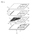
- Fig. 4 is an exploded view of the configuration of a cooling device disclosed in Japanese Patent Application Laid-Open No. 209531/1998. This cooling device is a different type from that diagrammed in Fig. 3 which is for cooling one one-dimensional laser diode array.
- the cooling device 134 is configured by three plate-form members 135, 136, and 137 which are made of a material such as copper which exhibits high thermal conductivity.
- the grooves 33 described above, which are formed on the lower surface of the plate-form member 135 on the upper side and on the upper surface of the plate-form member 137 on the lower side configure cooling water channels 138.
- Ridges 35 that divide the grooves 33 from adjacent grooves 33 on the lower surface of the plate-form member 135 on the upper side are connected thermally and mechanically to the plate-form member 136 in the middle.
- a plurality of very small through holes 139 that are mutually independent is formed, and bridges 140 between those very small through holes 139 and 139 contribute both to thermal conductivity and to the prevention of deformity in this middle plate-form member 136.
- the thermal connection between the three plate-form members 135, 136, and 137 is improved. Accordingly, by efficiently dispersing the heat generated by the laser bar 22 within the wide scope of this cooling device 134, not only is outstanding cooling performance achieved, but the mechanical strength of the cooling device 134 is also improved.
- the process steps for forming the plate-form members can be performed by chemical etching, wherewith many process steps can be done simultaneously, and many cooling devices can also be assembled simultaneously, so low-cost manufacturing is possible.
- cooling devices exhibiting outstanding cooling performance can be realized at low cost.
- more non-emitting areas develop, as seen from the light emitting surface side, just as with the surface emitting device diagrammed in Fig. 2. That being so, when an attempt is made to deploy an even larger plurality of these surface emitting devices to configure a surface emitting light source having a larger light emitting surface area, because the degree of layout freedom is low, there are restrictions such as that it is difficult to realize a surface emitting light source having few non-emitting parts.
- the surface emitting device comprising the cooling device 119 diagrammed in Fig. 1B described earlier, on the other hand, it is possible to make the configuration one wherein almost the entire surface is a light-emitting surface, seen from the light-emitting surface side, as in the surface emitting device 118 diagrammed in Fig. 1A. That being so, when an attempt is made to deploy an even larger plurality of these surface emitting devices 118 to configure a surface emitting light source having a larger light emitting surface area, the degree of layout freedom is high, wherefore there is a benefit in being able to make a surface emitting light source having few non-emitting parts.
- the heat generated by the laser bar 22 is conducted through the bar support plate 120, from there passes through the insulating plate 121 and heat sink plate 122, and is discharged after heat exchange with the cooling liquid 123, wherefore the thermal resistance between the laser bar 22 and the cooling liquid 123 inevitably becomes higher.
- the electrical current that can be input into the laser bar 22 and it becomes very difficult to raise the light output per laser bar 22.
- the thickness of the bar support plate 120 is made thicker in an attempt to lower the thermal resistance, even if only slightly, in order to raise the light output per laser bar 22, the laser bar 22 pitch becomes greater, and, as a consequence, the light output intensity that is the light output per unit light emitting surface area in the surface emitting device is still kept low, so there is still a problem.
- the laser bars 22 are thermally connected to the individual cooling units 125, respectively, wherefore the cooling liquid can be made to flow more or less directly below the positions where the laser bars 22 are deployed. Accordingly, if improvements are made so that the heat exchange between the cooling liquid and the inner walls of the water channels inside the cooling units near the laser bars 22 is done efficiently, it becomes possible to keep down the heat resistance between the laser bar 22 and the cooling liquid, thereby holding temperature rises in the laser bars 22 due to heat generation down to a low level.
- the non-emitting areas as seen from the light emitting surface side become great because of the deployment, on the outside of the stacked plurality of cooling units 125, of a pipeline for inducting the cooling liquid in the intake opening 8 and a pipeline for discharging the cooling liquid from the outlet opening 9, and the deployment of a tightening bolt 20 to prevent leakage of cooling liquid from between the cooling units 125 and 125.
- the size of the light-emitting surface in the direction perpendicular to the direction in which the cooling units are stacked can be made large by deploying a plurality of the surface emitting devices diagrammed in Fig. 2 adjacent to each other in that direction.
- a plurality of the surface emitting devices diagrammed in Fig. 2 cannot be deployed proximately in that direction, whereupon a wide non-light-emitting part develops, and a problem arises in that the solid laser medium can no longer be uniformly excited.
- the upper limit on the number of cooling units that can be stacked is normally about 30.
- cooling units which have the microchannels 133 so that the heat exchange between the cooling liquid and the inner walls of the water channels inside the cooling units near the laser bars can be done efficiently, as in the cooling unit 125 diagrammed in Fig. 3 described earlier, problems arise in that it is very difficult to form the very fine structures of the microchannels 133 by conventional chemical etching, whereupon laser processing is used, wherefore it is necessary to process the thin plates 126 to 130 one plate at a time, and processing costs escalate.
- a minimum of five of the thin plates configuring the cooling unit 125 are necessary.
- the thin plates are made of copper, they are readily deformed by the heat and pressure brought to bear on them during processing, particularly when joining them together by diffusion welding or the like.
- the parts corresponding to the adjacent copper thin plates that cover the cooling liquid flow channels cut out by laser beam are particularly susceptible to being crushed, and similar deformation readily occurs in the cooling unit front end surface 12 of the thin plate 128 wherein the slot 132 is formed.
- deformations in the cooling unit 125 distort the laser bar 22 mounted thereon and, as a result, cause the laser bar characteristics to deteriorate.
- cooling device 134 diagrammed in Fig. 4, moreover, by efficiently diffusing the heat generated by the laser bar 22 within the wide scope of the cooling unit 134, outstanding cooling performance is realized, even without using the microchannels 133, and the mechanical strength of the cooling unit 134 is enhanced.
- the process steps for forming the plate-form members described above can by done by chemical etching wherewith many such processes can be done simultaneously, and many cooling units can also be assembled simultaneously, wherefore low-cost manufacturing is possible.
- a cooling unit can be realized that exhibits outstanding cooling performance at low cost, whereupon almost all of the problems associated with the cooling unit 125 diagrammed in Fig. 3 are resolved. Nevertheless, even in this surface emitting device in which this cooling unit 134 is used, the non-light-emitting area as seen from the light-emitting surface side increases in a similar manner to Fig. 2, and, when an attempt is made to deploy an even larger plurality of these surface emitting devices to configure a surface emitting light source having a larger light emitting surface area, there are restrictions, due to the fact that the degree of layout freedom is low, such as that it will in some cases be difficult to realize a surface emitting light source having few non-emitting parts.
- An object of the present invention is to provide a cooling device that has high cooling capacity and also facilitates a large degree of freedom in the layout of the objects to be cooled .
- a more specific object thereof, in cases where the objects to be cooled are laser diode arrays, is to realize, at low cost, a large-scale surface emitting light source that exhibits high light output intensity per laser diode array as a consequence of there being few non-light-emitting parts as seen from the light-emitting surface side, and of the thermal resistance between the laser diode arrays and the cooling liquid being low.
- a cooling device is a cooling device that is formed by stacking up cooling units to which objects to be cooled are mounted, comprising: a first cooling liquid supply passage deployed so as to pass through first portions of the cooling units in order to conduct the cooling liquid about the periphery of each of the objects to be cooled; a cooling liquid discharge passage deployed so as to pass through second portions of the cooling units in order to discharge the cooling liquid that has cooled each of the objects to be cooled to the outside of the cooling device; and a second cooling liquid supply passage that passes through third portions of the cooling units, and is connected to the first cooling liquid supply passage, wherewith cooling liquid is supplied from the outside.
- a cooling device can be configured as described above, with the degree of freedom in the layout of the objects to be cooled being able to be increased while maintaining the cooling capacity relative to the objects to be cooled.
- each of the cooling units noted above can be made to be such that it comprises a primary cooling unit that has two holes provided therein that open respectively to the first cooling liquid supply passage and the cooling liquid discharge passage, and a secondary cooling unit that has at least three holes provided therein that open, respectively, to the first cooling liquid supply passage, the cooling liquid discharge passage, and the second cooling liquid supply passage.
- the secondary cooling units can be made such that they connect the first cooling liquid supply passage and the second cooling liquid supply passage, and also comprise a plurality of flow channels divided by ridges.
- the secondary cooling units can be made such that they connect the first cooling liquid supply passage and the second cooling liquid supply passage, and also comprise a plurality of flow channels divided by ridges.
- the cooling device described in the foregoing can also be made such as to comprise pressure bonding means for pressure bonding the stacked cooling units.
- cooling liquid can be prevented from leaking from between the cooling units.
- a belt that securely tightens the stacked cooling units can be made the pressure bonding means noted above.
- cooling units are securely tightened together by a belt or belts as described above, not only can the cooling unit structure be simplified, but the widths of the first and second cooling liquid supply passages and cooling liquid discharge passage described earlier can be made wider, so that pressure loss can be reduced.
- the cooling device described in the foregoing can also be made such that, in addition to a plurality of cooling units being deployed so that they are lined up, a cooling liquid induction pipeline is also provided which is connected to all of the second cooling liquid supply passages contained in the cooling units that are deployed so that they are lined up.
- the cooling device described in the foregoing can also be made such that a second cooling liquid discharge passage is provided that discharges the cooling liquid to the outside of the cooling device, being connected to the cooling liquid discharge passage and also passing through fourth portions of the cooling units.
- the cooling units comprise a first cooling unit wherein are provided two holes that open, respectively, to the first cooling liquid supply passage and the cooling liquid discharge passage, a second cooling unit wherein are provided at least three holes that open, respectively, to the first cooling liquid supply passage, the cooling liquid discharge passage, and the second cooling liquid supply passage, and a third cooling unit wherein are provided at least three holes that open, respectively, to the first cooling liquid supply passage, the second cooling liquid supply passage, and the second cooling liquid discharge passage that is connected to the cooling liquid discharge passage described earlier.
- the cooling device described in the foregoing can also be made such that, in addition to a plurality of cooling units being deployed so that they are lined up, a cooling liquid discharge pipeline is also provided which is connected to all of the second cooling liquid discharge passages contained in the cooling units that are deployed so that they are lined up.
- the surface emitting device is a surface emitting device wherein laser diode arrays mounted to cooling units are stacked up, comprising: a first cooling liquid supply passage deployed so as to pass through first portions of the cooling units in order to conduct the cooling liquid about the periphery of each of the laser diode arrays; a cooling liquid discharge passage deployed so as to pass through second portions of the cooling units in order to discharge the cooling liquid that has cooled each of the laser diode arrays to the outside of the surface emitting device; and a second cooling liquid supply passage that passes through third portions of the cooling units, and is connected to the first cooling liquid supply passage, wherewith cooling liquid is supplied from the outside.
- the surface emitting device according to the present invention is configured as described in the foregoing, wherefore a surface emitting device can be obtained wherein laser diode arrays are deployed in higher density.
- the surface emitting device described above can be made to comprise a belt or belts for securely tightening the stacked cooling units.
- the surface emitting device described above can be made to comprise also a lens or lenses held by the belt or belts noted above, deployed facing the surface formed by the stacked laser diode arrays.
- cooling devices can be realized which have high cooling capacity and allow a great degree of freedom in deploying the objects to be cooled.
- those objects to be cooled are laser diode arrays, a surface emitting device can be obtained which has high light output intensity and little non-light-emitting area as viewed from the light-emitting surface formed by the laser diode arrays.
- cooling liquid can be supplied from the back side so that cooling liquid can be supplied as far as immediately below all of the laser diode arrays. Accordingly, a surface emitting device can be obtained which exhibits uniform light emission intensity, wherewith the occurrence of light emission intensity irregularity induced by laser diode array temperature differences caused by differences in cooling capacity can be suppressed.
- the mechanical strength of the cooling unit will decline, so that deformations will arise, such as the cavity portion inside the flow channels being crushed during the process of joining the cooling units together wherein pressure is applied and the temperature is raised, for example. That will lead to the flow channels becoming blocked or to cooling liquid leakage, and the assembly yield will decline. That being so, the multiple flow channels are divided by the ridges to prevent cooling unit deformation, and it thereby becomes possible to fabricate highly reliable cooling units having good mechanical strength with good production yield.
- cooling units of electrically conductive materials having a coefficient of thermal conductivity of 1.5 W/cm/K or greater, it becomes possible to efficiently discharge the heat generated by the objects to be cooled into the cooling liquid, and outstanding cooling performance can be realized. All of the cooling units stacked up can be fabricated from the same material, moreover, making it possible to unify the fabrication processes and to reduce fabrication costs.
- the cooling liquid can be inducted as far as immediately below the objects to be cooled, and a cooling device that exhibits very high cooling performance can be obtained, even without using a tightening bolt to prevent cooling liquid leakage. That being so, by providing such a cooling device as this, in cases where the objects to be cooled are laser diode arrays, surface emitting devices can be obtained which exhibit high light output intensity, having little non-light-emitting area as seen from the light-emitting surface side.
- the belt or belts noted above can also be used as an outer protective container for protecting the laser diode arrays. While reducing the danger of inadvertently damaging the laser diode arrays during maintenance, etc., a surface emitting device can be realized which, inclusive of the outer protective container, has few non-light-emitting parts as seen from the light-emitting surface. And, as compared to loading the surface emitting device inside a separately prepared outer protective container, surface emitting devices equipped with outer protective containers can be obtained at lower cost.
- the belt described in the foregoing serves also as an outer protective container to hold a lens or lenses for collimating the laser beams from the laser diode arrays and converting them to parallel light, etc.
- the lens or lenses can be deployed with good precision, without making the overall device size large, and low-cost surface emitting devices can be obtained.
- a cooling device is obtained wherewith the cooling liquid can be inducted from the outside without increasing the number of pipelines.
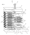
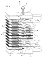
- Fig. 5 is an exploded view representing the configuration of a surface emitting device that comprises a cooling device relating to this embodiment.
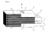
- Fig. 6 is a diagonal view of that surface emitting device after it has been assembled.
- Fig. 7 is a partial diagram of the same surface emitting device.
- the cooling device is configured by stacking together two types of cooling unit having differing sizes (lengths), that is, a large cooling unit 1 and a small cooling unit 2.
- Each of the cooling units comprises a stack structure made by stacking together a plurality of plate-form members. Cooling liquid flows inside the stack structure, and thereby cools a laser bars that is mounted on the stack structure along the front end surface of the stack structure.
- the large cooling units 1 and the small cooling units 2 are stacked together with the front end surfaces to which the laser bars 22 are mounted aligned, due to the differences in length between the two types, there is an additional area 3 in the large cooling units that protrude in the direction opposite the front end surface.
- this additional area 3 are provided an inflow opening 4 and an outflow opening 5 for the cooling liquid.
- a plurality of the large cooling units 1 is stacked up continuously, wherefore the inflow openings 4 and outflow openings 5 formed in the additional areas 3 of the large cooling units connect vertically with each other to form an inflow passage 6 and an outflow passage 7 (cf. Fig. 7).
- both the large cooling units 1 and the small cooling units 2 at positions that mutually correspond when they are stacked together with the respective front end surfaces thereof aligned, are provided intake openings 8 and outlet openings 9. Accordingly, when a plurality of cooling units 1 and 2 are stacked together continuously with their respective front end surfaces aligned, the intake openings 8 and outlet openings 9 of the stacked cooling units 1 and 2 connect vertically with each other to form an intake passage 10 and the outlet opening 9 (cf. Fig. 7).
- a cooling liquid induction port 15 and a cooling liquid discharge port 17 are formed in the first tightening part 18 in the extra space 13.
- the cooling liquid discharge port 17 is connected to a discharge pipeline 16 that is for returning the cooling liquid back to the cooling liquid supply unit.
- the elastic spacer members 21 are diagrammed as only deployed at the positions of some of the intake openings 8 and outlet openings 9 and some of the inflow openings 4 and outflow openings 5, but this is to make the diagram easier to understand, and in actual practice they are deployed at the positions of all of the intake openings 8 and outlet openings 9 and all of the inflow openings 4 and outflow openings 5.
- the numbers of the large cooling units 1 and small cooling units 2 are diagrammed as being fewer than in actual practice to keep the diagram from becoming too complex.
- the inflow openings 4 and intake openings 8 are connected by inflow water passages 32 (cf. Fig. 8C and Fig. 9B) provided inside the large cooling units 1, while the outflow openings 5 and the outlet openings 9 are connected by outflow water passages 34 (cf. Fig. 8C and Fig. 9B) provided in the large cooling units 1.
- cooling liquid intakes connecting to the cooling water passages provided inside the cooling units are provided on the sides of the intake openings 8, while cooling liquid outlets connecting to those cooling water passages provided inside the cooling units are provided on the sides of the outlet openings 9, and the cooling water passages extend to positions roughly immediately below the laser bars 22 mounted along the front end surfaces of the cooling units.
- the cooling liquid supplied from the cooling liquid supply unit through the induction pipeline 14 passes through the cooling liquid induction port 15 and flows into the inflow passage 6 that is the aggregate of the inflow openings 4, further passes through the inflow water passages 33 provided inside the large cooling units 1, and flows into the intake passage 10 that is the aggregate of the intake openings 8.
- cooling liquid enters into the cooling water passages inside the cooling units from the cooling liquid intakes in all of the cooling units, captures the heat generated by the laser bars 22, then leaves by the cooling liquid outlets and is again collected at the outlet passage 11 that is the aggregate of the outlet openings 9.
- the cooling liquid collected in the outlet passage 11 passes through the outflow water passages provided inside the large cooling units 1, flows into the outflow passage 7 that is the aggregate of the outflow openings 5, passes through the cooling liquid discharge port 17, is discharged into the discharge pipeline 16, and is returned to the cooling liquid supply unit.
- connecting metal plates 39 and 44 are deployed so as to sandwich patterned insulating tapes 40 and 45 having a bonding agent applied to both sides thereof (cf. Fig. 12B and Fig. 13B). Electrodes of the laser bars 22 on the side opposite from those joined to the cooling units are electrically connected by bonding wire wiring or the like to the connecting metal plates 39 and 44 (cf. Fig. 12E and Fig. 13E).
- insulative thin plates 23 are sandwiched between the tightening parts 18 and 19, and a positive electrode terminal plate 24 and negative electrode terminal plate 25 are provided. By passing an electric current between these electrode terminal plates 24 and 25, it becomes possible to input current to all of the laser bars in a condition wherein many of the laser bars 22 are connected in series, and the surface emitting device 26 is formed.
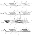
- Fig. 8A to 8D provide an exploded view of the configuration of the large cooling liquid 1, while Fig. 8D is a diagonal diagram of that large cooling unit in its assembled state.
- the large cooling unit 1 is formed by stacking up three plate-form members 27, 28, and 29 that are made of a metal having a high coefficient of thermal conductivity, such as copper or a copper alloy or the like, which typically has a coefficient of thermal conductivity of 1.5 W/cm/K or greater.
- a metal having a high coefficient of thermal conductivity such as copper or a copper alloy or the like, which typically has a coefficient of thermal conductivity of 1.5 W/cm/K or greater.
- inflow opening 4 namely in the first plate-form member 27 (Fig. 8A), the second plate-form member 28 (Fig. 8B), and the third plate-form member 29 (Fig. 8C)
- an inflow opening 4 an outflow opening 5
- an intake opening 8 an outlet opening 9
- a tightening bolt hole 30 a guide pin hole 31.
- the first, second, and third plate-form member 27, 28, and 29, respectively, typically have a thickness of 250 ⁇ m.
- These inflow water passages 32 and outflow water passages 34 typically have a depth of 139 ⁇ m, a width of 400 to 700 ⁇ m, and a pitch of 550 to 850 ⁇ m.
- the grooves 33 formed in the first and second plate-form members 28 and 29 are demarcated between ridges 35 and ridges 35, and, at places in the inflow water passages 32 and the outflow water passages 34 where it is necessary to alter the overall widths of the individual water passages due to the presence of the tightening bolt hole 30 or the like, the grooves 33 branch so that the groove width does not greatly change.
- the small cooling unit 2 also, as diagrammed in Fig. 10A to 10C, is formed by stacking three plate-form members 36, 37, and 38.
- the structure of these plate-form members 36, 37, and 38 is the same as that of the three plate-form members 27, 28, and 29 configuring the large cooling unit from the front end surface to the center, including the intake openings 8 and the outlet openings 9.
- the second plate-form member 28 diagrammed in Fig. 8B is placed, and on the second plate-form member 28 is placed the first plate-form member 27 diagrammed in Fig. 8A, whereupon the large cooling unit 1 diagrammed in Fig. 8D is formed.
- the inflow openings 4 and the intake openings 8 are connected by the inflow water passages 32, and the outflow openings 5 and the outlet openings 9 are connected by the outflow water passages 34.
- the first plate-form member 27 may be given the same structure as the third plate-form member 29 (that is, made so that the same pattern of grooves 32 is formed thereon as that formed on the upper surface of the third plate-form member 29). In that case, by turning one of the third plate-form members 29 over and deploying it on the second plate-form member 28, and deploying the other third plate-form member 29 below the second plate-form member 28, the large cooling unit 1 is formed. Hence the large cooling unit 1 can be configured with only two types of plate-form member.
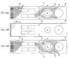
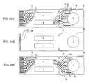
- Fig. 9A is a plan of the second plate-form member 28 diagrammed in Fig. 8
- Fig. 9B is a plan of the first plate-form member 27 (and of the third plate-form member 29 having the same structure) diagrammed in Fig. 8.
- Fig. 10A to 10D provide an exploded view of the configuration of the small cooling unit 2, while Fig. 10D is a diagonal diagram of that small cooling unit 2 in its assembled state.
- the small cooling unit 2 is formed by stacking up three plate-form members 36, 37, and 38 that are made of a metal having a high coefficient of thermal conductivity, such as copper or a copper alloy or the like, which typically has a coefficient of thermal conductivity of 1.5 W/cm/K or greater.
- a metal having a high coefficient of thermal conductivity such as copper or a copper alloy or the like, which typically has a coefficient of thermal conductivity of 1.5 W/cm/K or greater.
- intake openings 8, outlet openings 9, and guide pin holes 31 are formed in each of these first, second, and third plate-form members 36, 37, and 38 that are formed intake openings 8, outlet openings 9, and guide pin holes 31.
- the guide pin holes 31 are formed in the plate-form members in order to stack cooling units of different length so that they line up. And the aspect ratio of the plate-form members is changed from the conventional example diagrammed in Fig. 4 in order to reduce the lateral width of the cooling unit so that it approaches the length of the laser bars which typically have a length of 1 cm, in order to diminish the non-light-emitting parts, as seen from the light-emitting surface, and in order to extend the length of the cooling unit, in conjunction therewith, so that the surface areas of the intake openings and outlet openings are not reduced.
- the small cooling unit 2 can also, as the large cooling unit 1, be configured with only two types of plate-form member.
- Fig. 11A is a plan of the second plate-form member 38 diagrammed in Fig. 10B
- Fig. 11B is a plan of the first plate-form member 36 (and of the third plate-form member 38 having the same structure) diagrammed in Fig. 10A.
- Fig. 12A to 12D provide an exploded view that represents the configuration of a light emitting element component 41 (laser bar module) formed by mounting the laser bars 22, connecting metal plate 39, and patterned tape 40, etc., to the large cooling unit 1 diagrammed in Fig. 8D.
- Fig. 12E is a diagonal view of that light emitting element component 41 in its assembled state (with the elastic spacer members 21 omitted, however).
- the connecting metal plate 39 is bonded onto the cooling unit 1 by the patterned insulating tape 40 which has a bonding agent applied to both sides thereof.
- Those electrodes of the laser bars 22 joined to the cooling unit 1 and those on the opposite side are electrically connected to the connecting metal plate 39 by bonding wire wiring or the like.
- the lower surface of the large cooling unit 1 and the upper surface of the connecting metal plate 39 function as current terminals for passing electric currents to the laser bars 22.
- a plurality of these light emitting element components 41 is stacked together, it becomes possible to supply current to all of the laser bars in a condition wherein many laser bars 22 are connected in series, and the surface emitting device 26 diagrammed in Fig. 6 is formed.
- outflow/inflow openings 110 and outlet/inlet openings 42 are formed in addition to the tightening bolt holes 30 and guide pin holes 31.
- the outflow/inflow openings 110 are formed in areas corresponding to the inflow openings 4 and the outflow openings 5 and the vicinities thereof, while the outlet/inlet openings 42 are formed in areas corresponding to the intake openings 8 and the outlet openings 9 and the vicinities thereof.
- water passing openings 43 are formed respectively in parts corresponding to the inflow openings 4, outflow openings 5, intake openings 8, and outlet openings 9 of the cooling unit 1.
- the thickness of the elastic spacer members 21 is slightly thicker than the sum of the thicknesses of the connecting metal plate 39 and the patterned insulating tape 40.
- Fig. 13A to 13D provide an exploded view that represents the configuration of a light emitting element component 46 (laser bar module) having the laser bars 22, connecting metal plate 44, and patterned tape 45, etc., mounted to the small cooling unit 2 diagrammed in Fig. 10D.
- Fig. 13E is a diagonal view of that light emitting element component 46 in its assembled state (with the elastic spacer members 21 omitted, however).
- the functions of the connecting metal plate 44 and the patterned insulating tape 45 are the same as the functions of the connecting metal plate 39 and the patterned insulating tape 40 used in the large cooling unit 1 diagrammed in Fig. 12B and Fig. 12C.
- the connecting metal plate 44 and the patterned insulating tape 45 have outlet/inlet openings 42 formed therein in addition to the guide pin holes 31. These outlet/inlet openings 42 are formed in areas corresponding to the intake openings 8 and outlet openings 9, and the vicinities thereof, in the small cooling unit 2.
- water passing openings 43 are formed respectively in parts corresponding to the intake openings 8 and outlet openings 9 of the cooling unit 2.
- the thickness of the elastic spacer members 21 is slightly thicker than the sum of the thicknesses of the connecting metal plate 44 and the patterned insulating tape 45.
- the thicknesses of the connecting metal plate 39 mounted to the large cooling unit 1 and of the connecting metal plate 44 mounted to the small cooling unit 2 are made the same, and the thicknesses of the patterned insulating tape 40 mounted to the large cooling unit 1 and of the patterned insulating tape 45 mounted to the small cooling unit 2 are made the same.
- Fig. 14 is an exploded view that represents the configuration of a surface emitting device that comprises a cooling device related to this embodiment.
- the surface emitting device diagrammed in Fig. 14 employs two types of large cooling unit having structures that differ from that of the large cooling unit 1 of the first embodiment (namely, a first type large cooling unit 47 and a second type large cooling unit 48), and a small cooling unit 2 having the same structure as the small cooling unit 2 of the first embodiment.
- the large cooling units 47 and 48 and the small cooling units 2 are stacked together so that the front end surfaces on the side where the laser bars 22 are mounted line up, as in the first embodiment. Thereupon, because the large cooling units 47 and 48 are longer than the small cooling units 2, the back ends thereof will protrude and form additional areas 3.
- additional areas 3 of the first type large cooling unit 47 are formed inflow openings 4 for the cooling liquid.
- the inflow openings 4 thereof are connected vertically to form an inflow passage 6.
- the outflow openings 5 for the cooling liquid In the additional spaces 3 of the second type large cooling units 48, on the other hand, are formed outflow openings 5 for the cooling liquid.
- the outflow openings 5 thereof are connected vertically to form an outflow passage 7.
- a cooling liquid induction port 15 that is connected to an induction pipeline 14 for inducting cooling liquid from a cooling liquid supply unit (not shown).
- a cooling liquid supply unit not shown.
- a cooling liquid discharge port 17 that is connected to the discharge pipeline 16 for returning the cooling liquid back to the cooling liquid supply unit noted above. That liquid discharge port 17 cannot be seen in Fig. 14 because the lower surface of the second tightening part 19 is not open to view.
- the cooling liquid discharge port 17 thereof corresponds to the outflow openings 5 of the second type large cooling units 48.
- Fig. 14 furthermore, as in the case diagrammed in Fig. 5, elastic spacer members 21 are shown deployed only in the positions of some of the intake openings 8 and outlet openings 9 and some of the inflow openings 4 and outflow openings 5. This is to make the diagram easier to understand, however. In actual practice, elastic spacer members 21 are deployed, respectively, in the positions of all of the intake openings 8 and outlet openings 9 and all of the inflow openings 4 and outflow openings 5. In Fig. 14, moreover, the large cooling units 47 and 48 and the small cooling units 2 are shown in fewer numbers than actual in order to keep the diagram from becoming too complex.
- the first type large cooling units 47 are deployed on the side of the first tightening part 18 where the cooling liquid induction port 15 is provided, and the inflow openings 4 and intake openings 8 are connected by inflow water passages 32 (cf. Fig. 15A) provided inside the large cooling units 47.
- the second type large cooling units 48 are deployed on the side of the second tightening part 19 where the cooling liquid discharge port 17 is provided, and the outflow openings 5 and outlet openings 9 are connected by outflow water passages 34 (cf. Fig. 15A) provided inside the large cooling units.
- the cooling liquid that is supplied from the cooling liquid supply unit via the induction pipeline 14 passes through the cooling liquid induction 15 and flows into the inflow passage 6 that is the aggregate of the inflow openings 4, and from there passes through inflow water passages 32 provided inside the first type large cooling units 47 and flows into the intake passage 10 that is the aggregate of the intake openings 8.
- the cooling liquid after entering from the cooling liquid intakes of all of the cooling units into the cooling water channels inside the cooling units and capturing the heat generated by the laser bars 22, is then discharged from the cooling liquid outlets and is again collected in the outlet passage 11 that is the aggregate of the outlet openings 9.
- the cooling liquid collected in the outlet passage 11 passes through the outflow water passages 34 provided inside the second type large cooling units 48, flows into the outflow passage 7 that is the aggregate of the outflow openings 5, passes through the cooling liquid discharge port 17, is discharged into the discharge pipeline 16, and is returned back to the cooling liquid supply unit.
- the plate-form members 49, 50, and 51 used in the first type large cooling unit 47 are represented by the plans given in Fig. 15A, 15B, and 15C.
- the first plate-form member 49 and the third plate-form member 51 respectively, have shapes in the back portions thereof that exhibit a relationship of linear symmetry. These first and second plate-form members 49 and 51 are deployed, and mutually joined, so that the surfaces thereof wherein are formed the grooves 33 are in contact with the upper and lower surfaces, respectively, of the second plate-form member 50, whereupon the first type large cooling unit 47 is formed. This first type large cooling unit 47 is used so that the first plate-form member 49 is deployed on the upper side thereof.
- the second type large cooling unit 48 corresponds to the first type large cooling unit 47, described above, when it has been turned over. That is, the first type large cooling unit 47 can be turned over and used as the second type large cooling unit 48.
- the first type large cooling units 47 and the second type large cooling units 48 are built into a surface emitting device 52 of Fig. 14, in the form of light-emitting element components wherein are mounted laser bars, connecting metal plates, and patterned insulating tapes, etc.
- the number of cooling units that can be fabricated at one time is roughly inversely proportional to the surface area of the cooling units (cf. Fig. 38A to 38C), wherefore it is important in the interest of cost reduction to make the overall length of the large cooling units as short as possible.
- Fig. 16A to 16C are plans of plate-form members 54, 55, and 56 used in a large cooling unit 53 for configuring a cooling device relating to this embodiment.
- the second plate-form member 55 and the third plate-form member 56 have the same structures, respectively, as the second plate-form member 50 (cf. Fig. 15B) and the third plate-form member 51 in the second embodiment.
- large cooling unit 53 fabricated by mutually joining these first and third plate-form members 54 and 56 together so that the surfaces thereof whereon the grooves 33 have been formed contact the upper and lower surfaces, respectively, of the second plate-form member 55 (which large cooling unit 53 is hereinafter called a third type large cooling unit), there is no inflow opening 4 or outflow opening 5 that passes all the way through.
- Fig. 17 which partially represents the configuration of the cooling device relating to this embodiment, is a cross-section in the vicinity of the inflow openings and outflow openings of the stacked large cooling units.
- two of the third type large cooling units 53 are stacked and deployed between the first type large cooling unit 47 and the second type large cooling unit 48.
- the first plate-form member 54 configuring the same faces upward, while, in the other of those third type large cooling units 53, the first plate-form member 54 configuring the same faces downward.
- the first type large cooling unit 47 and the second type large cooling unit 48 are made identical components that are in a relationship of being turned backwards to each other. In that case, partitioning walls are required to separate the inflow passage 6 from the outflow passage 7.
- Elastic spacer members 57 having no water passing openings, as in the second embodiment, may be used, but one must worry about such things as deformation in the elastic spacer members 57 due to the difference in cooling liquid pressure on the inflow side and the outflow side. That being so, in this embodiment, it is preferable that a third type large cooling unit 53 be used wherein there is no inflow opening 4 or outflow opening 5 that passes all the way through.
- the first, second, and third type large cooling units 47, 48, and 53 are represented in a condition wherein a connecting metal plate 58 and a patterned insulating tape 59 is mounted to each.
- the reliability of the surface emitting device 52 in the second embodiment is raised even higher while holding down to a minimum any increase in the number of components which would cause costs to increase.
- Fig. 18A, 18B, and 18C are plans of plate-form members 61, 62, and 63, respectively, which configure a small cooling unit 60 that is used in a cooling device based on this embodiment.
- the first plate-form member 61 In the first plate-form member 61, no inlet opening or outlet opening is opened, as diagrammed in Fig. 18A.
- the second plate-form member 62 As diagrammed in Fig. 18B, has the same structure as the plate-form member 37 (cf. Fig. 10B) used in the first embodiment.
- the third plate-form member 63 as diagrammed in Fig. 18C, has the same structure as the plate-form member 38 (cf. Fig. 10C) used in the first embodiment.
- the small cooling unit 60 fabricated by mutually joining these first and third plate-form members 61 and 63 together so that the surfaces thereof whereon the grooves 33 have been formed contact the upper and lower surfaces, respectively, of the second plate-form member 62 (which small cooling unit 60 is hereinafter called a second type of small cooling unit), there is no intake opening 8 or outlet opening 9, respectively, that passes all the way through.
- This second type of small cooling unit 60 which has no intake opening 8 or outlet opening 9, respectively, that passes all the way through it, can be used in the surface emitting device 26 (first embodiment) diagrammed in Fig. 5 or in the surface emitting device 52 (second embodiment) diagrammed in Fig. 14 instead of the outermost small cooling unit 2 in the stacked cooling units.
- one second type small cooling unit 60 is deployed, in the lowermost layer of the stacked cooling units, so that the first plate-form member 61 configuring the same is made to be on the lower side, and another second type small cooling unit 60 is deployed, in the uppermost layer of the stacked cooling units, so that the first plate-form member 61 configuring the same is made to be on the upper side. Based on this configuration, leakage of cooling liquid from the intake openings 8 and outlet openings 9 in the stacked cooling units can be prevented more completely, without being influenced by the flatness of components outside of the cooling units such as the negative electrode terminal plate 25.
- cooling device related to this embodiment moreover, increases in the number of components, which constitutes a cause of escalating costs, can be held down to a minimum, and the reliability of the surface emitting device 52 in the second embodiment can be raised even higher.
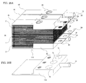
- Fig. 19A is a diagonal view of a large cooling unit 1
- Fig. 19B is a diagonal view of a small cooling unit 12. From this large cooling unit 1 diagrammed in Fig. 19A and small cooling unit 12 diagrammed in Fig. 19B is formed the cooling device diagrammed in Fig. 19C.
- the large cooling unit 1 diagrammed in Fig. 19A is configured by five plate-form members 141 to 145, as diagrammed in Fig. 20A to 20E.
- a cooling liquid intake opening 8 and outlet opening 9 and an inflow opening 4 and outflow opening 5 are formed.
- an outflow water passage 34 that connects the outlet opening 9 and the outflow opening 5, a cooling liquid flow channel 131, the width whereof widens as it extends from the intake opening 8 to the front end surface of the cooling unit, which connects the inflow opening 4 and the intake opening 8, and microchannels 133 which are formed along the front end surface of the cooling unit.
- the third plate-form member 143 are formed an intake opening 8 and an outlet opening 9, an inflow opening 4 and an outflow opening 5, and a slit 132 that configures a cooling liquid flow channel corresponding to the front end surface of the cooling unit in the cooling liquid flow channel 131 described above, and which is independent of the intake opening 8 and the outlet opening 9 described above.
- the fourth plate-form member 144 are formed an inflow water passage 32 that connects the intake opening 8 and the inflow opening 4 of the third plate-form member 143, and a cooling liquid flow channel 131, the width whereof narrows as it extends from a site corresponding to the slit 132 in the third plate-form member 143 toward a site corresponding to the outlet opening 9 in the third plate-form member 143, which connects the outlet opening 9 and the outflow opening 5 of the third plate-form member 143.
- the fifth plate-form member 145 has the same layout as the first plate-form member 141.
- first to fifth plate-form members 141 to 145 are deployed such that the first plate-form member 141 is deployed at the very top, followed in order therebelow by the second, third, and fourth plate-form member, and then the fifth plate-form member 145 is deployed at the very bottom.
- the first to fifth plate-form members 141 to 145 are each made of a material such as copper that exhibits a high coefficient of thermal conductivity.
- the cooling liquid inducted into the inflow openings 4 thereof passes through the microchannels 133 and from there is discharged to the outflow openings 5.
- the laser bar (not shown) deployed along the front end surface on the plate-form member 145 is cooled by that cooling liquid.
- the microchannels 133 are formed very fine flow channels having widths on the order of 20 ⁇ m, by a laser process or the like, for the purpose of checking the decline in heat exchange efficiency induced by a boundary layer of the cooling liquid.
- the small cooling unit 12 has the same structure as the cooling unit 125 (conventional example) diagrammed in Fig. 3.
- cooling device relating to this embodiment provides the same benefits as the cooling devices relating to the embodiments described earlier.
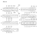
- FIG. 22, in (A) to (G), represents various modification examples of a cooling device relating to this embodiment.
- These diagrams, respectively, are vertical cross-sections for inflow water passages or outflow water passages of large cooling units that are configuring components in a cooling device.
- this be the one wherein the cross-sectional area of the water passages is greater in order to reduce pressure loss in the cooling liquid in the inflow water passages 32 or outflow water passages 34.
- the same level of water passage cross-sectional area as in (A) can be obtained by configuring as at (D) or (E).
- the grooves 33 can be provided in all three of the plate-form members, increasing the water passage cross-sectional area, as at (F) or (G).
- the grooves 33 are formed by etching from both sides of the plate-form members sandwiched in the middle, as in (E) or (G) in Fig. 22, so that the grooves 33 penetrate through the plate-form members, if the grooves 33 are made to penetrate along their entire lengths, it will become impossible to hold the ridges 35 that form the grooves 33, wherefore, the grooves 33 may be formed from both sides only in those portions where the widths of the inflow water passages 32 or outflow water passages 34 have to be made narrow, for example.
- cooling liquid pressure loss in the inflow water passages 32 or outflow water passages 34 inside the large cooling units is reduced, and the flow volume of the cooling liquid supply to the cooling units can easily be increased and the cooling capacity of the cooling devices thus enhanced.
- the supply pressure required for the cooling liquid supply unit can be reduced, and the demands for the pipeline from the cooling liquid supply unit to be able to withstand pressures can be moderated, thus contributing to lower costs in the cooling units overall.
- FIG. 23A and 23B A seventh embodiment of the present invention is now described with reference to Fig. 23A and 23B.
- Fig. 23A and 23B represent a surface emitting device relating to this embodiment. More specifically, these are diagonal views that diagram the structures of the electrode terminal plates that are configuring components of the surface emitting device and of associated components necessary in the invention relating to this embodiment.
- Fig. 23A are diagrammed the structures of negative electrode terminal plates 64 and 65 that are used in place of the negative electrode terminal plate 25 in the surface emitting device 26 diagrammed in Fig. 6.
- Fig. 23B is diagrammed the structure of a positive electrode terminal plate 66 that is used in place of the positive electrode terminal plate 24 of the surface emitting device 26 diagrammed in Fig. 6.
- an electrode lead-out through hole 67 is formed in the second tightening part 19, at a site corresponding to an area that is separated some distance from the intake opening 8 and outlet opening 9 of the small cooling unit 2.
- the structure is such that the electrode terminal is lead out using the side surface of the first tightening part 18, and an insulating thin plate 23 such as insulating adhesive tape or the like is deployed between the positive electrode terminal plate 66 and the first tightening part 18.
- an insulating thin plate 23 such as insulating adhesive tape or the like is deployed between the positive electrode terminal plate 66 and the first tightening part 18.
- an example is given wherein the electrode terminal plate structure diagrammed in Fig. 23A is applied to the negative electrode terminal plate, and the electrode terminal plate structure diagrammed in Fig. 23B is applied to the positive electrode terminal plate, but this may be reversed so that the electrode terminal plate structure diagrammed in Fig. 23A is applied to the positive electrode terminal plate and the electrode terminal plate structure diagrammed in Fig. 23B is applied to the negative electrode terminal plate.
- cutouts are formed in order to connect the cooling liquid induction port 15 and the cooling liquid discharge port 17 formed in the first tightening part 18 to the inflow passage 6 and outflow passage 7 so that cooling liquid can flow. For that reason, there will be places in this positive electrode terminal plate 24 where the width becomes very narrow. And, because it is necessary to pass large currents of several tens of amperes to the laser bars, not only is the heat generated at the places in this positive electrode terminal plate 24 where the width becomes very narrow a problem, but the decline in efficiency resulting from wasted power consumption is also a problem. Such problems do not arise, however, with the positive electrode terminal plate 66 diagrammed in Fig. 23B.
- the surface emitting device relating to this embodiment it becomes possible to effect lower resistance in the electrode terminal plates by increasing the surface area thereof, and to prevent both declines in reliability resulting from heat generation and declines in light emission efficiency resulting from wasted power consumption.
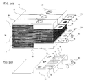
- Fig. 24A is a diagonal view of an overall surface emitting device 69
- Fig. 24B is a diagonal view of a common tightening part 70 that is a component of the surface emitting device 69.
- plural queues (three in Fig. 24A) of combinations of the large cooling units 1 and the small cooling units 2 are arranged in parallel on the common tightening part 70. Accordingly, by implementing this embodiment, a surface emitting device 69 will be realized that is larger in scale than the surface emitting device 26 diagrammed in Fig. 5 wherein a single queue of combinations of the large cooling units 1 and the small cooling units 2 is deployed on the tightening part.
- the common tightening part 70 In the common tightening part 70 noted above, multiple pairs of cooling liquid induction ports 15 and cooling liquid discharge ports 17 are provided, as diagrammed in Fig. 24B, in correspondence with the respective inflow passage 6 and outflow passage 7 in each of the queues of combinations of cooling units arranged in parallel.
- the induction pipeline 14 from the cooling liquid supply unit branches inside the common tightening part 70 and connects to each of the cooling liquid induction ports 15, and the discharge pipeline 16 also branches inside the common tightening part 70 and connects to each of the cooling liquid discharge ports 17.
- each of the second tightening parts 19 may basically have the same structure as the second tightening part 19 diagrammed in Fig. 5.
- the number of pipelines from the cooling liquid supply unit can be reduced, making it easy to install the surface emitting device and to connect the pipelines.
- Fig. 25A is a diagonal view of an overall surface emitting device 111
- Fig. 25B is a diagonal view of a common tightening part 114 that is a component of the surface emitting device 111.
- plural queues three in Fig. 24A
- Fig. 24A plural queues of combinations of the large cooling units 1 and the small cooling units 2 are arranged in parallel on the common tightening part 114.
- cooling liquid induction ports 15 are provided, in correspondence with the inflow passage 6 in each of the queues of combinations of cooling units arranged in parallel.
- the induction pipeline 14 from the cooling liquid supply unit (not shown) branches inside the common tightening part 70 and connects to each of the cooling liquid induction ports 15.
- bolt holes are formed to admit tightening bolts 20 for tightening the queues of stacked cooling units, as in the first tightening part 18 diagrammed in Fig. 14.
- Each of the second tightening parts 19, on the other hand, may basically have the same structure as the second tightening part 19 diagrammed in Fig. 14, and the discharge pipeline 16 to the cooling liquid supply unit (not shown) connects to the cooling liquid discharge port 17.
- the surface emitting device 112 diagrammed in Fig. 26A has plural queues (three in Fig. 26A) of combinations of the large cooling units 1 and the small cooling units 2 arranged in parallel on the common tightening part 114.
- the common tightening part 114 diagrammed in Fig. 26A has the same structure as the common tightening part 114 diagrammed in Fig. 25B.
- the plural queues of cooling units 1 and 2 arranged in parallel have pressure applied thereto, in the direction of stacking, by a second common tightening part 115, so as to prevent cooling liquid leakage.
- multiple cooling liquid discharge ports 17 are provided, in correspondence with the respective outflow passage 7 in each queue of the multiple queues of cooling units arranged in parallel, and the discharge pipeline 16 connected to the cooling liquid supply unit (not shown) branches inside the second common tightening part 115 and connects to each of the cooling liquid discharge ports 17.
- the number of pipelines from the cooling liquid supply unit can be the most reduced, without causing the water passages for connecting the induction pipelines and the cooling liquid induction ports and the water passages for connecting the discharge pipelines and the cooling liquid discharge ports to cross three-dimensionally inside the common tightening part.
- the surface emitting device 113 diagrammed in Fig. 26B has plural queues (three in Fig. 26A) of combinations of the large cooling units 1 and the small cooling units 2 arranged in parallel on the common tightening part 114.
- the common tightening part 114 diagrammed in Fig. 26B has the same structure as the common tightening part 114 diagrammed in Fig. 25B.
- the plural queues of cooling units 1 and 2 arranged in parallel have pressure applied thereto, in the direction of stacking, by a divided connecting type tightening part 116, so as to prevent cooling liquid leakage.
- the divided connecting type tightening part 116 has a structure wherein a plural number of the second tightening parts 19 diagrammed in Fig. 14 are linked. Of the cooling liquid discharge ports, some are directly connected to the discharge pipeline 16 going to the cooling liquid supply unit (not shown), but the others are connected to the discharge pipeline via lines such as bellows 117 which can be deformed within a certain range without being destroyed.
- the number of pipelines from the cooling liquid supply unit can be the most reduced, without causing the water passages for connecting the induction pipelines and the cooling liquid induction ports and the water passages for connecting the discharge pipelines and the cooling liquid discharge ports to cross three-dimensionally inside the common tightening part, and, in addition, cooling liquid leakage that might well occur when the stacked cooling unit thickness totals do not exactly match can be prevented.
- Fig. 27 is a diagonal view of a surface emitting device 71 relating to this embodiment.
- laser beams 72 which in actuality are output from all of the laser bars across the entire laser bar width, are represented as being output from portions of every other laser bar to make the diagram easier to understand.
- a tightening belt 73 made of steel or the like is used to do that tightening, as shown in Fig. 27, whereby leakage of cooling liquid from between the cooling units is prevented and also the laser bars are electrically connected in series.
- the thin portions of the tightening parts 18 and 19 must have some degree of thickness so that they will not be warped by the tightening of the tightening bolt 20.
- the surface emitting device 71 relating to this embodiment by using the tightening belt 73, it becomes possible to tighten the cooling units 2 and 78 across a wide width, wherefore the problem of warping is eliminated, and the overall surface emitting device 71 can be made even thinner.
- the plate-form members 81, 82, and 83 that configure the large cooling units 78 used in the cooling device that configures the surface emitting device 71 diagrammed in Fig. 27 is now described using Fig. 28A to 28C.
- the large cooling unit 78 is fabricated by mutually joining first and third plate-form members 81 and 83 together so that the surfaces thereof whereon the grooves 33 have been formed contact the upper and lower surfaces, respectively, of a second plate-form member 82.
- this large cooling unit 78 is used with the first plate-form member 81 configuring the same made to be on the upper side, then the opening formed in that first plate-form member 81 will function as the inflow opening 4. If, conversely, the large cooling unit 78 is turned over and used with the first plate-form member 81 made to be on the lower side, then that opening will function as the outflow opening 5.
- first, second, and third plate-form members 81, 82, and 83 diagrammed in Fig. 28A, 28B, and 28C are similar to the structures of the first, second, and third plate-form members 49, 50, and 51 (second embodiment) diagrammed in Fig. 15A, 15B, and 15C.
- the plate-form members 81, 82, and 83 according to this embodiment differ from the plate-form members 49, 50, and 51 in the second embodiment in that they have no tightening bolt holes 30.
- This large cooling unit 78 can be made with a shorter overall length than the large cooling unit 1 described earlier, wherefore the overall length of the surface emitting device 71 can also be made shorter. It is also possible to use the large cooling unit 77 diagrammed in Fig. 30A and 30B, to be described subsequently, in place of the large cooling unit 78 in the surface emitting device 71.
- the surface area of the tightening part as seen from the light-emitting surface side (the laser beam 72 output side) can be made smaller, wherefore the surface area of the non-light-emitting part as seen from the light-emitting surface side can be made even smaller.
- Fig. 29A diagrams a surface emitting device 74 relating to this embodiment.
- a surface emitting device 75 according to one modification example thereof is diagrammed in Fig. 29B.
- the surface emitting devices 74 and 75 diagrammed in Fig. 29A and 29B employ the tightening belt 73 as the method of tightening the stacked cooling units in the direction of stacking, as in the surface emitting device 71 (cf. Fig. 27) according to the ninth embodiment. Accordingly, since both the tightening bolt 20 and bolt hole therefor are made unnecessary, there is also no need, in a cooling device wherein the cooling units are stacked up, to secure the extra space 13 on the outside in the direction of stacking. As a result, it becomes possible to deploy the large cooling units the farthest outside in the direction of cooling unit stacking, and an arrangement of large cooling units 77 and small cooling units 2 such as in the surface emitting device 74 diagrammed in Fig. 29A and in the surface emitting device 75 diagrammed in Fig. 29B becomes conceivable.
- a supplemental tightening plate 76 is used in order to prevent deformation in the cooling units or electrode terminal plates caused by tightening belt 73, but that is not absolutely necessary if the electrode terminal plates are made on the thick side to increase the mechanical strength.
- the large cooling unit 77 is fabricated by mutually joining two of the plate-form members 80 diagrammed in Fig. 30B together so that the surfaces thereof whereon the grooves 33 have been formed contact the upper and lower surfaces of the second plate-form member 79 diagrammed in Fig. 30A. Accordingly, the plate-form member on the upper side of the large cooling unit 77 and the plate-form member on the lower side thereof are both plate-form members 80 having the same structure.
- the structures of the plate-form members 79 and 80 diagrammed in Fig. 30A and 30B are similar to the structures of the plate-form members 28 and 27 (29) (first embodiment) diagrammed in Fig. 9A and 9B.
- the plate-form members 79 and 80 according to this embodiment differ from the plate-form members 28 and 27 (29) in the first embodiment in that they have no tightening bolt holes 30.
- cooling unit tightening is done using the tightening belt 73 instead of a tightening bolt, wherefore there is no need to provide a tightening bolt hole in the large cooling units. For that reason, the overall length of the large cooling unit 77 is shorter than that of the large cooling unit 1 described earlier. As noted earlier, the number of cooling units that can be fabricated at one time is roughly inversely proportional to the surface area of the cooling units (cf. Fig. 38), wherefore it is important to make the overall length of the large cooling units as short as possible in the interest of reducing costs.
- the large cooling unit 77 comprising the plate-form members 79 and 80 diagrammed in Fig. 30A and 30B is used in the surface emitting device 74 diagrammed in Fig. 29A, as described in the foregoing.
- the large cooling unit 78 comprising the plate-form members 81, 82, and 83 diagrammed in Fig. 28A, 28B, and 28C may be used.
- electrode terminal plates can be deployed with are simple and of low resistance.
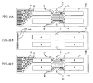
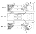
- Fig. 31A to 31C, Fig. 32A to 32C, and Fig. 33A to 33C, respectively, are plans of three plate-form members that configure different types of large cooling unit.
- the plate-form members that configure a large cooling unit (hereinafter called the fourth type large cooling unit) are described using Fig. 31A to 31C.
- a first plate-form member 87 as diagrammed in Fig. 31A, no inflow opening, outflow opening, intake opening, or outlet opening is provided.
- a second plate-form member 88 as diagrammed in Fig. 31B, has the same structure as the first plate-form member 79 (tenth embodiment) diagrammed in Fig. 30A.
- a third plate-form member 89 as diagrammed in Fig. 31C, has the same structure as the second plate-form member 80 diagrammed in Fig. 30B.
- the fourth type of large cooling unit is fabricated by mutually joining the first and third plate-form members 87 and 89 together so that the surfaces thereof whereon the grooves 33 have been formed contact the upper and lower surfaces, respectively, of the second plate-form member 88.
- the large cooling unit formed by these plate-form members 87, 88, and 89 there is no inflow opening 4, outflow opening 5, intake opening 8, or outlet opening 9 that passes all the way through.
- the plate-form members that configure a large cooling unit (hereinafter called the fifth type large cooling unit) are described using Fig. 32A to 32C.
- a first plate-form member 90 as diagrammed in Fig. 32A, no inflow opening, outflow opening, intake opening, or outlet opening is provided.
- a second plate-form member 91 as diagrammed in Fig. 32B, has the same structure as the second plate-form member 82 (tenth embodiment) diagrammed in Fig. 28B.
- a third plate-form member 92 as diagrammed in Fig. 32C, has the same structure as the third plate-form member 83 diagrammed in Fig. 28C.
- the fifth type large cooling unit is fabricated by mutually joining the first and third plate-form members 90 and 92 together so that the surfaces thereof whereon the grooves 33 have been formed contact the upper and lower surfaces, respectively, of the second plate-form member 91.
- the large cooling unit formed by these plate-form members 90, 91, and 92 there is no inflow opening 4, outflow opening 5, intake opening 8, or outlet opening 9 that passes all the way through.
- Fig. 33A to 33C the plate-form members that configure a large cooling unit (hereinafter called the sixth type large cooling unit) are described using Fig. 33A to 33C.
- a first plate-form member 93 as diagrammed in Fig. 33A, no inflow opening or outflow opening is provided.
- a second plate-form member 94 as diagrammed in Fig. 33B, has the same structure as the second plate-form member 82 (ninth embodiment) diagrammed in Fig. 28B.
- a third plate-form member 95 as diagrammed in Fig. 33C, has the same structure as the third plate-form member 83 diagrammed in Fig. 28C.
- the sixth type large cooling unit is fabricated by mutually joining the first and third plate-form members 93 and 95 together so that the surfaces thereof whereon the grooves 33 have been formed contact the upper and lower surfaces, respectively, of the second plate-form member 94.
- the large cooling unit formed by these plate-form members 93, 94, and 95 there is no inflow opening 4 or outflow opening 5 that passes all the way through.
- the fourth type large cooling unit (cf. Fig. 31A to 31C) described in the foregoing is used in a combination with the large cooling unit diagrammed in Figs. 30A and 30B.
- the fifth and sixth types of large cooling unit (cf. Fig. 32A to 32C and Fig. 33A to 33C) indicated above, on the other hand, are used in combinations with the large cooling unit diagrammed in Fig. 28A to 28C.
- These fourth, fifth, and sixth types of large cooling units are like the large cooling unit diagrammed in Fig. 28A to 28C and Fig. 30A and 30B in that they have no tightening bolt holes and in that the overall lengths thereof, respectively, are shorter.
- the fourth type large cooling unit (cf. Fig. 31A to 31C) can be used as the uppermost cooling device in the surface emitting device 74 diagrammed in Fig. 29A.
- the first plate-form member 87 (cf. Fig. 31A) configuring this large cooling unit will be on the upper side.
- the fourth type large cooling unit furthermore, can also be used as the uppermost cooling unit (whereupon the first plate-form member 87 will be on the upper side) and as the lowermost cooling unit (whereupon the first plate-form member 87 will be on the lower side) in the surface emitting device 75 diagrammed in Fig. 29B.
- the fifth type of large cooling unit (cf. Fig. 32A to 32C) can be used in the surface emitting device 75 diagrammed in Fig. 29B as the uppermost cooling unit (whereupon the first plate-form member 90 will be on the upper side) and as the lowermost cooling device (whereupon the first plate-form member 90 will be on the lower side).
- the sixth type large cooling unit (cf. Fig. 33A to 33C) can be used in the surface emitting device 71 diagrammed in Fig. 27 (ninth embodiment), whereupon, by being deployed in similar positions as the large cooling unit 53 diagrammed in Fig. 17, the inflow passages and outflow passages are definitely separated.
- a large cooling unit having the first plate-form member 93 on the lower side is deployed on a large cooling unit having the first plate-form member 93 on the upper side.
- cooling device As based on the cooling device relating to this embodiment, while holding down increases in the number of parts that constitutes a cause of increased costs to a minimum, more complete cooling liquid leakage protection is realized by using cooling units wherein unnecessary openings are closed, and it becomes possible to more definitely separate the inflow passages from the outflow passages, so that operational reliability is enhanced.
- Fig. 34A represents the condition of a surface emitting device 96 according to this embodiment prior to assembly, while Fig. 34B represents that surface emitting device 96 after it has been assembled.
- a supplemental tightening plate 97 used in the surface emitting device 96 is machined to a tapered shape so that it becomes slightly thinner toward the light-emitting surface side (the left side in Fig. 34B).
- the cooling device comprised by stacking together a plurality of the cooling units is subjected to a load in the direction of stacking by a weight applying device (not shown) and, in that loaded condition, the cooling device is pushed into a ring-shaped tightening belt 98 such as that diagrammed in Fig. 34A. After that, even when the weight of the weight applying device is removed, the cooling units that are stacked up in a plurality to configure the cooling device are held in a condition wherein pressure continues to be applied in the direction of stacking by the tightening belt 98.
- spacer parts 109 may be deployed on the inside side surfaces thereof as diagrammed in Fig. 34A and 34B.
- Fig. 35A represents the condition of a surface emitting device 99 according to this embodiment prior to assembly, while Fig. 35B represents that surface emitting device 99 after it has been assembled.
- two tightening belts 100 and 101 of a divided type having shapes corresponding to the outer shape of the cooling device are attached to the cooling device, which cooling device is made up of a plurality of stacked cooling units, and then that cooling device is subjected to a load in the direction of cooling unit stacking by a weight applying device (not shown). While the load is being placed on the cooling device by the weight applying device, the one tightening belt 100 and the other tightening belt 101 are mutually joined to form a ring shape. As a result, even after the load applied by the weight applying device is removed, the stacked cooling units will be held in a condition wherein pressure is applied in the stacking direction by the tightening belts 100 and 101 formed into the ring shape.
- the one tightening belt 100 and the other tightening belt 101 can be mutually joined by a method such as laser welding or electric welding, and when the belt material is a non-metal, an instantaneously acting bonding agent or the like can be used.
- the metal belts 101 and 101 are joined by welding (cf. weld 102).
- the required intensity of tightening on a cooling device made up of stacked cooling units is easily obtained without a tightening bolt, and a surface emitting device having few non-light-emitting parts as seen from the light-emitting surface side can be realized.
- the same tightening belts can be used for cooling devices of slightly different height, and a load can be placed on the entire surface of the cooling device by the weight applying device, wherefore very workable and reliable assembly operations are possible.
- Fig. 36A represents the condition of a surface emitting device 103 according to this embodiment prior to assembly, while Fig. 36B represents that surface emitting device 103 after it has been assembled.
- an outer protective container 104 having a width made even wider than the width of the divided type tightening belts 100 and 101 used in the embodiment diagrammed in Fig. 35A and 35B is used.
- This outer protective container 104 is provided, in the surface emitting device, on the light-emitting surface side, so that it sticks out further to the outside than that light-emitting surface.
- the weld 102 should be made near the bottom side of the surface emitting device for the sake of appearance.
- the divided fastening belts by making the divided fastening belts to double as an outer protective container for protecting the light-emitting element components, especially the laser bars, a surface emitting device having few non-light-emitting parts as seen from the light-emitting surface side, inclusive of the outer protective container, can be realized while reducing the danger of inadvertent damage during maintenance, etc.
- a surface-emitting light source equipped with an outer protective container can be obtained at lower cost.
- Fig. 37A represents the condition of a surface emitting device 105 according to this embodiment prior to assembly, while Fig. 37B represents that surface emitting device 105 after it has been assembled.
- grooves 106 are provided beforehand on the inside of the portion of the outer protective container 104 (14th embodiment) diagrammed in Fig. 36B that stick out further to the outside from the light-emitting surface of the surface emitting device. Then, using those grooves 106, when assembling the outer protective container 104, an optical member (cylindrical lens array 107) for collimating the first axes of the laser beams emitted from the plurality of laser bars into parallel light is mounted in front of the light-emitting surface, with good positional precision relative to the laser bars.
- an optical member for collimating the laser beams from the laser bars and converting them to parallel light can be installed with good positional precision by tightening belts that double as an outer protective container, whereupon a surface emitting device comprising a collimating optical system can be realized at low cost.
- All of the plate-form members that configure the large cooling units of the present invention have areas where the surface of the raw material metal plate remains unchanged, areas wherein holes such as inflow openings 4, outflow openings 5, tightening bolt holes 30, and guide pin holes 31, etc., are made to pass through, inclusive of the peripheries thereof, and areas where roughly half of the thickness of the plate-form members is dug out, such as for the inflow water passages 32 and outflow water passages 34.
- the photoresist is removed from both sides of the plate-form member in those areas where the member is to be completely done away with, while the photoresist is removed from only one side in those areas where roughly half of the thickness is to be dug out, then that plate-form member is immersed in an etching solution, whereupon, if the etching is terminated at a point in time where the etching depth has slightly exceeded the thickness of the plate-form member, a large cooling unit can be obtained with ease. Because of the size of the patterns, moreover, there is no need to perform special etching, and ordinary chemical etching of low process cost can be done.
- Fig. 38A to 38D are diagrammed plate-form members in the process of being manufactured, and cooling devices to which plate-form members are joined, taking as examples the cooling unit diagrammed in Fig. 8A to 8D and the large cooling unit diagrammed in Fig. 9A and 9B.
- plate-form members are formed from a metal plate constituting the raw material, in a condition wherein they are connected by plate-form member supporting bridges 108. These are stacked as they are, as diagrammed in Fig. 38D, heat and pressure are applied thereto, and they are joined together by diffusion welding or the like to yield a large cooling unit.
- the large cooling unit will be complete.
- the connecting metal plates and patterned insulating tapes may be mounted on the large cooling unit diagrammed in Fig. 38D, still connected to the stock plate by bridges with the same pitch, whereupon, after light-emitting element components are packaged and completed, all of the bridges may be cut away simultaneously.
- the large cooling units relating to the embodiments of the present invention can be manufactured in large volume at one time by ordinary chemical etching for which processing costs are low, making it possible to realize cost reductions in cooling devices and in surface emitting devices wherein such cooling devices are used.
- a cooling liquid induction port connected to an induction pipeline for inducting cooling liquid from a cooling liquid supply unit, and a cooling liquid discharge port connected to a discharge pipeline for returning the cooling liquid back to the cooling liquid supply unit.
- the cooling liquid induction port corresponds to the inflow openings in the large cooling units
- the cooling liquid discharge port corresponds to the outflow openings in the large cooling units.
- first tightening part and the second tightening part tighten the plurality of stacked cooling units, so that the gaps between the cooling units are reduced, with elastic spacer members interposed, so that cooling liquid does not leak from between the cooling units.
- Small cooling units are deployed so as to sandwich at least one large cooling unit, with at least one small cooling unit, respectively, deployed on each of the two sides thereof. Thereupon, an additional area is formed in that large cooling unit, at the back thereof, while, in the small cooling units, at positions corresponding to the additional area in the large cooling unit, extra space is formed, respectively.
- first and second tightening parts are deployed in those extra spaces.
- this first tightening part is provided a cooling liquid induction port that is connected to the induction pipeline. And, in this first tightening part, which occupies at least some of the extra space noted above, the cooling liquid induction port therein corresponds to the inflow openings in the large cooling units.
- the cooling liquid discharge port that is connected to the discharge pipeline. And, in this second tightening part, which occupies at least some of the extra space noted above, the cooling liquid discharge port therein corresponds to the outflow openings in the large cooling units.
- first tightening part and the second tightening part tighten the plurality of stacked cooling units, so that the gaps between the cooling units are reduced, with elastic spacer members interposed, so that cooling liquid does not leak from between the cooling units.
- tightening is done by a tightening belt from the outside of the plurality of stacked cooling units so that the gaps between the cooling units are reduced, with elastic spacer members interposed, so that the cooling liquid does not leak out from between those stacked cooling units.
- inflow openings and outflow openings for the cooling liquid are formed by a chemical etching method wherein resist patterns are used.
Landscapes
- Physics & Mathematics (AREA)
- Engineering & Computer Science (AREA)
- Thermal Sciences (AREA)
- Mechanical Engineering (AREA)
- General Engineering & Computer Science (AREA)
- Condensed Matter Physics & Semiconductors (AREA)
- General Physics & Mathematics (AREA)
- Electromagnetism (AREA)
- Optics & Photonics (AREA)
- Semiconductor Lasers (AREA)
Abstract
Description
(18) Small cooling units are deployed so as to sandwich at least one large cooling unit, with at least one small cooling unit, respectively, deployed on each of the two sides thereof. Thereupon, an additional area is formed in that large cooling unit, at the back thereof, while, in the small cooling units, at positions corresponding to the additional area in the large cooling unit, extra space is formed, respectively. Thereupon, first and second tightening parts are deployed in those extra spaces.
Claims (13)
- A cooling device wherein are stacked cooling units on which objects to be cooled are mounted, comprising:a first cooling liquid supply passage deployed so as to pass through first portions of said cooling units in order to conduct cooling liquid about periphery of each of said objects to be cooled;a cooling liquid discharge passage deployed so as to pass through second portions of said cooling units in order to discharge to outside of said cooling device said cooling liquid that has cooled each of said objects to be cooled; anda second cooling liquid supply passage that passes through third portions of said cooling units, and is connected to said first cooling liquid supply passage, wherewith said cooling liquid is supplied from outside.
- The cooling device according to claim 1, wherein said cooling units comprise:a first cooling unit wherein are provided two holes opening, respectively, to said first cooling liquid supply passage and said cooling liquid discharge passage; anda second cooling unit wherein are provided at least three holes opening, respectively, to said first cooling liquid supply passage, to said cooling liquid discharge passage, and also to said second cooling liquid supply passage.
- The cooling device according to claim 2, wherein said second cooling unit comprises a plurality of flow passages that connect said first cooling liquid supply passage and said second cooling liquid supply passage and that are partitioned by ridges.
- The cooling device according to claim 2 or 3, further comprising pressure bonding means for pressure bonding said stacked cooling units.
- The cooling device according to claim 4, wherein said pressure bonding means are a belt or belts that securely tighten said stacked cooling units.
- The cooling device according to any preceding claim, wherein a plurality of said cooling units are arranged in parallel, and further comprising a cooling liquid induction pipeline that is connected to all of said second cooling liquid supply passages contained in said cooling units which are arranged in parallel.
- The cooling device according to any preceding claim, further comprising a second cooling liquid discharge passage for discharging said cooling liquid to outside of said cooling device, said second cooling liquid discharge passage passing through fourth portions of said cooling units and being connected to said cooling liquid discharge passage.
- The cooling device according to any preceding claim, wherein said cooling units comprise:a first cooling unit having two holes opening, respectively, to said first cooling liquid supply passage and to said cooling liquid discharge passage;a second cooling unit having at least three holes opening, respectively, to said first cooling liquid supply passage, to said cooling liquid discharge passage, and also to said second cooling liquid supply passage; anda third cooling unit having at least three holes opening, respectively to said first cooling liquid supply passage, to said second cooling liquid supply passage, and also to said cooling liquid discharge passage which is connected to said cooling liquid discharge passage.
- The cooling device according to claim 7 or 8, wherein a plurality of said cooling units is arranged in parallel, and further comprising a cooling liquid discharge line that is connected to all of said second cooling liquid discharge passages comprised in said cooling units that are arranged in parallel.
- A surface emitting device having laser diode arrays mounted on cooling units which are themselves stacked; comprising:a first cooling liquid supply passage deployed so as to pass through first portions of said cooling units in order to conduct cooling liquid about the periphery of each of said laser diode arrays;a cooling liquid discharge passage deployed so as to pass through second portions of said cooling units in order to discharge to outside of said surface emitting device said cooling liquid that has cooled each of said laser diode arrays; anda second cooling liquid supply passage that passes through third portions of said cooling units, and is connected to said first cooling liquid supply passage, wherewith said cooling liquid is supplied from outside.
- The surface emitting device according to claim 10, further comprising a belt or belts that securely tighten said stacked cooling units.
- The surface emitting device according to claim 11, further comprising lenses deployed in opposition to the surface formed by said stacked laser diode arrays and held by said belt or belts.
- The surface emitting device of any one of claims 10 to 12, wherein each combination of first cooling liquid supply passage, cooling liquid discharge passage and second cooling liquid supply passage consists a cooling device according to any one of claims 1 to 10.
Applications Claiming Priority (2)
| Application Number | Priority Date | Filing Date | Title |
|---|---|---|---|
| JP21700799A JP3681581B2 (en) | 1999-07-30 | 1999-07-30 | Cooling device and surface light emitting device including the same |
| JP21700799 | 1999-07-30 |
Publications (2)
| Publication Number | Publication Date |
|---|---|
| EP1073167A2 true EP1073167A2 (en) | 2001-01-31 |
| EP1073167A3 EP1073167A3 (en) | 2006-04-19 |
Family
ID=16697373
Family Applications (1)
| Application Number | Title | Priority Date | Filing Date |
|---|---|---|---|
| EP00306511A Withdrawn EP1073167A3 (en) | 1999-07-30 | 2000-07-31 | Cooling device and surface emitting device comprising same |
Country Status (3)
| Country | Link |
|---|---|
| US (1) | US6643302B1 (en) |
| EP (1) | EP1073167A3 (en) |
| JP (1) | JP3681581B2 (en) |
Cited By (9)
| Publication number | Priority date | Publication date | Assignee | Title |
|---|---|---|---|---|
| WO2003031898A1 (en) | 2001-10-09 | 2003-04-17 | Mikros Manufacturing, Inc. | High heat flux single-phase heat exchanger |
| US6663596B2 (en) | 2001-08-13 | 2003-12-16 | Scimed Life Systems, Inc. | Delivering material to a patient |
| EP1284527A3 (en) * | 2001-07-24 | 2004-03-03 | Fanuc Ltd | Light source device for pumping solid-state laser medium |
| EP1271723A3 (en) * | 2001-06-25 | 2005-02-02 | Fanuc Ltd | Cooling device |
| WO2010020202A3 (en) * | 2008-06-05 | 2010-09-02 | Dirk Lorenzen | Apparatus with a semiconductor component-array and a cooling element |
| EP1271085B1 (en) * | 2001-06-23 | 2016-02-17 | MAHLE Behr GmbH & Co. KG | Device for cooling vehicle equipment, more particularly battery or fuel cell |
| CN112840514A (en) * | 2018-10-15 | 2021-05-25 | 松下知识产权经营株式会社 | Systems and methods for addressing thermal interface material pumping in high power laser systems |
| CN114284856A (en) * | 2021-12-16 | 2022-04-05 | 武汉点金激光科技有限公司 | Novel optical fiber coupling semiconductor laser and use method thereof |
| CN117628949A (en) * | 2024-01-25 | 2024-03-01 | 中国核动力研究设计院 | Microchannel cooling tower and welding frock thereof |
Families Citing this family (36)
| Publication number | Priority date | Publication date | Assignee | Title |
|---|---|---|---|---|
| WO2002035666A1 (en) * | 2000-10-20 | 2002-05-02 | Mitsubishi Denki Kabushiki Kaisha | Cooler, semiconductor laser light source, semiconductor laser light source unit, method for producing semiconductor laser light source unit, and solid laser |
| US7180100B2 (en) * | 2001-03-27 | 2007-02-20 | Ricoh Company, Ltd. | Semiconductor light-emitting device, surface-emission laser diode, and production apparatus thereof, production method, optical module and optical telecommunication system |
| US6917637B2 (en) * | 2001-10-12 | 2005-07-12 | Fuji Photo Film Co., Ltd. | Cooling device for laser diodes |
| US7187568B2 (en) | 2002-01-16 | 2007-03-06 | Rockwell Automation Technologies, Inc. | Power converter having improved terminal structure |
| US7177153B2 (en) | 2002-01-16 | 2007-02-13 | Rockwell Automation Technologies, Inc. | Vehicle drive module having improved cooling configuration |
| US7187548B2 (en) * | 2002-01-16 | 2007-03-06 | Rockwell Automation Technologies, Inc. | Power converter having improved fluid cooling |
| US6965514B2 (en) * | 2002-01-16 | 2005-11-15 | Rockwell Automation Technologies, Inc. | Fluid cooled vehicle drive module |
| US7142434B2 (en) * | 2002-01-16 | 2006-11-28 | Rockwell Automation Technologies, Inc. | Vehicle drive module having improved EMI shielding |
| US7061775B2 (en) | 2002-01-16 | 2006-06-13 | Rockwell Automation Technologies, Inc. | Power converter having improved EMI shielding |
| US6972957B2 (en) | 2002-01-16 | 2005-12-06 | Rockwell Automation Technologies, Inc. | Modular power converter having fluid cooled support |
| US6898072B2 (en) | 2002-01-16 | 2005-05-24 | Rockwell Automation Technologies, Inc. | Cooled electrical terminal assembly and device incorporating same |
| US7032695B2 (en) | 2002-01-16 | 2006-04-25 | Rockwell Automation Technologies, Inc. | Vehicle drive module having improved terminal design |
| DE10209374A1 (en) * | 2002-03-02 | 2003-07-31 | Rofin Sinar Laser Gmbh | Diode laser arrangement, e.g. for pumping solid state lasers, has series diode lasers with normally high impedance bypass elements for bridging diode lasers with high impedance defects |
| US6882331B2 (en) * | 2002-05-07 | 2005-04-19 | Jiahn-Chang Wu | Projector with array LED matrix light source |
| US20050084072A1 (en) * | 2003-10-17 | 2005-04-21 | Jmp Industries, Inc., An Ohio Corporation | Collimator fabrication |
| US8066955B2 (en) * | 2003-10-17 | 2011-11-29 | James M. Pinchot | Processing apparatus fabrication |
| US6994245B2 (en) * | 2003-10-17 | 2006-02-07 | James M. Pinchot | Micro-reactor fabrication |
| US7075959B1 (en) * | 2003-11-14 | 2006-07-11 | Hamilton Sundstrand Corporation | Cooling device for diode pumped laser |
| WO2005081371A2 (en) * | 2004-02-20 | 2005-09-01 | Electrovac Ag | Method for the production of stacks of plates, especially coolers or cooler elements composed of stacks of plates |
| JP4598422B2 (en) * | 2004-03-19 | 2010-12-15 | 浜松ホトニクス株式会社 | Laser array module and cooling manifold |
| JP4283738B2 (en) | 2004-07-08 | 2009-06-24 | 浜松ホトニクス株式会社 | Semiconductor laser device |
| US7215690B2 (en) * | 2004-08-04 | 2007-05-08 | Monocrom, S.L. | Laser module |
| DE102005033150A1 (en) * | 2005-07-13 | 2007-01-25 | Atotech Deutschland Gmbh | Microstructured cooler and its use |
| US20070291803A1 (en) * | 2006-06-15 | 2007-12-20 | Trevor Crum | Active Gas Cooling for Emitter Bars |
| CN101933202B (en) | 2007-12-17 | 2013-05-29 | 奥兰若光电公司 | Laser transmitter module and method of assembly |
| US8726976B2 (en) * | 2008-02-22 | 2014-05-20 | Liebert Corporation | Laminated sheet manifold for microchannel heat exchanger |
| JP5696298B2 (en) | 2008-05-08 | 2015-04-08 | ツー−シックス レーザー エンタープライズ ゲーエムベーハー | Method and device for high brightness diode output |
| US8737441B2 (en) * | 2009-08-31 | 2014-05-27 | Xi'an Focuslight Technologies Co., Ltd. | Cooling module for laser, fabricating method thereof, and semiconductor laser fabricated from the module |
| US8989226B2 (en) * | 2009-08-31 | 2015-03-24 | Xi'an Focuslight Technologies Co., Ltd. | Cooling module for laser, fabricating method thereof, and semiconductor laser fabricated from the module |
| JP5740654B2 (en) | 2010-01-22 | 2015-06-24 | トゥー−シックス レイザー エンタープライズ ゲーエムベーハー | Homogenization of far-field fiber-coupled radiation |
| US8401047B2 (en) | 2010-03-10 | 2013-03-19 | Panasonic Corporation | Semiconductor laser device |
| US8644357B2 (en) | 2011-01-11 | 2014-02-04 | Ii-Vi Incorporated | High reliability laser emitter modules |
| WO2017182005A1 (en) * | 2016-04-22 | 2017-10-26 | 西安炬光科技股份有限公司 | Refrigeration structure of semiconductor laser, and semiconductor laser and stack thereof |
| CN106785921A (en) * | 2016-12-29 | 2017-05-31 | 西安炬光科技股份有限公司 | A kind of semiconductor laser stacks of mechanical erection |
| CN112382916A (en) * | 2020-11-12 | 2021-02-19 | 扬州扬芯激光技术有限公司 | Heat sink and laser comprising same |
| CN120881955B (en) * | 2025-09-26 | 2025-12-05 | 辽宁和天精工科技有限公司 | A shock-resistant microchannel liquid cooling circulation system heat dissipation device |
Family Cites Families (10)
| Publication number | Priority date | Publication date | Assignee | Title |
|---|---|---|---|---|
| US4494171A (en) * | 1982-08-24 | 1985-01-15 | Sundstrand Corporation | Impingement cooling apparatus for heat liberating device |
| US5105429A (en) * | 1990-07-06 | 1992-04-14 | The United States Of America As Represented By The Department Of Energy | Modular package for cooling a laser diode array |
| US5099488A (en) | 1991-03-27 | 1992-03-24 | Spectra Diode Laboratories, Inc. | Ribbed submounts for two dimensional stacked laser array |
| US5125451A (en) * | 1991-04-02 | 1992-06-30 | Microunity Systems Engineering, Inc. | Heat exchanger for solid-state electronic devices |
| US5105430A (en) * | 1991-04-09 | 1992-04-14 | The United States Of America As Represented By The United States Department Of Energy | Thin planar package for cooling an array of edge-emitting laser diodes |
| DE4315580A1 (en) | 1993-05-11 | 1994-11-17 | Fraunhofer Ges Forschung | Arrangement comprising laser diodes and a cooling system, and method for its production |
| US5727618A (en) * | 1993-08-23 | 1998-03-17 | Sdl Inc | Modular microchannel heat exchanger |
| DE19506093C2 (en) * | 1995-02-22 | 2000-12-07 | Dilas Diodenlaser Gmbh | Diode laser device |
| JP3816194B2 (en) * | 1996-11-22 | 2006-08-30 | ファナック株式会社 | Cooling device, light source device, surface light emitting device, and manufacturing method thereof |
| US6192596B1 (en) * | 1999-03-08 | 2001-02-27 | Battelle Memorial Institute | Active microchannel fluid processing unit and method of making |
-
1999
- 1999-07-30 JP JP21700799A patent/JP3681581B2/en not_active Expired - Fee Related
-
2000
- 2000-07-27 US US09/627,095 patent/US6643302B1/en not_active Expired - Fee Related
- 2000-07-31 EP EP00306511A patent/EP1073167A3/en not_active Withdrawn
Cited By (13)
| Publication number | Priority date | Publication date | Assignee | Title |
|---|---|---|---|---|
| EP1271085B1 (en) * | 2001-06-23 | 2016-02-17 | MAHLE Behr GmbH & Co. KG | Device for cooling vehicle equipment, more particularly battery or fuel cell |
| EP1271723A3 (en) * | 2001-06-25 | 2005-02-02 | Fanuc Ltd | Cooling device |
| EP1284527A3 (en) * | 2001-07-24 | 2004-03-03 | Fanuc Ltd | Light source device for pumping solid-state laser medium |
| US6850549B2 (en) | 2001-07-24 | 2005-02-01 | Fanuc Ltd. | Light source device for pumping solid-state laser medium |
| US7270654B2 (en) | 2001-08-13 | 2007-09-18 | Boston Scientific Scimed, Inc. | Delivering material to a patient |
| US6663596B2 (en) | 2001-08-13 | 2003-12-16 | Scimed Life Systems, Inc. | Delivering material to a patient |
| EP1442266A4 (en) * | 2001-10-09 | 2007-05-23 | Mikros Mfg Inc | SINGLE-PHASE HEAT EXCHANGER WITH HIGH HEAT FLOW |
| WO2003031898A1 (en) | 2001-10-09 | 2003-04-17 | Mikros Manufacturing, Inc. | High heat flux single-phase heat exchanger |
| WO2010020202A3 (en) * | 2008-06-05 | 2010-09-02 | Dirk Lorenzen | Apparatus with a semiconductor component-array and a cooling element |
| CN112840514A (en) * | 2018-10-15 | 2021-05-25 | 松下知识产权经营株式会社 | Systems and methods for addressing thermal interface material pumping in high power laser systems |
| CN114284856A (en) * | 2021-12-16 | 2022-04-05 | 武汉点金激光科技有限公司 | Novel optical fiber coupling semiconductor laser and use method thereof |
| CN117628949A (en) * | 2024-01-25 | 2024-03-01 | 中国核动力研究设计院 | Microchannel cooling tower and welding frock thereof |
| CN117628949B (en) * | 2024-01-25 | 2024-04-09 | 中国核动力研究设计院 | Microchannel cooling tower and welding frock thereof |
Also Published As
| Publication number | Publication date |
|---|---|
| JP2001044555A (en) | 2001-02-16 |
| EP1073167A3 (en) | 2006-04-19 |
| US6643302B1 (en) | 2003-11-04 |
| JP3681581B2 (en) | 2005-08-10 |
Similar Documents
| Publication | Publication Date | Title |
|---|---|---|
| US6643302B1 (en) | Cooling device and surface emitting device comprising same | |
| US6865200B2 (en) | Cooling device | |
| US7058101B2 (en) | Stepped manifold array of microchannel heat sinks | |
| US7801190B2 (en) | Carrier for a vertical arrangement of laser diodes with a stop | |
| EP1253685B1 (en) | Cooling device, semiconductor laser light source device, and semiconductor laser light source unit | |
| EP3320587B1 (en) | Stepped diode laser module with cooling structure | |
| US6898222B2 (en) | Diode laser arrangement with a plurality of diode laser arrays | |
| US5903583A (en) | Diode laser component with cooling element and diode laser module | |
| EP0891630B1 (en) | Laser diode array packaging | |
| US6097744A (en) | Cooling device of a planar light source | |
| US20050141574A1 (en) | Cooling device for semiconductor component | |
| JP2001160649A (en) | Device for cooling diode laser | |
| JP5764152B2 (en) | Semiconductor laser device | |
| CA2285390A1 (en) | Semiconductor laser apparatus | |
| CN110783811A (en) | High-power module for surface-emitting laser chip | |
| US7271419B2 (en) | Laser device having a plurality of emission zones | |
| US11324148B2 (en) | Cooling system for power modules | |
| CN210838440U (en) | High-power module for surface-emitting laser chip | |
| US20220329048A1 (en) | System and method for laser diode array having integrated microchannel cooling | |
| JP2009064932A (en) | Laser array cooling device, laser module, and laser light source device | |
| KR101177564B1 (en) | Guide pin array device and method of manufacturing the same | |
| JP7536924B2 (en) | Electronic package and method for manufacturing electronic package - Patents.com | |
| CN114630554B (en) | Power electronic system with switching device and liquid cooling device | |
| US20200381894A1 (en) | Uniform Cooling of Laser Diode | |
| JP2006237630A (en) | Optical source device and surface light emitting device |
Legal Events
| Date | Code | Title | Description |
|---|---|---|---|
| PUAI | Public reference made under article 153(3) epc to a published international application that has entered the european phase |
Free format text: ORIGINAL CODE: 0009012 |
|
| AK | Designated contracting states |
Kind code of ref document: A2 Designated state(s): AT BE CH CY DE DK ES FI FR GB GR IE IT LI LU MC NL PT SE |
|
| AX | Request for extension of the european patent |
Free format text: AL;LT;LV;MK;RO;SI |
|
| RAP1 | Party data changed (applicant data changed or rights of an application transferred) |
Owner name: FANUC LTD |
|
| PUAL | Search report despatched |
Free format text: ORIGINAL CODE: 0009013 |
|
| AK | Designated contracting states |
Kind code of ref document: A3 Designated state(s): AT BE CH CY DE DK ES FI FR GB GR IE IT LI LU MC NL PT SE |
|
| AX | Request for extension of the european patent |
Extension state: AL LT LV MK RO SI |
|
| RIC1 | Information provided on ipc code assigned before grant |
Ipc: F28F 3/08 20060101ALI20060227BHEP Ipc: H01S 5/40 20060101ALI20060227BHEP Ipc: H01S 5/024 20060101AFI20001123BHEP |
|
| 17P | Request for examination filed |
Effective date: 20061016 |
|
| AKX | Designation fees paid |
Designated state(s): DE |
|
| 17Q | First examination report despatched |
Effective date: 20080417 |
|
| STAA | Information on the status of an ep patent application or granted ep patent |
Free format text: STATUS: THE APPLICATION IS DEEMED TO BE WITHDRAWN |
|
| 18D | Application deemed to be withdrawn |
Effective date: 20080828 |