EP1073059A1 - Method of press-working frame plate on which disk driving motor is arranged - Google Patents
Method of press-working frame plate on which disk driving motor is arranged Download PDFInfo
- Publication number
- EP1073059A1 EP1073059A1 EP00902950A EP00902950A EP1073059A1 EP 1073059 A1 EP1073059 A1 EP 1073059A1 EP 00902950 A EP00902950 A EP 00902950A EP 00902950 A EP00902950 A EP 00902950A EP 1073059 A1 EP1073059 A1 EP 1073059A1
- Authority
- EP
- European Patent Office
- Prior art keywords
- frame plate
- disk drive
- drive motor
- recess
- press molding
- Prior art date
- Legal status (The legal status is an assumption and is not a legal conclusion. Google has not performed a legal analysis and makes no representation as to the accuracy of the status listed.)
- Withdrawn
Links
Images




Classifications
-
- G—PHYSICS
- G11—INFORMATION STORAGE
- G11B—INFORMATION STORAGE BASED ON RELATIVE MOVEMENT BETWEEN RECORD CARRIER AND TRANSDUCER
- G11B3/00—Recording by mechanical cutting, deforming or pressing, e.g. of grooves or pits; Reproducing by mechanical sensing; Record carriers therefor
- G11B3/68—Record carriers
- G11B3/70—Record carriers characterised by the selection of material or structure; Processes or apparatus specially adapted for manufacturing record carriers
- G11B3/702—Record carriers characterised by the selection of material or structure; Processes or apparatus specially adapted for manufacturing record carriers for video discs with grooves
-
- G—PHYSICS
- G11—INFORMATION STORAGE
- G11B—INFORMATION STORAGE BASED ON RELATIVE MOVEMENT BETWEEN RECORD CARRIER AND TRANSDUCER
- G11B33/00—Constructional parts, details or accessories not provided for in the other groups of this subclass
- G11B33/12—Disposition of constructional parts in the apparatus, e.g. of power supply, of modules
- G11B33/121—Disposition of constructional parts in the apparatus, e.g. of power supply, of modules the apparatus comprising a single recording/reproducing device
-
- G—PHYSICS
- G11—INFORMATION STORAGE
- G11B—INFORMATION STORAGE BASED ON RELATIVE MOVEMENT BETWEEN RECORD CARRIER AND TRANSDUCER
- G11B19/00—Driving, starting, stopping record carriers not specifically of filamentary or web form, or of supports therefor; Control thereof; Control of operating function ; Driving both disc and head
- G11B19/20—Driving; Starting; Stopping; Control thereof
- G11B19/2009—Turntables, hubs and motors for disk drives; Mounting of motors in the drive
-
- G—PHYSICS
- G11—INFORMATION STORAGE
- G11B—INFORMATION STORAGE BASED ON RELATIVE MOVEMENT BETWEEN RECORD CARRIER AND TRANSDUCER
- G11B25/00—Apparatus characterised by the shape of record carrier employed but not specific to the method of recording or reproducing, e.g. dictating apparatus; Combinations of such apparatus
- G11B25/04—Apparatus characterised by the shape of record carrier employed but not specific to the method of recording or reproducing, e.g. dictating apparatus; Combinations of such apparatus using flat record carriers, e.g. disc, card
- G11B25/043—Apparatus characterised by the shape of record carrier employed but not specific to the method of recording or reproducing, e.g. dictating apparatus; Combinations of such apparatus using flat record carriers, e.g. disc, card using rotating discs
-
- G—PHYSICS
- G11—INFORMATION STORAGE
- G11B—INFORMATION STORAGE BASED ON RELATIVE MOVEMENT BETWEEN RECORD CARRIER AND TRANSDUCER
- G11B33/00—Constructional parts, details or accessories not provided for in the other groups of this subclass
- G11B33/02—Cabinets; Cases; Stands; Disposition of apparatus therein or thereon
-
- G—PHYSICS
- G11—INFORMATION STORAGE
- G11B—INFORMATION STORAGE BASED ON RELATIVE MOVEMENT BETWEEN RECORD CARRIER AND TRANSDUCER
- G11B5/00—Recording by magnetisation or demagnetisation of a record carrier; Reproducing by magnetic means; Record carriers therefor
- G11B5/74—Record carriers characterised by the form, e.g. sheet shaped to wrap around a drum
- G11B5/80—Card carriers
-
- H—ELECTRICITY
- H02—GENERATION; CONVERSION OR DISTRIBUTION OF ELECTRIC POWER
- H02K—DYNAMO-ELECTRIC MACHINES
- H02K15/00—Processes or apparatus specially adapted for manufacturing, assembling, maintaining or repairing of dynamo-electric machines
- H02K15/14—Casings; Enclosures; Supports
-
- H—ELECTRICITY
- H02—GENERATION; CONVERSION OR DISTRIBUTION OF ELECTRIC POWER
- H02K—DYNAMO-ELECTRIC MACHINES
- H02K5/00—Casings; Enclosures; Supports
- H02K5/04—Casings or enclosures characterised by the shape, form or construction thereof
-
- H—ELECTRICITY
- H02—GENERATION; CONVERSION OR DISTRIBUTION OF ELECTRIC POWER
- H02K—DYNAMO-ELECTRIC MACHINES
- H02K7/00—Arrangements for handling mechanical energy structurally associated with dynamo-electric machines, e.g. structural association with mechanical driving motors or auxiliary dynamo-electric machines
- H02K7/14—Structural association with mechanical loads, e.g. with hand-held machine tools or fans
Definitions
- the present invention relates to a method for press-molding a frame plate in order to mount a motor for driving a disk, for use as a storage medium, on the frame plate.
- a card-type magnetic recording device is inserted into a slot of a portable computer to add to the functions of the portable computer or increase the capacity of processing data.
- a casing of the card-type magnetic recording device is stored with various components, such as a disk-type storage medium, motor for rotating the storage medium, recording/reproducing head element for recording information in or reproducing information from the storage medium, mechanism for ejecting a cartridge stored with the disk from the casing, etc.
- the casing of the card-type magnetic recording device is composed of an upper cover, a lower cover, and a side frame.
- a circuit board for information processing is pasted on the lower surface of the frame plate.
- the external dimensions of the card-type magnetic recording device constructed in this manner are settled according to the PCMCIA (Personal Computer Memory Card International Association) standards.
- PCMCIA Personal Computer Memory Card International Association
- Type II of the PCMCIA standards which is conventionally used very often, the external dimensions of the card-type magnetic recording device (i.e., external dimensions of the casing) are set so that its width, length, and thickness are 54.0 mm, 85.60 mm, and the 5.0 mm, respectively.
- the disk drive motor and the recording/reproducing head element are attached individually to recesses that are formed in one frame plate.
- the disk drive motor and the recording/reproducing head element are mounted in the frame plate recesses in this manner, they can be fitted better in a space in the casing that is limited in height (thickness) than in the case where the frame plate is mounted on a flat surface, and the attachment is stabilized.
- a recess and a mounting hole for mounting the disk drive motor on the frame plate and a recess and a mounting hole for mounting the recording/reproducing head element are worked by press-molding a material.
- the material of the frame plate is a steel sheet or stainless-steel sheet. If the material is press-molded to form the mounting recesses and the mounting holes, therefore, pressing force cannot acts equally, owing to the elasticity of the material, and stress strain remains maldistributed on the press-molded frame plate. Practically, therefore, it is hard to obtain the shapes and dimensions of the mounting recesses and the mounting holes that are in conformity to target values.
- the object of the present invention is to provide a press molding method capable of accurately forming a recess and a mounting hole for locating a disk drive motor in a frame plate of an information device that stores a disk-shaped storage medium.
- a frame plate to be mounted with a disk drive motor is obtained by press molding in a manner such that a circular region is set on the frame plate, a motor mounting hole for mounting the disk drive motor is formed in the central portion of the circular region by punching, a recess with a circular cross section is formed by depressing the circular region in the direction of the cross section by backward extrusion molding, and a ring-shaped rising wall is formed around the motor mounting hole, the rising wall projecting in the direction of the cross section.
- the backward extrusion molding is applied to the formation of the recess for mounting the disk drive motor, so that the influence of deformation on various parts of the material during the molding process is small, and therefore, high-accuracy press molding can be accomplished.
- the motor can be mounted with an appropriate posture in a proper position on the frame plate.
- the ring-shaped rising wall is formed around the motor mounting hole that is formed in the center of the base of the recess.
- the press molding method of the present invention is a suitable press molding method for a frame plate of a thin small-sized device of which the external size is strictly standardized, e.g., a card-type magnetic recording device.
- PC card An outline of a card-type magnetic recording device 1, called a PC card, will first be described with reference to the external view of FIG. 1.
- This card-type magnetic recording device 1 has external dimensions according to Type II of the PCMCIA standards, and is constructed so that an external connector 6 is provided on the front part of a casing 5.
- the casing 5 is composed of an upper cover 2, a lower cover 3, and a side frame 7.
- the casing 5 has therein a space for holding a disk-type storage medium, and is stored with various components (mentioned later) that constitute the magnetic recording device 1.
- the card-type magnetic recording device 1 is connected to a portable computer (not shown) by means of the external connector 6.
- the card-type magnetic recording device 1 of FIG. 1 will now be described further in detail with reference to the exploded perspective view of FIG. 2.
- the upper cover 2 and the lower cover 3 are press-molded pieces of a thin SUS sheet, and the side frame 7 (front frame, rear frame, left-hand frame, and right-hand frame) is formed of a synthetic resin.
- a frame plate 8 of a stainless-steel sheet is formed integrally with the synthetic-resin side frame 7 by outsert molding.
- a space for holding a cartridge 17 that is stored with the magnetic recording disk is formed between the upper cover 2 and the frame plate 8.
- a motor for driving a disk 18, a recording/reproducing head element for recording information in or reproducing information from the disk 18, a mechanism for ejecting the cartridge 17 from the casing 5, and the like are mounted on the upper surface of the frame plate 8.
- a circuit board 13 is attached to the underside of the frame plate 8 with an insulating film 19 between them.
- the circuit board 13 is formed with a control circuit for driving a disk drive motor 10 (see FIG. 4) and a recording/reproducing head element 12 mounted on the upper surface of the frame plate 8, and a data processing circuit for reading and writing data through the recording/reproducing head element 12.
- the external connector 6 is connected to the front part of the circuit board 13.
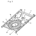
- the rear part of frame plate 8 is formed having a large recess 9 with a circular cross section in which the disk drive motor 10 (see FIG. 4) is to be located.
- the front part of the frame plate 8 is formed having a small recess 11 with a circular cross section in which the recording/reproducing head element 12 (FIG. 4) is to be located.
- a motor mounting hole 24 for fixing the shaft of the disk drive motor 10 is formed in the central portion of a base 33 of the recess 9 in which the motor 10 is to be located.
- the motor mounting hole 24 is surrounded by a rising wall 53.
- slots (coil relief holes) 52 which are as many as stator coils 20 (FIG. 4) of the motor 10 (or eighteen in number) and serve to receive the coils, are formed extending radially around the rising wall 53.
- eighteen distortion absorbing holes 28 are formed in the peripheral wall of the recess 9.
- arcuate ridges 49 are formed in three positions on the frame plate 8, extending along the outer peripheral portion of the recess 9.
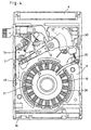
- FIG. 4 there will be described a state in which the various elements of the card-type magnetic recording device 1, including the disk drive motor 10, recording/reproducing head element 12, etc., are mounted on the frame shown in FIG. 3.
- the disk drive motor 10 is attached to the recess 9 (FIG. 3) that is formed in the rear part of the frame plate 8.
- the rotating shaft of the recording/reproducing head element 12 is supported by means of the recess 11 (FIG. 3) that is formed in the front part of the frame plate 8.
- the frame plate 8 carries thereon a main eject mechanism 14 and a sub-eject mechanism 15, which are mechanisms for ejecting the cartridge 17 (FIG. 2) from the casing 5.
- the disk drive motor 10 which is a thin flat structure, has eighteen radial stator coils 20 and a rotor 21 rotatable in its central portion.
- the rotor 21 has a ring magnet 22 on its upper surface, to which the hub of the magnetic recording disk 18 in the cartridge 17 is magnetically attracted when the cartridge 17 is inserted into the card-type magnetic recording device 1.
- a drive unit for the recording/reproducing head element 12 is composed of yokes 60, a driving coil 59 interposed between the yokes 60, a stator magnet (not shown), etc.
- FIGS. 5 to 16 there will be described steps of procedure for working the frame plate 8 in the form shown in FIG. 3, in which an external shape is stamped out from a flat sheet of stainless steel (SUS304, 0.4 mm thick) and a stamped sheet 23 thus obtained is subjected to press molding and punching.
- this working process may be based on a sequential-feed system (chain lines in FIG. 5 represent a carrier for sequential feed) in which a rolled sheet of SUS is rewound as it is completed by sequential feed and a single-action system in which stamped sheets, called blanks, are worked individually, the working methods have no substantial differences.
- a circular region 25 for forming the recess 9 for mounting the disk drive motor 10 is set in a position on the stamped sheet 23 on the rear side (right-hand side in FIG. 5) of its center.
- the motor mounting hole 24 is punched out in the central portion of the circular region 25.
- the motor mounting hole 24 serves to receive and fix the shaft portion of the disk drive motor 10.
- the hole 24 is a roughly punched hole that has a radius about 0.2 mm smaller than a designed dimension and leaves a finish allowance for fine punching in a subsequent process (fifth process mentioned later).
- the eighteen distortion absorbing holes 28 are formed at equal spaces in the circumferential direction along the boundary (circle) of the circular region 25 on the stamped sheet 23.
- a region between each two adjacent distortion absorbing holes 28 serves as a bridge portion 29 for backward extrusion in a process of press molding mentioned later.
- the formation of the distortion absorbing holes 28 may be carried out simultaneously with the formation (rough punching) of the motor mounting hole 24.
- a circular region 30 for forming the recess 11 for mounting the rotating shaft of the recording/reproducing head element 12 is set in a position on the stamped sheet 23 on the front side of its center. Further, eight distortion absorbing holes 31 are formed at equal spaces in the circumferential direction along the boundary (circle) of the circular region 230 on the stamped sheet 23. A region between each two adjacent distortion absorbing holes 31 serves as a bridge portion 32 in the process of press molding mentioned later.
- the stamped sheet 23 is formed with apertures 26a, 26b, 26c and 26d for mounting various small components, holes 26e through which positioning pins used in each process pass, individually, and punched portions 27a, 27b, 27c and 27d for the formation of raised portions.
- the apertures 26a to 26d, holes 26e, and punched portions 27a to 27d are formed before the motor mounting hole 24 is roughly punched.
- a member represented by chain lines c is a carrier of the stamped sheet 23.
- the recesses 9 and 11 are formed by press-molding the circular regions 25 and 30 set on the stamped sheet 23 by means of a press tool for backward extrusion that includes a die 35 and a punch 37. This press molding will be described with reference to FIG. 11.
- the stamped sheet 23 is placed on the upper surface of the die 35, and moreover, the upper surface of the stamped sheet 23 is pressed by means of a stripper 36. That region of the stamped sheet 23 which is expected to form the base of the recess 9 or 11 is pushed in downward (in the direction indicated by arrow A in FIG. 11) with respect to the die 35 in a manner such that it is held between the punch 37 and a knockout punch 38.
- the respective opposed side faces of the die 35 and the punch 37 are slopes (i.e., shoulder portions 39 and 40), not vertical surfaces. If the punch 37 is pushed in the direction indicated by arrow A in FIG. 11 with respect to the die 35, therefore, the bridge portions 29 between the distortion absorbing holes 28 or the bridge portions 32 between the distortion absorbing holes 31 of the stamped sheet 23 are crushed between the shoulder portion 39 of the the 35 and the shoulder portion 40 of the punch 37 and subjected to backward extruding action.
- the bridge portions 29 or 32 of the stamped sheet 23 crushed by the shoulder portions 39 and 40 extend in the direction of arrow B of FIG. 11 and the direction of arrow C opposite to it (in the moving direction of the punch 37 and its opposite direction) and form the peripheral wall of the recess 9 or 11.
- the distortion absorbing holes 28 or 31 extend in the directions of arrows C and D (i.e., in the depth direction of the recess 9 or 11) and are deformed.
- the press molding for backward extrusion is applied in this manner, the circular regions 25 and 30 set on the stamped sheet 23 are depressed in the direction of its cross section by the aforesaid press molding. Deformation that is caused by this depression is compensated as the material is stretched by the press molding, so that the areas around the circular regions 25 and 30 of the frame plate of the stamped sheet 23 undergo no deformation during molding operation.
- This press molding is performed within a limited volume and is finished in one process.
- the form of the recess 9 or 11 is rearranged by press molding using a die 41, stripper 42, and knockout punch 43 shown in FIG. 12.
- the stamped sheet 23 is placed on the die that has no slope (shoulder portion), and its top is held down by means of the stripper 42 that has no slope (shoulder portion). Then, the stamped sheet 23 is pressed by lifting the knockout punch 43 that is placed on the underside of the bottom 33 of the recess 9 or the base of the recess 11 (i.e., by moving it toward the stripper). In consequence, the recess 9 or the recess 11 is formed having a vertical peripheral wall. The vertical peripheral wall of the recess 9 or 11 is provided with the distortion absorbing holes 28 or 31 that extend deformed in the depth direction.
- the recess 9 or the recess 11, which is formed by subjecting the stamped sheet 23 to the press molding using the die 35 and the punch 37 shown in FIG. 11 (second process) and then subjecting it to the press molding using the die 41 and the knockout punch 43 shown in FIG. 12 (third process), is a high-precision recess having corner portions 44 and 45 that bend at right angles.
- Left- and right-hand side walls 46a and 46b of the stamped sheet 23 is raised. Further, a step portion 47 is formed on the front end of the stamped sheet 23. Furthermore, a raised portion 48 is formed on a part of the rear end of the stamped sheet 23.
- three arcuate ridges 49 are arranged around and along the disk drive motor mounting recess 9 of the stamped sheet 23. Furthermore, a portion 50 that serves as a bearing of the sub-eject mechanism 15 (FIG. 4), a spot 51 that serves as a mounting portion for a small component, etc. are formed in given regions on the stamped sheet 23 by burring.
- the motor mounting hole 24 (the outline of the hole 24 is represented by two-dot chain line in FIG. 8) is formed by rough punching in the central portion of the circular region 25 of the stamped sheet 23.
- finish working fine punching
- This fine punching involves a finish allowance (about 0.5 mm) for a subsequent burring finish process.
- This fine punching is applied to the bottom 33 of the disk drive motor mounting recess 9.
- the recess 9 is already formed before the present process is started. Accordingly, causes of distortion, such as knurls remaining on the stamped sheet 23, are already removed when the recess 9 is formed, so that the motor mounting hole 24 can be formed accurately.
- each coil relief slot 52 is located so as to face the point halfway between each corresponding distortion absorbing hole 28 and its adjacent distortion absorbing hole 28 (these holes 28 are already formed in the first process).
- the fine punching of the motor mounting hole 24 and the punching of the coil relief slots 52 may be carried out simultaneously.
- the eighteen coil relief slots 52 are radially formed at equal spaces in the circumferential direction in the bottom 33 of the disk drive motor mounting recess 9.
- the eighteen slots 52 are punched in two installments of nine without being all punched at a stroke as a piercing die moves, so that the coil relief slots 52 can be formed without requiring a great force at a time.
- the bottom 33 of the recess 9 is subjected to a smaller shock, so that distortion of the recess 9 that is caused by piercing can be restrained.
- the eighteen coil relief slots 52 are alternately punched in two installments of nine, so that the bottom 33 of the recess 9 cannot be subjected, in these two cycles of punching, to any one-sided force in any direction such that it is deformed. It is to be understood that every third slot may be punched so that the slots are divided in three installments of six.
- the eighteen slots 52 formed in the bottom 33 of the recess 9 are not opposed to the eighteen distortion absorbing holes 28 in a peripheral wall 34 (see FIG. 13) of the recess 9, and each faces the point halfway between each corresponding distortion absorbing hole 28 and its adjacent distortion absorbing hole 28. In consequence, that region of the recess 9 which is located between the distortion absorbing holes 28 and the coil relief slots 52 is not specially narrowed, so that there is no possibility of that region being deformed by an external force.
- a cutout hole 61 is formed in the front part of the stamped sheet 23.
- the cutout hole 61 can be fitted with the yokes 60 (FIG. 4), which constitute the drive unit for the recording/reproducing head element 12, and the stator magnet.
- the yokes 60 and stator magnet should be attached to the cutout hole 61 in this manner because the stamped sheet 23 (which forms the frame plate 8 when worked) is formed of a stainless-steel sheet, a nonmagnetic material, which, though thin, has relatively high stiffness.
- the yokes 60 molded from a magnetic steel sheet, are attached to the cutout hole 61, and a permanent magnet for use as a stator is located on the yokes 60.
- Support projections 62 are formed on the front part of the stamped sheet 23 by supplementary hammering. These support projections 62 serve to support the cartridge 17 that is inserted in the card-type magnetic recording device 1 (FIG. 1) so that the disk drive motor 10 is not damaged when the cartridge 17 is pressed through the upper cover 2.
- the punched portions 27a to 27c (FIG. 5) formed before the first process are raised (bent) to form risers, and a small piece of the punched portion 27d is turned (bent) to form a riser.
- the rising wall 53 (see FIG. 13) is formed around the motor mounting hole 24 by burring.
- the rising wall 53 is in the form of a ring, which projects vertically from the plane of the bottom 33 of the disk drive motor mounting recess 9.
- the burring serves to correct deformation of the recess 9 that may possibly be caused when the coil relief slots 52 are punched out in the preceding processes (fifth and sixth processes) and maintain the corrected form of the recess 9.
- the burring is carried out by using a die 54, stripper 55, knockout punch 56, punch 57, and insert die 58.
- a clearance s that is equivalent to the thickness of the bottom 33 of the recess 9 is provided between the stripper 55 and the insert die 58.
- the punch 57 is provided with an annular protrusion 57' that projects downward.
- the protrusion 57' has a wall thickness such that it can get into the clearance s between the stripper 55 and the insert die 58.
- the burring is carried out in two steps, rough bending (FIG. 14) and fine bending (FIGS. 15 and 16). The following is a description of these steps.
- the stamped sheet 23 is formed into the frame plate shown in FIG. 3 after undergoing the various processes described above.
- the card-type magnetic recording device 1 is assembled substantially in the following manner.
- the disk drive motor 10 is attached to the recess 9 of the frame plate 8, and the disk drive motor 10 and the circuit board 13 are connected to each other.
- the stator coils 20 of the disk drive motor 10 are fitted individually in the coil relief slots 42 that are formed in the recess 9.
- the recording/reproducing head element 12 is attached to the recess 11 of the frame plate 8.
- the driving coil 59 is interposed between the yokes 60 that are fixed to the frame plate 8.
- main eject mechanism 14, sub-eject mechanism 15, and other components are attached to the frame plate 8.
- the circuit board 13 is put on and fixed to the underside of the frame plate.
- the upper and lower covers 2 and 3 are caused to engage the side frame 7 to form the casing 5.
- the card-type magnetic recording device 1 is completed in which a socket of the external connector 6 is exposed forward, and which is provided with an aperture (having the shutter 16) for the insertion of the cartridge 17 at the rear end.
- the card-type magnetic recording device 1 has been described as a device of which the external size is based on Type II of the PCMCIA standards, the press molding method for the frame plate according to the present invention is not limited to these standard and type.
Landscapes
- Engineering & Computer Science (AREA)
- Power Engineering (AREA)
- Manufacturing & Machinery (AREA)
- Multimedia (AREA)
- Manufacture Of Motors, Generators (AREA)
- Motor Or Generator Frames (AREA)
- Shaping Metal By Deep-Drawing, Or The Like (AREA)
- Rotational Drive Of Disk (AREA)
Abstract
Description
Claims (18)
- A press molding method for a frame plate to be mounted with a disk drive motor, comprising:setting a circular region on the frame plate;forming a motor mounting hole for mounting the disk drive motor in the central portion of said circular region by punching;forming a recess with a circular cross section by depressing said circular region in the direction of the cross section by backward extrusion molding; andforming a ring-shaped rising wall around said motor mounting hole, said rising wall projecting in the direction of the cross section.
- A press molding method for a frame plate to be mounted with a disk drive motor according to claim 1, which further comprises forming a plurality of coil relief slots for the location of stator coils in the bottom of said formed recess, said slots being arranged radially at equal spaces around the center of said base.
- A press molding method for a frame plate to be mounted with a disk drive motor according to claim 2, wherein said plurality of coil relief slots are formed by a plurality of cycles of punching.
- A press molding method for a frame plate to be mounted with a disk drive motor according to claim 1, wherein the formation of said recess is preceded by forming, by punching, a plurality of distortion absorbing holes at equal spaces in the circumferential direction along the boundary of the region to be formed with said recess so that regions between the adjacent distortion absorbing holes serve as bridge portions for backward extrusion.
- A press molding method for a frame plate to be mounted with a disk drive motor according to claim 4, wherein each said distortion absorbing hole is located so as to face the point halfway between each said distortion absorbing hole and the distortion absorbing holes adjacent thereto.
- A press molding method for a frame plate to be mounted with a disk drive motor according to claim 1, wherein said forming the motor mounting hole by punching includes rough punching for forming a first aperture in the central portion of the circular region and fine punching following the formation of said recess.
- A press molding method for a frame plate to be mounted with a disk drive motor according to claim 6, wherein said rough punching is carried out simultaneously with the punching of said distortion absorbing holes.
- A press molding method for a frame plate to be mounted with a disk drive motor according to claim 6, wherein said fine punching is carried out simultaneously with the punching of said coil relief slots.
- A press molding method for a frame plate to be mounted with a disk drive motor according to claim 1, wherein said ring-shaped rising wall is formed by burring.
- A press molding method for a frame plate to be mounted with a disk drive motor according to claim 9, wherein said burring includes two steps, rough bending and fine bending.
- A press molding method for a frame plate to be mounted with a disk drive motor according to claim 9, wherein the direction of bending by said burring is opposite to the direction of depression for the formation of the recess in the direction of the cross section.
- A press molding method for a frame plate to be mounted with a disk drive motor according to claim 1, wherein a second recess with a circular cross section for the location of a rotating shaft portion of a recording/reproducing head element is formed in said frame plate by backward extrusion molding as said recess is formed.
- A press molding method for a frame plate to be mounted with a disk drive motor according to claim 1, wherein said backward extrusion molding is carried out by applying press molding using a die and a punch having a slope each to a material sheet for the frame plate.
- A press molding method for a frame plate to be mounted with a disk drive motor, comprising:setting a circular region on the frame plate;simultaneously forming a motor mounting hole for mounting the disk drive motor in the central portion of the circular region and a motor mounting hole for mounting the disk drive motor on the boundary of the circular region by punching;forming a recess with a circular cross section by depressing said circular region in the direction of the cross section by backward extrusion molding;simultaneously forming a fine motor mounting hole and coil relief slots by punching; andforming a ring-shaped rising wall around said fine motor mounting hole, said rising wall projecting in the direction of the cross section.
- A press molding method for a frame plate to be mounted with a disk drive motor according to claim 14, wherein a second recess with a circular cross section for the location of a rotating shaft portion of a recording/reproducing head element is formed in said. frame plate by backward extrusion molding as said recess is formed.
- A press molding method for a frame plate to be mounted with a disk drive motor according to claim 12 or 15, wherein said second recess with a circular cross section is formed by setting a circular region on said frame plate, forming a plurality of distortion absorbing holes at equal spaces on the boundary of said circular region so that the regions between the adjacent distortion absorbing holes serve as bridge portions for backward extrusion, and depressing the circular region in the direction of the cross section by backward extrusion molding.
- A press molding method for a frame plate to be mounted with a disk drive motor according to claim 14, wherein said backward extrusion molding is carried out by applying press molding using a die and a punch having a slope each to a material sheet for the frame plate.
- A press molding method for a frame plate to be mounted with a disk drive motor according to claim 13 or 17, wherein said material sheet is gradually press-molded to complete the frame plate to be mounted with the disk drive motor in a manner such that a rolled sheet is rewound as the sheet is fed sequentially.
Applications Claiming Priority (3)
| Application Number | Priority Date | Filing Date | Title |
|---|---|---|---|
| JP4073599 | 1999-02-19 | ||
| JP11040735A JP2000245122A (en) | 1999-02-19 | 1999-02-19 | Press processing method of frame plate on which disk motor is arranged |
| PCT/JP2000/000796 WO2000049620A1 (en) | 1999-02-19 | 2000-02-14 | Method of press-working frame plate on which disk driving motor is arranged |
Publications (2)
| Publication Number | Publication Date |
|---|---|
| EP1073059A1 true EP1073059A1 (en) | 2001-01-31 |
| EP1073059A4 EP1073059A4 (en) | 2004-10-27 |
Family
ID=12588902
Family Applications (1)
| Application Number | Title | Priority Date | Filing Date |
|---|---|---|---|
| EP00902950A Withdrawn EP1073059A4 (en) | 1999-02-19 | 2000-02-14 | Method of press-working frame plate on which disk driving motor is arranged |
Country Status (6)
| Country | Link |
|---|---|
| US (1) | US6389869B1 (en) |
| EP (1) | EP1073059A4 (en) |
| JP (1) | JP2000245122A (en) |
| KR (1) | KR20010052262A (en) |
| CN (1) | CN1159721C (en) |
| WO (1) | WO2000049620A1 (en) |
Families Citing this family (22)
| Publication number | Priority date | Publication date | Assignee | Title |
|---|---|---|---|---|
| DE69915193T2 (en) * | 1998-03-20 | 2004-09-16 | Citizen Watch Co., Ltd., Nishitokyo | MAGNETIC RECORDING DEVICE |
| US7146713B1 (en) | 2000-08-16 | 2006-12-12 | Cheung Woh Metal Works (Pte) Ltd. | Method of manufacturing a base plate |
| US20040134253A1 (en) * | 2003-01-13 | 2004-07-15 | Kim David K. | Apparatus and methods for providing controlled shapes during stamping process of computer system enclosures |
| DE10301872B3 (en) * | 2003-01-17 | 2004-03-11 | Linde & Wiemann Gmbh Kg | Sheet metal automobile airbag cover manufacturing method provides loops between peripheral frame and central region by bending material strips with overlapping of frame arms for length compensation |
| US6942491B2 (en) * | 2003-08-12 | 2005-09-13 | Adc Telecommunications, Inc. | Triaxial bulkhead connector |
| US7546669B1 (en) * | 2004-06-08 | 2009-06-16 | Cheung Woh Technologies Ltd. | Progressive and transfer die stamping |
| SG122845A1 (en) * | 2004-12-01 | 2006-06-29 | Metalform Asia Pte Ltd | Method of fabricating a workpiece form a sheet of material |
| SG122868A1 (en) * | 2004-12-01 | 2006-06-29 | Metalform Asia Pte Ltd | Method of fabricating a workpiece from a sheet of material |
| JP4023746B2 (en) * | 2005-02-23 | 2007-12-19 | 日本発条株式会社 | Base for hard disk drive and manufacturing method |
| US7760464B2 (en) * | 2005-09-08 | 2010-07-20 | Seagate Technology Llc | Base for data storage device with parallelism mounting features |
| JP2007098409A (en) * | 2005-09-30 | 2007-04-19 | Toshiba Corp | Sheet material cutting method, mold, printed circuit board, and electronic device |
| JP2007275976A (en) * | 2006-04-11 | 2007-10-25 | Fujifilm Corp | Press mold, burring processing method, manufacturing method of pressed product, and pressed product |
| JP5878026B2 (en) * | 2011-09-28 | 2016-03-08 | 盛岡セイコー工業株式会社 | Pressed part and method for manufacturing pressed part |
| KR20130066800A (en) * | 2011-12-13 | 2013-06-21 | 삼성전기주식회사 | Base plate for hard disk drive and hard disk drive including the same |
| US9481932B2 (en) | 2012-04-26 | 2016-11-01 | Cheung Woh Technologies Ltd. | Method and apparatus for progressively forging a hard disk drive base plate |
| KR101422955B1 (en) * | 2012-12-20 | 2014-07-23 | 삼성전기주식회사 | Base assembly and driving device of recording disk having the same |
| US8797679B1 (en) * | 2013-02-04 | 2014-08-05 | Seagate Technology Llc | Multipiece deck for hard disk drive |
| CN104103282A (en) | 2013-04-05 | 2014-10-15 | 三星电机株式会社 | Base for disk driving device |
| CN103292149A (en) * | 2013-06-21 | 2013-09-11 | 苏州新区枫桥净化设备厂 | Rack board |
| KR101525708B1 (en) * | 2013-12-30 | 2015-06-03 | 삼성전기주식회사 | Base for hard disk drive and hard disk drive including the same |
| CN105448308B (en) | 2014-08-27 | 2019-04-09 | 祥和科技有限公司 | It is used to form the method and apparatus with the hard disk drive substrate for extending height |
| CN104609280A (en) * | 2015-03-05 | 2015-05-13 | 苏州市汉诺威升降台有限公司 | Machine frame plate of lifting machine |
Family Cites Families (8)
| Publication number | Priority date | Publication date | Assignee | Title |
|---|---|---|---|---|
| US4741194A (en) * | 1986-09-25 | 1988-05-03 | The Budd Company | Composite rotor manufacturing method |
| JPH02137620A (en) * | 1988-11-17 | 1990-05-25 | Tokin Corp | Metallic spacer and its working method |
| US5329412A (en) * | 1990-06-01 | 1994-07-12 | Conner Peripherals, Inc. | Two and one half inch diameter disk drive having 0.6 inch height |
| JPH08153386A (en) | 1994-11-28 | 1996-06-11 | Minebea Co Ltd | Hard disk drive base manufacturing method |
| JP2863908B2 (en) | 1995-10-26 | 1999-03-03 | ミネベア株式会社 | Hard disk drive device and method of manufacturing the same |
| DE19540294C2 (en) * | 1995-10-28 | 1997-08-14 | Fichtel & Sachs Ag | Hydrodynamic torque converter with passage in the housing cover |
| IT1297735B1 (en) * | 1997-11-28 | 1999-12-20 | Attrezzeria Mv & C Snc | DRAWING AND COINING MOLD FOR THE MANUFACTURE OF METALLIC CONTAINERS AND SIMILAR |
| KR20010012800A (en) * | 1998-03-20 | 2001-02-26 | 하루타 히로시 | magnetic recording device |
-
1999
- 1999-02-19 JP JP11040735A patent/JP2000245122A/en not_active Ceased
-
2000
- 2000-02-14 CN CNB008001871A patent/CN1159721C/en not_active Expired - Fee Related
- 2000-02-14 US US09/673,627 patent/US6389869B1/en not_active Expired - Fee Related
- 2000-02-14 WO PCT/JP2000/000796 patent/WO2000049620A1/en not_active Ceased
- 2000-02-14 EP EP00902950A patent/EP1073059A4/en not_active Withdrawn
- 2000-02-14 KR KR1020007011583A patent/KR20010052262A/en not_active Ceased
Also Published As
| Publication number | Publication date |
|---|---|
| EP1073059A4 (en) | 2004-10-27 |
| US6389869B1 (en) | 2002-05-21 |
| KR20010052262A (en) | 2001-06-25 |
| CN1294741A (en) | 2001-05-09 |
| CN1159721C (en) | 2004-07-28 |
| JP2000245122A (en) | 2000-09-08 |
| WO2000049620A1 (en) | 2000-08-24 |
Similar Documents
| Publication | Publication Date | Title |
|---|---|---|
| US6389869B1 (en) | Pressing method for frame plate to be mounted with disk drive motor | |
| EP0298748A2 (en) | Magnetic disk apparatus | |
| HU215304B (en) | Rotating disk data storage device | |
| CN103516095B (en) | Substrate, base unit, motor and disk drive device | |
| US20060130089A1 (en) | Disk drive | |
| US5731934A (en) | Stacked arms assembled in a head disk assembly | |
| EP0668653A1 (en) | Magnetic circuit structure in disk unit | |
| JPH1024343A (en) | Manufacturing method of bottomed container | |
| CN101908350B (en) | Turntable and method of manufacturing the turntable | |
| US5396390A (en) | Magnetic head assembly for floppy disc drive | |
| US5585679A (en) | One-piece magnet return path assembly for a disk drive actuator | |
| US20060206909A1 (en) | Thin brushless motor | |
| JPH077587B2 (en) | Flotpie disk processing method | |
| KR100449928B1 (en) | Shutter for disc cartridges with integral display | |
| CN1191583C (en) | magnetic recording device | |
| KR101452075B1 (en) | Base plate and disc driving device including the same | |
| US20060221493A1 (en) | Coined features including material flow openings | |
| CN119585977A (en) | Motor and method for manufacturing iron core | |
| JP2001037111A (en) | Laminated core and method of manufacturing the same | |
| JP2001518652A (en) | Electronic card | |
| JP2775802B2 (en) | Information disk holding device | |
| JP3029813B2 (en) | Tool for taking out information recording media | |
| KR100255059B1 (en) | Contact point structure | |
| US20040080870A1 (en) | Disc cartridge and method of producing the same | |
| JPH077586B2 (en) | Flotpie disk processing method |
Legal Events
| Date | Code | Title | Description |
|---|---|---|---|
| PUAI | Public reference made under article 153(3) epc to a published international application that has entered the european phase |
Free format text: ORIGINAL CODE: 0009012 |
|
| 17P | Request for examination filed |
Effective date: 20001114 |
|
| AK | Designated contracting states |
Kind code of ref document: A1 Designated state(s): AT BE CH CY DE DK ES FI FR GB GR IE IT LI LU MC NL PT SE |
|
| RAP1 | Party data changed (applicant data changed or rights of an application transferred) |
Owner name: CITIZEN WATCH CO. LTD. Owner name: KABUSHIKI KAISHA KATSUMATA HATSUJYO SEISAKUSHO |
|
| RBV | Designated contracting states (corrected) |
Designated state(s): DE FR GB IT |
|
| RIC1 | Information provided on ipc code assigned before grant |
Ipc: 7G 11B 33/02 B Ipc: 7H 02K 15/14 B Ipc: 7G 11B 25/04 B Ipc: 7G 11B 33/12 A |
|
| A4 | Supplementary search report drawn up and despatched |
Effective date: 20040910 |
|
| RAP1 | Party data changed (applicant data changed or rights of an application transferred) |
Owner name: KABUSHIKI KAISHA KATSUMATA HATSUJYO SEISAKUSHO Owner name: CITIZEN HOLDINGS CO., LTD. |
|
| STAA | Information on the status of an ep patent application or granted ep patent |
Free format text: STATUS: THE APPLICATION IS DEEMED TO BE WITHDRAWN |
|
| 18D | Application deemed to be withdrawn |
Effective date: 20070829 |