EP1072804A2 - Magnetic bearing device - Google Patents
Magnetic bearing device Download PDFInfo
- Publication number
- EP1072804A2 EP1072804A2 EP00306103A EP00306103A EP1072804A2 EP 1072804 A2 EP1072804 A2 EP 1072804A2 EP 00306103 A EP00306103 A EP 00306103A EP 00306103 A EP00306103 A EP 00306103A EP 1072804 A2 EP1072804 A2 EP 1072804A2
- Authority
- EP
- European Patent Office
- Prior art keywords
- shaft
- magnetic bearing
- rotating member
- stator
- disk
- Prior art date
- Legal status (The legal status is an assumption and is not a legal conclusion. Google has not performed a legal analysis and makes no representation as to the accuracy of the status listed.)
- Withdrawn
Links
Images




Classifications
-
- F—MECHANICAL ENGINEERING; LIGHTING; HEATING; WEAPONS; BLASTING
- F16—ENGINEERING ELEMENTS AND UNITS; GENERAL MEASURES FOR PRODUCING AND MAINTAINING EFFECTIVE FUNCTIONING OF MACHINES OR INSTALLATIONS; THERMAL INSULATION IN GENERAL
- F16C—SHAFTS; FLEXIBLE SHAFTS; ELEMENTS OR CRANKSHAFT MECHANISMS; ROTARY BODIES OTHER THAN GEARING ELEMENTS; BEARINGS
- F16C32/00—Bearings not otherwise provided for
- F16C32/04—Bearings not otherwise provided for using magnetic or electric supporting means
- F16C32/0406—Magnetic bearings
- F16C32/044—Active magnetic bearings
-
- F—MECHANICAL ENGINEERING; LIGHTING; HEATING; WEAPONS; BLASTING
- F16—ENGINEERING ELEMENTS AND UNITS; GENERAL MEASURES FOR PRODUCING AND MAINTAINING EFFECTIVE FUNCTIONING OF MACHINES OR INSTALLATIONS; THERMAL INSULATION IN GENERAL
- F16C—SHAFTS; FLEXIBLE SHAFTS; ELEMENTS OR CRANKSHAFT MECHANISMS; ROTARY BODIES OTHER THAN GEARING ELEMENTS; BEARINGS
- F16C17/00—Sliding-contact bearings for exclusively rotary movement
- F16C17/10—Sliding-contact bearings for exclusively rotary movement for both radial and axial load
- F16C17/102—Sliding-contact bearings for exclusively rotary movement for both radial and axial load with grooves in the bearing surface to generate hydrodynamic pressure
-
- F—MECHANICAL ENGINEERING; LIGHTING; HEATING; WEAPONS; BLASTING
- F16—ENGINEERING ELEMENTS AND UNITS; GENERAL MEASURES FOR PRODUCING AND MAINTAINING EFFECTIVE FUNCTIONING OF MACHINES OR INSTALLATIONS; THERMAL INSULATION IN GENERAL
- F16C—SHAFTS; FLEXIBLE SHAFTS; ELEMENTS OR CRANKSHAFT MECHANISMS; ROTARY BODIES OTHER THAN GEARING ELEMENTS; BEARINGS
- F16C33/00—Parts of bearings; Special methods for making bearings or parts thereof
- F16C33/02—Parts of sliding-contact bearings
- F16C33/04—Brasses; Bushes; Linings
- F16C33/06—Sliding surface mainly made of metal
- F16C33/10—Construction relative to lubrication
- F16C33/1025—Construction relative to lubrication with liquid, e.g. oil, as lubricant
- F16C33/106—Details of distribution or circulation inside the bearings, e.g. details of the bearing surfaces to affect flow or pressure of the liquid
- F16C33/1065—Grooves on a bearing surface for distributing or collecting the liquid
Definitions
- the present invention relates generally to a magnetic bearing device and, more particularly, to a magnetic bearing device capable of obtaining a sufficient force to control a rotating member through the entire frequency range, capable of preventing touchdown, smaller in size, and having lower power consumption.
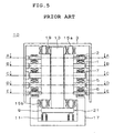
- Fig. 5 illustrates a conventional (outer rotor type) magnetic bearing device 10 in which five axes control is performed.
- Fig. 6 is a cross-sectional view taken along each of the lines A-A and E-E of Fig. 5
- Fig. 7 is a cross-sectional view taken along the line C-C of Fig. 5
- Fig. 8 is a cross-sectional view taken along each of the lines B-B and D-D of Fig. 5.
- an upper radial electromagnet 1 is capable of adjusting the position in the radial direction (hereinafter referred to simply as "radial position") of an upper portion of an outer rotor 3 with an adjustment meter or the like (not shown in the figures) based on a radial position in an X-axis direction and a Y-axis direction detected by an upper radial position detection sensor 2.
- a lower radial electromagnet 5 is capable of adjusting the radial position of a lower portion of the outer rotor 3 with an adjustment meter or the like (not shown) based on a radial position in an X-axis direction and a Y-axis direction detected by a lower radial position detection sensor 6.
- a motor 7 is provided between the upper radial electromagnet 1 and the lower radial electromagnet 5 to rotate the outer rotor 3 at a high speed.
- a shaft 13 is provided at the center of the outer rotor 3. The shaft 13 penetrates a hole 19 formed in a central portion of a stator 17.
- a disk 9 is fixed to the lower end of the shaft 13 and is accommodated in a disk chamber 21 formed in a bottom portion of the stator 17.
- axial position The position in the axial direction (hereinafter referred to simply as "axial position") of the disk 9 is detected by an axial position sensor 11 mounted in a bottom section of the disk chamber 21.
- the axial position of the outer rotor 3 is adjusted through an adjustment meter or the like (not shown) by balancing attractions of axial electromagnets 15a and 15b.
- the axial electromagnet 15a attracts the outer rotor 3 downward, while the axial electromagnet 15b attracts the disk 9 upward.
- the axial electromagnet 15a is provided on the upper end of the stator 17, and the axial electromagnet 15b is provided in an upper section of the disk chamber 21.
- the conventional magnetic bearing device 10 has only a magnetic bearing as a bearing for the operation in the normal state and, therefore, has a problem described below.
- a transfer function G(s) defined by the following equation 1 for the relationship between the position P(t) of the outer rotor 3 and force F(t) for moving the outer rotor 3 to a target position (hereinafter referred to as "control force") has a frequency characteristic such that the gain decreases in a particular frequency range, such as a range about a resonance point.
- G(s) F(s)/P(s) (where s is a Laplacian operator)
- the present invention has been made in view of the above-described problem of the conventional art, and an object of the present invention is therefore to provide a magnetic bearing device capable of obtaining a sufficient force to control a rotating member through the entire frequency range, capable of preventing touchdown, smaller in size, and having lower power consumption.
- a magnetic bearing device comprising: a rotating member; magnetic bearing means for supporting the rotating member by magnetic force, and for adjusting the radial position and/or the axial position of the rotating member; a stator on which the magnetic bearing means is fixed; and dynamic fluid pressure generation means for reinforcing the control force of the magnetic bearing in a compensating manner by dynamic fluid pressure produced in a small clearance formed between the stator and the rotating member as the rotating member rotates.
- the rotating member comprises an inner rotor type and an outer rotor type.
- the magnetic bearing means supports the rotating member by magnetic force, and adjusts the radial position and/or the axial position of the rotating member. That is, the magnetic bearing means may adjust only the radial position or the axial position of the rotating member or may adjust both the radial and axial positions.
- the magnetic bearing means may have any number of control axes. For example, it may be of a three axes control type or a five axes control type.
- the magnetic bearing means is fixed on the stator.
- the dynamic fluid pressure generation means has a small clearance formed between the stator and the rotating member. As the rotating member rotates, the control force of the magnetic bearing is reinforced in a compensating manner by dynamic fluid pressure produced in the clearance between the stator and the rotating member.
- the magnetic bearing means has lower stiffness about a resonance point and becomes susceptible to turbulence.
- the dynamic fluid pressure generation means is provided to compensate for such a condition by a dynamic fluid pressure produced in the clearance between the stator and the rotating member. Therefore, the rotating member can rotate with improved stiffness through the entire frequency range.
- the magnetic bearing means is provided to enable the rotating member to be supported always stably in a non-contact manner by being floated by magnetic force, thereby preventing touchdown at the time of starting, stopping, etc.
- the magnetic bearing means and the dynamic air pressure generation means mutually offset their shortcomings to enable stable control of the rotating member.
- the magnetic bearing device is characterized in that the rotating member has an outer rotor and a shaft provided at the center of the outer rotor, and in that the stator has a hole formed therein, the shaft being passed through the hole with a small clearance formed between the stator and the shaft in the hole, and the dynamic fluid pressure generation means has grooves for generating dynamic air pressure, the grooves being formed partially or entirely in the inner surface of the stator defining the hole and facing the shaft and/or in the cylindrical surface of the shaft.
- the rotating member is of an outer rotor type.
- the shaft is provided at the center of the outer rotor. Through the hole formed in the stator, the shaft is passed with a small clearance. Grooves for generating dynamic air pressure are formed partially or entirely in the inner surface of the stator defining the hole and facing the shaft, and/or in the cylindrical surface of the shaft.
- the force of the magnetic bearing means for adjustment in the radial direction can be reinforced in a compensating manner by dynamic air pressure produced in the gap between the stator and the shaft.
- the magnetic bearing device is characterized in that the rotating member has an outer rotor, a shaft provided at the center of the outer rotor, and a disk provided on a lower portion of the shaft, and in that disk bottom surface facing means is provided in a bottom portion of the stator by being slightly spaced apart form the disk so as to face a bottom surface of the disk with a predetermined clearance formed therebetween, and the dynamic fluid pressure generation means has grooves for generating dynamic air pressure, the grooves being formed partially or entirely in an upper surface of the disk bottom surface facing means and/or in the bottom surface of the disk.
- the rotating member is of an outer rotor type.
- the shaft is provided at the center of the outer rotor, and the disk is provided on a lower portion of the shaft.
- the disk bottom surface facing means is provided in a bottom portion of the stator by being slightly spaced apart form the disk so as to face the bottom surface of the disk with a predetermined clearance formed therebetween. Grooves for generating dynamic air pressure are formed partially or entirely in the upper surface of the disk bottom surface facing means and/or in the bottom surface of the disk.
- the force of the magnetic bearing means for adjustment in the axial direction can be reinforced in a compensating manner by dynamic air pressure produced in the clearance between the upper surface of the disk bottom surface facing means and the bottom surface of the disk.
- FIGS. 1 through 4 show an embodiment of the present invention which is a magnetic bearing device 20 (of an outer rotor type) in which five axes control is performed. Components of this embodiment identical or corresponding to those shown in Figs. 5 through 8 are indicated by the same reference characters, and the description for them will not be repeated.
- a small clearance of several ⁇ m is provided between a shaft 13 and an inner surface of a stator 17 defining a hole 19.
- grooves 23 having a depth of several ⁇ m are spirally formed to constitute a dynamic pressure bearing.
- Dynamic pressure bearing grooves 23 may be formed through the entire inner surface of the hole 19 of the stator 17 along the shaft. Alternatively, grooves 23 may be formed, for example, only in portions of the inner surface of the hole 19 at axial positions corresponding to an upper radial electromagnet 1 and a lower radial electromagnet 5.
- a small clearance of several ⁇ m is provided between the upper surface of the projecting portion 25 and the bottom surface of a disk 9.
- Grooves 27 having a depth of several ⁇ m are formed in the upper surface of the projecting portion 25 so as to extend spirally from a central point thereof.
- the shaft 13 can be supported with high stiffness in the radial direction.
- the outer rotor 3 rotates, it is supported in a non-contact manner with stability and high stiffness through the entire frequency range. Also, whirl of the outer rotor 3 is not increased, and the size of the electromagnets of the magnetic bearing can be reduced. Thus, the size and power consumption of the magnetic bearing device 20 can be reduced.
- the outer rotor 3 falls or does not float suitably when, for example, the outer rotor 3 stops or starts rotating, thereby causing contact between the shaft 3 and the inner surface of the hole 19 of the stator 17, etc.
- the inner surface of the hole 19 may be scratched or scuffed and the grooves 23 and 27 may be damaged, resulting in deterioration of the slide bearing performance and failure to perform stable control of the outer rotor 3.
- the magnetic bearing and the dynamic air pressure bearing are combined to enable the outer rotor 3 to be supported always stably in a non-contact manner by being floated by magnetic force even when it is in a stationary state, thus preventing touchdown at the time of starting, stopping, etc. The possibility of damage is thereby reduced.
- the magnetic bearing and the dynamic air pressure bearing mutually offset their shortcomings to enable stable control of the outer rotor 3.
- the bearing device is arranged so that dynamic air pressure works.
- the same arrangement is available in combination with dynamic pressure of any other fluid.
- the number of control axes of the magnetic bearing is not particularly limited. Further, even in the case where the rotating member is of an inner rotor type, slide bearings may be discontinuously arranged in the axial direction out of the places for magnetic bearing portions to achieve the same effect.
- magnetic bearing means and dynamic fluid pressure generation means are provided, and the magnetic bearing means and dynamic fluid pressure generation means mutually offset their shortcomings to enable stable control of the rotating member. Therefore, the size of the electromagnets of the magnetic bearing can be reduced and the overall size and power consumption of the magnetic bearing device can be reduced.
Landscapes
- Engineering & Computer Science (AREA)
- General Engineering & Computer Science (AREA)
- Mechanical Engineering (AREA)
- Physics & Mathematics (AREA)
- Fluid Mechanics (AREA)
- Chemical & Material Sciences (AREA)
- Oil, Petroleum & Natural Gas (AREA)
- Magnetic Bearings And Hydrostatic Bearings (AREA)
- Sliding-Contact Bearings (AREA)
- Connection Of Motors, Electrical Generators, Mechanical Devices, And The Like (AREA)
Abstract
Description
Claims (3)
- A magnetic bearing device comprising:a rotating member;magnetic bearing means for supporting the rotating member by magnetic force, and for adjusting a radial position and/or an axial position of the rotating member;a stator on which the magnetic bearing means is fixed; anddynamic fluid pressure generation means for reinforcing the control force of the magnetic bearing in a compensating manner by dynamic fluid pressure produced in a small clearance formed between the stator and the rotating member as the rotating member rotates.
- A magnetic bearing device according to claim 1, wherein the rotating member has an outer rotor and a shaft provided at a center of the outer rotor, and whereinthe stator has a hole formed therein, the shaft being passed through the hole with a small clearance formed between the stator and the shaft in the hole, and the dynamic fluid pressure generation means has grooves for generating dynamic air pressure, the grooves being formed partially or entirely in an inner surface of the stator defining the hole and facing the shaft and/or in a cylindrical surface of the shaft.
- A magnetic bearing device according to claim 1 or 2, wherein the rotating member has an outer rotor, a shaft provided at a center of the outer rotor, and a disk provided on a lower portion of the shaft, and whereindisk bottom surface facing means is provided in a bottom portion of the stator by being slightly spaced apart form the disk so as to face a bottom surface of the disk with a predetermined clearance formed therebetween, and the dynamic fluid pressure generation means has grooves for generating dynamic air pressure, the grooves being formed partially or entirely in an upper surface of the disk bottom surface facing means and/or in the bottom surface of the disk.
Applications Claiming Priority (2)
| Application Number | Priority Date | Filing Date | Title |
|---|---|---|---|
| JP21096799 | 1999-07-26 | ||
| JP11210967A JP2001041235A (en) | 1999-07-26 | 1999-07-26 | Magnetic bearing device |
Publications (2)
| Publication Number | Publication Date |
|---|---|
| EP1072804A2 true EP1072804A2 (en) | 2001-01-31 |
| EP1072804A3 EP1072804A3 (en) | 2002-08-07 |
Family
ID=16598097
Family Applications (1)
| Application Number | Title | Priority Date | Filing Date |
|---|---|---|---|
| EP00306103A Withdrawn EP1072804A3 (en) | 1999-07-26 | 2000-07-18 | Magnetic bearing device |
Country Status (2)
| Country | Link |
|---|---|
| EP (1) | EP1072804A3 (en) |
| JP (1) | JP2001041235A (en) |
Cited By (1)
| Publication number | Priority date | Publication date | Assignee | Title |
|---|---|---|---|---|
| WO2016150706A1 (en) * | 2015-03-24 | 2016-09-29 | Krones Ag | Apparatus for use in the beverage industry, comprising a radial bearing and/or a thrust bearing |
Family Cites Families (3)
| Publication number | Priority date | Publication date | Assignee | Title |
|---|---|---|---|---|
| EP0528274B1 (en) * | 1991-08-19 | 1997-03-05 | Sumitomo Electric Industries, Limited | Composite bearing structure |
| JP2000314421A (en) * | 1999-04-30 | 2000-11-14 | Sumitomo Electric Ind Ltd | Radial / axial composite bearing structure and spindle motor having the same structure |
| JP2003222124A (en) * | 1999-07-14 | 2003-08-08 | Sumitomo Electric Ind Ltd | Spindle motor |
-
1999
- 1999-07-26 JP JP11210967A patent/JP2001041235A/en active Pending
-
2000
- 2000-07-18 EP EP00306103A patent/EP1072804A3/en not_active Withdrawn
Cited By (1)
| Publication number | Priority date | Publication date | Assignee | Title |
|---|---|---|---|---|
| WO2016150706A1 (en) * | 2015-03-24 | 2016-09-29 | Krones Ag | Apparatus for use in the beverage industry, comprising a radial bearing and/or a thrust bearing |
Also Published As
| Publication number | Publication date |
|---|---|
| EP1072804A3 (en) | 2002-08-07 |
| JP2001041235A (en) | 2001-02-13 |
Similar Documents
| Publication | Publication Date | Title |
|---|---|---|
| US5273368A (en) | Hydrodynamic gas bearing | |
| KR101588357B1 (en) | Rotor assembly | |
| EP1350035B1 (en) | Compliant foil fluid film bearing with eddy current damper | |
| US7066652B2 (en) | Externally pressurized gas bearing and spindle equipment using this | |
| JPH09163677A (en) | Spindle motor | |
| US20040126040A1 (en) | Fluid dynamic bearing module | |
| JP3733160B2 (en) | Magnetic bearing device | |
| US7465097B2 (en) | Fluid dynamic bearing system | |
| JP3240637B2 (en) | Bearing device | |
| JP2850342B2 (en) | Bearing device | |
| JP2564543Y2 (en) | Turbo molecular pump | |
| JPH10292818A (en) | High-speed rotating machine | |
| Coleman | High capacity aerodynamic air bearing (HCAB) for laser scanning applications | |
| JP2000081028A (en) | Dynamic pressure bearing device for fan motor | |
| JPS6318794Y2 (en) | ||
| JP2001041235A (en) | Magnetic bearing device | |
| JPH04258525A (en) | light deflection device | |
| EP1072805A2 (en) | Magnetic bearing device | |
| JP2941864B2 (en) | Hydrostatic gas bearing and method of correcting balance of rotating body using it | |
| JPH1031187A (en) | Polygon scanner and method of manufacturing the same | |
| JPH04224313A (en) | magnetic bearing device | |
| JPS58152951A (en) | Casing support device | |
| JPH1031188A (en) | Polygon scanner | |
| JP2003074542A (en) | Shaft support method for spindle motor | |
| JP2000350402A (en) | Small motor for information equipment |
Legal Events
| Date | Code | Title | Description |
|---|---|---|---|
| PUAI | Public reference made under article 153(3) epc to a published international application that has entered the european phase |
Free format text: ORIGINAL CODE: 0009012 |
|
| AK | Designated contracting states |
Kind code of ref document: A2 Designated state(s): AT BE CH CY DE DK ES FI FR GB GR IE IT LI LU MC NL PT SE |
|
| AX | Request for extension of the european patent |
Free format text: AL;LT;LV;MK;RO;SI |
|
| PUAL | Search report despatched |
Free format text: ORIGINAL CODE: 0009013 |
|
| AK | Designated contracting states |
Kind code of ref document: A3 Designated state(s): AT BE CH CY DE DK ES FI FR GB GR IE IT LI LU MC NL PT SE |
|
| AX | Request for extension of the european patent |
Free format text: AL;LT;LV;MK;RO;SI |
|
| RIC1 | Information provided on ipc code assigned before grant |
Free format text: 7F 16C 32/04 A, 7F 16C 39/04 B, 7F 16C 33/10 B |
|
| 17P | Request for examination filed |
Effective date: 20030107 |
|
| AKX | Designation fees paid |
Designated state(s): DE FR GB |
|
| RAP1 | Party data changed (applicant data changed or rights of an application transferred) |
Owner name: SEIKO INSTRUMENTS INC. |
|
| 17Q | First examination report despatched |
Effective date: 20040325 |
|
| STAA | Information on the status of an ep patent application or granted ep patent |
Free format text: STATUS: THE APPLICATION IS DEEMED TO BE WITHDRAWN |
|
| 18D | Application deemed to be withdrawn |
Effective date: 20040805 |