EP1072779A2 - Fuel injector and internal combustion engine - Google Patents
Fuel injector and internal combustion engine Download PDFInfo
- Publication number
- EP1072779A2 EP1072779A2 EP00115078A EP00115078A EP1072779A2 EP 1072779 A2 EP1072779 A2 EP 1072779A2 EP 00115078 A EP00115078 A EP 00115078A EP 00115078 A EP00115078 A EP 00115078A EP 1072779 A2 EP1072779 A2 EP 1072779A2
- Authority
- EP
- European Patent Office
- Prior art keywords
- current
- coil
- resistance
- current application
- time
- Prior art date
- Legal status (The legal status is an assumption and is not a legal conclusion. Google has not performed a legal analysis and makes no representation as to the accuracy of the status listed.)
- Granted
Links
- 239000000446 fuel Substances 0.000 title claims description 195
- 238000002485 combustion reaction Methods 0.000 title claims description 19
- 238000002347 injection Methods 0.000 claims abstract description 135
- 239000007924 injection Substances 0.000 claims abstract description 135
- 230000008859 change Effects 0.000 claims description 16
- 230000003111 delayed effect Effects 0.000 claims description 10
- 230000004044 response Effects 0.000 abstract description 16
- 238000000034 method Methods 0.000 description 31
- 238000010586 diagram Methods 0.000 description 29
- 230000002035 prolonged effect Effects 0.000 description 9
- 238000004088 simulation Methods 0.000 description 8
- 230000003247 decreasing effect Effects 0.000 description 6
- 229920006395 saturated elastomer Polymers 0.000 description 5
- 238000007796 conventional method Methods 0.000 description 4
- 239000002828 fuel tank Substances 0.000 description 4
- 230000020169 heat generation Effects 0.000 description 4
- 230000008569 process Effects 0.000 description 4
- 230000007423 decrease Effects 0.000 description 3
- 238000012360 testing method Methods 0.000 description 3
- 230000001934 delay Effects 0.000 description 2
- 238000001514 detection method Methods 0.000 description 2
- 230000004907 flux Effects 0.000 description 2
- 238000012545 processing Methods 0.000 description 2
- 230000000630 rising effect Effects 0.000 description 2
- 238000012546 transfer Methods 0.000 description 2
- 238000004891 communication Methods 0.000 description 1
- 238000013016 damping Methods 0.000 description 1
- 230000006866 deterioration Effects 0.000 description 1
- 238000006073 displacement reaction Methods 0.000 description 1
- 230000000694 effects Effects 0.000 description 1
- 238000002474 experimental method Methods 0.000 description 1
- 239000003502 gasoline Substances 0.000 description 1
- 230000006872 improvement Effects 0.000 description 1
- 230000007246 mechanism Effects 0.000 description 1
- 238000005457 optimization Methods 0.000 description 1
- 230000009467 reduction Effects 0.000 description 1
- 230000002441 reversible effect Effects 0.000 description 1
Images


Classifications
-
- F—MECHANICAL ENGINEERING; LIGHTING; HEATING; WEAPONS; BLASTING
- F02—COMBUSTION ENGINES; HOT-GAS OR COMBUSTION-PRODUCT ENGINE PLANTS
- F02D—CONTROLLING COMBUSTION ENGINES
- F02D41/00—Electrical control of supply of combustible mixture or its constituents
- F02D41/20—Output circuits, e.g. for controlling currents in command coils
- F02D2041/202—Output circuits, e.g. for controlling currents in command coils characterised by the control of the circuit
- F02D2041/2058—Output circuits, e.g. for controlling currents in command coils characterised by the control of the circuit using information of the actual current value
-
- F—MECHANICAL ENGINEERING; LIGHTING; HEATING; WEAPONS; BLASTING
- F02—COMBUSTION ENGINES; HOT-GAS OR COMBUSTION-PRODUCT ENGINE PLANTS
- F02D—CONTROLLING COMBUSTION ENGINES
- F02D2200/00—Input parameters for engine control
- F02D2200/50—Input parameters for engine control said parameters being related to the vehicle or its components
- F02D2200/503—Battery correction, i.e. corrections as a function of the state of the battery, its output or its type
Definitions
- the present invention relates to an electromagnetic fuel injector and an internal combustion engine, and particularly to an electromagnetic fuel injector directly driven by a battery voltage and an internal combustion engine equipped with said fuel injector.
- the electromagnetic fuel injector is known as an internal combustion engine, for example, a fuel injector mounted on the vehicle such as car.
- the electromagnetic fuel injection valve (hereafter called “injector”) of this electromagnetic fuel injector comprises a nozzle provided with fuel injection hole, a plunger which is inserted in the nozzle in freely reciprocating mode with a valve on the tip thereof, and a return spring to give elastic force to the plunger in the direction of closing valve, and a coil to provide the plunger with electromagnetic force for opening the valve, using the power supplied from the battery.
- injector When current is applied to the coil, the plunger is attracted and the valve is released from the valve seat of the fuel injection hole; then fuel is jetted out of the fuel injection hole.
- application of current to the coil is suspended, magnetic attraction by the coil is damped, and the valve is closed by the elastic force of the return spring.
- the volume of injection by the injector is controlled by the valve opening command time.
- valve opening command time Generally, there is a delay of valve response with respect to valve opening command time and valve closing command time.
- An area where perfect linearity cannot be established occurs in the fuel injection volume characteristics showing the relationship between the valve opening command time and injection volume. This requires the injector to have linearity established over an extensive field.
- the injector mounted on the internal combustion engine designed for reduced costs is required to ensure accurate injection with less fuel, and linearity with respect to short valve opening command time is very important. To meet these requirements, a great variety of injector driving methods have been proposed.
- saturated method voltage drive
- peak hold method current drive
- the saturated method many turns of coil are used, and drive current continues to increase even after the valve has terminated lifting, until it reaches the point close to the saturated current which is restricted by coil internal resistance and drive circuit internal resistance.
- the circuit impedance is higher than that in the peak hold method, and the rising edge of the current flowing to the coil less sharp due to inductance. If the saturated current value is properly set by adjusting the coil internal resistance and drive circuit internal resistance, there is no need of providing a current control circuit, thereby allowing configuration at reduced costs.
- the peak hold method a smaller number of coil turns are used.
- the circuit inductance and circuit impedance are low, and the rising edge of the current in valve opening operation is sharper than that in the saturated method.
- coil inductance and impedance are low in this method. So if current is continuously applied to the coil in a specified state, excessive current will flow to the coil to damage it. To prevent this, this method uses a current limiting mechanism provided in the drive circuit. When the current flowing to the coil has reached the preset value (set peak current), the duty of voltage applied to the coil is by dropped from 100%, thereby restricting the current to the value required to hold the valve.
- the Japanese Patent Laid-Open NO. 241137/1994 discloses an electromagnetic fuel injector where the fuel pressure is detected to increase the target peak current value according to fuel pressure or to prolong the current switching time, thereby adjusting the magnetic attraction, namely, drive force with respect to the changes of the load applied to the valve body.
- the fuel injector disclosed in the Japanese Patent Laid-Open NO.241137/1994 is not directly driven by battery voltage. It has a voltage boost circuit and low voltage circuit, without consideration given to changes in electric circuit system for drive.
- the electromagnetic fuel injector driven directly by battery voltage requires consideration to be given not only to the changes of loads applied to the valve body, but also to the changes occurring to the electric circuit comprising the battery, coil and harness, such as the drop of battery voltage due to startup or abrupt change of electric load, to the secular change of the resistance of the harness including the coil, and to the increase of resistance due to heat generation.
- the injector when the peak hold method is used, the injector is not directly driven by battery voltage in the prior art; therefore, the configuration thereof is not made optimum to get the linearity of injection volume under each condition, with respect to the changes occurring to the electric circuit comprising a battery, coil and harness.
- An object of the present invention is to provide a fuel injector and internal combustion engine capable of maintaining the linearity of injection volume with respect to the changes in the state of the electric circuit to drive the electromagnetic fuel injection valve.
- a fuel injector which comprising a current application controller which controls drive of the valve body installed on an electromagnetic fuel injection valve, by controlling current so that current flows to a coil to generate magnetic force for driving said valve body until the current of driving said valve body in the direction of opening the valve becomes greater than that of holding said valve body open, and by controlling current so that a change occurs to current application time when driving said valve body in the direction of opening; wherein said current application controller allows current to be applied to reduce the maximum current in the event of increase of said current application time in current application when driving said valve body in the direction of opening said valve.
- the fuel injector comprises (1) a voltage detecting means to detect the voltage of the battery connected to said current application circuit, (2) a current detecting means to detect the current flowing to the coil connected to said current application circuit, and (3) a current value storage means to store the target peak current value in conformity to battery voltage.
- the current application controller captures the target peak current value in conformity to the voltage detected by said voltage detecting means from said current detecting means, compares between said target peak current value and the current detected by said current detecting means, and controls current application using as a target value the current value which is smaller than said target peak current value, on conditions of agreement of said two current values.
- the current storage means is preferred to store the target peak current where the current is reduced in conformity to the drop of the voltage of the battery connected to the electric circuit.
- said injector comprises (1) a combined resistance estimating means to estimate the combined resistance including the resistance of said current application circuit to connect the battery with coil, and the resistance of the coil connected to said current application circuit, (2) a current detecting means to detect current flowing to said current application circuit, and (3) a current storage means to store the target peak current in conformity to said combined resistance; wherein said current application controller captures from said current storage means the target peak current in conformity to the resistance estimated by said combined resistance estimating means, compares this target peak current with the current detected by the current detecting means, and controls current application using as a target value the current value which is smaller than said target peak current value, on conditions of agreement of said two current values.
- the combined resistance estimating means is preferred to be configured to ensure that estimate changes in the composed resistance including the resistance of said current application circuit and the resistance of the coil connected to said current application circuit, from the relationship between the current value stored in said storage means and combined resistance, using the time elapsed after start of current application and the current value after lapse of a specified time.
- a voltage detecting means be provided, and the storage means to store the relationship between the current and combined resistance store the relationship between the current and combined resistance with respect to voltages of multiple batteries, and configuration be designed to estimate the combined resistance including the resistance of said current application circuit and the resistance of the coil connected to said current application circuit, based on the battery voltage detected by the voltage detecting means.
- the current value storage means stores a target peak current value where current value is reduced in conformity to increase of the combined resistance.
- a fuel injector comprises (1) a voltage detecting means to detect the voltage of the battery connected to said current application circuit, (2) a current detecting means to detect the current flowing to the coil connected to said current application circuit, and (3) a timing storage means to store the time to switch in conformity to said battery voltage; wherein said current application controller measure the time elapsed from the start of current application in the case of driving the valve body in the direction of opening the valve, captures from said timing storage means the time to switch in conformity to the voltage detected by said voltage detecting means, compares this switching time with said measured time, and controls current application using as a target value the current value which is smaller the current flowing to said coil, on conditions of agreement of said two times.
- the timing storage means store the target switching time which is delayed in conformity to the drop of battery voltage.
- the fuel injector comprises (1) a combined resistance estimating means to estimate the combined resistance including the resistance of said current application circuit to connect the battery to the coil, and the resistance of the coil connected to said current application circuit, (2) a current detecting means to detect current flowing to the coil, and (3) a timing storage means to store the time to switch in conformity to said combined resistance; wherein the current application controller measure the time elapsed from the start of current application in the case of driving the valve body in the direction of opening the valve, captures from said timing storage means the time to switch in conformity to the resistance estimated by said combined resistance estimating means, compares this switching time with said measured time, and controls current application using as a target value the current value which is smaller the current flowing to said coil, on conditions of agreement of said two times.
- control it is preferred to provide control to delay the time to switch the state of current application from the target peak current value to the holding current value, if there is an increase of the combined resistance including the resistance of the current application circuit and the resistance of the coil connected to this current application circuit.
- timing storage means store the target switching time which is delayed in conformity to the increase of the combined resistance.
- a fuel injector which comprising a current application controller which controls drive of the valve body installed on an electromagnetic fuel injection valve, by controlling current so that current flows to a coil to generate magnetic force for driving said valve body until the current of driving said valve body in the direction of opening the valve becomes greater than that of holding said valve body open, and by controlling current so that a change occurs to current application time when driving said valve body in the direction of opening; wherein said current application controller controls current to the coil, based on fuel injection command pulse with the width thereof compensated when there is an increase in current application time.
- the above object can also be attained by the invention providing a fuel injector which comprising a current application controller which controls drive of the valve body installed on an electromagnetic fuel injection valve, by controlling current so that current flows to a coil to generate magnetic force for driving said valve body until the current of driving said valve body in the direction of opening the valve becomes greater than that of holding said valve body open, and by controlling current so that a change occurs to current application time when driving said valve body in the direction of opening;
- said fuel injector comprises a combined resistance estimating means to estimate the combined resistance including the resistance of said current application circuit to connect between the battery electrically connected to said coil to supply current thereto and said coil, and the resistance of said coil; and said current application controller controls current to the coil, based on fuel injection command pulse with the width thereof compensated in conformity to the resistance estimated by said combined resistance estimating means.
- delay in valve closing operation is reduced by allowing current to be applied to reduce the maximum current in the event of increase of said current application time when driving said valve body in the direction of opening said valve, thereby maintaining linearity of injection volume.
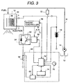
- an internal combustion engine for example, an electromagnetic fuel injector mounted on the vehicle such as car, has an injector 10.
- Fuel in fuel tank 12 is supplied to this injector 10 through a fuel passage 16 by the drive of a fuel tank 14, and D.C. power is supplied thereto from a battery 18.
- a battery 18 When current is applied to a coil 20 built in the injector 10, the fuel of the fuel passage 16 is injected to the engine (not illustrated).
- the voltage of battery 18 is applied to the coil 20 without being boosted by the booster circuit, etc. Therefore, when the resistance of the current application circuit is taken into account, voltage below the battery voltage is applied to the coil 20.
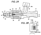
- injector 10 comprises a cylindrical injector proper 22 connected to fuel passage 16, a cylindrical guide 24 inserted into the internal surface of the cylindrical injector proper 22, a bobbin 26 secured on the external surface of the guide 24, a coil 20 mounted on the bobbin 26, a cylindrical core 28 surrounding the external surface of the coil 20, a yoke 30 formed on the tip of the core 28 integrally therewith, a cylindrical nozzle 32 secured on the internal surface of the yoke 30, a freely reciprocating plunger 34 inserted into the nozzle 32, and a return spring 36 laid out adjacent to the plunger 34, as shown in Fig. 2 (a).
- Said coil 20 is connected to said battery 18 through a terminal 38 and connector 38a.
- a fuel injection hole 40 is formed on the tip of the nozzle 32, and the tip of the nozzle 32 is opened or closed by the conical valve (valve body) 42.
- This valve 42 is formed on the tip of the plunger 34 integrally therewith.
- Receiving elastic force from the return spring 36 as an elastic body, valve 42 closes seat surface (valve seat) 44.
- a swirler 46 to atomize the fuel is provided halfway the tip of the plunger 34.
- Voltage from battery 18 is applied to the coil 20. When the coil 20 is energized, magnetic flux is generated from the coil 20.
- a magnetic path connecting the yoke 30, core 28 and plunger 34 is formed to generate magnetic attraction (electromagnetic force) among the core 28, yoke 30, and plunger 34.
- valve 42 Force to open the valve is given to valve 42 by this magnetic attraction against elastic force of closing the valve. Then the valve 42 is released from the seat surface 44, and fuel is jetted through the fuel injection hole 40.
- the coil 20 and core 28 can be represented by the equivalent circuit model shown in Fig. 2 (b).
- the load set by the return spring 36 and fuel pressure by pressurized fuel (fuel pressure) are applied to the valve when the valve is opened.
- This requires greater magnetic attraction than when the valve is held open. Only when this magnetic attraction has reached the level greater than the force including the set load and fuel pressure force, the plunger 34 starts displacement. Therefore, the time required to allow magnetic attraction to be generated from the coil 20 must be minimized since it affects delay in opening the valve 42. In other words, this requires a quick application of current to the coil 20.
- peak hold method is used for the injector 10 in the present embodiment, and both the resistance and inductance of the coil 20 are set to a small value.
- the valve 42 can be held open with a smaller magnetomotive force when the valve 42 is held open than when the valve 42 is opened. This is because fuel is jetted from the fuel injection hole 40 by the opening of valve 42, pressure is balanced before and after the valve 42, and the force by fuel pressure is reduced. At the same time, air gap with core 28, yoke 30 and plunger 34 is reduced to cause the magnetic flux density of this air gap to be increased. This makes it possible to make an effective use of the magnetomotive force. Furthermore, when closing the valve 42 after opening it, the magnetomotive force in holding the valve is reduced by suspending application of voltage to the coil 20. If the magnetomotive force is reduced below the set load of the return spring 36, then the valve starts to close.
- the present embodiment adopts the following configuration: Current detecting resistor 52 is connected to one end of the coil 20 through power transistor 50, as shown in Fig. 1. At the same time, one end of the current detecting resistor 52 is connected to the ground, and diode 54 is connected to both ends of power transistor 50 in anti-parallel mode.
- the power transistor 50 as a switching element, is inserted in the current application circuit connecting between battery 18 and coil 20 together with the current detecting resistor 52.
- Current control circuit 56 is connected to the base of the power transistor 50, and the current control circuit 56 is connected with engine controller 58 and current switching control unit 60.
- the engine controller 58 is configured to output to the current controller 56 the injection command pulse (pulse width Ti) determined according to the engine operation state such as throttle opening.
- the current control circuit 56 turns on the power transistor 50 in response to the injection command pulse, and starts current to be applied to the coil 20.
- configuration is designed to repeat on-off operations of power transistor 50 in order to allow holding current smaller than the target peak current to flow to the coil 20 in response to switching command from the current switching control unit 60.
- the current switching control unit 60 comprises a comparator 62, switching current determining unit 64, resistance estimation unit 66, target peak current storage unit 68 and timer 70.
- Comparator 62 is connected to current detecting resistor 52 and current control circuit 56.
- the switching current determining unit 64 is connected to the engine controller 58, fuel pressure sensor 72 and battery 18.
- the target peak current storage unit 68 as a current storage means stores the data on the target peak current in conformity to battery voltage, fuel pressure and harness resistance.
- the switching current determining unit 64 captures the output voltage of battery 18 and has a function as a voltage detecting means to detect battery 18. At the same time, it captures clock signals from timer 70 and has a function as a measuring means to measure the time elapsed after start of current application according to these clock signals. Furthermore, the switching current determining unit 64 captures the detection pressure of fuel pressure sensor 72 as a fuel pressure detecting means to detect fuel pressure in the fuel passage 16. At the same time, it captures the resistance estimated from the resistance estimating unit 66, namely, the combined resistance including the resistance of the current application circuit connecting the battery 18 with coil 20 and resistance of coil 20; it captures said resistance as harness resistance.
- the target peak current storage unit 68 It captures from the target peak current storage unit 68 the target peak current value in conformity to the changes in battery voltage, fuel pressure or harness resistance, and outputs this target peak current value to the comparator 62. Furthermore, it has the function of a pulse compensating means which compensate the pulse width Ti of the injection command pulse (pulse width set on condition that the battery voltage is within the scope of the rated voltage, the combined resistance denotes the set value, and the fuel pressure inside the fuel passage indicates the set value) according to the changes in voltage of the battery voltage 18, changes of harness resistance or changes of fuel pressure.
- the comparator 62 compares between the output of the current detecting resistor 52 as a current detecting means to detect the current flowing to the coil 20, and the target peak current value selected by the switching current determining unit 64. When the current flowing to coil 20 has agreed with the target peak current value, switching command is output to the current control circuit 56.
- the power transistor 50, diode 54, current control circuit 56 and current switching control unit 60 are configured to serve as communication control
- a switching command to specify the current to be switched is issued from the current switching control unit 60 to the current control circuit 56.
- a target switching time storage unit (timing storage means) 74 is provided instead of target peak current storage unit 68, and a switching timing determining unit 76 is installed instead of the switching current determining unit 64.
- the switching timing determining unit 76 measures the clock pulses coming from the timer 70 from the start of current application, and issues the switching command from the switching time storage unit 72 to the current control circuit 56, on condition that the time elapsed after the start of current application has agreed with the target switching timing.
- the target peak current storage unit 68 and target switching time storage unit (timing storage means) 74 store the data on the target peak current value and target switching timing determined by the relationship between the battery voltage and oil current in relation to the changes in the voltage of the battery 18, as shown in Fig. 4.
- Fig. 4 (a) illustrates the characteristics representing the relationship between the battery voltage and coil current when coil 20, harness resistance and fuel pressure are set at desired values.
- Fig. 4 (a) shows that response of the coil current is reduced by drop of the battery voltage.
- the curve shown by the dotted line in the Figure represents the optimum injection characteristics. This curve can be obtained either by experiment or simulation. The crossing point between this optimum curve and the current response is the optimum target peak current value at each battery voltage.
- Fig. 4 (b) tabulates the relationship of the characteristics shown in (a).
- the values which is reduced in the direction where the battery voltage is reduced are given to the table for target peak current value.
- the values which increase in the direction where the battery voltage is reduced are given as the time to reach the peak, namely, target switching timing.
- This embodiment shows an example of obtaining the target peak current value for every first drive of injector 10 (an example of obtaining the target peak current value of the i + 1-th injection from the detection result of i-th injection).
- the battery voltage Vbi prior to i-th injection is detected (step S1).
- battery voltage Vbi is applied to coil 10 (step 2).
- clock signals coming from the timer 70 are measured.
- measured time T is the same as the preset time Tc, current Ip (Vbi) flowing to coil 20 is detected (step 3).
- step 4 the data in the column of battery voltages Vbi is sought from the current response value map at time Tc with respect to each battery voltage Vb and each resistance Rc stored in the resistance estimating unit 66 (step 4). Then the resistance value Rci which becomes the current value Ipii closest to the coil current Ip (Vbi) is stored as coil and harness resistance (step 5). After that, the output from the fuel pressure sensor 72 is captured and fuel pressure Pfi of i-th injection is detected (step 6).
- the above processing allows battery voltage Vbi, resistance Rci and fuel pressure Pfi in the i-th injection to be clarified. These values are used as bases to seek the Ip map inside the resistance estimating unit 66 and to obtain the i + 1-th target peak current value Ip (i + 1) (step 7). Then the i + 1-th coil current application is carried out based on the target peak current value Ip (i + 1) (step 8).
- repeating the steps S1 to S8 allows the injector 10 to be driven always at the optimum target peak current value.
- the data on Tp map of the target switching time storage unit 74 is sought to obtain the i + 1-th target switching time (target switching timing) Tp (i + 1), instead of obtaining i + 1-th target peak current value Ip (i + 1) in step 7. Then i + 1-th coil current application is performed based on the target switching time Tp (i + 1).
- Drive of the power transistor 50 is controlled by the current control circuit 56 in conformity to the target peak current value or target switching time (target switching timing) determined by the above processing.
- target switching time target switching timing
- the power transistor 50 is kept turned on by ON-signals coming from the current control circuit 56, and battery voltage is continuously applied to coil 20 to increase the volume of current sent to the coil.
- the power transistor 50 is deactivated once.
- the power transistor 50 repeats on-off operations to get holding current lower than coil current value at that time point, thereby maintaining the current at the holding current value to be sent to coil 120.
- the holding current required to hold the valve 42 open is supplied to the coil 20.
- the following describes the drive method according to the present invention when battery voltage, resistance and fuel pressure are set to the standard state. At the same time, it also discussed the result of comparison between the drive method according to the present invention and conventional drive method when the battery voltage has dropped, when coil and harness resistance has increased, and when fuel pressure (fuel pressure) has increased.
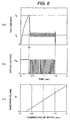
- Fig. 6 (a) is a characteristic diagram representing an example of injector 10 turned on when the width T of the injection command pulse coming from the engine controller 58 is 1.5 ms.
- the target peak current value read from the target peak current storage unit 68 is Ip.
- the power transistor 50 is kept turned on, and battery voltage Vb is continuously applied to the coil 20.
- current flowing to the coil 20 makes an abrupt increase and coil current has reached Ip under this condition, power transistor 50 is turned off by the command from comparator 62, and voltage applied to the coil 20 is suspended once. Time in this case is assumed as Tp. This makes coil current reduced below Ip. In this case, coil current is detected by the current detecting resistor 52.
- Fig. 6 (c) is a characteristic diagram for injection volume where width Ti (ms) of the injection command pulse coming from the engine controller 58 is plotted on the horizontal axis, and injection volume in this case is assigned on the vertical axis.
- the target peak current value is set to the optimum value Ip, and holding current is set to the optimum value Ih. This makes it possible to realize the characteristics that the volume of injection exhibits a linear increase in conformity to increase of the width of injection command pulse when the valve is opened.
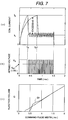
- Figs. 7(a) and (b) are characteristic diagrams showing changes in coil current and applied voltage when target current Ip is kept unchanged, even if the battery voltage is dropped with resistance and fuel pressure kept unchanged from the state of Fig. 6.
- Fig. 7 (c) is a characteristic diagram for injection volume where width Ti (ms) of the injection command pulse coming from the engine controller 58 is plotted on the horizontal axis, and injection volume with battery voltage reduced to Vb1 is assigned on the vertical axis.
- drop of the battery voltage results in later rise of coil current and delay of the valve opening time. This also delays the rise of injection volume, as shown in (c). So when the valve is opened, pressure is balanced around the valve 42, and the force applied to valve 42 is reduce, as discussed earlier.
- the current value becomes holding current Ih immediately. If the battery voltage is low, however, current application time is Tp1 or more.
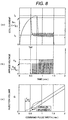
- Fig. 8 is a characteristic diagram where a low value is selected as a target peak current value in conformity to the drop of battery voltage when the battery voltage has dropped.
- the time before the coil current reaches target peak current value can be assumed as Tp2 by setting the target peak current to the value Ip1 ( ⁇ Ip) optimum to battery voltage Vb1 ( ⁇ Vb) in the event of battery voltage drop, as shown in Fig. 8. At the same time, this ensures an early transfer of coil current to current value Ih appropriate to holding the valve 42 open. Furthermore, the optimum peak current Ip1 (target peak current) for this battery voltage Vb1 may be obtained either on an experimental basis by injector characteristics test or by simulation.
- the target peak current value in opening the valve is set to the optimum value Ip1, and the holding current is set to the optimum value Ih.
- offset Ts1 is added to pulse width Ti to compensate for injection command pulse width Ti in the event of battery voltage drop. Optimization of the injection volume characteristics can be ensured by current application in response to the injection command pulse having the compensated pulse width. For example, if the width of required injection command pulse of the engine controller 58 is Ti0ms, current application time is compensated as (Ti0 ⁇ Ts1) ms. This makes it possible to keep injection volume characteristics to have the optimum linearity while the impact of battery voltage drop is minimized.
- Figs. (a) and (b) show the characteristics of the coil current and applied voltage in driving the coil 20 with the target peak current Ip kept under the same condition as Fig. 6, when the coil and harness resistance has increased, with the battery voltage and fuel pressure kept unchanged from the standard state shown in Fig. 6.
- Fig. 9 (c) is a characteristic diagram for injection volume where width Ti (ms) of the injection command pulse coming from the engine controller 58 is plotted on the horizontal axis, and injection volume with resistance increased to R1 is assigned on the vertical axis.
- width Ti (ms) of the injection command pulse coming from the engine controller 58 is plotted on the horizontal axis, and injection volume with resistance increased to R1 is assigned on the vertical axis.
- the margin for coil current rise is reduced, and the valve opening time is delayed. This delays the rise of injection volume, as shown in (c). So when the valve is opened, pressure is balanced around the valve 42, and the force applied to valve 42 is reduce, as discussed earlier.
- Injection volume is increased, with the result that a convex upward characteristic curve appears.
- abrupt rise characteristic for pulse width appears.
- This characteristic deteriorates linearity, and the minimum injection volume increases in the controllable range, with the result that application to low fuel engine will be difficult.
- coil current cannot reach the target peak current value Ip for the width of the maximum injection command pulse, and the optimum current value Ih to hold the valve 42 is not obtained.
- Current application terminates at a high current.
- heat generation or burnout may occur due to long-time current application at a modestly high current.
- Fig. 10 shows the result of characteristics when low target peak current value is selected in conformity to resistance increase when there is an increase of resistance.
- the target peak current is set to value Ip2 ( ⁇ Ip) optimum to resistance R1 when resistance has increased, as shown in Fig. 10. This makes it possible to ensure the time for coil current to reach the target peak current value is Tp3. This ensures an early transfer of the holding current required to hold the valve 42 to the current value Ih.
- the optimum peak current Ip2 (target peak current value) for this resistance R may be obtained either on an experimental basis by injector characteristics test or by simulation.
- target peak current value is set to the optimum value Ip when the valve is open. Since the holding current is set to the optimum value Ih, it is possible to realize the characteristics of the linear increase of injection volume in conformity to increase in the width of the injection command pulse when the valve is open.
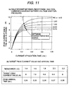
- Fig. 11 (a) shows the relationship between the coil and harness resistance and coil current response when the battery volume and fuel pressure are set at desired values. From this Fig., it is apparent that increase in the coil and harness resistance means a decrease of the current convergent value.
- a dotted line in the Fig. denotes the curve where the injection volume characteristics are made optimum. This curve can be may be obtained either on an experimental basis or by simulation. The crossing point between this optimum current and current response is the optimum target peak current value for each of the coil and harness resistances.
- Fig. 11 (b) tabulates this relationship. These data are stored in the target peak current storage unit 68 and target switching time storage unit 74. The optimum target peak current value can be uniquely determined by specifying the battery voltage and current application. This relationship is stored in the target switching time storage unit 74 as the data on target switching time.
- the data of the target peak current table shown in Fig. 11 (b) is given as a vale which decreases in the direction where resistance increases.
- the peak arrival time (target switching time) is given as a value which increases in the direction where resistance increases. In this way, injection volume characteristics can be improved by decreasing the target peak current or by delaying the target switching time when coil and harness resistance has increased, based on the data stored in the table.
- Figs. 12 (a) and (b) are characteristic diagrams showing the characteristics of the coil current and applied voltage in driving the coil 20 with the target current Ip kept in the same state as Fig. 6, when fuel pressure supplied to the injector 10 is increased to reach Pf1, with the battery voltage and resistance unchanged from the state of Fig. 6. Even when the fuel pressure has increased, the electric circuit does not change from the state in the battery voltage and coil/harness resistance, if the target current Ip is kept unchanged. So current waveform and magnetic attraction to be generated stay unchanged from the state of Fig. 6. However, the force applied to valve 42 is increased by fuel pressure, so the valve 42 is closed immediately although it opens slightly.
- Fig. 12 (c) is a characteristic diagram for injection volume where width Ti (ms) of the injection command pulse coming from the engine controller 58 is plotted on the horizontal axis, and injection volume with increased fuel pressure is assigned on the vertical axis.
- the injection volume characteristics shown in (c) denote a constant value with respect to width Ti of the injection command pulse. This shows that the valve cannot be opened despite prolonged current application time after the valve 42 has closed subsequent to opening. It is impossible to control the injection volume in terms of current application. In other words, according to the peak hold method similar to the conventional method, the valve does not open in the event of fuel pressure, and injection volume cannot be controlled current application time.
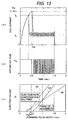
- Fig. 13 shows the characteristic results when fuel pressure is increased and target peak current value is increased in conformity to increased fuel pressure.
- the valve can be opened by changing the target peak current to the value Ip3 (>Ip) optimum to fuel pressure Pf1 in the event of increased fuel pressure, as shown in Fig. 13.
- the optimum peak current Ip3 with respect to this fuel pressure Pf1 may be obtained either on an experimental basis by injector test or by simulation.
- the target peak current value when the valve 42 is open is set to the optimum value Ip3 and the holding current is set to Ih. This makes it possible to realize the characteristics of the injection volume being linearly increased in conformity to increase in the width Ti of injection command pulse, when the valve is open.
- adoption of the above discussed drive method allows the fuel to be injected according to injection volume characteristics Q1 indicated by the solid line in Fig. 13.
- injection of fuel according to injection volume characteristics indicated by the solid line may cause a delay in opening of the valve 42 in conformity to increased fuel pressure.
- offset Ts3 is added to the pulse width Ti to correct the pulse width Ti, and current is applied to coil 20 according to the corrected injection command pulse and to compensate for the injection rate. This makes it possible to inject fuel according to the optimum injection volume characteristics as shown by characteristic Q3.
- the current application time is corrected to (Ti0 + Ts3) ms, and this corrected current application time is divided by square root ⁇ Kp of the magnification of the reference fuel pressure.
- ⁇ Kp the magnification of the reference fuel pressure
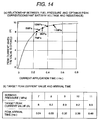
- Characteristics given in Fig. 14 are taken into account when setting the target peak current value and peak arrival time (target switching time) in conformity to increased fuel pressure.
- Fig. 14 (a) shows that the current value which optimizes injection volume characteristics in each fuel pressure is plotted on the current response where the battery voltage and coil/harness resistance are set at desired values. Each point can be may be obtained either on an experimental basis or by simulation. Each point serves as the optimum target peak current value in each fuel pressure.
- Fig. 14 (b) tabulates the relationship shown in (a). Furthermore, the optimum target peak current value can be determined uniquely by specifying the battery voltage and current application time. When this relationship is used, the data related to this table will be stored in the target switching time storage unit 74. As shown in (b), the values which increase in the direction of increasing fuel pressure are assigned as the data stored in the target peak current table. The values which increase in the direction of increasing fuel pressure are also assigned as the data on peak arrival time (target switching time).
- the injection volume characteristics can be improved by increasing the target peak current value or by delaying the target switching time when there is a increase of fuel pressure.
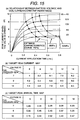
- Fig. 15 shows the map relationship of the target peak current value and target switching time with respect to the each battery voltage and fuel pressure from 7 MPa (Megapascal) to 12 MPa, where the resistance is kept constant and battery voltage changes from 6 to 14 volts.
- the optimum points of each fuel pressure in each voltage are plotted, and are connected for each fuel pressure to get the optimum curve for the injection volume characteristics in each fuel pressure. Each point may be obtained either on an experimental basis or by simulation.
- the map of Fig. 15 (b) is a two-dimensional map for the battery voltage and fuel pressure. If this map is stacked for each resistance, a three-dimensional target IP map and target Tp map are obtained.
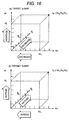
- Fig. 16 (a) is a conceptual diagram representing the target Ip map
- Fig. 16 (b) is the one showing the target Tp map.
- the target Ip map and target Tp map are 3D maps based on three augments; battery voltage, coil/harness resistance and fuel pressure.
- the data are stored in the target peak current storage unit 68 in the following directions; in the direction of decreasing target peak current for decreasing battery voltage, in the direction of decreasing target peak current for increasing resistance, and in the direction of increasing target peak current for increasing fuel pressure.
- the data are stored in the target switching time storage unit 74 in the following directions; in the direction of prolonged target switching time for decreasing battery voltage Vb, in the direction of prolonged target switching time for increasing resistance, and in the direction of prolonged target switching time for increasing fuel pressure.
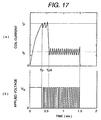
- Fig. 17 is a characteristic diagram showing the drive method where switching is performed at peak current value Ip when the valve is opened, and the peak current is held thereafter.
- the present invention can also be applied to such a drive method.
- time Tp5 to release holding of the target peak current value Ip in addition to target peak current value Ip is also stored.
- the value is switched to ensure the value optimum to the changes of battery voltage, resistance and fuel pressure. This optimum value may be obtained either on an experimental basis or by simulation.
- time Tp5 to release holding will be stored in terms of numerical values which are set in the direction of prolonged time for decreasing battery voltage, in the direction of prolonged time for increasing resistance, and in the direction of prolonged time for increasing fuel pressure.
- the above description relates to the method for searching the Ip map and Tp map when seeking the target peak current value and target switching time in conformity to battery voltage and fuel pressure in each of the above-mentioned embodiments. If map contents are highly monotonous without reverse point or singular point, the dimension of the map can be omitted, or compensation by interpolation or mathematical expression can be used.
- the above describes the case of using the single battery 18 as a battery.
- batteries with different voltages as batteries for example, 42-volt and 14-volt batteries
- the voltage of the high-voltage, battery (42 volts) is monitored by the current switching control unit 60. In the event of this voltage, target peak current value is reduced or target switching time is prolonged. Through this process, it is possible to gain similar effects as those of said embodiments.
- an engine 100 constituting the internal combustion engine comprises an igniter 102, suction unit 104, exhaust unit 106, cylinder 108 and piston 110.
- the cylinder 108 has injector 10 mounted thereon.
- a feed pump 112, pressure regulator 114 and the like together with the fuel pressure sensor 72 and fuel pump 14 are arranged on the fuel passage 16 connecting between this injector 10 and fuel tank 12.
- the cylinder 108 accommodates a freely reciprocating piston 110.
- the suction unit 104 to introduce air into the cylinder 108, exhaust unit 106 to discharge exhaust gas from the cylinder 108, injector 10 to inject fuel into the cylinder 108 and igniter 102 to ignite fuel in the cylinder 108 are laid out around this cylinder 108.
- This internal combustion engine is configured in such a way that, after being led into the fuel pump 14 by the drive of feed pump 12, the fuel in the fuel tank 12 is fed to injector 10 in a pressurized state through the fuel passage 16 by the drive of the fuel pump 14.
- the engine controller 58 determines injection timing and injection voltage in conformity to various working conditions of the engine 10 based on the information gained from various sensors (not illustrated), and sends the injection command pulse conforming to this determination to the current control circuit 56.
- the current control circuit 56 turns on the power transistor 50 in response to the injection command pulse so that current is applied to power transistor 50.
- target peak current value in conformity to battery voltage, fuel pressure and coil/harness resistance is read out of the target peak current storage unit 68. If agreement is found between the read-out target peak current and current flowing to coil 20, the current flowing to the power transistor 50 is switched over to the holding current by the switching command from the comparator 62. Then the injector 10 jets out the fuel at the optimum injection volume in conformity to various operation modes of the internal combustion engine.
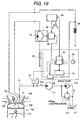
- Fig. 19 shows a block diagram showing embodiment when the electromagnetic fuel injector given in Fig. 3 is applied to the internal combustion engine.
- ON-signal is sent from the current control circuit 56 to the power transistor 50 in response to injection command pulse coming from the engine controller 58.
- the time elapsed from the start of current application is measured by the switching timing determining unit 76.
- target switching timing target switching time
- target switching time in conformity to battery voltage, fuel pressure and coil/harness resistance is read out of the target switching time storage unit 74. If agreement is found between target switching timing and time measured by the switching timing determining unit 76, the current flowing to coil 20 is switched to holding current. This allows the injector 10 to jet out fuel according to the optimum injection volume characteristics conforming to various operation modes of the internal combustion engine.
- the cylinder internal injection engine has been described according to the present embodiment.
- the electromagnetic fuel injector according to said various embodiments can also be applied to other types of engines.
- the present embodiment allows the coil to be driven in the optimum drive current waveform conforming to the changes in battery voltage, coil/harness resistance and fuel pressure. This makes it possible to get the optimum fuel injection characteristics for each mode.
- the present embodiment allows the optimum fuel injection conforming to each operation mode according to battery voltage, coil/harness resistance and fuel pressure in the internal combustion engine equipped with the electromagnetic fuel injector. This provides an internal combustion engine characterized by low fuel costs and high power.
- both target peak current value and peak arrival time for the combined resistance including the resistance of a current application circuit to connect the battery with the coil and the resistance of the coil are stored.
- the target peak current value and peak arrival time are associated with each other and are stored, and it is preferred that the state be switched over to the state of current application where the target current value is equal to the holding current, if either current value or time elapsed after start of current application has reached the target. This avoids the current being unduly increased, thereby reducing the power consumption and delay in valve closing.
- a fuel injector to drive the electromagnetic fuel injection valve by battery voltage reduction in power consumption decreases battery consumption, thereby making a significant contribution to improvement of the startup characteristics.
- the target peak current value conforming to battery voltage is selected in the event of changes in battery voltage.
- the coil current has reached the target peak current value, it is switched over to the holding current.
- target switching timing conforming to battery voltage is selected.
- the holding current smaller than the coil current value at this time is fed to the coil.
- target peak current value conforming to this combined resistance is selected.
- the coil current has reached the target peak current value
- the current is switched over to the holding current.
- target switching timing combined resistance conforming to is selected.
- the holding current smaller than the coil current value at this time is fed to the coil.
- target peak current value conforming to fuel pressure is selected.
- the current is switched over to the holding current.
- target switching timing is selected in conformity to pressure of the fuel in the fuel passage.
Abstract
Description
- The present invention relates to an electromagnetic fuel injector and an internal combustion engine, and particularly to an electromagnetic fuel injector directly driven by a battery voltage and an internal combustion engine equipped with said fuel injector.
- The electromagnetic fuel injector is known as an internal combustion engine, for example, a fuel injector mounted on the vehicle such as car.
- The electromagnetic fuel injection valve (hereafter called "injector") of this electromagnetic fuel injector comprises a nozzle provided with fuel injection hole, a plunger which is inserted in the nozzle in freely reciprocating mode with a valve on the tip thereof, and a return spring to give elastic force to the plunger in the direction of closing valve, and a coil to provide the plunger with electromagnetic force for opening the valve, using the power supplied from the battery. When current is applied to the coil, the plunger is attracted and the valve is released from the valve seat of the fuel injection hole; then fuel is jetted out of the fuel injection hole. When application of current to the coil is suspended, magnetic attraction by the coil is damped, and the valve is closed by the elastic force of the return spring.
- The volume of injection by the injector is controlled by the valve opening command time. Generally, there is a delay of valve response with respect to valve opening command time and valve closing command time. An area where perfect linearity cannot be established occurs in the fuel injection volume characteristics showing the relationship between the valve opening command time and injection volume. This requires the injector to have linearity established over an extensive field. However, the injector mounted on the internal combustion engine designed for reduced costs is required to ensure accurate injection with less fuel, and linearity with respect to short valve opening command time is very important. To meet these requirements, a great variety of injector driving methods have been proposed.
- For example, saturated method (voltage drive) and peak hold method (current drive) are well known as the injector and drive method, as disclosed in "Electronically Controlled Gasoline Injection" (by Fujisawa and Kobayashi, 1987, Sankaido Publishing Co., Ltd.).
- Generally in the saturated method, many turns of coil are used, and drive current continues to increase even after the valve has terminated lifting, until it reaches the point close to the saturated current which is restricted by coil internal resistance and drive circuit internal resistance. The circuit impedance is higher than that in the peak hold method, and the rising edge of the current flowing to the coil less sharp due to inductance. If the saturated current value is properly set by adjusting the coil internal resistance and drive circuit internal resistance, there is no need of providing a current control circuit, thereby allowing configuration at reduced costs.
- In the peak hold method, a smaller number of coil turns are used. The circuit inductance and circuit impedance are low, and the rising edge of the current in valve opening operation is sharper than that in the saturated method. However, coil inductance and impedance are low in this method. So if current is continuously applied to the coil in a specified state, excessive current will flow to the coil to damage it. To prevent this, this method uses a current limiting mechanism provided in the drive circuit. When the current flowing to the coil has reached the preset value (set peak current), the duty of voltage applied to the coil is by dropped from 100%, thereby restricting the current to the value required to hold the valve.
- Comparison of above two methods shows that the peak hold method with high current response is more frequently used in order to implement the linearity of injection volume with respect to valve opening command time in the low injection area.
- For example, the Japanese Patent Laid-Open NO. 241137/1994 discloses an electromagnetic fuel injector where the fuel pressure is detected to increase the target peak current value according to fuel pressure or to prolong the current switching time, thereby adjusting the magnetic attraction, namely, drive force with respect to the changes of the load applied to the valve body.
- The fuel injector disclosed in the Japanese Patent Laid-Open NO.241137/1994, however, is not directly driven by battery voltage. It has a voltage boost circuit and low voltage circuit, without consideration given to changes in electric circuit system for drive.
- In other words, the electromagnetic fuel injector driven directly by battery voltage requires consideration to be given not only to the changes of loads applied to the valve body, but also to the changes occurring to the electric circuit comprising the battery, coil and harness, such as the drop of battery voltage due to startup or abrupt change of electric load, to the secular change of the resistance of the harness including the coil, and to the increase of resistance due to heat generation.
- Despite battery voltage applied to the coil, drop of the battery voltage will delay the time for coil current to reach the preset peak current value. Moreover, a substantial drop of battery voltage may cause coil current to be unable to reach the preset peak current.
- In the electromagnetic fuel injector, voltage applied to the coil causes coil current to be delayed by the inductance component of the coil. Delay between the input magnetomotive force (product of current and number of coil turns) and magnetic attraction is also caused by eddy current. This delay will turn into a kind of integrating filter; therefore, not only the peak current value but also current application time must be taken into account in order to get linearity also in the low injection area with the magnetic attraction assuming an appropriate value.
- In other words, when the peak hold method is used, the injector is not directly driven by battery voltage in the prior art; therefore, the configuration thereof is not made optimum to get the linearity of injection volume under each condition, with respect to the changes occurring to the electric circuit comprising a battery, coil and harness.
- An object of the present invention is to provide a fuel injector and internal combustion engine capable of maintaining the linearity of injection volume with respect to the changes in the state of the electric circuit to drive the electromagnetic fuel injection valve.
- The above object can be attained by the invention providing a fuel injector which comprising a current application controller which controls drive of the valve body installed on an electromagnetic fuel injection valve, by controlling current so that current flows to a coil to generate magnetic force for driving said valve body until the current of driving said valve body in the direction of opening the valve becomes greater than that of holding said valve body open, and by controlling current so that a change occurs to current application time when driving said valve body in the direction of opening; wherein said current application controller allows current to be applied to reduce the maximum current in the event of increase of said current application time in current application when driving said valve body in the direction of opening said valve. In this case, it is preferred that current be applied to the coil installed on the electromagnetic fuel injection valve without boosting the battery voltage, and that a current application circuit to allow current to flow from the battery the coil be provided.
- The fuel injector comprises (1) a voltage detecting means to detect the voltage of the battery connected to said current application circuit, (2) a current detecting means to detect the current flowing to the coil connected to said current application circuit, and (3) a current value storage means to store the target peak current value in conformity to battery voltage.
- Here the current application controller captures the target peak current value in conformity to the voltage detected by said voltage detecting means
from said current detecting means, compares between said target peak current value and the current detected by said current detecting means, and controls current application using as a target value the current value which is smaller than said target peak current value, on conditions of agreement of said two current values. - In this case, the current storage means is preferred to store the target peak current where the current is reduced in conformity to the drop of the voltage of the battery connected to the electric circuit.
- Furthermore, said injector comprises (1) a combined resistance estimating means to estimate the combined resistance including the resistance of said current application circuit to connect the battery with coil, and the resistance of the coil connected to said current application circuit, (2) a current detecting means to detect current flowing to said current application circuit, and (3) a current storage means to store the target peak current in conformity to said combined resistance; wherein said current application controller captures from said current storage means the target peak current in conformity to the resistance estimated by said combined resistance estimating means, compares this target peak current with the current detected by the current detecting means, and controls current application using as a target value the current value which is smaller than said target peak current value, on conditions of agreement of said two current values.
- In this case, the combined resistance estimating means is preferred to be configured to ensure that estimate changes in the composed resistance including the resistance of said current application circuit and the resistance of the coil connected to said current application circuit, from the relationship between the current value stored in said storage means and combined resistance, using the time elapsed after start of current application and the current value after lapse of a specified time.
- It is also preferred that a voltage detecting means be provided, and the storage means to store the relationship between the current and combined resistance store the relationship between the current and combined resistance with respect to voltages of multiple batteries, and configuration be designed to estimate the combined resistance including the resistance of said current application circuit and the resistance of the coil connected to said current application circuit, based on the battery voltage detected by the voltage detecting means.
- It is further preferred to provide control to delay the time to switch the state of current application from the target peak current value to the holding current value, if there is an increase of the combined resistance including the resistance of the current application circuit and the resistance of the coil connected to this current application circuit.
- It is also preferred that the current value storage means stores a target peak current value where current value is reduced in conformity to increase of the combined resistance.
- Further, a fuel injector comprises (1) a voltage detecting means to detect the voltage of the battery connected to said current application circuit, (2) a current detecting means to detect the current flowing to the coil connected to said current application circuit, and (3) a timing storage means to store the time to switch in conformity to said battery voltage; wherein said current application controller measure the time elapsed from the start of current application in the case of driving the valve body in the direction of opening the valve, captures from said timing storage means the time to switch in conformity to the voltage detected by said voltage detecting means, compares this switching time with said measured time, and controls current application using as a target value the current value which is smaller the current flowing to said coil, on conditions of agreement of said two times.
- In this case, it is preferred that the timing storage means store the target switching time which is delayed in conformity to the drop of battery voltage.
- Further, the fuel injector comprises (1) a combined resistance estimating means to estimate the combined resistance including the resistance of said current application circuit to connect the battery to the coil, and the resistance of the coil connected to said current application circuit, (2) a current detecting means to detect current flowing to the coil, and (3) a timing storage means to store the time to switch in conformity to said combined resistance; wherein the current application controller measure the time elapsed from the start of current application in the case of driving the valve body in the direction of opening the valve, captures from said timing storage means the time to switch in conformity to the resistance estimated by said combined resistance estimating means, compares this switching time with said measured time, and controls current application using as a target value the current value which is smaller the current flowing to said coil, on conditions of agreement of said two times.
- In this case, it is preferred to provide control to delay the time to switch the state of current application from the target peak current value to the holding current value, if there is an increase of the combined resistance including the resistance of the current application circuit and the resistance of the coil connected to this current application circuit.
- It is also preferred that the timing storage means store the target switching time which is delayed in conformity to the increase of the combined resistance.
- The above object can also be attained by the invention providing a fuel injector which comprising a current application controller which controls drive of the valve body installed on an electromagnetic fuel injection valve, by controlling current so that current flows to a coil to generate magnetic force for driving said valve body until the current of driving said valve body in the direction of opening the valve becomes greater than that of holding said valve body open, and by controlling current so that a change occurs to current application time when driving said valve body in the direction of opening; wherein said current application controller controls current to the coil, based on fuel injection command pulse with the width thereof compensated when there is an increase in current application time.
- Furthermore, the above object can also be attained by the invention providing a fuel injector which comprising a current application controller which controls drive of the valve body installed on an electromagnetic fuel injection valve, by controlling current so that current flows to a coil to generate magnetic force for driving said valve body until the current of driving said valve body in the direction of opening the valve becomes greater than that of holding said valve body open, and by controlling current so that a change occurs to current application time when driving said valve body in the direction of opening;
wherein said fuel injector comprises a combined resistance estimating means to estimate the combined resistance including the resistance of said current application circuit to connect between the battery electrically connected to said coil to supply current thereto and said coil, and the resistance of said coil; and said current application controller controls current to the coil, based on fuel injection command pulse with the width thereof compensated in conformity to the resistance estimated by said combined resistance estimating means. - According to the present invention, delay in valve closing operation is reduced by allowing current to be applied to reduce the maximum current in the event of increase of said current application time when driving said valve body in the direction of opening said valve, thereby maintaining linearity of injection volume.
- By controlling current to the coil based on fuel injection command pulse with the width thereof compensated when there is an increase in current application time, it is possible to reduce the influence on fuel injection volume given by the change in the state of the drive circuit which causes the current application time to increase. This allows linearity of injection volume to be maintained.
- It is also possible to reduce the influence of combined resistance on the fuel injection volume by compensating the pulse width in conformity to the combined resistance including the resistance of the current application circuit connecting the battery with coil and the resistance of the coil. This allows linearity of injection volume to be maintained.
-
- Fig. 1 is a block diagram representing the electromagnetic fuel injection given in the first embodiment;
- Fig. 2 is a diagram representing the injector structure and equivalent circuit model;
- Fig. 3 is a block diagram representing the electromagnetic fuel injection given in the second embodiment;
- Fig. 4 is a diagram showing the relationship between the battery voltage and coil current, and the relationship between the target current and time table;
- Fig. 5 is a flowchart to describe the operation of the current switching controller;
- Fig. 6 is a diagram showing the coil current, applied voltage and injection volume when the battery voltage resistance and fuel pressure are in the standard mode;
- Fig. 7 is a characteristic diagram showing the drive conditions according to the conventional method at a low battery voltage;
- Fig. 8 is a characteristic diagram showing the injection drive conditions at a low battery voltage by the drive method according to the present invention;
- Fig. 9 is a characteristic diagram showing the drive conditions according to the conventional method at an increasing coil/harness resistance;
- Fig. 10 is a characteristic diagram showing the drive conditions according to the present invention at an increasing coil/harness resistance;
- Fig. 11 is a diagram to describe the relationship between the resistance and coil, and contents of the target peak current value and time table;
- Fig. 12 is a characteristic diagram showing the drive conditions according to the conventional method at an increasing fuel pressure;
- Fig. 13 is a characteristic diagram showing the drive conditions according to the present invention at an increasing fuel pressure;
- Fig. 14 is a diagram to describe the relationship between the coil current and each optimum fuel pressure point, and contents of the target peak current value and time table;
- Fig. 15 is a diagram to describe the relationship between the battery voltage and each optimum fuel pressure point, and contents of the target peak current value and time map;
- Fig. 16 is a diagram to describe the concepts of target Ip map and target Tp map;
- Fig. 17 is a characteristic diagram to describe the injector drive method when holding peak current;
- Fig. 18 is a block diagram to describe the configuration of the internal combustion engine where fuel injector shown in Fig. 1 is mounted; and
- Fig. 19 is a block diagram to describe the configuration of the internal combustion engine where fuel injector shown in Fig. 3 is mounted.
-
- One embodiment of the present invention will be described with reference to figures. In Fig. 1, an internal combustion engine, for example, an electromagnetic fuel injector mounted on the vehicle such as car, has an
injector 10. Fuel infuel tank 12 is supplied to thisinjector 10 through afuel passage 16 by the drive of afuel tank 14, and D.C. power is supplied thereto from abattery 18. When current is applied to acoil 20 built in theinjector 10, the fuel of thefuel passage 16 is injected to the engine (not illustrated). In other words, the voltage ofbattery 18 is applied to thecoil 20 without being boosted by the booster circuit, etc. Therefore, when the resistance of the current application circuit is taken into account, voltage below the battery voltage is applied to thecoil 20. - To put it more specifically,
injector 10 comprises a cylindrical injector proper 22 connected to fuelpassage 16, acylindrical guide 24 inserted into the internal surface of the cylindrical injector proper 22, abobbin 26 secured on the external surface of theguide 24, acoil 20 mounted on thebobbin 26, acylindrical core 28 surrounding the external surface of thecoil 20, ayoke 30 formed on the tip of the core 28 integrally therewith, acylindrical nozzle 32 secured on the internal surface of theyoke 30, a freely reciprocatingplunger 34 inserted into thenozzle 32, and areturn spring 36 laid out adjacent to theplunger 34, as shown in Fig. 2 (a). Saidcoil 20 is connected to saidbattery 18 through a terminal 38 andconnector 38a. Afuel injection hole 40 is formed on the tip of thenozzle 32, and the tip of thenozzle 32 is opened or closed by the conical valve (valve body) 42. Thisvalve 42 is formed on the tip of theplunger 34 integrally therewith. Receiving elastic force from thereturn spring 36 as an elastic body,valve 42 closes seat surface (valve seat) 44. Aswirler 46 to atomize the fuel is provided halfway the tip of theplunger 34. Voltage frombattery 18 is applied to thecoil 20. When thecoil 20 is energized, magnetic flux is generated from thecoil 20. A magnetic path connecting theyoke 30,core 28 andplunger 34 is formed to generate magnetic attraction (electromagnetic force) among the core 28,yoke 30, andplunger 34. Force to open the valve is given tovalve 42 by this magnetic attraction against elastic force of closing the valve. Then thevalve 42 is released from theseat surface 44, and fuel is jetted through thefuel injection hole 40. Thecoil 20 andcore 28 can be represented by the equivalent circuit model shown in Fig. 2 (b). - In the
injector 10 according to the above configure, the load set by thereturn spring 36 and fuel pressure by pressurized fuel (fuel pressure) are applied to the valve when the valve is opened. This requires greater magnetic attraction than when the valve is held open. Only when this magnetic attraction has reached the level greater than the force including the set load and fuel pressure force, theplunger 34 starts displacement. Therefore, the time required to allow magnetic attraction to be generated from thecoil 20 must be minimized since it affects delay in opening thevalve 42. In other words, this requires a quick application of current to thecoil 20. Thus, peak hold method is used for theinjector 10 in the present embodiment, and both the resistance and inductance of thecoil 20 are set to a small value. - The
valve 42 can be held open with a smaller magnetomotive force when thevalve 42 is held open than when thevalve 42 is opened. This is because fuel is jetted from thefuel injection hole 40 by the opening ofvalve 42, pressure is balanced before and after thevalve 42, and the force by fuel pressure is reduced. At the same time, air gap withcore 28,yoke 30 andplunger 34 is reduced to cause the magnetic flux density of this air gap to be increased. This makes it possible to make an effective use of the magnetomotive force. Furthermore, when closing thevalve 42 after opening it, the magnetomotive force in holding the valve is reduced by suspending application of voltage to thecoil 20. If the magnetomotive force is reduced below the set load of thereturn spring 36, then the valve starts to close. If the magnetomotive force is excessive when the valve is held open, closing of the valve will be delayed. Therefore, when the valve is held open, thevalve 42 must be held at the current close to the limit of holding. Moreover, the resistance and inductance of thecoil 20 are set to small values. So if current is continuously applied to thecoil 10 with the battery voltage kept constant, excessive current will flow tocoil 20, resulting in response delay and heat generation atcoil 20. To solve this problem, when thevalve 42 is kept open, control is made to ensure the current valve appropriate to holding (holding current), while current tocoil 20 is also controlled. - To control current application to
coil 20, the present embodiment adopts the following configuration: Current detectingresistor 52 is connected to one end of thecoil 20 throughpower transistor 50, as shown in Fig. 1. At the same time, one end of the current detectingresistor 52 is connected to the ground, anddiode 54 is connected to both ends ofpower transistor 50 in anti-parallel mode. - The
power transistor 50, as a switching element, is inserted in the current application circuit connecting betweenbattery 18 andcoil 20 together with the current detectingresistor 52.Current control circuit 56 is connected to the base of thepower transistor 50, and thecurrent control circuit 56 is connected withengine controller 58 and currentswitching control unit 60. Theengine controller 58 is configured to output to thecurrent controller 56 the injection command pulse (pulse width Ti) determined according to the engine operation state such as throttle opening. Thecurrent control circuit 56 turns on thepower transistor 50 in response to the injection command pulse, and starts current to be applied to thecoil 20. When the current flowing to thecoil 20 has reached the target peak current, configuration is designed to repeat on-off operations ofpower transistor 50 in order to allow holding current smaller than the target peak current to flow to thecoil 20 in response to switching command from the currentswitching control unit 60. - The current
switching control unit 60 comprises acomparator 62, switching current determiningunit 64,resistance estimation unit 66, target peakcurrent storage unit 68 andtimer 70.Comparator 62 is connected to current detectingresistor 52 andcurrent control circuit 56. The switching current determiningunit 64 is connected to theengine controller 58,fuel pressure sensor 72 andbattery 18. The target peakcurrent storage unit 68 as a current storage means stores the data on the target peak current in conformity to battery voltage, fuel pressure and harness resistance. - The switching current determining
unit 64 captures the output voltage ofbattery 18 and has a function as a voltage detecting means to detectbattery 18. At the same time, it captures clock signals fromtimer 70 and has a function as a measuring means to measure the time elapsed after start of current application according to these clock signals. Furthermore, the switching current determiningunit 64 captures the detection pressure offuel pressure sensor 72 as a fuel pressure detecting means to detect fuel pressure in thefuel passage 16. At the same time, it captures the resistance estimated from theresistance estimating unit 66, namely, the combined resistance including the resistance of the current application circuit connecting thebattery 18 withcoil 20 and resistance ofcoil 20; it captures said resistance as harness resistance. It captures from the target peakcurrent storage unit 68 the target peak current value in conformity to the changes in battery voltage, fuel pressure or harness resistance, and outputs this target peak current value to thecomparator 62. Furthermore, it has the function of a pulse compensating means which compensate the pulse width Ti of the injection command pulse (pulse width set on condition that the battery voltage is within the scope of the rated voltage, the combined resistance denotes the set value, and the fuel pressure inside the fuel passage indicates the set value) according to the changes in voltage of thebattery voltage 18, changes of harness resistance or changes of fuel pressure. Thecomparator 62 compares between the output of the current detectingresistor 52 as a current detecting means to detect the current flowing to thecoil 20, and the target peak current value selected by the switching current determiningunit 64. When the current flowing tocoil 20 has agreed with the target peak current value, switching command is output to thecurrent control circuit 56. In other words, thepower transistor 50,diode 54,current control circuit 56 and currentswitching control unit 60 are configured to serve as communication control means. - Configuration shown in Fig. 3 can be used when a switching command to specify the current to be switched is issued from the current
switching control unit 60 to thecurrent control circuit 56. In other words, a target switching time storage unit (timing storage means) 74 is provided instead of target peakcurrent storage unit 68, and a switchingtiming determining unit 76 is installed instead of the switching current determiningunit 64. The switchingtiming determining unit 76 measures the clock pulses coming from thetimer 70 from the start of current application, and issues the switching command from the switchingtime storage unit 72 to thecurrent control circuit 56, on condition that the time elapsed after the start of current application has agreed with the target switching timing. - When only the changes in the battery voltage are taken into account, the target peak
current storage unit 68 and target switching time storage unit (timing storage means) 74 store the data on the target peak current value and target switching timing determined by the relationship between the battery voltage and oil current in relation to the changes in the voltage of thebattery 18, as shown in Fig. 4. - Fig. 4 (a) illustrates the characteristics representing the relationship between the battery voltage and coil current when
coil 20, harness resistance and fuel pressure are set at desired values. Fig. 4 (a) shows that response of the coil current is reduced by drop of the battery voltage. The curve shown by the dotted line in the Figure represents the optimum injection characteristics. This curve can be obtained either by experiment or simulation. The crossing point between this optimum curve and the current response is the optimum target peak current value at each battery voltage. Fig. 4 (b) tabulates the relationship of the characteristics shown in (a). The values which is reduced in the direction where the battery voltage is reduced are given to the table for target peak current value. The values which increase in the direction where the battery voltage is reduced are given as the time to reach the peak, namely, target switching timing. - The operation of the current
switching control unit 60 will be described with reference to the flow chart in Fig. 5. This embodiment shows an example of obtaining the target peak current value for every first drive of injector 10 (an example of obtaining the target peak current value of the i + 1-th injection from the detection result of i-th injection). Firstly, the battery voltage Vbi prior to i-th injection is detected (step S1). Then for i-th injection, battery voltage Vbi is applied to coil 10 (step 2). Then clock signals coming from thetimer 70 are measured. When measured time T is the same as the preset time Tc, current Ip (Vbi) flowing tocoil 20 is detected (step 3). Then the data in the column of battery voltages Vbi is sought from the current response value map at time Tc with respect to each battery voltage Vb and each resistance Rc stored in the resistance estimating unit 66 (step 4). Then the resistance value Rci which becomes the current value Ipii closest to the coil current Ip (Vbi) is stored as coil and harness resistance (step 5). After that, the output from thefuel pressure sensor 72 is captured and fuel pressure Pfi of i-th injection is detected (step 6). - The above processing allows battery voltage Vbi, resistance Rci and fuel pressure Pfi in the i-th injection to be clarified. These values are used as bases to seek the Ip map inside the
resistance estimating unit 66 and to obtain the i + 1-th target peak current value Ip (i + 1) (step 7). Then the i + 1-th coil current application is carried out based on the target peak current value Ip (i + 1) (step 8). - As discussed above, repeating the steps S1 to S8 allows the
injector 10 to be driven always at the optimum target peak current value. - When the
injector 10 is driven according to target switching timing instead of target peak current value, the data on Tp map of the target switchingtime storage unit 74 is sought to obtain the i + 1-th target switching time (target switching timing) Tp (i + 1), instead of obtaining i + 1-th target peak current value Ip (i + 1) instep 7. Then i + 1-th coil current application is performed based on the target switching time Tp (i + 1). - Drive of the
power transistor 50 is controlled by thecurrent control circuit 56 in conformity to the target peak current value or target switching time (target switching timing) determined by the above processing. In this case, while the coil current detected by current detectingresistor 52 is lower than the target peak current value, or time measured by the switchingtiming determining unit 76 has not yet reached the target switching time, thepower transistor 50 is kept turned on by ON-signals coming from thecurrent control circuit 56, and battery voltage is continuously applied tocoil 20 to increase the volume of current sent to the coil. When the current flowing to the coil has reached the peak current value or when the time elapsed after the start of current application has reached the target switching time, thepower transistor 50 is deactivated once. Then thepower transistor 50 repeats on-off operations to get holding current lower than coil current value at that time point, thereby maintaining the current at the holding current value to be sent to coil 120. In other words, the holding current required to hold thevalve 42 open is supplied to thecoil 20. - When the injection command pulse from the
engine controller 58 falls, current application topower transistor 50 is suspended by thecurrent control circuit 56 to terminate fuel injection by theinjector 10. In this case, even if coil current has not yet reached the target peak current or the elapsed time has not yet reached the target switching time, current application to thecoil 20 terminates when the injection command pulse falls, and injection byinjector 10 terminates. - The following describes the drive method according to the present invention when battery voltage, resistance and fuel pressure are set to the standard state. At the same time, it also discussed the result of comparison between the drive method according to the present invention and conventional drive method when the battery voltage has dropped, when coil and harness resistance has increased, and when fuel pressure (fuel pressure) has increased.
- Fig. 6 (a) is a characteristic diagram representing an example of
injector 10 turned on when the width T of the injection command pulse coming from theengine controller 58 is 1.5 ms. In this case, the target peak current value read from the target peakcurrent storage unit 68 is Ip. In the initial phase of starting the current application, thepower transistor 50 is kept turned on, and battery voltage Vb is continuously applied to thecoil 20. When current flowing to thecoil 20 makes an abrupt increase and coil current has reached Ip under this condition,power transistor 50 is turned off by the command fromcomparator 62, and voltage applied to thecoil 20 is suspended once. Time in this case is assumed as Tp. This makes coil current reduced below Ip. In this case, coil current is detected by the current detectingresistor 52. If coil current has reduced below the optimum current value Ih required to hold thevalve 42 open, thepower transistor 50 is turned on again, and on-off operation of the coil current 50 is repeated. When this switching time has exceeded 1.5 ms and the injection command pulse has risen, thepower transistor 50 also turns off; and current application tocoil 20 also terminates. This results in damping of the magnetic attraction generated from thecoil 20. Thevalve 42 is pressed against theseat surface 44 by the elasticity of return spring 36 (spring force) and fuel pressure, and fuel injection terminates. In this case, the holding current as the current ofcoil 20 is the optimum value Ih, so short delay in valve closing can be realized. - Fig. 6 (c) is a characteristic diagram for injection volume where width Ti (ms) of the injection command pulse coming from the
engine controller 58 is plotted on the horizontal axis, and injection volume in this case is assigned on the vertical axis. When the valve is opened, the target peak current value is set to the optimum value Ip, and holding current is set to the optimum value Ih. This makes it possible to realize the characteristics that the volume of injection exhibits a linear increase in conformity to increase of the width of injection command pulse when the valve is opened. - Figs. 7(a) and (b) are characteristic diagrams showing changes in coil current and applied voltage when target current Ip is kept unchanged, even if the battery voltage is dropped with resistance and fuel pressure kept unchanged from the state of Fig. 6.
- Rise of coil current is less sharp when the battery voltage has reduced from Vb to Vb1 in Figs. 7 (a) and (b). This results in coil current reaching the Ip much later than Tp, and Tp1 arrives. Then application of battery voltage Vb1 is suspended temporarily, and this makes coil current lower than Ip. The current is detected by the current detecting
resistor 52, and when the coil current is reduced below the current value appropriate to hold thevalve 42 open,power transistor 50 is turned on again, coil current value is Ih after that. In order to realize this, the switching operation ofpower transistor 50 is performed to repeat alternately the process of applying voltage Vb1 tocoil 20 and the process of suspending it. - Fig. 7 (c) is a characteristic diagram for injection volume where width Ti (ms) of the injection command pulse coming from the
engine controller 58 is plotted on the horizontal axis, and injection volume with battery voltage reduced to Vb1 is assigned on the vertical axis. As shown in Fig. 7 (a), drop of the battery voltage results in later rise of coil current and delay of the valve opening time. This also delays the rise of injection volume, as shown in (c). So when the valve is opened, pressure is balanced around thevalve 42, and the force applied tovalve 42 is reduce, as discussed earlier. As shown in Fig. 6, if the battery voltage is not reduced, the current value becomes holding current Ih immediately. If the battery voltage is low, however, current application time is Tp1 or more. If it is Tp1 or less, current value I continues to rise in the form of Ih < I < Ip. So magnetic attraction is excessive when compared to the case of - Characteristics of injection volume in this case are reflected to command pulse width 0.5 ms to 1 ms. Before time Tp1 is reached, there is a bigger delay in valve closing than when the battery voltage is normal, and valve opening time is prolonged. As a result, the valve opening time with respect to the same pulse width becomes longer than when the battery voltage is normal (at rated voltage), and injection volume during this time increases with the result that a convex upward characteristic curve appears. This characteristic deteriorates linearity, and the minimum injection volume increases in the controllable range. Application to low fuel engine will be difficult. A further drop of battery voltage will result in the coil current unable to reach Ip in the maximum injection command pulse width, with the result that the appropriate current value Ih required to keep the valve open cannot be attained. Current application may terminate if the current is kept high. If this occurs, there will be a substantial deterioration in the linearity of the injection volume. Furthermore, a modestly high current may be applied for a long time, and heat generation or burnout may occur.
- By contrast, Fig. 8 is a characteristic diagram where a low value is selected as a target peak current value in conformity to the drop of battery voltage when the battery voltage has dropped.
- According to the present embodiment, the time before the coil current reaches target peak current value can be assumed as Tp2 by setting the target peak current to the value Ip1 (< Ip) optimum to battery voltage Vb1 (< Vb) in the event of battery voltage drop, as shown in Fig. 8. At the same time, this ensures an early transfer of coil current to current value Ih appropriate to holding the
valve 42 open. Furthermore, the optimum peak current Ip1 (target peak current) for this battery voltage Vb1 may be obtained either on an experimental basis by injector characteristics test or by simulation. - In the present embodiment, the target peak current value in opening the valve is set to the optimum value Ip1, and the holding current is set to the optimum value Ih. This makes it possible to implement the characteristics of injection volume being linearly increased in conformity to the increase in the width of the injection command pulse when the valve is opened.
- When fuel is injected according to the characteristics shown by the solid line of Fig. 8 (c), delay in valve opening may result from drop of the battery voltage. According to the present embodiment, offset Ts1 is added to pulse width Ti to compensate for injection command pulse width Ti in the event of battery voltage drop. Optimization of the injection volume characteristics can be ensured by current application in response to the injection command pulse having the compensated pulse width. For example, if the width of required injection command pulse of the
engine controller 58 is Ti0ms, current application time is compensated as (Ti0 × Ts1) ms. This makes it possible to keep injection volume characteristics to have the optimum linearity while the impact of battery voltage drop is minimized. - Figs. (a) and (b) show the characteristics of the coil current and applied voltage in driving the
coil 20 with the target peak current Ip kept under the same condition as Fig. 6, when the coil and harness resistance has increased, with the battery voltage and fuel pressure kept unchanged from the standard state shown in Fig. 6. - When resistance has increased to reach R1 in Fig. 9, the rise of the current flowing to the
coil 20 is reduced. This is because the convergent value is reduced although the time constant of the electric circuit formed in the coil and harness is improved. In Fig. 9 (a), the Vb/R1 cannot reach Ip, even if the battery voltage Vb is applied, and battery voltage Vb is applied over the width Ti (here 1.5 ms) of the command injection pulse. Without reaching the optimum holding current Ih, coil current value it becomes Vb/Ri (> Ih) over the width Ti (here 1.5 ms) of the command injection pulse. - Fig. 9 (c) is a characteristic diagram for injection volume where width Ti (ms) of the injection command pulse coming from the
engine controller 58 is plotted on the horizontal axis, and injection volume with resistance increased to R1 is assigned on the vertical axis. As shown in Fig. 9 (a), the margin for coil current rise is reduced, and the valve opening time is delayed. This delays the rise of injection volume, as shown in (c). So when the valve is opened, pressure is balanced around thevalve 42, and the force applied tovalve 42 is reduce, as discussed earlier. - As shown in Fig. 6, if resistance is not increased, the current value becomes holding current Ih immediately. If resistance is increased, however, coil current I continuously flows in the state of
coil 20 beingvalve 42 is not obtained. Current application terminates at a high current. Furthermore, heat generation or burnout may occur due to long-time current application at a modestly high current. - Fig. 10 shows the result of characteristics when low target peak current value is selected in conformity to resistance increase when there is an increase of resistance.
- According to the present embodiment, the target peak current is set to value Ip2 (< Ip) optimum to resistance R1 when resistance has increased, as shown in Fig. 10. This makes it possible to ensure the time for coil current to reach the target peak current value is Tp3. This ensures an early transfer of the holding current required to hold the
valve 42 to the current value Ih. The optimum peak current Ip2 (target peak current value) for this resistance R may be obtained either on an experimental basis by injector characteristics test or by simulation. - According to the present embodiment, target peak current value is set to the optimum value Ip when the valve is open. Since the holding current is set to the optimum value Ih, it is possible to realize the characteristics of the linear increase of injection volume in conformity to increase in the width of the injection command pulse when the valve is open.
- When fuel is injected from the
injector 10 according to the injection volume characteristics shown by the solid line in Fig. 10 (c), a delay may occur to valve opening due to increase in resistance. In this case, offset Ts2 is added to the pulse width Ti to compensate for width Ti of the injection command pulse, thereby changing the injection volume characteristics from the characteristics indicated by the solid line to those indicated by broken lines. If the width of the injection command pulse required by theengine controller 58 isTi 0 ms, for example, it is possible to realize the injection volume characteristics with the minimum impact of increased resistance by correcting current application time to (Ti0 + Ts2) ms. - Fig. 11 (a) shows the relationship between the coil and harness resistance and coil current response when the battery volume and fuel pressure are set at desired values. From this Fig., it is apparent that increase in the coil and harness resistance means a decrease of the current convergent value. A dotted line in the Fig. denotes the curve where the injection volume characteristics are made optimum. This curve can be may be obtained either on an experimental basis or by simulation. The crossing point between this optimum current and current response is the optimum target peak current value for each of the coil and harness resistances.
- Fig. 11 (b) tabulates this relationship. These data are stored in the target peak
current storage unit 68 and target switchingtime storage unit 74. The optimum target peak current value can be uniquely determined by specifying the battery voltage and current application. This relationship is stored in the target switchingtime storage unit 74 as the data on target switching time. The data of the target peak current table shown in Fig. 11 (b) is given as a vale which decreases in the direction where resistance increases. The peak arrival time (target switching time) is given as a value which increases in the direction where resistance increases. In this way, injection volume characteristics can be improved by decreasing the target peak current or by delaying the target switching time when coil and harness resistance has increased, based on the data stored in the table. - Figs. 12 (a) and (b) are characteristic diagrams showing the characteristics of the coil current and applied voltage in driving the
coil 20 with the target current Ip kept in the same state as Fig. 6, when fuel pressure supplied to theinjector 10 is increased to reach Pf1, with the battery voltage and resistance unchanged from the state of Fig. 6. Even when the fuel pressure has increased, the electric circuit does not change from the state in the battery voltage and coil/harness resistance, if the target current Ip is kept unchanged. So current waveform and magnetic attraction to be generated stay unchanged from the state of Fig. 6. However, the force applied tovalve 42 is increased by fuel pressure, so thevalve 42 is closed immediately although it opens slightly. - Fig. 12 (c) is a characteristic diagram for injection volume where width Ti (ms) of the injection command pulse coming from the
engine controller 58 is plotted on the horizontal axis, and injection volume with increased fuel pressure is assigned on the vertical axis. The injection volume characteristics shown in (c) denote a constant value with respect to width Ti of the injection command pulse. This shows that the valve cannot be opened despite prolonged current application time after thevalve 42 has closed subsequent to opening. It is impossible to control the injection volume in terms of current application. In other words, according to the peak hold method similar to the conventional method, the valve does not open in the event of fuel pressure, and injection volume cannot be controlled current application time. - By contrast, Fig. 13 shows the characteristic results when fuel pressure is increased and target peak current value is increased in conformity to increased fuel pressure.
- According to the present embodiment, the valve can be opened by changing the target peak current to the value Ip3 (>Ip) optimum to fuel pressure Pf1 in the event of increased fuel pressure, as shown in Fig. 13. The optimum peak current Ip3 with respect to this fuel pressure Pf1 may be obtained either on an experimental basis by injector test or by simulation.
- In the present embodiment, the target peak current value when the
valve 42 is open is set to the optimum value Ip3 and the holding current is set to Ih. This makes it possible to realize the characteristics of the injection volume being linearly increased in conformity to increase in the width Ti of injection command pulse, when the valve is open. - According to the present embodiment, adoption of the above discussed drive method allows the fuel to be injected according to injection volume characteristics Q1 indicated by the solid line in Fig. 13. However, injection of fuel according to injection volume characteristics indicated by the solid line may cause a delay in opening of the
valve 42 in conformity to increased fuel pressure. In this case, offset Ts3 is added to the pulse width Ti to correct the pulse width Ti, and current is applied tocoil 20 according to the corrected injection command pulse and to compensate for the injection rate. This makes it possible to inject fuel according to the optimum injection volume characteristics as shown by characteristic Q3. For example, when the width of the injection command pulse required by theengine controller 58 is Ti0 ms, the current application time is corrected to (Ti0 + Ts3) ms, and this corrected current application time is divided by square root √Kp of the magnification of the reference fuel pressure. In other words, it is possible to realize the injection volume characteristics with the minimum impact of increased fuel pressure by correcting current application time to (Ti0 + Ts3)/√Kp, as shown by characteristic Q3 in Fig. 13 (c). - Characteristics given in Fig. 14 are taken into account when setting the target peak current value and peak arrival time (target switching time) in conformity to increased fuel pressure.
- Fig. 14 (a) shows that the current value which optimizes injection volume characteristics in each fuel pressure is plotted on the current response where the battery voltage and coil/harness resistance are set at desired values. Each point can be may be obtained either on an experimental basis or by simulation. Each point serves as the optimum target peak current value in each fuel pressure. Fig. 14 (b) tabulates the relationship shown in (a). Furthermore, the optimum target peak current value can be determined uniquely by specifying the battery voltage and current application time. When this relationship is used, the data related to this table will be stored in the target switching
time storage unit 74. As shown in (b), the values which increase in the direction of increasing fuel pressure are assigned as the data stored in the target peak current table. The values which increase in the direction of increasing fuel pressure are also assigned as the data on peak arrival time (target switching time). - In this way according to the present embodiment, the injection volume characteristics can be improved by increasing the target peak current value or by delaying the target switching time when there is a increase of fuel pressure.
- In the present embodiment, "Ih" is assumed as holding current without any change with respect to the rise of fuel pressure; however, it can be changed with respect to the rise of fuel pressure.
- Reference has been made of the case where each of battery voltage, resistance and fuel pressure is changed in the said embodiment. An abrupt change is considered to be made to fuel pressure and battery voltage in the normal operation mode. For fuel pressure, by way of an example, there is a variable fuel pressure system with respect to the engine speed, load conditions and the like. Normally, there are cases where an abrupt change of the battery voltage is caused by an abrupt change of electric loads.
- Fig. 15 shows the map relationship of the target peak current value and target switching time with respect to the each battery voltage and fuel pressure from 7 MPa (Megapascal) to 12 MPa, where the resistance is kept constant and battery voltage changes from 6 to 14 volts. The optimum points of each fuel pressure in each voltage are plotted, and are connected for each fuel pressure to get the optimum curve for the injection volume characteristics in each fuel pressure. Each point may be obtained either on an experimental basis or by simulation. The map of Fig. 15 (b) is a two-dimensional map for the battery voltage and fuel pressure. If this map is stacked for each resistance, a three-dimensional target IP map and target Tp map are obtained.
- Fig. 16 (a) is a conceptual diagram representing the target Ip map, and Fig. 16 (b) is the one showing the target Tp map. The target Ip map and target Tp map are 3D maps based on three augments; battery voltage, coil/harness resistance and fuel pressure.
- If the numerical values stored in the target I map in Fig. 16 (a) are made to correspond to one another for each axis, the data are stored in the target peak
current storage unit 68 in the following directions; in the direction of decreasing target peak current for decreasing battery voltage, in the direction of decreasing target peak current for increasing resistance, and in the direction of increasing target peak current for increasing fuel pressure. - If the numerical values stored in the target Tp map in Fig. 16 (b) are made to correspond to one another for each axis, the data are stored in the target switching
time storage unit 74 in the following directions; in the direction of prolonged target switching time for decreasing battery voltage Vb, in the direction of prolonged target switching time for increasing resistance, and in the direction of prolonged target switching time for increasing fuel pressure. - Fig. 17 is a characteristic diagram showing the drive method where switching is performed at peak current value Ip when the valve is opened, and the peak current is held thereafter. The present invention can also be applied to such a drive method. In this case, time Tp5 to release holding of the target peak current value Ip in addition to target peak current value Ip is also stored. The value is switched to ensure the value optimum to the changes of battery voltage, resistance and fuel pressure. This optimum value may be obtained either on an experimental basis or by simulation. Judging from the settings of the above-mentioned Ip map and Tp map, time Tp5 to release holding will be stored in terms of numerical values which are set in the direction of prolonged time for decreasing battery voltage, in the direction of prolonged time for increasing resistance, and in the direction of prolonged time for increasing fuel pressure.
- The above description relates to the method for searching the Ip map and Tp map when seeking the target peak current value and target switching time in conformity to battery voltage and fuel pressure in each of the above-mentioned embodiments. If map contents are highly monotonous without reverse point or singular point, the dimension of the map can be omitted, or compensation by interpolation or mathematical expression can be used.
- In each of said embodiments, the above describes the case of using the
single battery 18 as a battery. When multiple batteries with different voltages as batteries, for example, 42-volt and 14-volt batteries are installed, it is also possible to provide a selection circuit between each battery andcoil 20, and apply voltage from high-voltage battery (42 volts) tocoil 20 in the initial stage of valve opening, and current from low-volume battery (14 volts) to thecoil 20 when holding current is to be fed to thecoil 20. In this case, the voltage of the high-voltage, battery (42 volts) is monitored by the currentswitching control unit 60. In the event of this voltage, target peak current value is reduced or target switching time is prolonged. Through this process, it is possible to gain similar effects as those of said embodiments. - With reference to Fig. 18, the following describes the embodiment where electromagnetic fuel injector shown in Fig. 1 is applied to the internal combustion engine including the vehicle: In Fig. 18, an
engine 100 constituting the internal combustion engine comprises anigniter 102,suction unit 104,exhaust unit 106,cylinder 108 andpiston 110. Thecylinder 108 hasinjector 10 mounted thereon. Afeed pump 112,pressure regulator 114 and the like together with thefuel pressure sensor 72 andfuel pump 14 are arranged on thefuel passage 16 connecting between thisinjector 10 andfuel tank 12. Thecylinder 108 accommodates a freely reciprocatingpiston 110. Thesuction unit 104 to introduce air into thecylinder 108,exhaust unit 106 to discharge exhaust gas from thecylinder 108,injector 10 to inject fuel into thecylinder 108 andigniter 102 to ignite fuel in thecylinder 108 are laid out around thiscylinder 108. - This internal combustion engine is configured in such a way that, after being led into the
fuel pump 14 by the drive offeed pump 12, the fuel in thefuel tank 12 is fed toinjector 10 in a pressurized state through thefuel passage 16 by the drive of thefuel pump 14. Theengine controller 58 determines injection timing and injection voltage in conformity to various working conditions of theengine 10 based on the information gained from various sensors (not illustrated), and sends the injection command pulse conforming to this determination to thecurrent control circuit 56. Thecurrent control circuit 56 turns on thepower transistor 50 in response to the injection command pulse so that current is applied topower transistor 50. In the process of increasing the current flowing tocoil 20 in theinjector 10 after thepower transistor 50 is turned on, target peak current value in conformity to battery voltage, fuel pressure and coil/harness resistance is read out of the target peakcurrent storage unit 68. If agreement is found between the read-out target peak current and current flowing tocoil 20, the current flowing to thepower transistor 50 is switched over to the holding current by the switching command from thecomparator 62. Then theinjector 10 jets out the fuel at the optimum injection volume in conformity to various operation modes of the internal combustion engine. - Fig. 19 shows a block diagram showing embodiment when the electromagnetic fuel injector given in Fig. 3 is applied to the internal combustion engine.
- In the present embodiment, ON-signal is sent from the
current control circuit 56 to thepower transistor 50 in response to injection command pulse coming from theengine controller 58. After start of current application to thecoil 20 in theinjector 10, the time elapsed from the start of current application is measured by the switchingtiming determining unit 76. In the switchingtiming determining unit 76, target switching timing (target switching time) in conformity to battery voltage, fuel pressure and coil/harness resistance is read out of the target switchingtime storage unit 74. If agreement is found between target switching timing and time measured by the switchingtiming determining unit 76, the current flowing tocoil 20 is switched to holding current. This allows theinjector 10 to jet out fuel according to the optimum injection volume characteristics conforming to various operation modes of the internal combustion engine. - The cylinder internal injection engine has been described according to the present embodiment. The electromagnetic fuel injector according to said various embodiments can also be applied to other types of engines.
- The present embodiment allows the coil to be driven in the optimum drive current waveform conforming to the changes in battery voltage, coil/harness resistance and fuel pressure. This makes it possible to get the optimum fuel injection characteristics for each mode.
- The present embodiment allows the optimum fuel injection conforming to each operation mode according to battery voltage, coil/harness resistance and fuel pressure in the internal combustion engine equipped with the electromagnetic fuel injector. This provides an internal combustion engine characterized by low fuel costs and high power.
- In the embodiment described with reference to Figs. 4 and 11, both target peak current value and peak arrival time for the combined resistance including the resistance of a current application circuit to connect the battery with the coil and the resistance of the coil are stored. In other words, that the target peak current value and peak arrival time are associated with each other and are stored, and it is preferred that the state be switched over to the state of current application where the target current value is equal to the holding current, if either current value or time elapsed after start of current application has reached the target. This avoids the current being unduly increased, thereby reducing the power consumption and delay in valve closing. In a fuel injector to drive the electromagnetic fuel injection valve by battery voltage, reduction in power consumption decreases battery consumption, thereby making a significant contribution to improvement of the startup characteristics.
- As discussed above, the target peak current value conforming to battery voltage is selected in the event of changes in battery voltage. When the coil current has reached the target peak current value, it is switched over to the holding current. Or target switching timing conforming to battery voltage is selected. When the time elapsed after start of current application has reached the target switching time, the holding current smaller than the coil current value at this time is fed to the coil. This method prevents peak current from being applied to the coil for an unduly long time, and excessive attraction force from being generated out of the coil, and allows optimum linearity of the injection volume characteristics to be maintained.
- When there is a change in the combined resistance (harness resistance) including the resistance of a current application circuit to connect the battery with the coil and the resistance of the coil, target peak current value conforming to this combined resistance is selected. When the coil current has reached the target peak current value, the current is switched over to the holding current. Or target switching timing combined resistance conforming to is selected. When the time elapsed after start of current application to the coil has reached the selected target switching time, the holding current smaller than the coil current value at this time is fed to the coil. This method prevents peak current from being applied to the coil for an unduly long time, and excessive attraction force from being generated out of the coil, and allows optimum linearity of the injection volume characteristics to be maintained.
- If there is a change of pressure of the fuel in the fuel passage, target peak current value conforming to fuel pressure is selected. When coil current has reached the target peak current value after current application to the coil, the current is switched over to the holding current. Or target switching timing is selected in conformity to pressure of the fuel in the fuel passage. When the time elapsed after start of current application to the coil has reached the selected target switching time, the holding current smaller than the coil current value at this time is selected. This method prevents peak current from being applied to the coil for an unduly long time, and excessive attraction force from being generated out of the coil, and allows optimum linearity of the injection volume characteristics to be maintained.
Claims (19)
- A fuel injector (10) comprising a current application controller which controls drive of the valve body (42) installed on an electromagnetic fuel injection valve, (A) by controlling current so that current flows to a coil (20) to generate magnetic force for driving said valve body (42) until the current of driving said valve body (42) in the direction of opening the valve becomes greater than that of holding said valve body (42) open, and (B) by controlling current so that a change occurs to current application time when driving said valve body (42) in the direction of opening;
wherein said fuel injector (10) is characterized in that said current application controller allows current to be applied to reduce the maximum current in the event of increase of said current application time in current application when driving said valve body (42) in the direction of opening said valve. - A fuel injector (10) according to Claim 1 comprising a current application circuit which applies battery voltage to said coil (20) installed on said electromagnetic fuel injection valve without boosting said battery voltage, and allows current to flow from said battery (18) to said coil (20).
- A fuel injector (10) according to Claim 2 comprising;(1) a voltage detecting means to detect the voltage of the battery (18) connected to said current application circuit,(2) a current detecting means to detect the current flowing to the coil (20) connected to said current application circuit, and(3) a current value storage means to store the target peak current value in conformity to battery voltage;
wherein said fuel injector (10) is further characterized in that;
said current application controller(A) captures the target peak current value in conformity to the voltage detected by said voltage detecting means,(B) compares between said target peak current value and the current detected by said current detecting means, and(C) controls current application using as a target value the current value which is smaller than said target peak current value, on conditions of agreement of said two current values. - A fuel injector (10) according to Claim 3 characterized in that said current value storage means stores a target peak current value where current value is reduced in conformity to the drop of the voltage of the battery (18) connected to said electric circuit.
- A fuel injector (10) according to Claim 2 comprising;(1) a combined resistance estimating means to estimate the combined resistance including the resistance of said current application circuit to connect the battery (18) with the coil (20) and the resistance of the coil (20) connected to said current application circuit,(2) a current detecting means to detect current flowing to the coil connected to said current application circuit,(3) a current value storage means to store the target peak current value in conformity to said combined resistance;
wherein said fuel injector (10) is characterized in that
said current application controller(A) captures from said current value storage means the target peak current value in conformity to the resistance estimated by said combined resistance estimating means,(B) compares said target peak current value with the current detected by said current detecting means, and(C) controls current application using as a target value the current value which is smaller than said target peak current value, on conditions of agreement of said two current values. - A fuel injector (10) according to Claim 5 comprising;(1) a storage means to store the relationship between current flowing to the coil (20) and said combined resistance when a specified time has elapsed after start of current application, and(2) an elapsed time measuring means to measure the time elapsed after start of current application to the coil (20);
wherein said combined resistance estimating means is configured to estimate changes in the composed resistance including the resistance of said current application circuit and the resistance of the coil (20) connected to said current application circuit, from the relationship between the current value stored in said storage means and combined resistance, using the time elapsed after start of current application and the current value after lapse of said specified time. - A fuel injector (10) according to Claim 6 comprising a voltage detecting means to detect the voltage of the battery connected to said current application circuit; wherein said storage means stores the relationship between said current with respect to the voltage of multiple batteries and said combined resistance, and estimates the changes of the combined resistance including the resistance of said current application circuit and the resistance of the coil (20) connected to said current application circuit, based on battery voltage detected by said voltage detecting means.
- A fuel injector (10) according to Claim 5 characterized in that the time to switch the state of current application from said target peak current value to said holding current value is delayed, when there is an increase in the composed resistance including the resistance of said current application circuit and the resistance of the coil (20) connected to said current application circuit.
- A fuel injector (10) according to Claim 5 characterized in that said current value storage means stores the target peak current value where the current is reduced in conformity to increase of said combined resistance.
- A fuel injector (10) according to Claim 2 comprising;(1) a voltage detecting means to detect the voltage of the battery (18) connected to said current application circuit,(2) a current detecting means to detect the current flowing to the coil (20) connected to said current application circuit, and(3) a timing storage means (74) to store the time to switch in conformity to said battery voltage;
wherein said current application controller(A) measures the time elapsed from the start of current application in the case of driving the valve body (42) in the direction of opening the valve,(B) captures from said timing storage means (74) the time to switch in conformity to the voltage detected by said voltage detecting means,(C) compares this switching time with said measured time, and(D) controls current application using as a target value the current value which is smaller than the current flowing to said coil (20), on conditions of agreement of said two times. - A fuel injector (10) according to Claim 10 wherein said timing storage means (74) stores the time to switch the target which is delayed in conformity to the drop of said battery voltage.
- A fuel injector (10) according to Claim 2 comprising;(1) a combined resistance estimating means to estimate the combined resistance including the resistance of said current application circuit to connect the battery (18) to the coil (20), and the resistance of the coil (20) connected to said current application circuit,(2) a current detecting means to detect current flowing to the coil connected to said current application circuit,(3) a timing storage means (74) to store the time to switch in conformity to said combined resistance;
wherein said current application controller(A) measures the time elapsed from the start of current application in the case of driving the valve body (42) in the direction of opening the valve,(B) captures from said timing storage means (74) the time to switch in conformity to the resistance estimated by said combined resistance estimating means,(C) compares this switching time with said measured time, and(D) controls current application using as a target value the current value which is smaller than the current flowing to said coil (20), on conditions of agreement of said two times. - A fuel injector (10) according to Claim 12 comprising;(1) a storage means to store the relationship between current flowing to the coil (20) and said combined resistance when a specified time has elapsed after start of current application, and(2) an elapsed time measuring means to measure the time elapsed after start of current application to the coil (20);
wherein said combined resistance estimating means is a device to estimate changes in the composed resistance including the resistance of said current application circuit and the resistance of the coil (20) connected to said current application circuit, from the relationship between the current value stored in said storage means and combined resistance, using the time elapsed after start of current application and the current value after lapse of said specified time. - A fuel injector (10) according to Claim 13 comprising a voltage detecting means to detect the voltage of the battery (18) connected to said current application circuit, wherein said storage means to store the relationship between current and combined resistance stores the relationship between said current value with respect to the voltage of multiple batteries and said combined resistance, and the changes in the composed resistance including the resistance of said current application circuit and the resistance of the coil (20) connected to said current application circuit are estimated, based on the battery voltage detected in said voltage detecting means.
- A fuel injector (10) according to Claim 12 characterized in that the time to switch the state of current application from said target peak current value to said holding current value is delayed.
- A fuel injector (10) according to Claim 12 wherein said timing storage means (74) stores the time to switch the target which is delayed, when there is an increase-in the composed resistance including the resistance of said current application circuit and the resistance of the coil (20) connected to said current application circuit.
- A fuel injector (10) comprising a current application controller which controls drive of the valve body (42) installed on an electromagnetic fuel injection valve, (A) by controlling current so that current flows to a coil (20) to generate magnetic force for driving said valve body (42) until the current of driving said valve body (42) in the direction of opening the valve becomes greater than that of holding said valve body (42) open, and (B) by controlling current so that a change occurs to current application time when driving said valve body (42) in the direction of opening;
wherein said fuel injector (10) is characterized in that said current application controller controls current application to a coil (20) according to the fuel injection command pulse compensated to have a long pulse width, in the event of increase of said current application time when driving said valve body (42) in the direction of opening said valve. - A fuel injector (10) comprising a current application controller which controls drive of the valve body (42) installed on an electromagnetic fuel injection valve, (A) by controlling current so that current flows to a coil (20) to generate magnetic force for driving said valve body (42) until the current of driving said valve body (42) in the direction of opening the valve becomes greater than that of holding said valve body (42) open, and (B) by controlling current so that a change occurs to current application time when driving said valve body (42) in the direction of opening;
wherein said fuel injector (10) comprises a combined resistance estimating means to estimate the combined resistance including the resistance of said current application circuit to connect between the battery (18) electrically connected to said coil (20) to supply current to thereto and said coil (20), and the resistance of said coil (20);
and said current application controller is characterized by controlling current to the coil (20), based on fuel injection command pulse with the width thereof compensated in conformity to the resistance estimated by said combined resistance estimating means. - An internal combustion engine comprising;(1) a cylinder (108) to accommodate a freely reciprocating piston (110),(2) an air suction means (104) to introduce air into said cylinder (108),(3) a gas exhausting means (106) to discharge exhaust gas from said cylinder (108),(4) a fuel injector (10) to inject fuel into said cylinder (108), and(5) an igniting means (102) to ignite said fuel in said cylinder (108);
wherein said internal combustion engine has a fuel injector (110) according to any one of Claim 1, 17 and 18 as said fuel injector (10).
Applications Claiming Priority (2)
| Application Number | Priority Date | Filing Date | Title |
|---|---|---|---|
| JP21433399A JP3932474B2 (en) | 1999-07-28 | 1999-07-28 | Electromagnetic fuel injection device and internal combustion engine |
| JP21433399 | 1999-07-28 |
Publications (3)
| Publication Number | Publication Date |
|---|---|
| EP1072779A2 true EP1072779A2 (en) | 2001-01-31 |
| EP1072779A3 EP1072779A3 (en) | 2003-01-02 |
| EP1072779B1 EP1072779B1 (en) | 2006-03-15 |
Family
ID=16654029
Family Applications (1)
| Application Number | Title | Priority Date | Filing Date |
|---|---|---|---|
| EP00115078A Expired - Lifetime EP1072779B1 (en) | 1999-07-28 | 2000-07-27 | Fuel injector and internal combustion engine |
Country Status (4)
| Country | Link |
|---|---|
| US (1) | US6571773B1 (en) |
| EP (1) | EP1072779B1 (en) |
| JP (1) | JP3932474B2 (en) |
| DE (1) | DE60026640T2 (en) |
Cited By (10)
| Publication number | Priority date | Publication date | Assignee | Title |
|---|---|---|---|---|
| WO2004005687A1 (en) * | 2002-07-05 | 2004-01-15 | Robert Bosch Gmbh | Method for actuating a fluid dosing device and common rail injector |
| EP1424476A1 (en) * | 2001-08-02 | 2004-06-02 | Mikuni Corporation | Fuel injection method |
| EP1596055A1 (en) * | 2003-02-03 | 2005-11-16 | Mikuni Corporation | Method and device for fuel injection |
| WO2006069848A1 (en) * | 2004-12-28 | 2006-07-06 | Robert Bosch Gmbh | Method for operation of an internal combustion engine |
| WO2007143481A2 (en) * | 2006-06-01 | 2007-12-13 | Continental Automotive Systems Us, Inc. | Fuel injection circuit with selectable peak injection currents |
| EP2042716A1 (en) * | 2007-09-25 | 2009-04-01 | GM Global Technology Operations, Inc. | Method for controlling an injection current through an injector of an internal combustion machine and fuel injection system for controlling an injection current |
| WO2011000640A1 (en) * | 2009-07-03 | 2011-01-06 | Continental Automotive Gmbh | Method and device for operating an internal combustion engine |
| WO2014195775A1 (en) * | 2013-06-07 | 2014-12-11 | Toyota Jidosha Kabushiki Kaisha | Control device and control method for fuel injection valve |
| EP2865870A4 (en) * | 2012-06-21 | 2016-02-24 | Hitachi Automotive Systems Ltd | Control device for internal combustion engine |
| EP3075995A1 (en) * | 2015-03-31 | 2016-10-05 | Kubota Corporation | Injection control apparatus for diesel engine |
Families Citing this family (37)
| Publication number | Priority date | Publication date | Assignee | Title |
|---|---|---|---|---|
| KR100417900B1 (en) * | 2001-04-03 | 2004-02-11 | 씨멘스 오토모티브 주식회사 | An installation for peak and hold type injector in car |
| US7089915B2 (en) * | 2001-08-16 | 2006-08-15 | Robert Bosch Gmbh | Method and device for controlling an electromagnetic consumer |
| JP4037632B2 (en) * | 2001-09-28 | 2008-01-23 | 株式会社日立製作所 | Control device for internal combustion engine provided with fuel injection device |
| ITBO20020359A1 (en) * | 2002-06-07 | 2003-12-09 | Magneti Marelli Powertrain Spa | METHOD OF PILOTING A FUEL INJECTOR WITH DIFFERENTIATED CONTROL LAW ACCORDING TO THE INJECTION TIME |
| JP3894088B2 (en) * | 2002-10-07 | 2007-03-14 | 株式会社日立製作所 | Fuel supply device |
| US20060088665A1 (en) * | 2004-10-27 | 2006-04-27 | Jabbari Cyrus A | Colored, embossed and printed elongate articles and method and apparatus to color, emboss and print the same |
| AU2007268402B2 (en) | 2006-06-01 | 2012-11-01 | Siemens Automotive Systems Co., Ltd | Method and apparatus for supplying fuel of LPG car having LPI system |
| JP4251201B2 (en) * | 2006-07-20 | 2009-04-08 | トヨタ自動車株式会社 | Injector drive device |
| WO2008039853A1 (en) * | 2006-09-26 | 2008-04-03 | Automatic Switch Company | Solenoid controls, systems, and methods of use for obtaining optimum battery life |
| KR100812913B1 (en) * | 2006-12-27 | 2008-03-11 | 지멘스 오토모티브 주식회사 | Apparatus for driving peak and hold type injector of car |
| KR100821065B1 (en) * | 2007-01-29 | 2008-04-08 | 지멘스 오토모티브 주식회사 | Apparatus for driving peak and hold type injector of car |
| JP2008291778A (en) * | 2007-05-25 | 2008-12-04 | Denso Corp | Solenoid valve control device |
| JP4325710B2 (en) * | 2007-07-13 | 2009-09-02 | 株式会社デンソー | Boost power supply |
| JP5064341B2 (en) * | 2007-11-02 | 2012-10-31 | 株式会社デンソー | Fuel injection valve and fuel injection device |
| JP4618618B2 (en) | 2008-06-05 | 2011-01-26 | 三菱電機株式会社 | Control device for internal combustion engine |
| GB2470211B (en) * | 2009-05-14 | 2013-07-31 | Gm Global Tech Operations Inc | Hysteresis-type electronic controlling device for fuel injectors and associated method |
| JP5123251B2 (en) * | 2009-05-22 | 2013-01-23 | 日立オートモティブシステムズ株式会社 | Actuator control device |
| JP5058239B2 (en) * | 2009-10-30 | 2012-10-24 | 日立オートモティブシステムズ株式会社 | Fuel injection control device for internal combustion engine |
| JP5198496B2 (en) * | 2010-03-09 | 2013-05-15 | 日立オートモティブシステムズ株式会社 | Engine control unit for internal combustion engines |
| JP5659117B2 (en) * | 2011-09-20 | 2015-01-28 | 日立オートモティブシステムズ株式会社 | Fuel injection device for internal combustion engine |
| JP5626180B2 (en) * | 2011-11-10 | 2014-11-19 | 株式会社デンソー | Automotive discharge current control circuit |
| JP5742797B2 (en) * | 2012-07-18 | 2015-07-01 | 株式会社デンソー | Fuel injection control device |
| JP5874607B2 (en) * | 2012-11-05 | 2016-03-02 | 株式会社デンソー | Fuel injection control device and fuel injection system |
| JP5772788B2 (en) | 2012-11-05 | 2015-09-02 | 株式会社デンソー | Fuel injection control device and fuel injection system |
| JP5849975B2 (en) | 2013-02-25 | 2016-02-03 | 株式会社デンソー | Fuel injection control device and fuel injection system |
| JP6020259B2 (en) * | 2013-03-01 | 2016-11-02 | 株式会社デンソー | Solenoid valve drive |
| JP5772884B2 (en) * | 2013-06-24 | 2015-09-02 | トヨタ自動車株式会社 | Fuel injection valve drive system |
| US8968140B1 (en) * | 2014-03-07 | 2015-03-03 | Ramsey Winch Company | Electronically actuated clutch for a planetary winch |
| EP3135886B1 (en) * | 2014-04-25 | 2020-05-13 | Hitachi Automotive Systems, Ltd. | Control device for electromagnetic fuel injection valve |
| JP6497217B2 (en) * | 2015-05-29 | 2019-04-10 | トヨタ自動車株式会社 | Control device for internal combustion engine |
| JP6414022B2 (en) | 2015-11-05 | 2018-10-31 | 株式会社デンソー | Fuel injection control device and fuel injection system |
| JP6365591B2 (en) * | 2016-05-30 | 2018-08-01 | トヨタ自動車株式会社 | Control device for internal combustion engine |
| JP6809311B2 (en) * | 2017-03-14 | 2021-01-06 | 株式会社デンソー | Control device |
| JP6844501B2 (en) * | 2017-10-31 | 2021-03-17 | 株式会社デンソー | Fuel injection valve control device and fuel injection valve control method |
| WO2019102807A1 (en) * | 2017-11-24 | 2019-05-31 | 日立オートモティブシステムズ株式会社 | Fuel injection control device and fuel injection control method |
| JP7110736B2 (en) * | 2018-05-31 | 2022-08-02 | 株式会社デンソー | Control device for fuel injection valve and fuel injection system |
| US11309112B2 (en) | 2018-07-03 | 2022-04-19 | Hitachi Astemo, Ltd. | Solenoid valve drive device |
Citations (7)
| Publication number | Priority date | Publication date | Assignee | Title |
|---|---|---|---|---|
| US4190022A (en) * | 1975-11-06 | 1980-02-26 | Allied Chemical Corporation | Fuel injection system with correction for incidental system variables |
| US4656989A (en) * | 1985-05-13 | 1987-04-14 | Honda Giken Kogyo Kabushiki Kaisha | System for driving solenoid valve for internal combustion engine |
| JPH06241137A (en) * | 1993-02-15 | 1994-08-30 | Honda Motor Co Ltd | Fuel injection controller for internal combustion engine |
| US5531198A (en) * | 1994-05-19 | 1996-07-02 | Fuji Jukogyo Kabushiki Kaisha | Fuel injection control system for automobile engine |
| DE19606965A1 (en) * | 1996-02-24 | 1997-08-28 | Bosch Gmbh Robert | Fuel metering control method for IC engine |
| JPH09317543A (en) * | 1996-05-24 | 1997-12-09 | Kokusan Denki Co Ltd | Drive-controlling method and drive-controlling device of injector for internal combustion engine |
| DE19828672A1 (en) * | 1997-06-26 | 1999-01-07 | Hitachi Ltd | Electromagnetic fuel injection valve |
Family Cites Families (1)
| Publication number | Priority date | Publication date | Assignee | Title |
|---|---|---|---|---|
| DE4140586C2 (en) * | 1991-12-10 | 1995-12-21 | Clark Equipment Co N D Ges D S | Method and control device for controlling the current through a magnetic coil |
-
1999
- 1999-07-28 JP JP21433399A patent/JP3932474B2/en not_active Expired - Fee Related
-
2000
- 2000-07-27 EP EP00115078A patent/EP1072779B1/en not_active Expired - Lifetime
- 2000-07-27 DE DE60026640T patent/DE60026640T2/en not_active Expired - Lifetime
- 2000-07-28 US US09/628,717 patent/US6571773B1/en not_active Expired - Fee Related
Patent Citations (7)
| Publication number | Priority date | Publication date | Assignee | Title |
|---|---|---|---|---|
| US4190022A (en) * | 1975-11-06 | 1980-02-26 | Allied Chemical Corporation | Fuel injection system with correction for incidental system variables |
| US4656989A (en) * | 1985-05-13 | 1987-04-14 | Honda Giken Kogyo Kabushiki Kaisha | System for driving solenoid valve for internal combustion engine |
| JPH06241137A (en) * | 1993-02-15 | 1994-08-30 | Honda Motor Co Ltd | Fuel injection controller for internal combustion engine |
| US5531198A (en) * | 1994-05-19 | 1996-07-02 | Fuji Jukogyo Kabushiki Kaisha | Fuel injection control system for automobile engine |
| DE19606965A1 (en) * | 1996-02-24 | 1997-08-28 | Bosch Gmbh Robert | Fuel metering control method for IC engine |
| JPH09317543A (en) * | 1996-05-24 | 1997-12-09 | Kokusan Denki Co Ltd | Drive-controlling method and drive-controlling device of injector for internal combustion engine |
| DE19828672A1 (en) * | 1997-06-26 | 1999-01-07 | Hitachi Ltd | Electromagnetic fuel injection valve |
Non-Patent Citations (2)
| Title |
|---|
| PATENT ABSTRACTS OF JAPAN vol. 018, no. 628 (M-1713), 30 November 1994 (1994-11-30) & JP 06 241137 A (HONDA MOTOR CO LTD), 30 August 1994 (1994-08-30) * |
| PATENT ABSTRACTS OF JAPAN vol. 1998, no. 04, 31 March 1998 (1998-03-31) & JP 09 317543 A (KOKUSAN DENKI CO LTD), 9 December 1997 (1997-12-09) -& US 5 941 216 A ((ARAKAWA YOSHINOBU)) 24 August 1999 (1999-08-24) * |
Cited By (21)
| Publication number | Priority date | Publication date | Assignee | Title |
|---|---|---|---|---|
| EP1424476A1 (en) * | 2001-08-02 | 2004-06-02 | Mikuni Corporation | Fuel injection method |
| EP1424476A4 (en) * | 2001-08-02 | 2008-12-31 | Mikuni Kogyo Kk | Fuel injection method |
| WO2004005687A1 (en) * | 2002-07-05 | 2004-01-15 | Robert Bosch Gmbh | Method for actuating a fluid dosing device and common rail injector |
| EP1596055A4 (en) * | 2003-02-03 | 2008-12-31 | Mikuni Kogyo Kk | Method and device for fuel injection |
| EP1596055A1 (en) * | 2003-02-03 | 2005-11-16 | Mikuni Corporation | Method and device for fuel injection |
| WO2006069848A1 (en) * | 2004-12-28 | 2006-07-06 | Robert Bosch Gmbh | Method for operation of an internal combustion engine |
| US7497206B2 (en) | 2004-12-28 | 2009-03-03 | Robert Bosch Gmbh | Method for operating an internal combustion engine |
| US7789072B2 (en) | 2006-06-01 | 2010-09-07 | Continental Automotive Systems Us, Inc. | Fuel injection circuit with selectable peak injection currents |
| WO2007143481A3 (en) * | 2006-06-01 | 2008-04-24 | Siemens Vdo Automotive Corp | Fuel injection circuit with selectable peak injection currents |
| WO2007143481A2 (en) * | 2006-06-01 | 2007-12-13 | Continental Automotive Systems Us, Inc. | Fuel injection circuit with selectable peak injection currents |
| EP2042716A1 (en) * | 2007-09-25 | 2009-04-01 | GM Global Technology Operations, Inc. | Method for controlling an injection current through an injector of an internal combustion machine and fuel injection system for controlling an injection current |
| WO2011000640A1 (en) * | 2009-07-03 | 2011-01-06 | Continental Automotive Gmbh | Method and device for operating an internal combustion engine |
| US8807120B2 (en) | 2009-07-03 | 2014-08-19 | Continental Automotive Gmbh | Method and device of operating an internal combustion engine |
| US9903305B2 (en) | 2012-06-21 | 2018-02-27 | Hitachi Automotive Systems, Ltd. | Control device for internal combustion engine |
| EP2865870A4 (en) * | 2012-06-21 | 2016-02-24 | Hitachi Automotive Systems Ltd | Control device for internal combustion engine |
| CN105264209A (en) * | 2013-06-07 | 2016-01-20 | 丰田自动车株式会社 | Control device and control method for fuel injection valve |
| WO2014195775A1 (en) * | 2013-06-07 | 2014-12-11 | Toyota Jidosha Kabushiki Kaisha | Control device and control method for fuel injection valve |
| US9938924B2 (en) | 2013-06-07 | 2018-04-10 | Toyota Jidosha Kabushiki Kaisha | Control device and control method for fuel injection valve |
| CN105264209B (en) * | 2013-06-07 | 2019-03-29 | 丰田自动车株式会社 | The control device and control method of fuel injection valve |
| EP3075995A1 (en) * | 2015-03-31 | 2016-10-05 | Kubota Corporation | Injection control apparatus for diesel engine |
| US10539091B2 (en) | 2015-03-31 | 2020-01-21 | Kubota Corporation | Injection control apparatus for diesel engine |
Also Published As
| Publication number | Publication date |
|---|---|
| EP1072779B1 (en) | 2006-03-15 |
| EP1072779A3 (en) | 2003-01-02 |
| US6571773B1 (en) | 2003-06-03 |
| DE60026640T2 (en) | 2007-02-08 |
| JP3932474B2 (en) | 2007-06-20 |
| JP2001041085A (en) | 2001-02-13 |
| DE60026640D1 (en) | 2006-05-11 |
Similar Documents
| Publication | Publication Date | Title |
|---|---|---|
| EP1072779B1 (en) | Fuel injector and internal combustion engine | |
| US10072596B2 (en) | Control unit for a fuel injector | |
| JP6677792B2 (en) | Drive unit for fuel injection device | |
| US5992391A (en) | Electromagnetic fuel injector and control method thereof | |
| US9970376B2 (en) | Fuel injection controller and fuel injection system | |
| US9890729B2 (en) | Fuel injection control unit | |
| CN106917692B (en) | Injector control method using opening duration | |
| JP5074448B2 (en) | Fuel injection control device | |
| EP1270913A2 (en) | Injector driving control apparatus | |
| GB2318466A (en) | Fuel injector driver with boost supply provided by solenoid back-emf | |
| JP2001221121A (en) | Electromagnetic fuel injection system and internal combustion engine having it mounted | |
| US20200088122A1 (en) | Drive device for fuel injection device | |
| US10060399B2 (en) | Method and apparatus for optimum drive signal control of an electromagnetically-activated actuator | |
| JP6414022B2 (en) | Fuel injection control device and fuel injection system | |
| JPH11354853A (en) | Method and apparatus for charging and discharging piezoelectric element | |
| EP1814167B1 (en) | Control apparatus for controlling discharge duration of piezo injector | |
| JP3505453B2 (en) | Fuel injection control device | |
| JP3768723B2 (en) | Fuel injection control device | |
| US9249766B2 (en) | Fuel injector and fuel injection device using the same | |
| US10731594B2 (en) | Control device for fuel injection device | |
| WO2023228666A1 (en) | Control device and method for controlling an injector | |
| JP7235477B2 (en) | Vehicle control device, vehicle fuel injection control method, and vehicle fuel injection control program | |
| CN114729615B (en) | Fuel injection control device | |
| JP2020002850A (en) | Internal combustion engine control device |
Legal Events
| Date | Code | Title | Description |
|---|---|---|---|
| PUAI | Public reference made under article 153(3) epc to a published international application that has entered the european phase |
Free format text: ORIGINAL CODE: 0009012 |
|
| AK | Designated contracting states |
Kind code of ref document: A2 Designated state(s): AT BE CH CY DE DK ES FI FR GB GR IE IT LI LU MC NL PT SE |
|
| AX | Request for extension of the european patent |
Free format text: AL;LT;LV;MK;RO;SI |
|
| PUAL | Search report despatched |
Free format text: ORIGINAL CODE: 0009013 |
|
| AK | Designated contracting states |
Kind code of ref document: A3 Designated state(s): AT BE CH CY DE DK ES FI FR GB GR IE IT LI LU MC NL PT SE |
|
| AX | Request for extension of the european patent |
Free format text: AL;LT;LV;MK;RO;SI |
|
| 17P | Request for examination filed |
Effective date: 20030430 |
|
| 17Q | First examination report despatched |
Effective date: 20030625 |
|
| AKX | Designation fees paid |
Designated state(s): DE GB IT |
|
| GRAP | Despatch of communication of intention to grant a patent |
Free format text: ORIGINAL CODE: EPIDOSNIGR1 |
|
| GRAS | Grant fee paid |
Free format text: ORIGINAL CODE: EPIDOSNIGR3 |
|
| GRAA | (expected) grant |
Free format text: ORIGINAL CODE: 0009210 |
|
| RAP1 | Party data changed (applicant data changed or rights of an application transferred) |
Owner name: HITACHI CAR ENGINEERING CO., LTD. Owner name: HITACHI, LTD. |
|
| AK | Designated contracting states |
Kind code of ref document: B1 Designated state(s): DE GB IT |
|
| REG | Reference to a national code |
Ref country code: GB Ref legal event code: FG4D |
|
| REF | Corresponds to: |
Ref document number: 60026640 Country of ref document: DE Date of ref document: 20060511 Kind code of ref document: P |
|
| PLBE | No opposition filed within time limit |
Free format text: ORIGINAL CODE: 0009261 |
|
| STAA | Information on the status of an ep patent application or granted ep patent |
Free format text: STATUS: NO OPPOSITION FILED WITHIN TIME LIMIT |
|
| 26N | No opposition filed |
Effective date: 20061218 |
|
| PGFP | Annual fee paid to national office [announced via postgrant information from national office to epo] |
Ref country code: GB Payment date: 20080626 Year of fee payment: 9 |
|
| GBPC | Gb: european patent ceased through non-payment of renewal fee |
Effective date: 20090727 |
|
| PG25 | Lapsed in a contracting state [announced via postgrant information from national office to epo] |
Ref country code: GB Free format text: LAPSE BECAUSE OF NON-PAYMENT OF DUE FEES Effective date: 20090727 |
|
| PGFP | Annual fee paid to national office [announced via postgrant information from national office to epo] |
Ref country code: IT Payment date: 20130718 Year of fee payment: 14 |
|
| PGFP | Annual fee paid to national office [announced via postgrant information from national office to epo] |
Ref country code: DE Payment date: 20140724 Year of fee payment: 15 |
|
| PG25 | Lapsed in a contracting state [announced via postgrant information from national office to epo] |
Ref country code: IT Free format text: LAPSE BECAUSE OF NON-PAYMENT OF DUE FEES Effective date: 20140727 |
|
| REG | Reference to a national code |
Ref country code: DE Ref legal event code: R119 Ref document number: 60026640 Country of ref document: DE |
|
| PG25 | Lapsed in a contracting state [announced via postgrant information from national office to epo] |
Ref country code: DE Free format text: LAPSE BECAUSE OF NON-PAYMENT OF DUE FEES Effective date: 20160202 |