EP1072419A2 - Liquid discharge method, liquid discharge head and liquid discharge apparatus - Google Patents
Liquid discharge method, liquid discharge head and liquid discharge apparatus Download PDFInfo
- Publication number
- EP1072419A2 EP1072419A2 EP00306403A EP00306403A EP1072419A2 EP 1072419 A2 EP1072419 A2 EP 1072419A2 EP 00306403 A EP00306403 A EP 00306403A EP 00306403 A EP00306403 A EP 00306403A EP 1072419 A2 EP1072419 A2 EP 1072419A2
- Authority
- EP
- European Patent Office
- Prior art keywords
- liquid
- bubble
- movable member
- discharge
- droplet
- Prior art date
- Legal status (The legal status is an assumption and is not a legal conclusion. Google has not performed a legal analysis and makes no representation as to the accuracy of the status listed.)
- Granted
Links
- 239000007788 liquid Substances 0.000 title claims abstract description 412
- 238000000034 method Methods 0.000 title claims description 34
- 238000011144 upstream manufacturing Methods 0.000 claims description 59
- 238000007599 discharging Methods 0.000 claims description 42
- 238000006073 displacement reaction Methods 0.000 claims description 27
- 230000033001 locomotion Effects 0.000 claims description 15
- 230000000670 limiting effect Effects 0.000 claims description 13
- 230000004044 response Effects 0.000 claims description 7
- 238000010438 heat treatment Methods 0.000 claims description 5
- 239000000758 substrate Substances 0.000 description 20
- 239000010410 layer Substances 0.000 description 17
- 229920005989 resin Polymers 0.000 description 17
- 239000011347 resin Substances 0.000 description 17
- 230000008033 biological extinction Effects 0.000 description 14
- 230000008859 change Effects 0.000 description 10
- 239000000463 material Substances 0.000 description 9
- 230000005499 meniscus Effects 0.000 description 9
- 229910052751 metal Inorganic materials 0.000 description 6
- 239000002184 metal Substances 0.000 description 6
- 238000009835 boiling Methods 0.000 description 5
- 239000000919 ceramic Substances 0.000 description 5
- 230000008602 contraction Effects 0.000 description 5
- PXHVJJICTQNCMI-UHFFFAOYSA-N Nickel Chemical compound [Ni] PXHVJJICTQNCMI-UHFFFAOYSA-N 0.000 description 4
- VYPSYNLAJGMNEJ-UHFFFAOYSA-N Silicium dioxide Chemical compound O=[Si]=O VYPSYNLAJGMNEJ-UHFFFAOYSA-N 0.000 description 4
- 229910052782 aluminium Inorganic materials 0.000 description 4
- XAGFODPZIPBFFR-UHFFFAOYSA-N aluminium Chemical compound [Al] XAGFODPZIPBFFR-UHFFFAOYSA-N 0.000 description 4
- 230000000694 effects Effects 0.000 description 4
- 230000020169 heat generation Effects 0.000 description 4
- 239000010985 leather Substances 0.000 description 4
- 239000004033 plastic Substances 0.000 description 4
- 229920003023 plastic Polymers 0.000 description 4
- 239000011241 protective layer Substances 0.000 description 4
- 230000002829 reductive effect Effects 0.000 description 4
- 229910052715 tantalum Inorganic materials 0.000 description 4
- GUVRBAGPIYLISA-UHFFFAOYSA-N tantalum atom Chemical compound [Ta] GUVRBAGPIYLISA-UHFFFAOYSA-N 0.000 description 4
- -1 yarn Substances 0.000 description 4
- 229910052581 Si3N4 Inorganic materials 0.000 description 3
- 229910045601 alloy Inorganic materials 0.000 description 3
- 239000000956 alloy Substances 0.000 description 3
- 238000004891 communication Methods 0.000 description 3
- 150000001875 compounds Chemical class 0.000 description 3
- 238000000151 deposition Methods 0.000 description 3
- MTHSVFCYNBDYFN-UHFFFAOYSA-N diethylene glycol Chemical compound OCCOCCO MTHSVFCYNBDYFN-UHFFFAOYSA-N 0.000 description 3
- 238000005516 engineering process Methods 0.000 description 3
- 239000004744 fabric Substances 0.000 description 3
- 239000000203 mixture Substances 0.000 description 3
- 230000002093 peripheral effect Effects 0.000 description 3
- HQVNEWCFYHHQES-UHFFFAOYSA-N silicon nitride Chemical compound N12[Si]34N5[Si]62N3[Si]51N64 HQVNEWCFYHHQES-UHFFFAOYSA-N 0.000 description 3
- 239000002023 wood Substances 0.000 description 3
- KAKZBPTYRLMSJV-UHFFFAOYSA-N Butadiene Chemical compound C=CC=C KAKZBPTYRLMSJV-UHFFFAOYSA-N 0.000 description 2
- LFQSCWFLJHTTHZ-UHFFFAOYSA-N Ethanol Chemical compound CCO LFQSCWFLJHTTHZ-UHFFFAOYSA-N 0.000 description 2
- XEEYBQQBJWHFJM-UHFFFAOYSA-N Iron Chemical compound [Fe] XEEYBQQBJWHFJM-UHFFFAOYSA-N 0.000 description 2
- 229930182556 Polyacetal Natural products 0.000 description 2
- 239000004952 Polyamide Substances 0.000 description 2
- PPBRXRYQALVLMV-UHFFFAOYSA-N Styrene Chemical compound C=CC1=CC=CC=C1 PPBRXRYQALVLMV-UHFFFAOYSA-N 0.000 description 2
- RTAQQCXQSZGOHL-UHFFFAOYSA-N Titanium Chemical compound [Ti] RTAQQCXQSZGOHL-UHFFFAOYSA-N 0.000 description 2
- 238000009825 accumulation Methods 0.000 description 2
- 230000009471 action Effects 0.000 description 2
- 230000008901 benefit Effects 0.000 description 2
- 230000015572 biosynthetic process Effects 0.000 description 2
- 230000003111 delayed effect Effects 0.000 description 2
- 238000010586 diagram Methods 0.000 description 2
- 238000004043 dyeing Methods 0.000 description 2
- PCHJSUWPFVWCPO-UHFFFAOYSA-N gold Chemical compound [Au] PCHJSUWPFVWCPO-UHFFFAOYSA-N 0.000 description 2
- 229910052737 gold Inorganic materials 0.000 description 2
- 239000010931 gold Substances 0.000 description 2
- 239000007769 metal material Substances 0.000 description 2
- 229910052759 nickel Inorganic materials 0.000 description 2
- BASFCYQUMIYNBI-UHFFFAOYSA-N platinum Chemical compound [Pt] BASFCYQUMIYNBI-UHFFFAOYSA-N 0.000 description 2
- 229920002647 polyamide Polymers 0.000 description 2
- 229920006324 polyoxymethylene Polymers 0.000 description 2
- 230000008569 process Effects 0.000 description 2
- 230000001681 protective effect Effects 0.000 description 2
- 230000000717 retained effect Effects 0.000 description 2
- 229910052814 silicon oxide Inorganic materials 0.000 description 2
- 230000000087 stabilizing effect Effects 0.000 description 2
- 229910001220 stainless steel Inorganic materials 0.000 description 2
- 239000010935 stainless steel Substances 0.000 description 2
- 229910052719 titanium Inorganic materials 0.000 description 2
- 239000010936 titanium Substances 0.000 description 2
- KXGFMDJXCMQABM-UHFFFAOYSA-N 2-methoxy-6-methylphenol Chemical compound [CH]OC1=CC=CC([CH])=C1O KXGFMDJXCMQABM-UHFFFAOYSA-N 0.000 description 1
- NLHHRLWOUZZQLW-UHFFFAOYSA-N Acrylonitrile Chemical compound C=CC#N NLHHRLWOUZZQLW-UHFFFAOYSA-N 0.000 description 1
- 229910000838 Al alloy Inorganic materials 0.000 description 1
- 235000017166 Bambusa arundinacea Nutrition 0.000 description 1
- 235000017491 Bambusa tulda Nutrition 0.000 description 1
- 241001330002 Bambuseae Species 0.000 description 1
- 229910000906 Bronze Inorganic materials 0.000 description 1
- RYGMFSIKBFXOCR-UHFFFAOYSA-N Copper Chemical compound [Cu] RYGMFSIKBFXOCR-UHFFFAOYSA-N 0.000 description 1
- 239000004593 Epoxy Substances 0.000 description 1
- 229920000106 Liquid crystal polymer Polymers 0.000 description 1
- 239000004977 Liquid-crystal polymers (LCPs) Substances 0.000 description 1
- 239000004640 Melamine resin Substances 0.000 description 1
- 229920000877 Melamine resin Polymers 0.000 description 1
- CTQNGGLPUBDAKN-UHFFFAOYSA-N O-Xylene Chemical compound CC1=CC=CC=C1C CTQNGGLPUBDAKN-UHFFFAOYSA-N 0.000 description 1
- OAICVXFJPJFONN-UHFFFAOYSA-N Phosphorus Chemical compound [P] OAICVXFJPJFONN-UHFFFAOYSA-N 0.000 description 1
- 235000015334 Phyllostachys viridis Nutrition 0.000 description 1
- 239000004696 Poly ether ether ketone Substances 0.000 description 1
- 239000004698 Polyethylene Substances 0.000 description 1
- 239000004642 Polyimide Substances 0.000 description 1
- 239000004743 Polypropylene Substances 0.000 description 1
- BQCADISMDOOEFD-UHFFFAOYSA-N Silver Chemical compound [Ag] BQCADISMDOOEFD-UHFFFAOYSA-N 0.000 description 1
- LRTTZMZPZHBOPO-UHFFFAOYSA-N [B].[B].[Hf] Chemical compound [B].[B].[Hf] LRTTZMZPZHBOPO-UHFFFAOYSA-N 0.000 description 1
- 230000004075 alteration Effects 0.000 description 1
- RVSGESPTHDDNTH-UHFFFAOYSA-N alumane;tantalum Chemical compound [AlH3].[Ta] RVSGESPTHDDNTH-UHFFFAOYSA-N 0.000 description 1
- 238000004458 analytical method Methods 0.000 description 1
- 230000002238 attenuated effect Effects 0.000 description 1
- 239000011425 bamboo Substances 0.000 description 1
- 239000010974 bronze Substances 0.000 description 1
- 230000005587 bubbling Effects 0.000 description 1
- 235000019241 carbon black Nutrition 0.000 description 1
- 238000006243 chemical reaction Methods 0.000 description 1
- 229910052802 copper Inorganic materials 0.000 description 1
- 239000010949 copper Substances 0.000 description 1
- KUNSUQLRTQLHQQ-UHFFFAOYSA-N copper tin Chemical compound [Cu].[Sn] KUNSUQLRTQLHQQ-UHFFFAOYSA-N 0.000 description 1
- 238000005520 cutting process Methods 0.000 description 1
- 230000008021 deposition Effects 0.000 description 1
- 239000003822 epoxy resin Substances 0.000 description 1
- 239000000835 fiber Substances 0.000 description 1
- 239000011521 glass Substances 0.000 description 1
- 238000009413 insulation Methods 0.000 description 1
- 238000011835 investigation Methods 0.000 description 1
- 229910052742 iron Inorganic materials 0.000 description 1
- 239000002649 leather substitute Substances 0.000 description 1
- 238000004519 manufacturing process Methods 0.000 description 1
- 230000007246 mechanism Effects 0.000 description 1
- OKKJLVBELUTLKV-UHFFFAOYSA-N methanol Natural products OC OKKJLVBELUTLKV-UHFFFAOYSA-N 0.000 description 1
- 238000000059 patterning Methods 0.000 description 1
- 229920001568 phenolic resin Polymers 0.000 description 1
- 239000005011 phenolic resin Substances 0.000 description 1
- 229910052697 platinum Inorganic materials 0.000 description 1
- 239000011120 plywood Substances 0.000 description 1
- 239000004417 polycarbonate Substances 0.000 description 1
- 229920000515 polycarbonate Polymers 0.000 description 1
- 229920000647 polyepoxide Polymers 0.000 description 1
- 229920002530 polyetherether ketone Polymers 0.000 description 1
- 229920000573 polyethylene Polymers 0.000 description 1
- 229920001721 polyimide Polymers 0.000 description 1
- 229920001155 polypropylene Polymers 0.000 description 1
- 230000001902 propagating effect Effects 0.000 description 1
- 238000001454 recorded image Methods 0.000 description 1
- 230000000630 rising effect Effects 0.000 description 1
- 239000004065 semiconductor Substances 0.000 description 1
- 229910052710 silicon Inorganic materials 0.000 description 1
- 239000010703 silicon Substances 0.000 description 1
- 235000012239 silicon dioxide Nutrition 0.000 description 1
- 239000000377 silicon dioxide Substances 0.000 description 1
- 229910052709 silver Inorganic materials 0.000 description 1
- 239000004332 silver Substances 0.000 description 1
- 230000007480 spreading Effects 0.000 description 1
- 238000003892 spreading Methods 0.000 description 1
- 239000000126 substance Substances 0.000 description 1
- MZLGASXMSKOWSE-UHFFFAOYSA-N tantalum nitride Chemical compound [Ta]#N MZLGASXMSKOWSE-UHFFFAOYSA-N 0.000 description 1
- YODZTKMDCQEPHD-UHFFFAOYSA-N thiodiglycol Chemical compound OCCSCCO YODZTKMDCQEPHD-UHFFFAOYSA-N 0.000 description 1
- 229950006389 thiodiglycol Drugs 0.000 description 1
- WFKWXMTUELFFGS-UHFFFAOYSA-N tungsten Chemical compound [W] WFKWXMTUELFFGS-UHFFFAOYSA-N 0.000 description 1
- 229910052721 tungsten Inorganic materials 0.000 description 1
- 239000010937 tungsten Substances 0.000 description 1
- XLYOFNOQVPJJNP-UHFFFAOYSA-N water Substances O XLYOFNOQVPJJNP-UHFFFAOYSA-N 0.000 description 1
- 239000008096 xylene Substances 0.000 description 1
Images





Classifications
-
- B—PERFORMING OPERATIONS; TRANSPORTING
- B41—PRINTING; LINING MACHINES; TYPEWRITERS; STAMPS
- B41J—TYPEWRITERS; SELECTIVE PRINTING MECHANISMS, i.e. MECHANISMS PRINTING OTHERWISE THAN FROM A FORME; CORRECTION OF TYPOGRAPHICAL ERRORS
- B41J2/00—Typewriters or selective printing mechanisms characterised by the printing or marking process for which they are designed
- B41J2/005—Typewriters or selective printing mechanisms characterised by the printing or marking process for which they are designed characterised by bringing liquid or particles selectively into contact with a printing material
- B41J2/01—Ink jet
- B41J2/135—Nozzles
- B41J2/14—Structure thereof only for on-demand ink jet heads
- B41J2/14016—Structure of bubble jet print heads
- B41J2/14032—Structure of the pressure chamber
- B41J2/14048—Movable member in the chamber
-
- B—PERFORMING OPERATIONS; TRANSPORTING
- B41—PRINTING; LINING MACHINES; TYPEWRITERS; STAMPS
- B41J—TYPEWRITERS; SELECTIVE PRINTING MECHANISMS, i.e. MECHANISMS PRINTING OTHERWISE THAN FROM A FORME; CORRECTION OF TYPOGRAPHICAL ERRORS
- B41J2/00—Typewriters or selective printing mechanisms characterised by the printing or marking process for which they are designed
- B41J2/005—Typewriters or selective printing mechanisms characterised by the printing or marking process for which they are designed characterised by bringing liquid or particles selectively into contact with a printing material
- B41J2/01—Ink jet
- B41J2/205—Ink jet for printing a discrete number of tones
- B41J2/2054—Ink jet for printing a discrete number of tones by the variation of dot disposition or characteristics, e.g. dot number density, dot shape
-
- B—PERFORMING OPERATIONS; TRANSPORTING
- B41—PRINTING; LINING MACHINES; TYPEWRITERS; STAMPS
- B41J—TYPEWRITERS; SELECTIVE PRINTING MECHANISMS, i.e. MECHANISMS PRINTING OTHERWISE THAN FROM A FORME; CORRECTION OF TYPOGRAPHICAL ERRORS
- B41J2202/00—Embodiments of or processes related to ink-jet or thermal heads
- B41J2202/01—Embodiments of or processes related to ink-jet heads
- B41J2202/06—Heads merging droplets coming from the same nozzle
Definitions
- the present invention relates to a liquid discharge method for discharging desired liquid by bubble generation induced by applying thermal energy to liquid, a liquid discharge head and a liquid discharging apparatus utilizing such liquid discharge method, and particularly to a liquid discharge method employing a movable member displaced utilizing the bubble generation, and a liquid discharge head and a liquid discharge apparatus utilizing such liquid discharge method.
- the present invention is applicable also to an apparatus for example a printer for recording on a recording medium such as paper, yarn, fiber, cloth, leather, metal, plastics, glass, wood or ceramics, a copying apparatus, a facsimile apparatus having a communication system, or a word processor having a printer unit, or to an industrial recording apparatus combined in complex manner with various processing apparatus.
- a printer for recording on a recording medium such as paper, yarn, fiber, cloth, leather, metal, plastics, glass, wood or ceramics
- a copying apparatus such as paper, yarn, fiber, cloth, leather, metal, plastics, glass, wood or ceramics
- a facsimile apparatus having a communication system
- a word processor having a printer unit
- recording means not only providing the recording medium with a meaningful image such as a character or graphics but also with a meaningless image such as a pattern.
- bubble jet recording method or an ink recording method in which for example thermal energy is given to liquid ink contained to generate a state change involving a rapid volume change (generation of a bubble) therein, and the ink is discharged from a discharge port by an action force based on such state change and is deposited on a recording medium to form an image.
- the recording apparatus utilizing such bubble jet recording method is generally provided, as disclosed in the U.S. Patent No. 4,723,129, with a discharge port for discharging ink, an ink flow path communicating with the discharge port, and an electrothermal converting member constituting energy generation means for discharging ink contained in the flow path.
- Such recording method being capable of recording a high quality image at a high speed with a low noise level and also of arranging the discharge ports for ink discharge at a high density in the recording head for executing such recording method, has various advantages such as ability to recording an image of a high definition with a compact apparatus and to record a color image easily.
- Such bubble jet recording method is recently employed in various office equipment such as a printer, a copying apparatus, a facsimile apparatus etc. and even to industrial systems such as a print dyeing apparatus.
- a driving condition for realizing a liquid discharge method capable of providing a high ink discharge speed and achieving satisfactory ink discharge based on stable bubble generation, and an improved shape of the flow path for obtaining a liquid discharge head with a high liquid refilling speed into the flow path, in view of the high speed recording.
- the Japanese Patent Application Laid-Open No. 6-31918 takes into consideration a backward wave (pressure generated in a direction opposite to that toward the discharge port) and discloses a structure capable of preventing the backward wave causing an energy loss at the ink discharge (specifically in Fig. 3 of the same patent application).
- a triangular portion of a triangular plate-shaped member is positioned opposed to the heater for generating the bubble.
- the shape of the liquid droplet cannot be stabilized since the heater is positioned in the bottom of a recess and is not in linear communication with the discharge port and the bubble growth from a side of the triangular plate-shaped member to the entire other side since the bubble growth is permitted from the vicinity of the apex of the triangular portion, whereby the bubble executes ordinary growth in the liquid as if the plate-shaped member is not present. Consequently the presence of the plate-shaped member does not affect at all the grown bubble.
- the EP laid-open No. 436047A1 discloses an invention of alternately opening a first valve for intercepting a path between an area in the vicinity of the discharge port and a bubble generating portion and a second valve for intercepting a path between the bubble generating portion and an ink supply portion (cf. Figs. 4 to 9 in the EP laid-open No. 436047A1).
- the ink discharged following the ink droplet forms a large trailing, whereby a satellite dots considerably increase in comparison with the ordinary liquid discharge method executing the bubble growth, bubble contraction and bubble vanishing. This is presumably because the effect of meniscus retraction by the vanishing of bubble cannot be utilized.
- the liquid is supplied to the bubble generating portion by the bubble vanishing, but cannot be supplied to the area in the vicinity of the discharge port until a next bubble is generated, so that such liquid discharger head not only shows a large fluctuation in the discharged liquid droplet but also has a very low response frequency of liquid discharge, thus being not in the practical level.
- 9-323420 discloses a liquid discharge head in which the position of a common liquid chamber, formed at the upstream side of the aforementioned movable member, is shifted to the free end side thereof, namely to the downstream side, utilizing the advantage of the movable member, thereby improving the refilling ability. Since these inventions have been based on a concept that the growing bubble, temporarily retained by the movable member, is suddenly released toward the discharge port, the various factors of the entire bubble relating to the liquid droplet formation and the mutual relationships of such factors have not been considered.
- the Japanese Patent Application Laid-Open No. 10-24588 discloses an invention of releasing a part of the bubble generating area from the aforementioned movable member, in consideration of the bubble growth by propagation of the pressure wave (acoustic wave) as a factor relating to the liquid discharge.
- this invention considers only the bubble growth at the liquid discharge, so that the various factors of the entire bubble relating to the liquid droplet formation and the mutual relationships of such factors have not been considered.
- plural heat generating member are selectively driven to modulate a discharge amount or perform multi-value gradation recording.
- Such structure has a difficulty in disposing each of plural heat generating members to an optimum position and in making a head compact.
- the present invention is one of those reached in the course of detailed analysis of the process from the generation of the bubble to the extinction thereof, and has attained a technical level much higher than the prior technology, in realizing multi-value gradation recording and attaining stable image quality in the continuous discharge operation.
- a first object of the present invention is to provide an extremely novel liquid discharge principle by controlling the generated bubble and the liquid at the discharge port side and at the supply side of the bubble by a movable member and a structure of the entire liquid flow path.
- a second object of the present invention is to unite plural discharged liquid droplets in continuous discharging operation and to cause such united droplet on a recording medium, thereby enabling to control the discharge amount of the liquid droplet discharged from a same nozzle and realizing recording of multi gradation levels.
- a third object of the present invention is to provide a liquid discharge apparatus capable of attaining high speed recording and high image quality at the same time.
- a liquid discharge method consisting of heating liquid in a liquid flow path to generate and grow a bubble in the liquid, displacing a movable member formed as a beam supported at an end thereof and provided in the liquid flow path from an initial state according to the growth of the bubble, thereby suppressing the flow of the liquid toward the upstream side of the liquid flow path and the growth of the bubble, discharging the liquid as a droplet from a discharge port communicating with the downstream side of the liquid flow path by the pressure resulting from the growth of the bubble, and, after the discharge of the liquid droplet, returning the movable member from the displaced state to the initial state according to the extinction of the bubble, wherein, in case of executing continuous liquid discharge from the same liquid flow path, the heating of the liquid for the next liquid discharge is initiated before the vibration of the movable member returning from the displaced state after the preceding liquid discharge completely converges and while the movable member displaced to the initial position, thereby discharging plural liquid droplets in continuous manner from
- the aforementioned liquid discharge method is featured in that the movable member at the start of second or subsequent bubble generation is in a displaced state, and the displacement amount of the movable member (amount of movement of the movable member from the initial state to the displaced state) at the start of bubble generation is larger than the displacement amount of the movable member at the start of preceding bubble generation.
- the aforementioned liquid discharge method is featured in that, in the continuous discharge of liquid droplets, the discharge speed of a succeeding liquid droplet is larger than that of a preceding liquid droplet.
- a heat generating member is provided in the liquid flow path and is driven to execute heading of the liquid.
- the heat generating member may be an electrothermal converting member which may be given a driving pulse to execute heating of the liquid.
- a liquid discharge apparatus which is equipped with the aforementioned liquid discharge head and recording medium conveying means for conveying a recording medium for receiving the liquid discharged from the liquid discharge head, which executes recording by causing the liquid discharge head to discharge ink and depositing the ink onto the recording medium.
- the expression upstream or downstream is used with respect to the direction of flow of the liquid from a liquid supply source through a bubble generating area (or movable member) toward a discharge port or to the direction of such configuration.
- downstream side of the bubble itself means a bubble generated in an area at the downstream side in the aforementioned flow direction or configurational direction with respect to the center of the bubble or in an area of the heat generating member at the downstream side with respect to the aerial center thereof.
- upstream side of the bubble itself means a bubble generated in an area at the upstream side in the aforementioned flow direction or configurational direction with respect to the center of the bubble or in an area of the heat generating member at the upstream side with respect to the aerial center thereof.
- substantial contact between the movable member and a limiting portion therefor may be a directly contacting state or a closely positioned state where liquid of a thickness of several micrometers is present between the two.
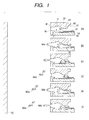
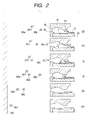
- Figs. 1 and 2 are cross-sectional views, along the liquid flow path, of a liquid discharge head constituting an embodiment of the present invention, showing feature phenomena in the liquid flow path in steps (a) to (f) in Fig. 1 and (g) to (1) in Fig. 2.
- a flat element substrate 1 is provided thereon with a heat generating member 2 as a discharge energy generating element for generating energy for discharging liquid and for giving thermal energy to the liquid, and a liquid flow path 10 is formed corresponding to the heat generating member 2 on the element substrate 1.
- the liquid flow path 10 communicates with a discharge port 18 and with a common liquid chamber 13 for supplying plural liquid flow paths 10 with the liquid, and receives, from the common liquid chamber 13, the liquid of an amount corresponding to that discharged from the discharge port 18.
- the meniscus M of the liquid filling the liquid flow path 10 is in an equilibrium state in the vicinity of the discharge port 18, by the capillary force generated by the inner wall of the discharge port 18 and the liquid flow path 10 communicating therewith and the generally negative internal pressure of the common liquid chamber 13.
- the liquid flow path 10 is constituted by adjoining of the element substrate 1 bearing the heat generating member 2 and a top plate 50, and, in the vicinity of a contact plane between the heat generating member 2 and the discharge liquid, there exists a bubble generating area for generating a bubble in the discharge liquid when the heat generating member 2 is rapidly heated.
- a movable member 31 is provided in such a manner that at least a part is opposed to the heat generating member 2.
- the movable member 31 is formed as a beam supported at an end, and has a free end 32 at the downstream side closer to the discharge port 18 and is supported by a support member 34 positioned at the upstream side of the liquid flow path 10.
- the free end 32 is positioned in the vicinity of the center of the bubble generating area (heat generating member 2), in order to suppress the growth of the upstream half of the bubble, influencing the backward wave to the upstream side and the inertial force of the liquid.
- the movable member 31 is rendered displaceable with respect to the support member 34, according to the growth of the bubble generated in the bubble generating area.
- a fulcrum 33 of such displacement constitutes an end of the supporting portion for the movable member 31 in the support member 34.
- a stopper (limiting portion) 64 is provided for limiting the displacement of the movable member 31 within a predetermined range, in order to suppress the growth of the upstream half of the bubble.
- a low flow path resistance area 65 at the upstream side of the stopper 64, having a flow path resistance lower than that in the liquid flow path 10.
- the resistance of the flow path to the liquid movement is reduced by a structure without the upper wall and with a larger cross section.
- the above-described configuration provides a characteristic head structure capable of suppressing the liquid flow toward the upstream side of the liquid flow path and the growth of the bubble toward the upstream side by the displaceable movable member.
- Figs. 1 and 2 show the states of liquid discharge from first to third droplets in three consecutive discharge operations and of landing of the discharged liquid droplet on the recording medium.
- Fig. 3 shows the change in the volume of the bubble 40 and in the displacement amount of the movable member 31.
- (a) indicates a state prior to the application of energy, such as electrical energy, to the heat generating member 2, thus prior to the heat generation thereby.
- energy such as electrical energy
- the movable member 31 is in a position (initial position) opposed to the upstream half of the bubble generated by the heat from the heat generating member 2, and that the stopper 64 for limiting the displacement of the movable member 31 is provided above the center of the bubble generating area (heat generating member 2).
- the liquid flow path and the movable member 31 are so constructed as to suppress the upstream half of the bubble. Also as shown in Fig.
- the growth of the bubble 40 causes a liquid movement to the upstream side, namely toward the common liquid chamber 13, and such movement becomes a large current because of the presence of the low flow path resistance area 65, but, when the movable member 31 is displaced to a position in contact with or close to the stopper 64, the further displacement of the movable member 31 is restricted (point B in Fig. 3) whereby the liquid movement to the upstream side is mainly suppressed at such point.
- the resistance to the liquid flow toward the upstream side (at least upstream of the center of the bubble generating area) of the liquid flow path 10 increases whereby the movement of the liquid and the bubble between the liquid flow path 10 and the common liquid chamber 13 at the upstream side thereof is significantly suppressed. Accordingly, the growth of the bubble toward the upstream side is also suppressed by the movable member 31.
- the movable member 31 since the liquid has a large moving force toward the upstream side, the movable member 31 is subjected to a strong stress toward the upstream side and is retained in a bent state, while the bubble 40 continues to grow to a maximum volume (point C in Fig. 3).
- (b) indicates a state where the bubble in the bubble generating area has grown to maximum.
- the pressure based on the bubble generation causes the liquid in the liquid flow path 10 to move toward the downstream side and the upstream side, whereby, in the upstream side, the movable member 31 is displaced by the growth of the bubble 40, while, in the downstream side, a first liquid droplet 66a is just to leave the discharge port 18.
- a "linear communication state” maintaining a straight flow path structure with respect to the liquid flow.
- Such structure is desirable in realizing an ideal state in which the propagating direction of the pressure wave generated at the bubble generation, the liquid flowing direction resulting therefrom and the liquid discharging direction preferably coincide linearly, thereby stabilizing the discharge states such as the discharge direction of the liquid droplet 66 and the discharge direction thereof at an extremely high level.
- the discharge port 18 and the heat generating member 2, particularly a portion thereof close to the discharge port (downstream side), influencing a portion of the bubble 40 at the side of the discharge port 18, can be directly connected by a straight line.
- the heat generating member 2, particularly the downstream side thereof is observable through the discharge port 18 when seen from the outside thereof in the absence of the liquid in the liquid flow path 10.
- the liquid at the upstream side is rapidly refilled as shown in (d) in Fig. 1, whereby the retraction of the meniscus M into the liquid flow path 10 can be maintained at a minimum amount.
- the first discharged liquid droplet 66a from the discharge port had a speed of 10 m/s and an amount of 6 pl.
- (d) indicates a state after the completion of a bubble extinction step and immediately before the start of application of a second electrical pulse to the heat generating member 2.
- (e) indicates a state where the second bubble in the bubble generating area has grown to maximum.
- the pressure based on the bubble generation causes the liquid in the liquid flow path 10 to move toward the downstream side and the upstream side, whereby, in the upstream side, the movable member 31 is displaced by the growth of the bubble 40, while, in the downstream side, a second liquid droplet 66b is just to leave the discharge port 18.
- the movable member 31 is in a displaced state at the start of generation of the second bubble, the liquid flow in the liquid flow path 10 toward the upstream side thereof during the bubble growth is more suppressed than that in the first bubble, whereby the discharge energy toward the downstream direction (discharging direction) is increased.
- the second liquid droplet 66b had a speed 12.5 m/s and a discharge amount of 5 pl.
- (f) indicates the repetition of a bubble extinction step similar to that shown in (c) in Fig. 1.
- (g) indicates a state after the completion of a second bubble extinction step and immediately before the start of application of a third electrical pulse to the heat generating member 2.
- the movable member starts to displace downward in the same manner as in (d) in Fig. 1, the liquid at the upstream side is rapidly refilled whereby the retraction of the meniscus M into the liquid flow path 10 can be maintained at a minimum amount.
- the displacement amount of the movable member 31 at this point is larger than that immediately before the start of generation of the second bubble.
- (h) indicates a state where the third bubble in the bubble generating area has grown to maximum.
- the pressure based on the bubble generation causes the liquid in the liquid flow path 10 to move toward the downstream side and the upstream side, whereby, in the upstream side, the movable member 31 is displaced by the growth of the bubble 40, while, in the downstream side, a third liquid droplet 66c is just to leave the discharge port 18.
- the third liquid droplet 66c had a speed 14.5 m/s and a discharge amount of 5 pl.
- (j) indicates the repetition of a refilling step similar to that shown in (d) in Fig. 1 and (g) in Fig. 2, and such refilling allows to minimize the retraction of the meniscus M into the liquid flow path 10.
- (k) indicates a state, after the consecutive discharges of three liquid droplets 66 and before the first liquid droplet 66a reaches the recording medium 150, the second liquid droplet 66b flying at a speed of 12.5 m/s reaches and is united with the first droplet flying at 10 m/s, constituting a united liquid droplet 66d consisting of the first and second droplets, having an amount of 11 pl.
- (l) indicates a state
- the third liquid droplet 66c flying at a speed of 14.5 m/s reaches and is united with the united droplet 66d formed in the state (k), constituting a united liquid droplet 66e consisting of the first, second and third droplets, having an amount of 16 pl.
- the amount of the second liquid droplet 66b is smaller than that of the first liquid droplet 66a because, at the start of the second droplet discharge, the meniscus M is somewhat retracted into the liquid flow path 10 (cf. (c) in Fig. 1), whereby the liquid amount on which the heat generating member 2 acts becomes smaller in the second discharge than in the first discharge. Because the amount of the second droplet 66b is smaller than that of the first droplet 66a in addition to a fact that the discharge energy applied to the second droplet 66b is larger than that applied to the first droplet 66a as explained in the foregoing, the second droplet has a larger discharge speed than that of the first droplet whereby the second droplet 66b can catch up the first droplet 66a.
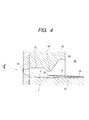
- Fig. 5 is a perspective view of a part of the head basically same as that shown in Figs. 1 and 2 except that the nozzle is removed and represented by broken lines.
- the present embodiment there are provided small clearances between the side walls constituting the liquid flow path 10 and the both sides of the movable member 31 to enable smooth displacement thereof.
- the bubble 40 displaces the movable member 31 and extends through the above-mentioned clearances to the upper side of the movable member 31, thus somewhat intruding in the low flow path resistance area 65, such extended and intruding bubble 41 extends further to the back side (opposite to the bubble generating area) of the movable member 31, thereby suppressing the vibration thereof and stabilizing the discharge characteristics.
- the extended bubble 41 stimulates the liquid flow from the low flow path resistance area 65 to the bubble generating area, thereby promptly completing the extinction of the bubble, in combination with the rapid retraction of the meniscus from the discharge port 18.
- the liquid flow induced by the extended bubble 41 almost completely prevents staying of a bubble in the corner of the movable member 31 or of the liquid flow path 10.
- discharged liquid droplets are all substantially the same in size in the above-mentioned embodiment.
- the invention is not limited to the embodiment.
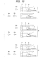
- (a) of Fig. 15 illustrates an arrangement that a discharge amount of a droplet successive to a first droplet is greater than that of the first droplet by discharging the droplet successive to the first droplet by driving a heat generating member during downward (which is a direction approaching to the heat generating member) displacement of a movable member;
- FIG. 15 illustrates an arrangement that a discharge amount of a droplet successive to a first droplet is fewer than that of the first droplet by discharging the droplet successive to the first droplet by driving a heat generating member during upward (which is a direction separating away from the heat generating member) displacement of a movable member; and further, (c) of Fig. 15 illustrates an arrangement that a discharge amount of a droplet successive to a first droplet is substantially the same as that of the first droplet by discharging the droplet successive to the first droplet by driving a heat generating member when a movable member returns to a stationary position.
- a discharge amount of the successive droplet can be controlled by changing a driving timing for discharging a droplet successive to a first droplet. That modulation of a discharge amount can stabilize a bubbling state upon discharging each droplet, thereby making error in discharge amount of droplet few.
- the upper portion of (a) of Fig. 15 shows a state immediately before a second bubble generation, where the movable member 31 is falling.
- the lower portion of (a) of Fig. 15 shows that two droplets are consecutively discharged and a discharge amount of the first droplet 66a is greater than that of the second one 66b.
- the upper portion of (b) of Fig. 15 shows a state immediately before a second bubble generation, where the movable member 31 is rising.
- the lower portion of (a) of Fig. 15 shows that two droplets are consecutively discharged and a discharge amount of the first droplet 66a is fewer than that of the second one 66b.
- the upper portion of (b) of Fig. 15 shows a state immediately before a second bubble generation, where the movable member 31 is in an initial state.
- the lower portion of (a) of Fig. 15 shows that two droplets are consecutively discharged and a discharge amount of the first droplet 66a is substantially equal to that of the second one 66b.
- the invention is not limited to the gradation recording in which a different discharge amount is discharged from a same discharge port.
- the invention is applicable to an arrangement for differentiating a discharge amount in accordance with a kind of ink.
- a discharge amount can be changed by a same heat generating member or movable member so that it is not necessary to change a layout of a heating member substrate for the modulation and a difference of discharge amount can be set without any limitation.
- FIGs. 12A and 12B are views showing a liquid discharge head of such side shooter type, wherein a heat generating member 2 on an element substrate 1 and a discharge port 18 formed on a top plate 50 are so provided as to be mutually opposed.
- the discharge port 18 communicates with a liquid flow path 10 passing on the heat generating member 2.
- a bubble generating area In the vicinity of a contact plane between the heat generating member 2 and the liquid, there is provided a bubble generating area.
- movable members 31 On the element substrate 1 there are supported two movable members 31, which are so formed as to be symmetrical with respect to a plane passing the center of the heat generating member 2 and as that the free ends of the movable members 31 are mutually opposed on the heat generating member 2.
- the movable members 31 have a same projection area on the heat generating member 2, and the free ends of the movable members 31 are separated by a desired distance.
- Each movable member 31 is so positioned, when the head is divided by an imaginary dividing wall passing through the center of the heat generating member 2, that the free end of the movable member 31 is positioned close to the center of thus divided portion of the heat generating member 2.
- the top plate 50 is provided with stoppers 64 for limiting the displacement of the movable members 31 within a certain range.
- a low flow path resistance area 65 at the upstream side of the stopper 64, having a flow path resistance lower than that in the liquid flow path 10.
- the resistance of the flow path to the liquid movement is reduced by a larger cross section than in the liquid flow path 10.
- Fig. 12A indicates a state where a part of the liquid in the bubble generating area is heated by the heat generating member 2 and a bubble 40 generated by a film boiling phenomenon has grown to maximum.
- the pressure based on the bubble generation causes the liquid in the liquid flow path 10 to move toward the discharge port 18, whereby the movable members 31 are displaced by the growth of the bubble 40, while a first liquid droplet 66a is just to leave the discharge port 18.
- the liquid movement toward the common liquid chamber 13 becomes a large current because of the presence of the low flow path resistance area 65, but, when the movable members 31 are displaced to a position in contact with or close to the stoppers 64, the further displacement of the movable members 31 is restricted whereby the liquid movement to the upstream side is also suppressed at such point. At the same time, the growth of the bubble toward the upstream side is also suppressed by the movable members 31.
- the liquid flow A is a component flowing from the common liquid chamber 18 toward the discharge port 18 through the upper side (opposite to the heat generating member 2) of the movable members 31, while the liquid flow B is a component flowing through both sides of the movable members 31 and above the heat generating member 2.
- the refilling of the liquid can be made at a higher speed by liquid supply through the low flow path resistance areas 65. Also the refilling is achieved at an even higher speed because the flow path resistance is made even lower in the common liquid chamber 13 adjacent to the low flow path resistance areas 65.
- the extended bubbles 41 stimulate the liquid flow from the low flow path resistance areas 65 to the bubble generating area, thereby promptly completing the extinction of the bubble, in combination with the rapid retraction of the meniscus from the discharge port 18.
- the liquid flows induced by the extended bubbles 41 almost completely prevent staying of a bubble in the corner of the movable members 31 or of the liquid flow path 10.
- a driving pulse is applied to the heat generating member 2 to initiate the generation of the bubble 40 after the preceding liquid discharge and before the vibration of the movable members 31 returning from the displaced state to the initial state is attenuated, namely while the movable members 31 displace toward the stoppers 64, as in the foregoing embodiment shown in Figs. 1 to 4. It is thus rendered possible to discharge the succeeding liquid droplet in the discharge direction, more efficiently than the preceding liquid droplet, thereby enabling the next liquid droplet to unite with the preceding liquid droplet before the landing thereof onto the recording medium.
- Figs. 6A to 6C show other shapes of the movable member 31, wherein Fig. 6A shows a rectangular shape; Fig. 6B shows a shape with a narrower fulcrum side to facilitate the displacement of the movable member; and Fig. 6C shows a shape with a wider fulcrum side to increase the rigidity of the movable member.
- the movable member 31 is composed of SiN of a thickness of 5 ⁇ m, but such configuration is not restrictive and the movable member may be composed of any material having resistance to the discharge liquid and elasticity for satisfactorily functioning as the movable member 31.
- the movable member is desirably composed of a material of high durability, for example a metal such as silver, nickel, gold, iron, titanium, aluminum, platinum, tantalum, stainless steel or phosphor bronze; alloys thereof; resin having nitrile radicals such as acrylonitrile, butadiene or styrene; resin having amide radicals such as polyamide; resin having carboxyl radicals such as polycarbonate; resin having aldehyde radicals such as polyacetal; resin having sulfone radicals such as polyslfone; other resins such as liquid crystal polymer and compounds thereof; or of high ink resistance, for example a metal such as gold, tungsten, tantalum, nickel, stainless steel or titanium or alloys thereof or substances surfacially coated with such metal or alloy; resin having amide radicals such as polyamide; resin having aldehyde radicals such as polyacetal; resin having ketone radicals such as polyetherether ketone; resin having imide radicals such as polyimide; resin
- the area of the heat generating member is proportional to the ink discharge amount as shown in Fig. 8, but there is present a non-effective bubble generating area S not contributing to the ink discharge. Based on the state of kogation on the heat generating member 2, such non-effective bubble generating area S is known to be present around the heat generating member. Based on these results, an area of a width of about 4 ⁇ m around the heat generating member is regarded not to contribute to the bubble generation.
- the movable member can be acted on directly above an area of the heat generating member inside such peripheral area of the width of about 4 ⁇ m.
- the approximately central area in practice a range of about ⁇ 10 ⁇ m with respect to the center along the liquid flow
- the effective bubble generating area is considered as an area of the heat generating area inside a peripheral area of a width of about 4 ⁇ m, but such area is not limited to such definition, depending on the kind of the heat generating member of the forming method thereof.
- the movable member 31 may be provided with a projection 31a (hereinafter called “downward projection”) positioned close to the bubble generating area and protruding toward the element substrate 1.
- the downward projection 31a is to suppress the growth of the bubble, generated in the bubble generating area, in the backward direction (toward the upstream side), and allows to reduce the backward growth of the bubble in comparison with the case without such lower side projections 31a. Suppressing the backward growth of the bubble 40, the downward projection 31a causes the discharge energy to effectively contribute to the ink discharge.
- the downward projection 31a is desirably provided in a position at least separate from the stepped portion around the heat generating member 2, since it may come into contact with the element substrate 1 when the movable member 31 is displaced toward the element substrate 1. More specifically, the downward projections 31a is separated at least by 5 ⁇ m from the effective bubble generating area. However, it cannot exert the effect of suppressing the backward growth of the bubble if it is excessively distant from the bubble generating area, so that it is desirably provided within a range from the effective bubble generating area of the heat generating member 2 to an approximate half of the length of the heat generating member. More specifically, in the present embodiment, the distance from the effective bubble generating area to the downward projections 31a is abut 45 ⁇ m, preferably not exceeding 30 ⁇ m and more preferably not exceeding 20 ⁇ m.
- the height of the downward projection 31a is approximately equal to or less than the distance between the movable member 31 and the element substrate 1, whereby, in the present embodiment, there is formed a slight clearance between the end of the downward projections 31a and the element substrate 1.
- Such downward projection 31a suppresses the extension of the bubble 40, generated in the bubble generating area, toward the upstream side through the gap between the movable member 31 and the element substrate 1, whereby the liquid movement to the upstream side is further reduced and the refilling characteristics can be further improved.
- the downward projection 31a substantially closes the bubble generating area at the upstream side. Therefore the pressure wave generated by the bubble generation does not proceeds to the upstream side, whereby the pressure wave can be effectively directed to the downstream side and made to contribute to the ink discharge.
- liquid discharge head utilizing such movable member 31, it is possible to consecutively discharge the liquid droplets from the same discharge port 18 and to unite the plural discharged liquid droplets thereby realizing recording of multi gradation levels.
- FIGs. 9A and 9B are schematic cross-sectional views of the liquid discharge head of the present invention, respectively with and without a protective film to be explained later.
- a top plate 50 provided with grooves for constituting the liquid flow paths 10, the discharge ports 18 communicating with the liquid flow paths 10, the low flow path resistance area 65 and the common liquid chamber 13.
- the element substrate 1 is obtained by forming, on a substrate 107 such as of silicon, a silicon oxide or silicon nitride film 106 for insulation and head accumulation, and patterning thereon an electrical resistance layer 105 (0.01 to 0.2 ⁇ m thick) of hafnium boride (HfB 2 ), tantalum nitride (TaN) or tantalum aluminum (TaAl) constituting the heat generating members 2 and wiring electrodes 104 (0.2 to 1.0 ⁇ m thick) for example of aluminum, as shown in Fig. 9A.
- a voltage is applied to the resistance layer 105 from the wiring electrodes 106 thereby generating a current in the resistance layer to generate heat therefrom.
- the anticavitation layer 102 of a metallic material such as tantalum As the pressure or impact wave generated at the generation or extinction of the bubble 40 is very strong and significantly deteriorate the durability of the hard and brittle oxide film, there is employed the anticavitation layer 102 of a metallic material such as tantalum.
- the resistance layer 105 may be so constructed as to dispense with the protective layer 103, by the suitable combination of the liquid, the configuration of the liquid flow path 10 and the material constituting the resistance layer, as illustrated in Fig. 9B.
- Such resistance layer 105 not requiring the protective layer 103 may be composed, for example, of iridium-tantalum-aluminum alloy.
- the aforementioned heat generating member 2 may be constructed by positioning the electrical resistance layer (heat generating portion) 105 between the wiring electrodes 104, or may include the protective layer 102 for protecting the electrical resistance layer 105.
- the heat generating member 2 is composed of the electrical resistance layer 105 generating heat in response to an electrical signal, but such configuration is not restrictive and there may be employed any configuration capable of generating, in the liquid, the bubble sufficient for discharging the liquid.
- the heat generating portion may be composed of an optothermal converting member capable of heat generation in response to light such as laser light, or a member capable of heat generation in response to a high frequency wave.
- the aforementioned element substrate 1 may be provided, in addition to electrothermal converting elements consisting of the electrical resistance layer 105 constituting the heat generating portions and the wiring electrodes 104 for supplying the resistance layer 105 with the electrical signal, with functional elements such as transistors, diodes, latches, shift registers etc. for selectively driving the electrothermal converting elements, integrally by a semiconductor manufacturing process.
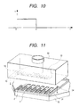
- a rectangular pulse as shown in Fig. 10 is applied to the resistance layer 105 through the wiring electrodes 104 to induce rapid heat generation in the electrical resistance layer 105 between the wiring electrodes 104.
- the heat generating member 2 was driven in the aforementioned manner by a voltage of 24 V, with a pulse duration of a ca. 4 ⁇ sec, a current of ca. 100 mA and a driving frequency of 6 kHz or higher to discharge the ink from the discharge port.
- the drive signal is not limited to such condition but can be of any condition capable of appropriate bubble generation in the liquid.
- the liquid to be used for recording can be the ink of a composition employed in the conventional bubble jet recording apparatus.
- liquid of low bubble generating property that is conventionally difficult to discharge, or liquid easily denatured or deteriorated by heat, or liquid of a high viscosity.
- Such liquid is desirably not to hinder the discharge, bubble generation or the function of the movable member 31.
- ink of a high viscosity there may also be employed ink of a high viscosity as the recording liquid.
- the recording was executed with the ink of the following composition as the recording liquid. Because the discharge speed of the ink was increased due to the higher discharging force, the landing accuracy of the liquid droplet was improved to obtain a very satisfactory recorded image.
- Composition of dye ink Dye C-1 (Food black 2) 3 wt.% diethylene glycol 10 wt.% thiodiglycol 5 wt.% ethanol 5 wt.% water 77 wt.%
- Fig. 11 is an exploded perspective view showing the entire configuration of the liquid discharge head of the present invention.
- a support member 70 composed for example of aluminum supports the element substrate 1 bearing thereon plural heat generating members 2.
- a support member 34 supporting the movable members 31 in such a manner that each movable member 31 is opposed to a half of each heat generating member 2 at the side of the common liquid chamber 13.
- the top plate 50 having plural grooves for constituting the liquid flow paths 10 and a recess for constituting the common liquid chamber 13.
- FIG. 13 schematically shows a liquid discharge apparatus including the liquid discharge head of the configuration explained in Figs. 1 and 2 or in Figs. 12A and 12B.
- an ink discharge recording apparatus employing ink as the discharge liquid.
- a carriage HC of the liquid discharge apparatus supports a head cartridge in which a liquid tank 90 containing ink and a liquid discharge head 200 are detachably mounted, and executes a reciprocating motion across the entire width of a recording medium 150, such as a recording sheet, conveyed by recording medium conveying means.
- a recording medium 150 such as a recording sheet
- the liquid discharge head 200 discharges recording liquid onto the recording medium 150.
- the liquid discharge apparatus of the present embodiment is provided with a motor 111 for driving the recording medium conveying means and the carriage, gears 112, 113 for transmitting the driving power from the drive source to the carriage, a carriage shaft 115 etc.
- a satisfactory image recording could be obtained by discharging liquid onto various recording media by the above-described recording apparatus and by the liquid discharge method executed by such recording apparatus.
- Fig. 14 is a block diagram of the entire apparatus for causing the liquid discharge head, capable of executing the liquid discharge method of the present invention, to execute ink jet recording.
- the recording apparatus receives print information, as a control signal, from a host computer 300.
- the print information is temporarily stored in an I/O interface 301 in the recording apparatus, and at the same time converted into data processable therein, and entered into a CPU (central processing unit) 302 serving also as head drive signal supply means.
- the CPU 302 processes the data entered thereto utilizing peripheral units such as a RAM 304 and based on a control program stored in a ROM 303, thereby effecting conversion into print data (image data).
- the CPU 302 also prepares drive data for driving a driving motor 306, for moving the recording sheet and the carriage HC supporting the liquid discharge head, in synchronization with the print data, in order to record the print data in an appropriate position on the recording sheet.
- the image data and the motor driving data are respectively transmitted, through a head driver 307 and a motor driver 305, to the liquid discharge head 200 and the driving motor 306 which are thus driven in respectively controlled timings to form the image.
- the recording medium 150 to be employed in such recording apparatus and to receive the deposition of liquid such as ink can be various papers, an OHP sheet, a plastic material employed in a compact disk or a decorating plate, a cloth, a metal material such as of aluminum or copper, a leather material such as cow hide, pig hide or synthetic leather, wood, a wooden material such as plywood, bamboo, ceramics such as a tile, or a three-dimensionally structured material such as sponge.
- the recording apparatus includes a printer apparatus for recording on various papers or OHP sheet, a plastic recording apparatus for recording on plastic such as a compact disk, a metal recording apparatus for recording on a metal plate, a leather recording apparatus for recording on leather, a wood recording apparatus for recording on a wooden material, a ceramic recording apparatus for recording on ceramics, a recording material for recording on a three-dimensional network structured member such as sponge, and a dyeing apparatus for recording on a cloth.
- discharge liquid to be employed in such liquid discharge apparatus can be selected according to the respective recording medium and the recording conditions.
- valve mechanism of the movable member of the liquid discharge head of the present invention suppresses the liquid movement in the upstream direction, resulting from the backward wave or the pressure wave toward the upstream side, thereby refilling of the liquid into the liquid flow path at the bubble extinction. Also in the consecutive discharging operation, the second or subsequent bubble generation in the liquid is started while the movable member is still displaced to discharge the liquid droplet more efficiently than the preceding liquid droplet and to depositing the plural liquid droplets in a united state onto the recording medium.
Landscapes
- Particle Formation And Scattering Control In Inkjet Printers (AREA)
- Ink Jet (AREA)
Abstract
Description
It is thus rendered possible to discharge the succeeding liquid droplet in the discharge direction, more efficiently than the preceding liquid droplet, thereby enabling the next liquid droplet to unite with the preceding liquid droplet before the landing thereof onto the recording medium.
| Composition of dye ink: | |
| Dye C-1 (Food black 2) | 3 wt. |
| diethylene glycol | |
| 10 wt. | |
| thiodiglycol | |
| 5 | |
| ethanol | |
| 5 wt.% | |
| water | 77 wt.% |
Claims (29)
- A liquid discharge head comprising:a heat generating member for generating thermal energy for generating a bubble in liquid;a discharge port constituting a portion for discharging said liquid;a liquid flow path communicating with said discharge port and including a bubble generating area for generating the bubble in said liquid;a movable member provided in said liquid flow path and adapted to displace according to the growth of said bubble; anda limiting portion for limiting the displacement of said movable member within a desired range and adapted to discharge said liquid from said discharge port by the energy at the generation of said bubble thereby forming a liquid droplet and to cause said liquid droplet to land on a recording medium thereby executing recording, wherein:plural liquid droplets are discharged in consecutive manner from a same discharge port and are united to form a liquid droplet prior to the landing onto said recording medium.
- A liquid discharge head according to claim 1, wherein, in case of discharging plural liquid droplets in consecutive manner from said same discharge port, said movable member is in a displaced state at the start of second or subsequent bubble generation, and the displacement amount of said movable member at the start of bubble generation is larger than the displacement amount of said movable member at the start of preceding bubble generation.
- A liquid discharge head according to claim 1, wherein, in case of discharging plural liquid droplets in consecutive manner from said same discharge port, the discharge speed of a second or subsequent liquid droplet is larger than that of a preceding liquid droplet.
- A liquid discharge head according to claim 1, wherein, in case of discharging two liquid droplets in consecutive manner, the second liquid droplet is united with the first liquid droplet before the landing thereof onto said recording medium, thereby forming a liquid droplet of an approximately doubled amount of that of the first liquid droplet.
- A liquid discharge head according to claim 1, wherein, in case of discharging three liquid droplets in consecutive manner, the second and third liquid droplets are united with the first liquid droplet before the landing thereof onto said recording medium, thereby forming a liquid droplet of an approximately tripled amount of that of the first liquid droplet.
- A liquid discharge head according to claim 1, wherein said movable member displaces to substantially close the upstream side of said liquid flow path, thereby suppressing the movement of said liquid to the upstream side and the growth of said bubble.
- A liquid discharge head according to claim 1, wherein said heat generating member is an electrothermal converting member and the heating of said liquid is executed by the supply of a driving pulse to said electrothermal converting member.
- A liquid discharge head according to claim 1, wherein the contact state between said movable member and said limiting portion is maintained for a predetermined period from the start of generation of said bubble.
- A liquid discharge head according to claim 1, wherein, in the non-displaced state of said movable member, the flow resistance of said liquid flow path at the upstream side, partitioned by said limiting portion, is lower than the flow resistance of said liquid flow path at the downstream side.
- A liquid discharge head according to claim 1, wherein said heat generating member and said discharge port are in a linearly communicating state.
- A liquid discharge head according to claim 1, wherein said movable member is provided for suppressing only the bubble growing in the upstream direction with respect to the liquid from toward said discharge port.
- A liquid discharge head according to claim 1, wherein said movable member has a free end which is positioned at the substantial center of said bubble generating area.
- A liquid discharge head according to claim 1, wherein said limiting portion is formed by partially reducing the distance of said liquid flow path from said movable member.
- A liquid discharge head according to claim 1, wherein said discharge port is provided above said heat generating member.
- A liquid discharge head according to claim 14, wherein said movable member is provided in plural units for a heat generating member, and said plural movable members are formed symmetrically to the bubble generating center of said heat generating member.
- A liquid discharge head according to claim 1, wherein, in case of discharging a plurality of liquid droplets in consecutive manner, a discharge amount of said second and subsequent liquid droplets is larger than of proceeding liquid droplet.
- A liquid discharge head according to claim 1, wherein, in case of discharging a plurality of liquid droplets in consecutive manner, a discharge amount of second and subsequent liquid droplets is smaller than that of proceeding liquid droplet.
- A liquid discharge apparatus comprising a liquid discharge head according to any of claims 1 to 17 and recording medium conveying means for conveying a recording medium for receiving the liquid discharged from said liquid discharge head.
- A liquid discharge apparatus according to claim 18, adapted to execute recording by discharging ink from said liquid discharge head and adhering ink onto a recording medium.
- A liquid discharge method for a liquid discharge head including:a heat generating member for generating thermal energy for generating a bubble in liquid;a discharge port constituting a portion for discharging said liquid;a liquid flow path communicating with said discharge port and including a bubble generating area for generating the bubble in said liquid;a movable member provided in said liquid flow path and adapted to displace according to the growth of said bubble; anda limiting portion for limiting the displacement of said movable member within a desired range and adapted to discharge said liquid from said discharge port by the energy at the generation of said bubble thereby forming a liquid droplet and to cause said liquid droplet to land on a recording medium thereby executing recording, wherein:plural liquid droplets are discharged in consecutive manner from a same discharge port and are united to form a liquid droplet prior to the landing onto said recording medium.
- A liquid discharge method according to claim 20, wherein, in said step of discharging plural liquid droplets in consecutive manner from said same discharge port, said movable member is in a displaced state at the start of second or subsequent bubble generation, and the displacement amount of said movable member at the start of bubble generation is larger than the displacement amount of said movable member at the start of preceding bubble generation.
- A liquid discharge method according to claim 20, wherein a gradation recording is executed by changing an amount of said united liquid droplets.
- A liquid discharge method according to claim 20, wherein, when discharging a plurality of liquid droplets in consecutive manner from said same discharge port, bubble generation is started for discharging a second and subsequent liquid droplets during a downward displacement of said movable member.
- A liquid discharge method according to claim 20, wherein, when discharging a plurality of liquid droplets in consecutive manner from said same discharge port, bubble generation is started for discharging a second and subsequent liquid droplets during an upward displacement of said movable member.
- A liquid discharge method according to claim 20, wherein, when discharging a plurality of liquid droplets in consecutive manner from said same discharge port, said movable member is in an initial state at a start of a second and subsequent bubble generation, and a following bubble generation is started when said movable member returns to the initial state from a displaced state where said movable member is displaced from a start of a former bubble generation.
- A liquid discharge method according to claim 20, wherein volumes of said consecutive liquid droplets are substantially a same.
- A liquid discharge method according to claim 22, wherein, when discharging a plurality of liquid droplets in consecutive manner from said same discharge port, a gradation recording is executed by changing an amount of second and subsequent liquid droplets.
- A control apparatus for controlling a liquid ejection head having a bubble generation region separated from a liquid flow path to an ejection outlet by a movable member which is displaceable in response to generation of a bubble in the bubble generation region to cause liquid ejection, wherein the control apparatus comprises drive signal supplying means for supplying drive signals to the liquid ejection head to cause generation of a second bubble after a first bubble while the movable member is still displaced as a result of the first bubble such that, in use, the first and second bubbles cause ejection of successive liquid droplets that coalesce in flight.
- A recording apparatus having a control apparatus in accordance with claim 28, and a liquid ejection head having a bubble generation region separated from a liquid flow path to an ejection outlet by a movable member which is displaceable in response to generation of a bubble in the bubble generation region to cause liquid ejection.
Applications Claiming Priority (2)
| Application Number | Priority Date | Filing Date | Title |
|---|---|---|---|
| JP21290499 | 1999-07-27 | ||
| JP21290499 | 1999-07-27 |
Publications (3)
| Publication Number | Publication Date |
|---|---|
| EP1072419A2 true EP1072419A2 (en) | 2001-01-31 |
| EP1072419A3 EP1072419A3 (en) | 2001-10-10 |
| EP1072419B1 EP1072419B1 (en) | 2004-09-29 |
Family
ID=16630219
Family Applications (1)
| Application Number | Title | Priority Date | Filing Date |
|---|---|---|---|
| EP00306403A Expired - Lifetime EP1072419B1 (en) | 1999-07-27 | 2000-07-27 | Recording apparatus and method |
Country Status (3)
| Country | Link |
|---|---|
| US (1) | US6409296B1 (en) |
| EP (1) | EP1072419B1 (en) |
| DE (1) | DE60014272T2 (en) |
Cited By (3)
| Publication number | Priority date | Publication date | Assignee | Title |
|---|---|---|---|---|
| EP1177901A1 (en) * | 2000-07-31 | 2002-02-06 | Canon Kabushiki Kaisha | Liquid discharge head, liquid discharge apparatus and liquid discharging method |
| EP1176015A3 (en) * | 2000-07-27 | 2002-04-24 | Canon Kabushiki Kaisha | Liquid discharge head, element substrate, liquid discharging apparatus and liquid discharging method |
| US6846054B2 (en) | 2000-11-10 | 2005-01-25 | Canon Kabushiki Kaisha | Liquid discharging method, image forming method, liquid discharge apparatus, and liquid discharge head |
Families Citing this family (2)
| Publication number | Priority date | Publication date | Assignee | Title |
|---|---|---|---|---|
| JP4095368B2 (en) | 2001-08-10 | 2008-06-04 | キヤノン株式会社 | Method for producing ink jet recording head |
| JP4743851B2 (en) * | 2005-07-08 | 2011-08-10 | キヤノン株式会社 | Recording head manufacturing method |
Family Cites Families (14)
| Publication number | Priority date | Publication date | Assignee | Title |
|---|---|---|---|---|
| CA1127227A (en) | 1977-10-03 | 1982-07-06 | Ichiro Endo | Liquid jet recording process and apparatus therefor |
| US4503444A (en) * | 1983-04-29 | 1985-03-05 | Hewlett-Packard Company | Method and apparatus for generating a gray scale with a high speed thermal ink jet printer |
| EP0436047A1 (en) | 1990-01-02 | 1991-07-10 | Siemens Aktiengesellschaft | Liquid jet printhead for ink jet printers |
| US5278585A (en) * | 1992-05-28 | 1994-01-11 | Xerox Corporation | Ink jet printhead with ink flow directing valves |
| EP0609997B1 (en) * | 1993-02-05 | 1998-03-18 | Hewlett-Packard Company | A system for reducing drive energy in a high speed thermal ink jet printer |
| JP3372740B2 (en) | 1995-01-13 | 2003-02-04 | キヤノン株式会社 | Liquid ejection head and liquid ejection device |
| AU4092296A (en) * | 1995-01-13 | 1996-08-08 | Canon Kabushiki Kaisha | Liquid ejecting head, liquid ejecting device and liquid ejecting method |
| DE69724330T2 (en) | 1996-06-07 | 2004-06-03 | Canon K.K. | Liquid ejecting head and apparatus and manufacturing method |
| JP3450594B2 (en) | 1996-06-07 | 2003-09-29 | キヤノン株式会社 | Liquid discharge head, liquid discharge device, and liquid discharge recording method |
| JP3542460B2 (en) | 1996-06-07 | 2004-07-14 | キヤノン株式会社 | Liquid discharge method and liquid discharge device |
| US6070970A (en) | 1996-07-11 | 2000-06-06 | Canon Kabushiki Kaisha | Liquid discharging method and liquid-discharge head, ink-jet recording method and head for ink-jet recording method |
| JP3652016B2 (en) | 1996-07-12 | 2005-05-25 | キヤノン株式会社 | Liquid discharge head and liquid discharge method |
| US6491380B2 (en) * | 1997-12-05 | 2002-12-10 | Canon Kabushiki Kaisha | Liquid discharging head with common ink chamber positioned over a movable member |
| EP0920998B1 (en) | 1997-12-05 | 2003-04-09 | Canon Kabushiki Kaisha | Liquid discharge head, liquid discharge method, head cartridge and liquid discharge device |
-
2000
- 2000-07-27 EP EP00306403A patent/EP1072419B1/en not_active Expired - Lifetime
- 2000-07-27 DE DE60014272T patent/DE60014272T2/en not_active Expired - Lifetime
- 2000-07-27 US US09/624,380 patent/US6409296B1/en not_active Expired - Fee Related
Cited By (5)
| Publication number | Priority date | Publication date | Assignee | Title |
|---|---|---|---|---|
| EP1176015A3 (en) * | 2000-07-27 | 2002-04-24 | Canon Kabushiki Kaisha | Liquid discharge head, element substrate, liquid discharging apparatus and liquid discharging method |
| US6761434B2 (en) | 2000-07-27 | 2004-07-13 | Canon Kabushiki Kaisha | Liquid discharge head, element substrate, liquid discharging apparatus and liquid discharging method |
| EP1177901A1 (en) * | 2000-07-31 | 2002-02-06 | Canon Kabushiki Kaisha | Liquid discharge head, liquid discharge apparatus and liquid discharging method |
| US6409319B1 (en) | 2000-07-31 | 2002-06-25 | Canon Kabushiki Kaisha | Liquid discharge head, liquid discharge apparatus and liquid discharging method |
| US6846054B2 (en) | 2000-11-10 | 2005-01-25 | Canon Kabushiki Kaisha | Liquid discharging method, image forming method, liquid discharge apparatus, and liquid discharge head |
Also Published As
| Publication number | Publication date |
|---|---|
| EP1072419A3 (en) | 2001-10-10 |
| DE60014272T2 (en) | 2005-10-06 |
| EP1072419B1 (en) | 2004-09-29 |
| US6409296B1 (en) | 2002-06-25 |
| DE60014272D1 (en) | 2004-11-04 |
Similar Documents
| Publication | Publication Date | Title |
|---|---|---|
| US6270199B1 (en) | Liquid ejecting head, liquid ejecting device and liquid ejecting method | |
| US6409317B1 (en) | Liquid discharge head, liquid discharge method and liquid discharge apparatus | |
| CA2278982C (en) | Liquid discharge head, liquid discharge method, and liquid discharge apparatus | |
| JPH09323420A (en) | Liquid ejection head, liquid ejection device, and liquid ejection recording method | |
| JPH09141873A (en) | Liquid ejection head, liquid ejection device, and recording method | |
| EP1072419B1 (en) | Recording apparatus and method | |
| JP3408066B2 (en) | Liquid discharge head, head cartridge using liquid discharge head, liquid discharge device, liquid discharge method, and head kit | |
| US6439701B1 (en) | Liquid discharge head, head cartridge and liquid discharge apparatus | |
| US6491382B2 (en) | Liquid discharge head and apparatus having restricted movement of a movable member | |
| JPH1076656A (en) | Liquid discharge method, liquid discharge head, head cartridge using the discharge head, and liquid discharge device | |
| JP3495920B2 (en) | Liquid discharge method, liquid discharge head, and liquid discharge device | |
| JP4194230B2 (en) | Liquid discharge method, liquid discharge head, and liquid discharge apparatus | |
| JP2000085130A (en) | Liquid discharge method, liquid discharge head, head cartridge using the discharge head, and liquid discharge device | |
| JP3706746B2 (en) | Liquid discharge head, liquid discharge method, and liquid discharge apparatus | |
| JP3495921B2 (en) | Liquid discharge method, liquid discharge head, and liquid discharge device | |
| JP2000062180A (en) | Liquid discharge head, liquid discharge method, and liquid discharge device | |
| JP3450564B2 (en) | Liquid ejection head | |
| JP3472293B2 (en) | Liquid ejection head | |
| JP3706745B2 (en) | Liquid discharge head and liquid discharge apparatus | |
| JP3619105B2 (en) | Liquid discharge head and liquid discharge apparatus | |
| JP3869948B2 (en) | Liquid ejection method | |
| AU2003271389B2 (en) | Liquid Discharge Head, Liquid Discharge Method and Liquid Discharge Apparatus | |
| JP3710206B2 (en) | Liquid ejection head, liquid ejection apparatus, and recording method | |
| JPH1071719A (en) | Liquid ejection head and liquid ejection device | |
| JPH1052914A (en) | Liquid discharge method, liquid discharge head, and liquid discharge device |
Legal Events
| Date | Code | Title | Description |
|---|---|---|---|
| PUAI | Public reference made under article 153(3) epc to a published international application that has entered the european phase |
Free format text: ORIGINAL CODE: 0009012 |
|
| AK | Designated contracting states |
Kind code of ref document: A2 Designated state(s): DE ES FR GB IT NL Kind code of ref document: A2 Designated state(s): AT BE CH CY DE DK ES FI FR GB GR IE IT LI LU MC NL PT SE |
|
| AX | Request for extension of the european patent |
Free format text: AL;LT;LV;MK;RO;SI |
|
| PUAL | Search report despatched |
Free format text: ORIGINAL CODE: 0009013 |
|
| AK | Designated contracting states |
Kind code of ref document: A3 Designated state(s): AT BE CH CY DE DK ES FI FR GB GR IE IT LI LU MC NL PT SE |
|
| AX | Request for extension of the european patent |
Free format text: AL;LT;LV;MK;RO;SI |
|
| 17P | Request for examination filed |
Effective date: 20020304 |
|
| AKX | Designation fees paid |
Free format text: DE ES FR GB IT NL |
|
| 17Q | First examination report despatched |
Effective date: 20021030 |
|
| GRAP | Despatch of communication of intention to grant a patent |
Free format text: ORIGINAL CODE: EPIDOSNIGR1 |
|
| RTI1 | Title (correction) |
Free format text: RECORDING APPARATUS AND METHOD |
|
| GRAS | Grant fee paid |
Free format text: ORIGINAL CODE: EPIDOSNIGR3 |
|
| GRAA | (expected) grant |
Free format text: ORIGINAL CODE: 0009210 |
|
| AK | Designated contracting states |
Kind code of ref document: B1 Designated state(s): DE ES FR GB IT NL |
|
| PG25 | Lapsed in a contracting state [announced via postgrant information from national office to epo] |
Ref country code: NL Free format text: LAPSE BECAUSE OF FAILURE TO SUBMIT A TRANSLATION OF THE DESCRIPTION OR TO PAY THE FEE WITHIN THE PRESCRIBED TIME-LIMIT Effective date: 20040929 |
|
| REG | Reference to a national code |
Ref country code: GB Ref legal event code: FG4D |
|
| REF | Corresponds to: |
Ref document number: 60014272 Country of ref document: DE Date of ref document: 20041104 Kind code of ref document: P |
|
| PG25 | Lapsed in a contracting state [announced via postgrant information from national office to epo] |
Ref country code: ES Free format text: LAPSE BECAUSE OF FAILURE TO SUBMIT A TRANSLATION OF THE DESCRIPTION OR TO PAY THE FEE WITHIN THE PRESCRIBED TIME-LIMIT Effective date: 20050109 |
|
| NLV1 | Nl: lapsed or annulled due to failure to fulfill the requirements of art. 29p and 29m of the patents act | ||
| PLBE | No opposition filed within time limit |
Free format text: ORIGINAL CODE: 0009261 |
|
| STAA | Information on the status of an ep patent application or granted ep patent |
Free format text: STATUS: NO OPPOSITION FILED WITHIN TIME LIMIT |
|
| ET | Fr: translation filed | ||
| 26N | No opposition filed |
Effective date: 20050630 |
|
| PGFP | Annual fee paid to national office [announced via postgrant information from national office to epo] |
Ref country code: FR Payment date: 20090722 Year of fee payment: 10 |
|
| PGFP | Annual fee paid to national office [announced via postgrant information from national office to epo] |
Ref country code: IT Payment date: 20090717 Year of fee payment: 10 |
|
| REG | Reference to a national code |
Ref country code: FR Ref legal event code: ST Effective date: 20110331 |
|
| PG25 | Lapsed in a contracting state [announced via postgrant information from national office to epo] |
Ref country code: FR Free format text: LAPSE BECAUSE OF NON-PAYMENT OF DUE FEES Effective date: 20100802 Ref country code: IT Free format text: LAPSE BECAUSE OF NON-PAYMENT OF DUE FEES Effective date: 20100727 |
|
| PGFP | Annual fee paid to national office [announced via postgrant information from national office to epo] |
Ref country code: DE Payment date: 20130731 Year of fee payment: 14 |
|
| PGFP | Annual fee paid to national office [announced via postgrant information from national office to epo] |
Ref country code: GB Payment date: 20130712 Year of fee payment: 14 |
|
| REG | Reference to a national code |
Ref country code: DE Ref legal event code: R119 Ref document number: 60014272 Country of ref document: DE |
|
| GBPC | Gb: european patent ceased through non-payment of renewal fee |
Effective date: 20140727 |
|
| PG25 | Lapsed in a contracting state [announced via postgrant information from national office to epo] |
Ref country code: DE Free format text: LAPSE BECAUSE OF NON-PAYMENT OF DUE FEES Effective date: 20150203 |
|
| REG | Reference to a national code |
Ref country code: DE Ref legal event code: R119 Ref document number: 60014272 Country of ref document: DE Effective date: 20150203 |
|
| PG25 | Lapsed in a contracting state [announced via postgrant information from national office to epo] |
Ref country code: GB Free format text: LAPSE BECAUSE OF NON-PAYMENT OF DUE FEES Effective date: 20140727 |