EP1072333A2 - Hydraulically actuated tool for mounting and dismounting rolling mill roll neck bearings - Google Patents
Hydraulically actuated tool for mounting and dismounting rolling mill roll neck bearings Download PDFInfo
- Publication number
- EP1072333A2 EP1072333A2 EP00305992A EP00305992A EP1072333A2 EP 1072333 A2 EP1072333 A2 EP 1072333A2 EP 00305992 A EP00305992 A EP 00305992A EP 00305992 A EP00305992 A EP 00305992A EP 1072333 A2 EP1072333 A2 EP 1072333A2
- Authority
- EP
- European Patent Office
- Prior art keywords
- cylinder
- axially
- bearing assembly
- ring
- roll neck
- Prior art date
- Legal status (The legal status is an assumption and is not a legal conclusion. Google has not performed a legal analysis and makes no representation as to the accuracy of the status listed.)
- Granted
Links
Images










Classifications
-
- B—PERFORMING OPERATIONS; TRANSPORTING
- B21—MECHANICAL METAL-WORKING WITHOUT ESSENTIALLY REMOVING MATERIAL; PUNCHING METAL
- B21B—ROLLING OF METAL
- B21B31/00—Rolling stand structures; Mounting, adjusting, or interchanging rolls, roll mountings, or stand frames
-
- F—MECHANICAL ENGINEERING; LIGHTING; HEATING; WEAPONS; BLASTING
- F16—ENGINEERING ELEMENTS AND UNITS; GENERAL MEASURES FOR PRODUCING AND MAINTAINING EFFECTIVE FUNCTIONING OF MACHINES OR INSTALLATIONS; THERMAL INSULATION IN GENERAL
- F16C—SHAFTS; FLEXIBLE SHAFTS; ELEMENTS OR CRANKSHAFT MECHANISMS; ROTARY BODIES OTHER THAN GEARING ELEMENTS; BEARINGS
- F16C35/00—Rigid support of bearing units; Housings, e.g. caps, covers
- F16C35/04—Rigid support of bearing units; Housings, e.g. caps, covers in the case of ball or roller bearings
- F16C35/06—Mounting or dismounting of ball or roller bearings; Fixing them onto shaft or in housing
- F16C35/078—Mounting or dismounting of ball or roller bearings; Fixing them onto shaft or in housing using pressure fluid as mounting aid
-
- B—PERFORMING OPERATIONS; TRANSPORTING
- B21—MECHANICAL METAL-WORKING WITHOUT ESSENTIALLY REMOVING MATERIAL; PUNCHING METAL
- B21B—ROLLING OF METAL
- B21B31/00—Rolling stand structures; Mounting, adjusting, or interchanging rolls, roll mountings, or stand frames
- B21B31/07—Adaptation of roll neck bearings
- B21B31/074—Oil film bearings, e.g. "Morgoil" bearings
-
- B—PERFORMING OPERATIONS; TRANSPORTING
- B21—MECHANICAL METAL-WORKING WITHOUT ESSENTIALLY REMOVING MATERIAL; PUNCHING METAL
- B21B—ROLLING OF METAL
- B21B31/00—Rolling stand structures; Mounting, adjusting, or interchanging rolls, roll mountings, or stand frames
- B21B31/08—Interchanging rolls, roll mountings, or stand frames, e.g. using C-hooks; Replacing roll chocks on roll shafts
-
- B—PERFORMING OPERATIONS; TRANSPORTING
- B21—MECHANICAL METAL-WORKING WITHOUT ESSENTIALLY REMOVING MATERIAL; PUNCHING METAL
- B21B—ROLLING OF METAL
- B21B2203/00—Auxiliary arrangements, devices or methods in combination with rolling mills or rolling methods
- B21B2203/30—Quick or bayonet couplings
-
- F—MECHANICAL ENGINEERING; LIGHTING; HEATING; WEAPONS; BLASTING
- F16—ENGINEERING ELEMENTS AND UNITS; GENERAL MEASURES FOR PRODUCING AND MAINTAINING EFFECTIVE FUNCTIONING OF MACHINES OR INSTALLATIONS; THERMAL INSULATION IN GENERAL
- F16C—SHAFTS; FLEXIBLE SHAFTS; ELEMENTS OR CRANKSHAFT MECHANISMS; ROTARY BODIES OTHER THAN GEARING ELEMENTS; BEARINGS
- F16C2322/00—Apparatus used in shaping articles
- F16C2322/12—Rolling apparatus, e.g. rolling stands, rolls
-
- Y—GENERAL TAGGING OF NEW TECHNOLOGICAL DEVELOPMENTS; GENERAL TAGGING OF CROSS-SECTIONAL TECHNOLOGIES SPANNING OVER SEVERAL SECTIONS OF THE IPC; TECHNICAL SUBJECTS COVERED BY FORMER USPC CROSS-REFERENCE ART COLLECTIONS [XRACs] AND DIGESTS
- Y10—TECHNICAL SUBJECTS COVERED BY FORMER USPC
- Y10T—TECHNICAL SUBJECTS COVERED BY FORMER US CLASSIFICATION
- Y10T29/00—Metal working
- Y10T29/53—Means to assemble or disassemble
- Y10T29/53796—Puller or pusher means, contained force multiplying operator
- Y10T29/5383—Puller or pusher means, contained force multiplying operator having fluid operator
Definitions
- This invention relates in general to bearing assemblies for rotatably supporting the necks of rolls in a rolling mill, and is concerned in particular with a portable hydraulically actuated tool which may be detachably connected to the bearing assemblies for use in axially urging the bearing assemblies into and out of seated positions on the roll necks.
- the objective of the present invention is to provide a portable hydraulically actuated tool which is adapted for detachable connection to the bearing assembly, and which is operable in both a mounting mode to urge the bearing assembly into a seated position on the roll neck, as well as in a dismounting mode to dislodge the bearing assembly from its seated position.
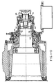
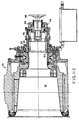
- an oil film bearing assembly generally indicated at 10 is shown mounted on the tapered neck section 12 of a roll 14 of the type found in rolling mills.
- the bearing assembly includes a sleeve 16 keyed to the roll neck as at 18.
- the sleeve is surrounded by a bushing 20 contained within a chock 22.
- the chock is adapted to be supported in a roll housing (not shown).
- oil is introduced continuously between the sleeve 16 and bushing 20, resulting in the sleeve being rotatably supported on a hydrodynamically maintained film of oil at the bearing load zone.
- the bearing assembly On its inboard side, the bearing assembly further includes a seal assembly 24.
- the outboard side of the bearing assembly includes a thrust bearing 26 having an inner race 26a and outer races contained by a thrust bearing retainer 26b, an end plate 28, a circular transfer plate 30, a lock nut 32 threaded onto a threaded ring 34, a locking element 36 mechanically coupling the threaded ring 34 to the lock nut 32, and an end cover 38 pivotally connected at 40 to the end plate 28, and held in a closed position by a latching mechanism 42.
- the distal end of the roll neck is provided with a threaded locking screw hole 43.
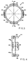
- a split bayonet adaptor 44 is seated in a circular groove 46 in a reduced diameter end section of the roll neck. As can best be seen in Figures 3 and 4, the split bayonet adaptor 44 is subdivided into two semicircular halves 44a, 44b joined together by screws 48. The adaptor is provided with radially outwardly protruding lugs 50 circumferentially spaced by flutes 52.
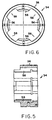
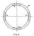
- the threaded ring 34 is externally threaded at 36, and is provided internally with inwardly protruding lugs 56 circumferentially spaced by flutes 58.
- the threaded ring is positioned as shown in Figures 1 and 2, its lugs 56 are aligned axially with the lugs 50 of the split bayonet adaptor. The threaded ring is thus axially captured between the adaptor lugs 50 and a shoulder 60 on the roll neck.
- the lock nut 32 is threaded onto the ring 34 , and in its tightened condition as shown in Figures 1 and 2, bears against the transfer plate 30, the latter in turn being held against the inner race 26a of the thrust bearing 26.
- the locking element 36 includes upper and lower parallel legs 36a, 36b joined by a web 36c.
- the upper leg 36a is configured to extend through a flute 58 between two lugs 56 of the threaded ring 34, and the lower leg 36b is secured to the lock nut 32 by one or more screws 62.
- the locking element prevents relative rotation between the lock nut 32 and the threaded ring 34.
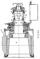
- the tool includes a cylinder 66 having a fork ring 68 fixed thereto by a cylinder cap 70.
- the fork ring has circumferentially spaced fingers 72 which project axially from the cylinder 66.
- the cylinder 66 surrounds a hollow piston 74.
- the piston has a circular external flange 74a which internally subdivides the cylinder into first and second chambers 76a, 76b.
- a locking ring 78 is mounted on and shiftable axially with respect to the cylinder 66.
- the locking ring is internally threaded at one end as at 80, and is provided with a circular inwardly projecting shoulder 82 at its opposite end.
- bayonet type lugs could be provided to mechanically coact with mating lugs on the ring 34.
- the piston 74 is provided with first and second fluid passageways 84a, 84b communicating respectively with the first and second chambers 76a, 76b.
- a locking screw 86 extends through the piston 74 and is externally threaded as at 88.
- the bearing assembly 10 is shown removed from the tapered section 12 of the roll neck.
- the split bayonet adaptor 44 is in place on the roll neck.
- the split bayonet adaptor 44 is used with rolls which do not have the lugs 50 and flutes 52 machined into their necks. When the roll necks are integrally provided with these features, the bayonet adaptor is not required.
- the threaded ring 34 is rotatably adjusted with respect to the split bayonet adaptor 44 to axially align the lugs of one component with the flutes of the other component, i.e., adaptor lugs 50 are aligned with threaded ring flutes 58, and adaptor flutes 52 are aligned with threaded ring lugs 56. With the end cover 38 in its open position, the bearing assembly is then axially mounted on the roll neck.
- the threaded ring 34 is rotated 45o to axially align its lugs 56 with the bayonet adaptor lugs 50, thereby axially fixing the threaded ring in place between the shaft shoulder 60 and the bayonet adaptor lugs 50.
- the lock nut 32 is then tightened to remove any axial play from the system.
- the tool 64 is then readied for connection to the bearing assembly 10.
- the fingers 72 of the fork ring 68 are aligned with the flutes 58 of the threaded ring 34.
- the tool is then axially inserted into its operative position (from right to left), thereby extending the fingers 72 through the threaded ring flutes 58 to abut against the transfer plate 30.
- the locking screw 86 is threaded into the locking screw hole 43 to thereby fix the piston 74 against the end of the roll neck.
- hydraulic fluid is then admitted via passageway 84a to the first chamber 76a. Because the piston 74 is fixed with respect to the roll neck, the cylinder cap 70 and fork ring 68 are urged to the left, causing the fingers 72 to bear against the transfer plate 30, which in turn bears against the inner thrust bearing race 26a. The bearing assembly is thus urged in a first direction (to the left as viewed in the illustration) into its seated position on the tapered section 12 of the roll neck. The lock nut 32 is then tightened to mechanically hold the bearing assembly in its seated position.
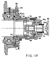
- the first step in the dismounting sequence is shown in Figure 11A.
- the end cover 38 is opened, and the locking element 36 is disengaged from the lock nut 32 and threaded ring 34.
- the tool 64 is again readied for insertion into the bearing assembly, with the fingers 72 of the fork ring 68 aligned with the flutes 58 of the threaded ring 34.
- Figure 11C shows the tool in place, with the piston 74 again secured by the locking screw 86 to the end of the roll neck.
- the second chamber 76b is pressurized by hydraulic fluid admitted via passageway 84b.
- the cylinder 66 is thus shifted in an opposite second direction with respect to the fixed piston 74 (to the right as viewed in the illustration).
- the cylinder 66 engages the shoulder 82 of the locking ring 78, causing, the locking ring, the threaded ring 34 and the lock nut 32 to move in the same direction.
- the lock nut 32 engages the end plate 28 as at 90, thereby axially pulling the bearing assembly out of its seated position on the tapered section 12 of the roll neck.
- the hydraulically actuated tool 64 of the present invention is compactly designed as an integral unit which can be readily attached and removed from the roll neck and bearing assembly.
- the tool is operable in both a mounting and dismounting mode, requiring little adjustment to shift from one mode to the other. Both operating sequences are relatively simple and straightforward, leaving little opportunity for error, while safeguarding operating personnel from injury and equipment from damage.
Landscapes
- Engineering & Computer Science (AREA)
- Mechanical Engineering (AREA)
- General Engineering & Computer Science (AREA)
- Rolls And Other Rotary Bodies (AREA)
- Mounting Of Bearings Or Others (AREA)
- Rolling Contact Bearings (AREA)
- Reduction Rolling/Reduction Stand/Operation Of Reduction Machine (AREA)
- Milling Processes (AREA)
- Support Of The Bearing (AREA)
- Bearings For Parts Moving Linearly (AREA)
- Lining Or Joining Of Plastics Or The Like (AREA)
Abstract
Description
Claims (9)
- Apparatus for axially urging a bearing assembly (10) into and out of a seated position on the neck (18) of a roll in a rolling mill, said roll neck having an end which protrudes axially from the bearing assembly when the bearing assembly is in said seated position, said apparatus comprising:a piston (74) surrounded by a cylinder (66), said piston being configured to internally subdivide said cylinder into axially separated first and second chambers 76a,76b);attachment means for removably fixing said piston to the end of said roll neck;fluid means for alternatively pressurizing said first and second chambers to alternatively shift said cylinder with respect to the thus fixed piston in opposite first and second directions;first force exerting means responsive to shifting of said cylinder in said first direction for engaging and axially urging said bearing assembly into said seated position; andsecond force exerting means responsive to shifting of said cylinder in said second direction for engaging and axially urging said bearing assembly out of said seated position.
- The apparatus as claimed in claim 1 wherein said bearing assembly includes an externally threaded ring (34), said ring having circumferentially spaced radially inwardly protruding lugs (56) coacting in a bayonet connection (44) with circumferentially spaced radially outwardly protruding lugs (50) fixed with respect to said roll neck, said ring being rotatable on said roll neck between an engaged position at which said inwardly and outwardly protruding lugs are aligned circumferentially to axially fix said ring on said roll neck, and a disengaged position at which said inwardly and outwardly protruding lugs are offset circumferentially to accommodate axial movement of said ring on said roll neck, and a lock nut (32) threaded onto said ring, said lock nut being engageable extending with first and second axially spaced thrust components of said bearing assembly.
- The apparatus as claimed in claims 1 or 2 wherein said first force exerting means comprises a first collar (68) extending axially from said cylinder for engagement with said first thrust component.
- The apparatus as claimed in claim 3 wherein said first collar includes circumferentially spaced tines (72) configured to protrude axially through complimentary spaced slots in said threaded ring.
- The apparatus as claimed in claim 3 wherein said first collar is carried by and fixed relative to said cylinder.
- The apparatus as claimed in claims 1 or 2 wherein said second force exerting means comprises a second collar (78) having one end threadedly engageable with said ring and having an opposite end axially engageable by said cylinder.
- The apparatus as claimed in claim 6 wherein said second collar is carried by and axially shiftable with respect to said cylinder.
- The apparatus as claimed in claim 1 wherein said piston, said cylinder and said first and second force exerting means are integrally combined into a unitary hydraulically actuated tool assembly.
- The apparatus as claimed in claim 1 wherein said attachment means comprises a locking screw (86) threaded into the end of said roll neck.
Applications Claiming Priority (2)
| Application Number | Priority Date | Filing Date | Title |
|---|---|---|---|
| US14628099P | 1999-07-29 | 1999-07-29 | |
| US146280P | 1999-07-29 |
Publications (3)
| Publication Number | Publication Date |
|---|---|
| EP1072333A2 true EP1072333A2 (en) | 2001-01-31 |
| EP1072333A3 EP1072333A3 (en) | 2001-05-23 |
| EP1072333B1 EP1072333B1 (en) | 2003-09-24 |
Family
ID=22516641
Family Applications (1)
| Application Number | Title | Priority Date | Filing Date |
|---|---|---|---|
| EP00305992A Expired - Lifetime EP1072333B1 (en) | 1999-07-29 | 2000-07-14 | Hydraulically actuated tool for mounting and dismounting rolling mill roll neck bearings |
Country Status (17)
| Country | Link |
|---|---|
| US (1) | US6415489B1 (en) |
| EP (1) | EP1072333B1 (en) |
| JP (1) | JP3517187B2 (en) |
| KR (1) | KR100381114B1 (en) |
| CN (1) | CN1144652C (en) |
| AT (1) | ATE250473T1 (en) |
| AU (1) | AU747718B2 (en) |
| BR (1) | BR0003214A (en) |
| CA (1) | CA2314279C (en) |
| DE (1) | DE60005443T2 (en) |
| ES (1) | ES2206143T3 (en) |
| MX (1) | MXPA00007440A (en) |
| PL (1) | PL194050B1 (en) |
| PT (1) | PT1072333E (en) |
| RU (1) | RU2212292C2 (en) |
| TW (1) | TW469181B (en) |
| ZA (1) | ZA200003615B (en) |
Cited By (9)
| Publication number | Priority date | Publication date | Assignee | Title |
|---|---|---|---|---|
| WO2001021333A3 (en) * | 1999-09-20 | 2001-10-11 | Sms Demag Ag | Device for raising and withdrawing a back-up roll bearing unit |
| EP1193003A3 (en) * | 2000-09-28 | 2003-01-15 | Morgan Construction Company | Bayonet roll end adaptor |
| WO2003022471A1 (en) * | 2001-09-04 | 2003-03-20 | Danieli & C. Officine Meccaniche S.P.A. | Hydraulic fast locking and loosening device for bearing assemblies of rolling-mill cylinders, and corresponding method of use |
| WO2005021175A1 (en) * | 2003-07-31 | 2005-03-10 | Sms Demag Aktiengesellschaft | Device for installing and removing a roller supporting a bearing assembly |
| EP1745867A1 (en) * | 2005-07-18 | 2007-01-24 | Morgan Construction Company | Oil film bearing with compact hydraulic mount |
| RU2367533C1 (en) * | 2007-01-31 | 2009-09-20 | Морган Констракшн Компани | Fluid friction bearing of rolling mill |
| US7823492B2 (en) | 2005-06-09 | 2010-11-02 | Siemens Industry, Inc. | Dual ratio drive for rotary shear |
| US8336433B2 (en) | 2009-07-21 | 2012-12-25 | Siemens Industry, Inc. | Rotary shear |
| CN104440040A (en) * | 2014-12-01 | 2015-03-25 | 郑州精益达汽车零部件有限公司 | Press for assembling oil seal seat ring, bearing inner ring and axle housing and hydraulic system of press |
Families Citing this family (38)
| Publication number | Priority date | Publication date | Assignee | Title |
|---|---|---|---|---|
| US9764453B1 (en) | 2016-03-16 | 2017-09-19 | Temper Axle Products Corporation | Systems and methods for preloading a bearing |
| US7389579B2 (en) | 2006-02-15 | 2008-06-24 | Rode John E | Apparatus for providing a load on a bearing, the bearing having an inner race mounted to a shaft and the bearing retained by a nut |
| DE102006019448A1 (en) * | 2006-04-24 | 2007-10-25 | Sms Demag Ag | puller |
| US7500374B2 (en) * | 2007-04-03 | 2009-03-10 | Morgan Construction Company | Apparatus for urging an oil film bearing onto and off of a roll neck in a rolling mill |
| US8021055B2 (en) | 2007-09-05 | 2011-09-20 | Siemens Industry, Inc. | Mechanical lock for rolling mill oil film bearing |
| CA2737064A1 (en) | 2008-09-15 | 2010-03-18 | Magna Powertrain Inc. | Sealed one way roller clutch |
| CA2737062A1 (en) * | 2008-09-15 | 2010-03-18 | Magna Powertrain Inc. | Torque transfer unit with sealed one way clutch for an engine starting system |
| US9074646B2 (en) | 2008-09-15 | 2015-07-07 | Magna Powertrain Inc. | Sealed high capacity overrunning roller clutch |
| DE102009014100A1 (en) * | 2009-03-20 | 2010-09-23 | Sms Siemag Aktiengesellschaft | Bearing arrangement for supporting roller in rolling stand, has bearing for supporting trunnion of roller in rolling stand, and circular nut with coaxially extending circular projection that is completely connected at base body of nut |
| CN101774119B (en) * | 2009-04-01 | 2011-08-10 | 燕山大学 | Roll collar quick dismounting device for hydraulic profile steel straightener |
| ES2357201B1 (en) * | 2009-04-02 | 2012-12-21 | Esteban Urreta Echarri | MECHANISM FOR QUICK CHANGE OF THE ARBOTANT BEARING. |
| CN101811249B (en) * | 2009-07-28 | 2013-09-04 | 哈尔滨轨道交通装备有限责任公司 | Bearing dismounting device |
| CN101781694B (en) * | 2010-03-23 | 2011-07-13 | 中冶宝钢技术服务有限公司 | Dismounting and transporting trolley |
| CN101913072B (en) * | 2010-08-17 | 2012-07-04 | 成都华川电装有限责任公司 | Tooling for press mounting of drive cover and bearing, and press mounting process thereof |
| DE102011104704B4 (en) * | 2011-02-25 | 2014-10-30 | Kocks Technik Gmbh & Co. Kg | Device for adjusting the axial position of an axial bearing of an axle relative to a reference component and rolling stand with such a device |
| CN102152095B (en) * | 2011-03-18 | 2012-11-28 | 浙江健力机动车部件有限公司 | Forming device for press-mounting shaft pivot bearing and water block at a time |
| CN102672458B (en) * | 2012-06-13 | 2014-04-23 | 方盛车桥(柳州)有限公司 | Press mounting machine for front axle hub bearing inner ring and press mounting method thereof |
| CN104056860B (en) * | 2014-06-10 | 2016-01-20 | 中国重型机械研究院股份公司 | Roll-box hydraulic pressure quick locking method |
| US9573178B2 (en) * | 2015-01-30 | 2017-02-21 | Novelis Inc. | Split ring and method of using improved split ring to assemble a roll |
| DE102016214011A1 (en) * | 2016-04-08 | 2017-10-12 | Sms Group Gmbh | Apparatus and method for mounting a bearing on a roll neck and for removing the bearing from the roll neck |
| US10100872B1 (en) | 2017-04-07 | 2018-10-16 | Templer Axle Products Corporation | Systems and methods for preloading a bearing and aligning a lock nut |
| US10107331B1 (en) | 2017-04-07 | 2018-10-23 | Temper Axle Products Corporation | Systems and methods for preloading a bearing and aligning a lock nut |
| US9850943B1 (en) | 2017-04-07 | 2017-12-26 | Temper Axle Products Corporation | Systems and methods for preloading a bearing and aligning a lock nut |
| US10974544B2 (en) | 2017-04-07 | 2021-04-13 | Temper Axle Products Corporation | Systems and methods for preloading a bearing and aligning a lock nut |
| DE102017217562A1 (en) | 2017-06-01 | 2018-12-06 | Sms Group Gmbh | Bearing locking device and method for its operation |
| US10982706B2 (en) | 2017-08-08 | 2021-04-20 | Temper Axle Products Corporation | Lock nut with adjustable retaining ring |
| US10107324B1 (en) | 2017-08-08 | 2018-10-23 | Temper Axle Products Corporation | Lock nut with offset retaining ring |
| US10968945B2 (en) | 2018-07-02 | 2021-04-06 | Temper Axle Products Corporation | Lock nut with rotatably alignable retaining ring |
| CN110509222A (en) * | 2019-09-11 | 2019-11-29 | 安徽马钢设备检修有限公司 | The detachment device and method for splitting of centring roll part on a kind of high-speed wheel milling train |
| CN111760910A (en) * | 2020-05-20 | 2020-10-13 | 合肥市百胜科技发展股份有限公司 | Three-roll sizing mill |
| CN114932391A (en) * | 2022-04-28 | 2022-08-23 | 华能新疆青河风力发电有限公司布尔津分公司 | Special device for dismounting bearing of generator |
| CN115533501B (en) * | 2022-12-02 | 2023-03-24 | 长沙博大科工股份有限公司 | Automatic pressing device for end cover of starting disc |
| CN115723090A (en) * | 2022-12-08 | 2023-03-03 | 上海航天设备制造总厂有限公司 | Centering assembly device for rocket overflow valve and installation method for overflow valve |
| FR3150254B1 (en) * | 2023-06-23 | 2025-06-06 | Safran Aircraft Engines | TOOLING AND METHOD FOR PRELOADING A ROLLING BEARING |
| CN117773558A (en) * | 2023-12-13 | 2024-03-29 | 中车株洲电机有限公司 | A flexible ball bearing press-fitting device |
| CN118403944B (en) * | 2024-06-28 | 2024-09-06 | 西南石油大学 | Metal bipolar plate roll forming device and manufacturing method |
| CN119458200B (en) * | 2024-10-21 | 2025-11-18 | 宁波亚洲浆纸业有限公司 | Auxiliary disassembly and assembly equipment for paper machine doctor blades |
| CN120382206B (en) * | 2025-06-27 | 2025-10-14 | 福建盛达机器股份公司 | Roller device convenient to disassemble and assemble and disassembling and assembling method |
Family Cites Families (13)
| Publication number | Priority date | Publication date | Assignee | Title |
|---|---|---|---|---|
| US3627388A (en) | 1970-09-08 | 1971-12-14 | Morgan Construction Co | Hydraulic locking and loosening device for bearing |
| US3973425A (en) * | 1974-11-07 | 1976-08-10 | Morgan Construction Company | Axial preloading device for axially adjustable grooved work rolls |
| US4286830A (en) | 1979-09-24 | 1981-09-01 | Morgan Construction Company | Combination roll neck and bearing assembly |
| US4352229A (en) | 1980-09-18 | 1982-10-05 | Bethlehem Steel Corporation | Bearing retaining and positioning means |
| JPS57199505A (en) * | 1981-06-03 | 1982-12-07 | Hitachi Ltd | Work roll moving type rolling mill |
| DE3521180C2 (en) * | 1985-02-08 | 1994-12-01 | Schloemann Siemag Ag | Device for the axial displacement of rolls in roll stands |
| DE3605615A1 (en) | 1986-02-21 | 1987-08-27 | Schloemann Siemag Ag | SHAFT PIN WITH BAYONET CLOSURE, IN PARTICULAR FOR FASTENING THE INTERNAL CYLINDER OF A HYDRAULIC DRAWING DEVICE FOR ROLLER BEARINGS ON THE ROLL PIN |
| US4813113A (en) | 1987-12-16 | 1989-03-21 | Morgan Construction Company | Overhung roll assembly |
| SU1611476A1 (en) * | 1988-09-20 | 1990-12-07 | Предприятие П/Я В-2869 | Bearing support for rolling mill roll |
| SU1653880A1 (en) * | 1989-06-08 | 1991-06-07 | Предприятие П/Я В-2869 | Device for axial adjustment of a roll |
| RU2066576C1 (en) * | 1993-04-16 | 1996-09-20 | Акционерное общество "Уральский завод тяжелого машиностроения" | Apparatus for axial adjustment of stand rolls |
| JP2640625B2 (en) * | 1994-07-12 | 1997-08-13 | 株式会社アステック | Bearing fixing device |
| DE19503682C1 (en) | 1995-01-30 | 1996-05-02 | Mannesmann Ag | Quick change unit for large rolling plates |
-
2000
- 2000-06-28 US US09/605,601 patent/US6415489B1/en not_active Expired - Lifetime
- 2000-07-14 AT AT00305992T patent/ATE250473T1/en active
- 2000-07-14 PT PT00305992T patent/PT1072333E/en unknown
- 2000-07-14 TW TW089114051A patent/TW469181B/en not_active IP Right Cessation
- 2000-07-14 EP EP00305992A patent/EP1072333B1/en not_active Expired - Lifetime
- 2000-07-14 ES ES00305992T patent/ES2206143T3/en not_active Expired - Lifetime
- 2000-07-14 DE DE60005443T patent/DE60005443T2/en not_active Expired - Lifetime
- 2000-07-18 ZA ZA200003615A patent/ZA200003615B/en unknown
- 2000-07-19 CA CA002314279A patent/CA2314279C/en not_active Expired - Lifetime
- 2000-07-21 AU AU48767/00A patent/AU747718B2/en not_active Ceased
- 2000-07-25 CN CNB001222074A patent/CN1144652C/en not_active Expired - Lifetime
- 2000-07-27 JP JP2000227627A patent/JP3517187B2/en not_active Expired - Lifetime
- 2000-07-28 MX MXPA00007440A patent/MXPA00007440A/en active IP Right Grant
- 2000-07-28 KR KR10-2000-0043610A patent/KR100381114B1/en not_active Expired - Lifetime
- 2000-07-28 PL PL341751A patent/PL194050B1/en unknown
- 2000-07-28 RU RU2000120578/02A patent/RU2212292C2/en not_active IP Right Cessation
- 2000-07-31 BR BR0003214-0A patent/BR0003214A/en not_active IP Right Cessation
Cited By (15)
| Publication number | Priority date | Publication date | Assignee | Title |
|---|---|---|---|---|
| US7082800B1 (en) | 1999-09-20 | 2006-08-01 | Sms Demag Ag | Device for raising and withdrawing a back-up roll bearing unit |
| WO2001021333A3 (en) * | 1999-09-20 | 2001-10-11 | Sms Demag Ag | Device for raising and withdrawing a back-up roll bearing unit |
| EP1193003A3 (en) * | 2000-09-28 | 2003-01-15 | Morgan Construction Company | Bayonet roll end adaptor |
| US6575638B2 (en) | 2000-09-28 | 2003-06-10 | Morgan Construction Company | Bayonet roll end adaptor |
| US7386939B2 (en) | 2001-09-04 | 2008-06-17 | Danieli + C.Officine Meccaniche S.P.A. | Hydraulic fast locking and loosening device for bearing assemblies of rolling-mill cylinders, and corresponding method of use |
| WO2003022471A1 (en) * | 2001-09-04 | 2003-03-20 | Danieli & C. Officine Meccaniche S.P.A. | Hydraulic fast locking and loosening device for bearing assemblies of rolling-mill cylinders, and corresponding method of use |
| WO2005021175A1 (en) * | 2003-07-31 | 2005-03-10 | Sms Demag Aktiengesellschaft | Device for installing and removing a roller supporting a bearing assembly |
| US7836581B2 (en) | 2003-07-31 | 2010-11-23 | Sms Siemag Aktiengesellschaft | Device for installing and removing a roller supporting a bearing assembly |
| US7823492B2 (en) | 2005-06-09 | 2010-11-02 | Siemens Industry, Inc. | Dual ratio drive for rotary shear |
| EP1745867A1 (en) * | 2005-07-18 | 2007-01-24 | Morgan Construction Company | Oil film bearing with compact hydraulic mount |
| KR100817963B1 (en) * | 2005-07-18 | 2008-03-31 | 모건 컨스트럭션 캄파니 | Oil film bearing with compact hydraulic mount |
| US7380431B2 (en) | 2005-07-18 | 2008-06-03 | Morgan Construction Company | Oil film bearing with compact hydraulic mount |
| RU2367533C1 (en) * | 2007-01-31 | 2009-09-20 | Морган Констракшн Компани | Fluid friction bearing of rolling mill |
| US8336433B2 (en) | 2009-07-21 | 2012-12-25 | Siemens Industry, Inc. | Rotary shear |
| CN104440040A (en) * | 2014-12-01 | 2015-03-25 | 郑州精益达汽车零部件有限公司 | Press for assembling oil seal seat ring, bearing inner ring and axle housing and hydraulic system of press |
Also Published As
| Publication number | Publication date |
|---|---|
| RU2212292C2 (en) | 2003-09-20 |
| DE60005443D1 (en) | 2003-10-30 |
| KR100381114B1 (en) | 2003-04-23 |
| PL341751A1 (en) | 2001-02-12 |
| US6415489B1 (en) | 2002-07-09 |
| ATE250473T1 (en) | 2003-10-15 |
| BR0003214A (en) | 2001-03-13 |
| CN1282646A (en) | 2001-02-07 |
| CN1144652C (en) | 2004-04-07 |
| ZA200003615B (en) | 2001-02-07 |
| KR20010015459A (en) | 2001-02-26 |
| JP3517187B2 (en) | 2004-04-05 |
| EP1072333A3 (en) | 2001-05-23 |
| CA2314279C (en) | 2003-12-09 |
| PT1072333E (en) | 2004-02-27 |
| AU747718B2 (en) | 2002-05-23 |
| MXPA00007440A (en) | 2002-07-22 |
| PL194050B1 (en) | 2007-04-30 |
| TW469181B (en) | 2001-12-21 |
| CA2314279A1 (en) | 2001-01-29 |
| DE60005443T2 (en) | 2004-06-03 |
| EP1072333B1 (en) | 2003-09-24 |
| ES2206143T3 (en) | 2004-05-16 |
| JP2001065583A (en) | 2001-03-16 |
| AU4876700A (en) | 2001-02-01 |
Similar Documents
| Publication | Publication Date | Title |
|---|---|---|
| EP1072333B1 (en) | Hydraulically actuated tool for mounting and dismounting rolling mill roll neck bearings | |
| US3002769A (en) | Rotary union having particular assembly means | |
| KR100862913B1 (en) | Pinion Mounts for Differential Gear Units and How to Mount Pinions in Differential Gear Units | |
| US4286830A (en) | Combination roll neck and bearing assembly | |
| EP1425117B1 (en) | Hydraulic fast locking and loosening device for bearing assemblies of rolling-mill cylinders, and corresponding method of use | |
| US5934131A (en) | Overhung roll assembly | |
| CA2387989A1 (en) | Device for mounting and demounting a back-up roll bearing unit | |
| EP1193003B1 (en) | Bayonet roll end adaptor | |
| US20040112107A1 (en) | Roll stand for rolling bar-shaped or tubular stock | |
| US4881310A (en) | Overhung roll assembly | |
| JP2752041B2 (en) | Methods and tools for installing and removing roll rings | |
| AU754587B2 (en) | Bayonet roll end adaptor | |
| JP2640625B2 (en) | Bearing fixing device | |
| CA1301561C (en) | Frictional joints | |
| JPH0861379A (en) | Bearing fixing device | |
| JP2984627B2 (en) | Rolling roll bearing fixing device |
Legal Events
| Date | Code | Title | Description |
|---|---|---|---|
| PUAI | Public reference made under article 153(3) epc to a published international application that has entered the european phase |
Free format text: ORIGINAL CODE: 0009012 |
|
| 17P | Request for examination filed |
Effective date: 20000727 |
|
| AK | Designated contracting states |
Kind code of ref document: A2 Designated state(s): AT BE CH CY DE DK ES FI FR GB GR IE IT LI LU MC NL PT SE |
|
| AX | Request for extension of the european patent |
Free format text: AL;LT;LV;MK;RO;SI |
|
| PUAL | Search report despatched |
Free format text: ORIGINAL CODE: 0009013 |
|
| AK | Designated contracting states |
Kind code of ref document: A3 Designated state(s): AT BE CH CY DE DK ES FI FR GB GR IE IT LI LU MC NL PT SE |
|
| AX | Request for extension of the european patent |
Free format text: AL;LT;LV;MK;RO;SI |
|
| AKX | Designation fees paid |
Free format text: AT BE CH CY DE DK ES FI FR GB GR IE IT LI LU MC NL PT SE |
|
| GRAH | Despatch of communication of intention to grant a patent |
Free format text: ORIGINAL CODE: EPIDOS IGRA |
|
| GRAH | Despatch of communication of intention to grant a patent |
Free format text: ORIGINAL CODE: EPIDOS IGRA |
|
| GRAA | (expected) grant |
Free format text: ORIGINAL CODE: 0009210 |
|
| AK | Designated contracting states |
Kind code of ref document: B1 Designated state(s): AT BE CH CY DE DK ES FI FR GB GR IE IT LI LU MC NL PT SE |
|
| PG25 | Lapsed in a contracting state [announced via postgrant information from national office to epo] |
Ref country code: CY Free format text: LAPSE BECAUSE OF FAILURE TO SUBMIT A TRANSLATION OF THE DESCRIPTION OR TO PAY THE FEE WITHIN THE PRESCRIBED TIME-LIMIT Effective date: 20030924 |
|
| REG | Reference to a national code |
Ref country code: GB Ref legal event code: FG4D |
|
| REG | Reference to a national code |
Ref country code: CH Ref legal event code: EP |
|
| REG | Reference to a national code |
Ref country code: IE Ref legal event code: FG4D |
|
| REF | Corresponds to: |
Ref document number: 60005443 Country of ref document: DE Date of ref document: 20031030 Kind code of ref document: P |
|
| PG25 | Lapsed in a contracting state [announced via postgrant information from national office to epo] |
Ref country code: DK Free format text: LAPSE BECAUSE OF FAILURE TO SUBMIT A TRANSLATION OF THE DESCRIPTION OR TO PAY THE FEE WITHIN THE PRESCRIBED TIME-LIMIT Effective date: 20031224 |
|
| REG | Reference to a national code |
Ref country code: CH Ref legal event code: NV Representative=s name: ISLER & PEDRAZZINI AG |
|
| REG | Reference to a national code |
Ref country code: SE Ref legal event code: TRGR |
|
| REG | Reference to a national code |
Ref country code: GR Ref legal event code: EP Ref document number: 20030405047 Country of ref document: GR |
|
| REG | Reference to a national code |
Ref country code: ES Ref legal event code: FG2A Ref document number: 2206143 Country of ref document: ES Kind code of ref document: T3 |
|
| ET | Fr: translation filed | ||
| PG25 | Lapsed in a contracting state [announced via postgrant information from national office to epo] |
Ref country code: IE Free format text: LAPSE BECAUSE OF NON-PAYMENT OF DUE FEES Effective date: 20040714 |
|
| PLBE | No opposition filed within time limit |
Free format text: ORIGINAL CODE: 0009261 |
|
| STAA | Information on the status of an ep patent application or granted ep patent |
Free format text: STATUS: NO OPPOSITION FILED WITHIN TIME LIMIT |
|
| PG25 | Lapsed in a contracting state [announced via postgrant information from national office to epo] |
Ref country code: MC Free format text: LAPSE BECAUSE OF NON-PAYMENT OF DUE FEES Effective date: 20040731 |
|
| 26N | No opposition filed |
Effective date: 20040625 |
|
| PG25 | Lapsed in a contracting state [announced via postgrant information from national office to epo] |
Ref country code: PT Free format text: LAPSE BECAUSE OF NON-PAYMENT OF DUE FEES Effective date: 20050114 |
|
| PG25 | Lapsed in a contracting state [announced via postgrant information from national office to epo] |
Ref country code: NL Free format text: LAPSE BECAUSE OF NON-PAYMENT OF DUE FEES Effective date: 20050201 |
|
| PG25 | Lapsed in a contracting state [announced via postgrant information from national office to epo] |
Ref country code: GR Free format text: LAPSE BECAUSE OF NON-PAYMENT OF DUE FEES Effective date: 20050203 |
|
| REG | Reference to a national code |
Ref country code: PT Ref legal event code: MM4A Free format text: LAPSE DUE TO NON-PAYMENT OF FEES Effective date: 20050114 |
|
| NLV4 | Nl: lapsed or anulled due to non-payment of the annual fee |
Effective date: 20050201 |
|
| REG | Reference to a national code |
Ref country code: IE Ref legal event code: MM4A |
|
| REG | Reference to a national code |
Ref country code: CH Ref legal event code: PCAR Free format text: ISLER & PEDRAZZINI AG;POSTFACH 1772;8027 ZUERICH (CH) |
|
| REG | Reference to a national code |
Ref country code: CH Ref legal event code: NV Representative=s name: SIEMENS SCHWEIZ AG |
|
| REG | Reference to a national code |
Ref country code: CH Ref legal event code: PFA Owner name: SIEMENS INDUSTRY, INC. Free format text: MORGAN CONSTRUCTION COMPANY#15 BELMONT STREET#WORCESTER MASSACHUSETTS 01605 (US) -TRANSFER TO- SIEMENS INDUSTRY, INC.#3333 OLD MILTON PARKWAY#ALPHARETTA, GA 30005 (US) |
|
| REG | Reference to a national code |
Ref country code: GB Ref legal event code: 732E Free format text: REGISTERED BETWEEN 20110310 AND 20110316 |
|
| REG | Reference to a national code |
Ref country code: DE Ref legal event code: R081 Ref document number: 60005443 Country of ref document: DE Owner name: SIEMENS INDUSTRY, INC. (N. D. GES. D. STAATES , US Free format text: FORMER OWNER: MORGAN CONSTRUCTION CO., WORCESTER, MASS., US Effective date: 20110209 Ref country code: DE Ref legal event code: R081 Ref document number: 60005443 Country of ref document: DE Owner name: PRIMETALS TECHNOLOGIES USA LLC, ALPHARETTA, US Free format text: FORMER OWNER: MORGAN CONSTRUCTION CO., WORCESTER, MASS., US Effective date: 20110209 |
|
| REG | Reference to a national code |
Ref country code: ES Ref legal event code: PC2A Owner name: SIEMENS INDUSTRY, INC. Effective date: 20110428 |
|
| REG | Reference to a national code |
Ref country code: FR Ref legal event code: TP |
|
| PGFP | Annual fee paid to national office [announced via postgrant information from national office to epo] |
Ref country code: LU Payment date: 20120720 Year of fee payment: 13 |
|
| PGFP | Annual fee paid to national office [announced via postgrant information from national office to epo] |
Ref country code: GB Payment date: 20120709 Year of fee payment: 13 |
|
| PGFP | Annual fee paid to national office [announced via postgrant information from national office to epo] |
Ref country code: CH Payment date: 20121011 Year of fee payment: 13 |
|
| REG | Reference to a national code |
Ref country code: CH Ref legal event code: PL |
|
| GBPC | Gb: european patent ceased through non-payment of renewal fee |
Effective date: 20130714 |
|
| PG25 | Lapsed in a contracting state [announced via postgrant information from national office to epo] |
Ref country code: GB Free format text: LAPSE BECAUSE OF NON-PAYMENT OF DUE FEES Effective date: 20130714 Ref country code: LI Free format text: LAPSE BECAUSE OF NON-PAYMENT OF DUE FEES Effective date: 20130731 Ref country code: CH Free format text: LAPSE BECAUSE OF NON-PAYMENT OF DUE FEES Effective date: 20130731 |
|
| PG25 | Lapsed in a contracting state [announced via postgrant information from national office to epo] |
Ref country code: LU Free format text: LAPSE BECAUSE OF NON-PAYMENT OF DUE FEES Effective date: 20130714 |
|
| REG | Reference to a national code |
Ref country code: FR Ref legal event code: PLFP Year of fee payment: 17 |
|
| REG | Reference to a national code |
Ref country code: DE Ref legal event code: R082 Ref document number: 60005443 Country of ref document: DE Representative=s name: KINNSTAETTER, KLAUS, DIPL.-PHYS.UNIV., DE Ref country code: DE Ref legal event code: R081 Ref document number: 60005443 Country of ref document: DE Owner name: PRIMETALS TECHNOLOGIES USA LLC, ALPHARETTA, US Free format text: FORMER OWNER: SIEMENS INDUSTRY, INC. (N. D. GES. D. STAATES DELAWARE), BUFFALO GROVE, III., US |
|
| REG | Reference to a national code |
Ref country code: FR Ref legal event code: TP Owner name: PRIMETALS TECHNOLOGIES USA LLC, US Effective date: 20160928 |
|
| REG | Reference to a national code |
Ref country code: ES Ref legal event code: PC2A Owner name: PRIMETALS TECHNOLOGIES USA LLC Effective date: 20161220 |
|
| REG | Reference to a national code |
Ref country code: FR Ref legal event code: PLFP Year of fee payment: 18 |
|
| REG | Reference to a national code |
Ref country code: AT Ref legal event code: PC Ref document number: 250473 Country of ref document: AT Kind code of ref document: T Owner name: PRIMETALS TECHNOLOGIES USA LLC, US Effective date: 20170706 |
|
| REG | Reference to a national code |
Ref country code: FR Ref legal event code: PLFP Year of fee payment: 19 |
|
| PGFP | Annual fee paid to national office [announced via postgrant information from national office to epo] |
Ref country code: FR Payment date: 20190719 Year of fee payment: 20 Ref country code: IT Payment date: 20190730 Year of fee payment: 20 Ref country code: ES Payment date: 20190822 Year of fee payment: 20 Ref country code: DE Payment date: 20190719 Year of fee payment: 20 Ref country code: SE Payment date: 20190719 Year of fee payment: 20 Ref country code: FI Payment date: 20190722 Year of fee payment: 20 |
|
| PGFP | Annual fee paid to national office [announced via postgrant information from national office to epo] |
Ref country code: BE Payment date: 20190718 Year of fee payment: 20 |
|
| PGFP | Annual fee paid to national office [announced via postgrant information from national office to epo] |
Ref country code: AT Payment date: 20190722 Year of fee payment: 20 |
|
| REG | Reference to a national code |
Ref country code: DE Ref legal event code: R071 Ref document number: 60005443 Country of ref document: DE |
|
| REG | Reference to a national code |
Ref country code: FI Ref legal event code: MAE |
|
| REG | Reference to a national code |
Ref country code: BE Ref legal event code: MK Effective date: 20200714 |
|
| REG | Reference to a national code |
Ref country code: SE Ref legal event code: EUG |
|
| REG | Reference to a national code |
Ref country code: AT Ref legal event code: MK07 Ref document number: 250473 Country of ref document: AT Kind code of ref document: T Effective date: 20200714 |
|
| REG | Reference to a national code |
Ref country code: SE Ref legal event code: EUG |
|
| REG | Reference to a national code |
Ref country code: ES Ref legal event code: FD2A Effective date: 20201028 |
|
| PG25 | Lapsed in a contracting state [announced via postgrant information from national office to epo] |
Ref country code: ES Free format text: LAPSE BECAUSE OF EXPIRATION OF PROTECTION Effective date: 20200715 |