CN101781694B - Dismounting and transporting trolley - Google Patents
Dismounting and transporting trolley Download PDFInfo
- Publication number
- CN101781694B CN101781694B CN2010101312074A CN201010131207A CN101781694B CN 101781694 B CN101781694 B CN 101781694B CN 2010101312074 A CN2010101312074 A CN 2010101312074A CN 201010131207 A CN201010131207 A CN 201010131207A CN 101781694 B CN101781694 B CN 101781694B
- Authority
- CN
- China
- Prior art keywords
- frame body
- dismounting
- lower frame
- trolley
- dolly
- Prior art date
- Legal status (The legal status is an assumption and is not a legal conclusion. Google has not performed a legal analysis and makes no representation as to the accuracy of the status listed.)
- Expired - Fee Related
Links
- 210000003041 ligament Anatomy 0.000 claims description 12
- 239000000463 material Substances 0.000 abstract description 24
- 238000010276 construction Methods 0.000 abstract description 5
- 230000002829 reductive effect Effects 0.000 abstract description 4
- XEEYBQQBJWHFJM-UHFFFAOYSA-N Iron Chemical compound [Fe] XEEYBQQBJWHFJM-UHFFFAOYSA-N 0.000 abstract 2
- 238000003723 Smelting Methods 0.000 abstract 1
- 229910052742 iron Inorganic materials 0.000 abstract 1
- 101100298222 Caenorhabditis elegans pot-1 gene Proteins 0.000 description 3
- 239000004744 fabric Substances 0.000 description 3
- 238000005516 engineering process Methods 0.000 description 2
- 239000002360 explosive Substances 0.000 description 2
- 238000000034 method Methods 0.000 description 2
- 230000009286 beneficial effect Effects 0.000 description 1
- 239000003795 chemical substances by application Substances 0.000 description 1
- 239000003245 coal Substances 0.000 description 1
- 230000006835 compression Effects 0.000 description 1
- 238000007906 compression Methods 0.000 description 1
- 230000007812 deficiency Effects 0.000 description 1
- 238000010586 diagram Methods 0.000 description 1
- 230000007613 environmental effect Effects 0.000 description 1
- 239000000446 fuel Substances 0.000 description 1
- 230000004927 fusion Effects 0.000 description 1
- 238000004519 manufacturing process Methods 0.000 description 1
- 239000008188 pellet Substances 0.000 description 1
- 239000002994 raw material Substances 0.000 description 1
Images


Abstract
The invention discloses a dismounting and transporting trolley comprising an upper trolley and a lower trolley. The upper trolley is located above the lower trolley and comprises a closed upper frame, roller wheels are arranged at the bottom of the upper frame, and the upper frame is also provided with two support bars arranged in parallel; the lower trolley comprises a lower frame with an opening at one end, the roller wheels are arranged at the bottom of the lower frame, and the lower frame is detachably connected to the upper frame. The dismounting and transporting trolley has simple structure and convenient operation, the dismounting and the transporting of a material flow valve and a corrugated pipe in a COREX (Iron Making By Smelting Reduction)-C3000 shaft furnace can be quickly realized, the labor intensity of an operator is reduced, the construction time is shortened, the replacing speed of an ore charge distributor is quickened and the working efficiency is improved.
Description
Technical field
The present invention relates to a kind of dismounting and transporting trolley, particularly a kind of dismounting and transporting trolley that is used for material valve and corrugated tube on the COREX-C3000 shaft furnace.
Background technology
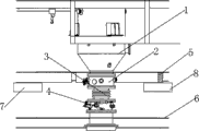
COREX is used lump ore or pellet to make raw material, is used mill coal to make the ironmaking technique of fusion and reduction of reductive agent and fuel by VAI exploitation a kind of.The COREX-C3000 shaft furnace is a kind of ironmaking shaft furnace of very advanced at present and environmental protection, its inside is provided with an ore distributor mechanism, this ore distributor mechanism can be to carrying out dynamic ore cloth in the stove, its mounting structure as shown in Figure 1, ore distributor 4 is positioned at the below of feed pot 1, feed pot 1 is connected with ore distributor 4 with corrugated tube 3 by material valve 2, and ore distributor 4 is between first platform 5 and second platform 6.This ore distributor 4 wearing and tearing can occur after using for some time, the uneven problem of cloth can appear in the ore distributor 4 after the wearing and tearing when cloth, therefore will periodically change operation to ore distributor 4.When the COREX-C3000 shaft furnace is changed the construction of ore distributor, need can change operation with after its top corrugated tube 3 and material valve 2 dismountings.Ore distributor 4 between first platform 5 and second platform 6, close together between two platforms, so the space, working-yard is narrow and small, corrugated tube 3 and the material valve 2 pulled down need be had bad luck the next door, could not influence normal construction.But it is because less at interval between first platform 5 and second platform 6, large-scale apparatus can't enter, the both sides of ore distributor 4 also are provided with obstacle 7,8, corrugated tube 3 and material valve 2 also can only outwards be had bad luck with lower height, therefore can only use manpower to dismantle and carry at present, labour intensity is very big, and the engineering time is long, inefficiency, and then may have influence on production schedule in addition.
Summary of the invention
At above-mentioned the deficiencies in the prior art, the technical problem to be solved in the present invention provides a kind of simple in structure, the dolly that can make things convenient for material valve, corrugated tube dismounting and have bad luck in small space.
For solving the problems of the technologies described above, the present invention adopts following technical scheme:
A kind of dismounting and transporting trolley, it comprises: a top dolly and a bottom dolly, described top dolly is positioned at dolly top, described bottom, described top dolly comprises a upper frame body, the bottom of described upper frame body is provided with roller, also is provided with two support bars on the described upper frame body, and described bottom dolly comprises the lower frame body of one one end opening, described lower frame body bottom is provided with roller, and described lower frame body is dismountable to be connected on the described upper frame body.
Preferably, described support bar is provided with corrugated tube flange face fixed orifices.
Preferably, described two support bars are arranged in parallel.
Preferably, described upper frame body is connected to form successively by four upper ledge baffle plates, is provided with diagonal ligament between the adjacent upper ledge baffle plate.
Preferably, described lower frame body is connected to form successively by three lower frame baffle plates, is provided with down diagonal ligament between the adjacent lower frame baffle plate.
Preferably, be equipped with hanger on described upper frame body and the described lower frame body.
Technique scheme has following beneficial effect: this dismounting and transporting trolley in use, at first place the below of COREX-C3000 shaft furnace corrugated tube flange face by two support bars of top dolly, then material valve is pulled down from the filling tube of feed pot, the corrugated tube flange is dropped on two support bars, again corrugated tube is pulled down from the ore distributor, mobile dismounting and transporting trolley can be with material valve, corrugated tube shifts out between feed pot and ore distributor, then the bottom dolly is removed from the top dolly, reduce the height of top dolly, make material valve and corrugated tube smoothly the cut-through thing had bad luck out.This shows that this dismounting and transporting trolley can make things convenient for the dismounting of material valve and corrugated tube in the COREX-C3000 shaft furnace and has bad luck, reduced labor intensity of operating personnel, shortened the time of construction, improved working efficiency.
Description of drawings
Fig. 1 is the installing mechanism synoptic diagram of COREX-C3000 shaft furnace ore distributor.
Fig. 2 is the structural representation of the embodiment of the invention.
Fig. 3 is the explosive view of embodiment of the invention top dolly.
Fig. 4 is the explosive view of embodiment of the invention bottom dolly.
Structural representation when Fig. 5 is material valve, corrugated tube dismounting.
Fig. 6 is a material valve, the structural representation when corrugated tube shifts out.
Fig. 7 is a material valve, the structural representation when corrugated tube is had bad luck.
Embodiment
Below in conjunction with accompanying drawing the preferred embodiments of the present invention are described in detail.
As shown in Figure 2, this dismounting and transporting trolley comprises a top dolly 10 and a bottom dolly 20, and top dolly 10 is positioned at the top of bottom dolly 20, and bottom dolly 20 is connected on the top dolly 10 by bolt is dismountable.Top dolly 10 is provided with two support bars that are arranged in parallel 11, and support bar 11 is provided with corrugated tube flange face fixed orifices 12, and the threaded hole on corrugated tube flange face fixed orifices 12 and the COREX-C3000 shaft furnace on the corrugated tube flange face is corresponding.
As shown in Figure 3, top dolly 10 comprises the upper frame body of a closure, this upper frame body is connected to form successively by four upper ledge baffle plates 14,15,16,17, be provided with diagonal ligament 19 between the upper ledge baffle plate 14,15, be provided with diagonal ligament 39 between the upper ledge baffle plate 15,16, be provided with diagonal ligament 38 between the upper ledge baffle plate 16,17, be provided with diagonal ligament 18 between the upper ledge baffle plate 17,14, last diagonal ligament 18,19,38,39 can make upper frame body more firm, and four angles, the bottom of upper frame body are respectively equipped with a roller 13.Be equipped with the hanger that is used to lift on the upper ledge baffle plate 14,15,16,17.
As shown in Figure 4, bottom dolly 20 comprises the lower frame body of one one end opening, this lower frame body is connected to form successively by three lower frame baffle plates 22,23,24, be provided with down diagonal ligament 25,26 between the lower frame baffle plate 22,23, be provided with down diagonal ligament 27,28 between the lower frame baffle plate 23,24, following diagonal ligament 25,26,27,28 can make lower frame body more firm, and four angles, the bottom of lower frame body are respectively equipped with a roller 21.Be equipped with the hanger that is used to lift on the lower frame baffle plate 22,23,24.
As shown in Figure 5, when material valve 2 on dismounting COREX-C3000 shaft furnace and corrugated tube 3, at first this dismounting and transporting trolley is assembled around material valve 2 and corrugated tube 3, make the bottom of corrugated tube 3 be positioned at the upper frame body of top dolly 10.Two support bars 11 are placed the below of corrugated tube ring flange 31, then material valve 2 is pulled down from the filling tube of feed pot 1, corrugated tube ring flange 31 is dropped on two support bars 11, the threaded hole and the corrugated tube flange face fixed orifices 12 that connect corrugated tube ring flange 31 by bolt, corrugated tube ring flange 31 is fixed on the support bar 11, and then the joint bolt between dismounting corrugated tube 3 and the ore distributor 4, and the compression bolt compress bellows of utilizing corrugated tube 3 to carry, make between the part of corrugated tube 2 and material valve 2 one and the ore distributor 4 and produce the gap.
As shown in Figure 6, driving 9 is set above this dismounting and transporting trolley, and it is connected with hanger on this dismounting and transporting trolley, 9 this dismounting and transporting trolley outwards pulled out along the opening direction of lower frame body by driving a vehicle then with wireline.Because a side of pull-out direction also is provided with obstacle 7, the height of obstacle 7 is lower than the height of material valve 2, so material valve 2 and corrugated tube 3 still can not be had bad luck out fully.This moment can be as shown in Figure 7, bottom dolly 20 is removed from top dolly 10, the top dolly is dropped on second platform 6, thereby reduce the height of material valve 2, make the height of material valve 2 be lower than the height of obstacle 7, material valve 2 and corrugated tube 3 just can be had bad luck out smoothly like this, make the replacing operation of ore distributor more convenient.
This dismounting and transporting trolley is simple in structure, and is easy to operate, can realize the dismounting of material valve and corrugated tube in the COREX-C3000 shaft furnace fast and has bad luck, reduced labor intensity of operating personnel, shorten the time of construction, accelerated the replacing speed of ore distributor, improved working efficiency.
The dismounting and transporting trolley that the embodiment of the invention provided is described in detail; for one of ordinary skill in the art; thought according to the embodiment of the invention; part in specific embodiments and applications all can change; in sum; this description should not be construed as limitation of the present invention, and all any changes of making according to design philosophy of the present invention are all within protection scope of the present invention.
Claims (1)
1. dismounting and transporting trolley, it is characterized in that: it comprises a top dolly and a bottom dolly, described top dolly is positioned at dolly top, described bottom, described top dolly comprises a upper frame body, the bottom of described upper frame body is provided with roller, also be provided with two support bars on the described upper frame body, described support bar is provided with corrugated tube flange face fixed orifices, described two support bars are arranged in parallel, described bottom dolly comprises the lower frame body of one one end opening, described lower frame body bottom is provided with roller, and described lower frame body is dismountable to be connected on the described upper frame body, and described upper frame body is connected to form successively by four upper ledge baffle plates, be provided with diagonal ligament between the adjacent upper ledge baffle plate, described lower frame body is connected to form successively by three lower frame baffle plates, is provided with down diagonal ligament between the adjacent lower frame baffle plate, is equipped with hanger on described upper frame body and the described lower frame body.
Priority Applications (1)
| Application Number | Priority Date | Filing Date | Title |
|---|---|---|---|
| CN2010101312074A CN101781694B (en) | 2010-03-23 | 2010-03-23 | Dismounting and transporting trolley |
Applications Claiming Priority (1)
| Application Number | Priority Date | Filing Date | Title |
|---|---|---|---|
| CN2010101312074A CN101781694B (en) | 2010-03-23 | 2010-03-23 | Dismounting and transporting trolley |
Publications (2)
| Publication Number | Publication Date |
|---|---|
| CN101781694A CN101781694A (en) | 2010-07-21 |
| CN101781694B true CN101781694B (en) | 2011-07-13 |
Family
ID=42521847
Family Applications (1)
| Application Number | Title | Priority Date | Filing Date |
|---|---|---|---|
| CN2010101312074A Expired - Fee Related CN101781694B (en) | 2010-03-23 | 2010-03-23 | Dismounting and transporting trolley |
Country Status (1)
| Country | Link |
|---|---|
| CN (1) | CN101781694B (en) |
Family Cites Families (5)
| Publication number | Priority date | Publication date | Assignee | Title |
|---|---|---|---|---|
| JPH0930423A (en) * | 1995-07-19 | 1997-02-04 | Kobayashi Hansou Kiki:Kk | Load lifter lock mechanism for carrying truck |
| US6415489B1 (en) * | 1999-07-29 | 2002-07-09 | Morgan Construction Company | Hydraulically actuated tool for mounting and dismounting rolling mill roll neck bearings |
| DE19945070A1 (en) * | 1999-09-20 | 2001-03-22 | Sms Demag Ag | Device for mounting and removing a support roller bearing unit |
| CN201272666Y (en) * | 2008-09-25 | 2009-07-15 | 上海宝钢设备检修有限公司 | Special slings for sealing and replacing helical cooling water apparatus of COREX ironmaking furnace |
| CN201339042Y (en) * | 2008-12-16 | 2009-11-04 | 上海宝钢设备检修有限公司 | Special disassembly and assembly trolley for COREX iron-making furnace Y-shaped blanking tube stifle |
-
2010
- 2010-03-23 CN CN2010101312074A patent/CN101781694B/en not_active Expired - Fee Related
Also Published As
| Publication number | Publication date |
|---|---|
| CN101781694A (en) | 2010-07-21 |
Similar Documents
| Publication | Publication Date | Title |
|---|---|---|
| CN205616840U (en) | Dry coke quenching device of packing into | |
| CN201155927Y (en) | Walking beam type heating stove dregs-scraping device | |
| CN204151402U (en) | A kind of vananum smelting furnace | |
| CN205128910U (en) | Ware is drawn at mouth of a river | |
| CN101781694B (en) | Dismounting and transporting trolley | |
| CN204268902U (en) | A kind of electric induction furnace steel scrap continuously pre-heating promotes feeding device | |
| CN103805216A (en) | Tamping station with 7.63m top-mounted coke oven improved into tamping coking | |
| CN102553670A (en) | Double-tooth roller red coke crusher | |
| CN105344414A (en) | Crusher | |
| CN202410735U (en) | Double-gear-roller red coke crusher | |
| CN214288397U (en) | Broken bin outlet of cone crusher | |
| CN201713528U (en) | Distribution chute overhauling device | |
| CN201272666Y (en) | Special slings for sealing and replacing helical cooling water apparatus of COREX ironmaking furnace | |
| CN201240690Y (en) | Bolt fixing type carrying idler roller support | |
| CN202704489U (en) | Dredging device of raw coal belt conveyor head flowing opening | |
| CN212833850U (en) | Improved blast furnace receiving hopper | |
| CN102374786B (en) | Hot aggregate bin capable of automatically receiving and feeding materials and hot aggregate tank matched with hot aggregate bin | |
| CN203687624U (en) | Fixed type semi-hermetic submerged arc furnace charger | |
| CN201587950U (en) | Furnace roof hydraulic cylinder lifting structure in blast furnace smelting | |
| CN219637237U (en) | High-efficient metallurgical sediment processing system | |
| CN202329191U (en) | Hot material bin capable of automatically receiving and charging and matched hot material tank | |
| CN107062922B (en) | Main exhauster of sintering frequency conversion tank disassembles and installs method | |
| CN214863833U (en) | Environment-friendly feeding device for blast furnace ironmaking | |
| CN212476640U (en) | Strip machine device for disassembling and assembling gas making furnace | |
| CN202924163U (en) | Wear-proof slag bin |
Legal Events
| Date | Code | Title | Description |
|---|---|---|---|
| C06 | Publication | ||
| PB01 | Publication | ||
| C10 | Entry into substantive examination | ||
| SE01 | Entry into force of request for substantive examination | ||
| C14 | Grant of patent or utility model | ||
| GR01 | Patent grant | ||
| CF01 | Termination of patent right due to non-payment of annual fee |
Granted publication date: 20110713 |
|
| CF01 | Termination of patent right due to non-payment of annual fee |