EP1072203B1 - Flacher verstellbarer Verschluss für Wäsche - Google Patents
Flacher verstellbarer Verschluss für Wäsche Download PDFInfo
- Publication number
- EP1072203B1 EP1072203B1 EP00114777A EP00114777A EP1072203B1 EP 1072203 B1 EP1072203 B1 EP 1072203B1 EP 00114777 A EP00114777 A EP 00114777A EP 00114777 A EP00114777 A EP 00114777A EP 1072203 B1 EP1072203 B1 EP 1072203B1
- Authority
- EP
- European Patent Office
- Prior art keywords
- strap
- flange
- slide
- shoulder
- limbs
- Prior art date
- Legal status (The legal status is an assumption and is not a legal conclusion. Google has not performed a legal analysis and makes no representation as to the accuracy of the status listed.)
- Expired - Lifetime
Links
- 238000009958 sewing Methods 0.000 claims abstract description 19
- 238000003466 welding Methods 0.000 claims abstract description 13
- 210000003414 extremity Anatomy 0.000 description 28
- 239000004744 fabric Substances 0.000 description 4
- 238000010586 diagram Methods 0.000 description 3
- 239000010410 layer Substances 0.000 description 3
- 210000003141 lower extremity Anatomy 0.000 description 3
- 238000000034 method Methods 0.000 description 3
- 229930040373 Paraformaldehyde Natural products 0.000 description 2
- 230000000712 assembly Effects 0.000 description 2
- 238000000429 assembly Methods 0.000 description 2
- 238000002347 injection Methods 0.000 description 2
- 239000007924 injection Substances 0.000 description 2
- -1 polyoxymethylene Polymers 0.000 description 2
- 229920006324 polyoxymethylene Polymers 0.000 description 2
- 239000004952 Polyamide Substances 0.000 description 1
- 238000010276 construction Methods 0.000 description 1
- 230000014759 maintenance of location Effects 0.000 description 1
- 239000000463 material Substances 0.000 description 1
- 229920002647 polyamide Polymers 0.000 description 1
- 230000001737 promoting effect Effects 0.000 description 1
- 239000002356 single layer Substances 0.000 description 1
- 229920003002 synthetic resin Polymers 0.000 description 1
- 239000000057 synthetic resin Substances 0.000 description 1
Images


Classifications
-
- A—HUMAN NECESSITIES
- A41—WEARING APPAREL
- A41F—GARMENT FASTENINGS; SUSPENDERS
- A41F15/00—Shoulder or like straps
- A41F15/002—Shoulder or like straps separable or adjustable
-
- A—HUMAN NECESSITIES
- A44—HABERDASHERY; JEWELLERY
- A44B—BUTTONS, PINS, BUCKLES, SLIDE FASTENERS, OR THE LIKE
- A44B11/00—Buckles; Similar fasteners for interconnecting straps or the like, e.g. for safety belts
- A44B11/02—Buckles; Similar fasteners for interconnecting straps or the like, e.g. for safety belts frictionally engaging surface of straps
- A44B11/04—Buckles; Similar fasteners for interconnecting straps or the like, e.g. for safety belts frictionally engaging surface of straps without movable parts
-
- Y—GENERAL TAGGING OF NEW TECHNOLOGICAL DEVELOPMENTS; GENERAL TAGGING OF CROSS-SECTIONAL TECHNOLOGIES SPANNING OVER SEVERAL SECTIONS OF THE IPC; TECHNICAL SUBJECTS COVERED BY FORMER USPC CROSS-REFERENCE ART COLLECTIONS [XRACs] AND DIGESTS
- Y10—TECHNICAL SUBJECTS COVERED BY FORMER USPC
- Y10T—TECHNICAL SUBJECTS COVERED BY FORMER US CLASSIFICATION
- Y10T24/00—Buckles, buttons, clasps, etc.
- Y10T24/40—Buckles
- Y10T24/4086—Looped strap
-
- Y—GENERAL TAGGING OF NEW TECHNOLOGICAL DEVELOPMENTS; GENERAL TAGGING OF CROSS-SECTIONAL TECHNOLOGIES SPANNING OVER SEVERAL SECTIONS OF THE IPC; TECHNICAL SUBJECTS COVERED BY FORMER USPC CROSS-REFERENCE ART COLLECTIONS [XRACs] AND DIGESTS
- Y10—TECHNICAL SUBJECTS COVERED BY FORMER USPC
- Y10T—TECHNICAL SUBJECTS COVERED BY FORMER US CLASSIFICATION
- Y10T24/00—Buckles, buttons, clasps, etc.
- Y10T24/40—Buckles
- Y10T24/4088—One-piece
- Y10T24/4093—Looped strap
Definitions
- My present invention relates to a flat slide assembly for lingerie and, more particularly, to an adjustable brassiere strap slide which can be used along a shoulder strap of a brassiere to adjust the effective length thereof.
- a brassiere strap slide has, in the past, frequently comprised a frame having a pair of bars or limbs separated by a cross bar which defined slots with those limbs.
- US-A-5 661 878 discloses such a prior art strap slide.
- the brassiere strap passes from one side of that slide body through one of the oval slots, around the cross bar, out through the other slot and then again along the outer limb of the slide.
- the brassiere strap passing through the slide can engage through a ring attached to a brassiere cup so that with movement of the slide along the strap or with movement of the strap through the slide the effective length of the strap and hence the effective length of a shoulder strap of the brassiere can be relatively adjusted.
- the free end of the strap segment returning from the ring can be looped around one of the bars of the slide and stitched to close the loop.
- a major problem with such a slide arrangement is the thickness of the unit.
- the cross bar was generally of the same thickness as the outer limbs or bars of the slide and had at least two thicknesses of the strip therearound in the loop end of the strip segment from the ring, and the strap segment which was movable in the slide also passed partly around the loop and the cross bar, at least at the cross bar there were three thicknesses of the strap fabric and the overall thickness of the assembly included the cross bar thickness and the three strap thicknesses.
- the strap system provided for length adjustment was quite bulky, was readily visible through outer garments, frequently pressed uncomfortably against the wearer if the brassiere was tight or tight outer garments were worn over the brassiere, and generally was inconvenient to manipulate.
- the principal object of the present invention to provide an improved adjustable strap and slide assembly for lingerie like brassieres which have a flatter aspect, are less bulky and are therefore less likely to show through an outer garment.
- the cross bar is of reduced thickness, i.e. has a thickness less than that of the outer limbs or bars of the frame and is not disposed symmetrically in the median plane of the body of the slide, but rather is offset toward the side of the body or frame turned toward the torso of the wearer.
- the loop of the adjustable strap segment which passes partly around the cross bar can remain fully within the thickness of the frame and, where the adjustable strap segment and the strap segment running from the ring overlie one another, there is a maximum of two thicknesses of the strap fabric.
- the fixed end of the strap can be stitched to the flange, which can be a sewn flange according to the invention, i.e. a flange through which the stitches can be passed by a sewing machine needle
- the strap segment which is secured may be a single layer or, if the flange is provided with a further oval slot, a double layer with the strap segment passing through this slot so as to lie on both sides of the flange.
- the overall thickness is still relatively small since the flange can have a thickness which can be a small fraction of the overall thickness of the slide, say one-third of the overall slide thickness.
- the flange can be a welding flange and the secured strap segment can be affixed by thermal or ultrasonic welding to the flange.
- the flange can be formed with a plurality of projections which penetrate into the strap during the welding process.
- the slip of the adjustable strap segment relative to the slide can be limited if the slide is formed with sharp edges, e.g. by having at least one side of the slide flat or planar with no portions projecting beyond the plane.
- the slide can be fabricated in a simple mold in which the planar surface is formed by a flat plate.
- the flange can be a welding flange formed with a recess turned toward the torso of the wearer and in which a strip segment is received, the outer surface of the flange being exposed and carrying, if desired, decorative indicia which can be embossed on the slide.
- the slide can be injection molded from a synthetic resin material, e.g. a polyamide or polyoxymethylene.
- the adjustable strap assembly can thus comprise:
- the slide itself is the subject of another aspect of the invention and comprises a slide body having a frame defined by a pair of parallel outer limbs, transverse limbs interconnecting the outer limbs at opposite ends thereof, respective oval slots along each of the outer limbs, a crossbar interconnecting the transverse limbs between the slots, and a strap-attachment flange adjacent one of the outer limbs, the frame having a side adapted to be turned toward a body of a wearer and a side adapted to be turned away from the body of the wearer, the crossbar being thinner than the outer limbs and being offset toward one of the sides.
- the slide is provided with an overhang for the free end of the strap which is affixed to the sewing flange.
- This overhang can extend over the auxiliary slot which may or may not be used in this embodiment.
- the end protecting roof or overhang is provided on the side of the slide opposite the body side.
- the outer side of the strap may have a different texture or appearance from the side turned toward the body.
- the outer side may be shiny whereas the inner side may be dull.
- the auxiliary slot may be made somewhat wider and the strap is strung through the slider so as to pass through all three slots on its way to or from the ring and, since the stretch of the strap from the auxiliary slot to the ring can cover the stretch of the strap affixed to the flange of the slide, only one side of the strap is visible.
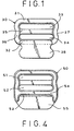
- each cup is provided with an adjustable strap assembly 17 or 18.
- Each of the assemblies includes a slider 19 and a shoulder strap segment 20 which is movable through the slider and has a segment 21 passing through a ring 22 and affixed to the slider 19, as will be described in greater detail hereinafter.
- the slider body is in the form of a frame having longitudinal limbs or bars 31 and 32 defining oval slots 33 and 34 with a cross bar 35 bridging the transverse limbs 36 and 37 of the frame.
- the bar or limb 32 is formed with a sewing flange 38 which abuts a step 39 and receives a free of the strap segment 40, running to the ring, e.g. the ring 22.
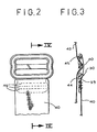
- the slider is injection molded polyoxymethylene and, as can be seen from FIG. 3, the transverse limbs 36 and 37 can rise from the thickness of the bar 31 or 32 to the center region at which it may be almost twice the thickness of the cross bar 35, the center region being shown at 41 in FIG. 2.
- the other strap segment 43 passes through the slot 33 from the side 44 of the frame turned toward the body, is then looped round the cross bar 35 and passes out through the slot 34 to lie along the aforementioned side of the sewing flange 38.
- the sewing flange 38 may have a thickness of 0.6 mm while the overall thickness of the slide may be 1.8 mm.
- the slide may have a ridge 45 along the slot 43.
- the strap segment 40 is stitched through the sewing flange and is therefore secured thereto by rows 46 of stitches.
- the strap segment 43 does not pass around any bulked up or looped portion of the strap segment 40 which, in earlier strap systems may have been looped around one of the slide limbs or the cross bar so that the bulk attributable to multiple thicknesses of the strap is avoided in the flat one layer slide with the sewing flange of FIGS. 1-3.
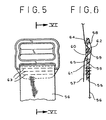
- FIGS. 4-6 show a similar construction wherein, however, the slide 50, in addition to the oval openings 51 and 52, has a further opening 53 below the cross bar 54. This opening 53 is provided between the sewing flange 55 and the bar 54.
- the strap segment 56 can be passed through the slot 53 and thus can lie along both flanks of the sewing flange 55 to which the strap segment is stitched through.
- the adjustable shoulder strap section 57 passes through the slot 58 and around the cross bar 59 before passing out through the slot 60.
- the cross bar 59 is offset toward the side 61 of the slide so that the loop 62 of the strap section 57 remains wholly within the thickness of the slide.
- the stitching of the strap section 56 here passes through two thicknesses thereof and the sewing flange.
- ridges 64 and 65 are provided along the bars 51 and 54 to engage the strap section 57 when the latter is under tension and to assist in retaining the slide in position along the strap section 57.
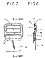
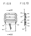
- FIGS. 7 and 8 illustrate an embodiment of the invention wherein the frame 70 is completely flat along the side 71 so that sharp edges at 72 and 73 of the longitudinal limbs 74 and 75 can bite into the strap section 71 to held the strap and the slider against undesired slip.
- the strap section 76 is passed through the slot 77 above the sewing flange 78 and then loops around the latter so that the stitching 79 passes through a turned over portion of the strap in addition to the sewing flange 78.
- the strap section 80 is connected to the sewing flange 81 by stitchings 82 and 83 while the strap section 84 passes through the slot 85, around the cross bar 86 and out through the slot 87 along the limb 88.
- Ridges 89 play the same role here as the ridges of the two previous embodiments.
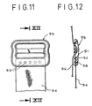
- the lower limb 91 is formed with a welding flange 92 instead of with a sewing flange.
- the welding flange 92 can be provided with a row of projections 93 which can engage in the strap section 94 during the welding process.
- the slide 95 is otherwise similar to that described, except that it is formed with a compartment 96 in which the strap section 94 engages.
- the fabric is thermally welded to the slider in the recess 96 and thus is permanently secured thereto.
- the flat slide tends to remain in position and does not tend to cock to one side or another. It can make use of other methods of attaching the strap sections to the slider.
- the surface 98 of the flange 92 which is exposed in the embodiment illustrated, can be embossed with legible matter, for example promoting the flat slide of the invention, or of a decorative nature.
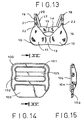
- FIGS. 14 to 17 illustrate an embodiment of the invention in which the slide 100, as in previous embodiments, has slots 101 and 102 but wherein the flange 103 is overhung by an end protecting roof 104.
- the central bar 105 is here offset toward the side 106 of the slide which is to lie along the body.
- An end 107 of the strap can be stitched or otherwise attached to the flange 103 so that the free end 108 of this strap segment 107 is hung by the roof 104 and protected against fraying thereby.
- the strap from the segment 107 passes through the ring 109 which is attached to the brassiere and then along the body side 106 of the slide 100, around the bar 105 and out through the slot 101.
- both the front 110 of the strap and the back 111 can be visible from the side of the strap opposite the body side.
- the appearance of two sides of the strap can be unesthetic.
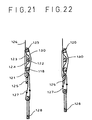
- this slide can be threaded with the strap 126 so that, from the sewing flange 125, a segment 127 passes downwardly through the ring 128 and then upwardly through the auxiliary slot 121, behind the bar 128, through the slot 124, around the bar 122, through the slot 123 and around the bar 129. Only the front side 130 of the strap is visible from the side opposite the body side.
- the segment 127 is affixed to the sewing flange 125 and the strap passes around the ring 128 to thread through the slider 120 in the same pattern as in FIG. 21 so that only the front 130 of the strap is visible.
Landscapes
- Engineering & Computer Science (AREA)
- Textile Engineering (AREA)
- Corsets Or Brassieres (AREA)
- Closures For Containers (AREA)
Claims (17)
- Eine Tragriemen-Spange für Wäsche aufweisend:eine Spange (30), die einen Rahmen, der durch ein Paar von parallelen äußeren Gliedern (31,32), Quergliedern (36,37), welche die äußeren Glieder (31,32) an den hiervon gegenüberliegenden Enden verbinden, entsprechende Schlitze (33,34) entlang jedem der äußeren Glieder (31,32), einen Querstab (35), der die Querglieder (36,37) zwischen den Schlitzen (33,34) verbindet und einem Flansch (38) besitzt, der benachbart zu einem der äußeren Gliedern (31,32) ist, wobei der Querstab (35) dünner als die äußeren Glieder (31,32) ist, dadurch gekennzeichnet, dassdie Schlitze (33,34) entlang jedem der äußeren Gliedern (31,32) oval sind, der Rahmen eine Seite, die geeignet ist, um zum Körper eines Trägers hin gedreht zu werden, und eine Seite, die geeignet ist, um vom Körper des Trägers weg gedreht zu werden, besitzt, und der Querstab (35) zu einer der Seiten hin versetzt ist.
- Tragriemen-Spange gemäß Anspruch 1, wobei der Flansch ein Nähflansch ist, an dem ein Riemensegment durch Nähen durch den Flansch und das hieran befestigte Riemensegment befestigt werden kann.
- Tragriemen-Spange gemäß Anspruch 1, wobei der Flansch eine Stufe benachbart zu dem einen der äußeren Glieder bildet.
- Tragriemen-Spange gemäß Anspruch 1, wobei der Flansch einen weiteren Schlitz zwischen dem Flansch und dem einen der äußeren Glieder bestimmt.
- Tragriemen-Spange gemäß Anspruch 1, wobei der Flansch ein Schweißflansch ist, an dem ein Riemensegment durch Schweißen des Riemensegments an den Flansch befestigt werden kann.
- Tragriemen-Spange gemäß Anspruch 5, wobei der Flansch Projektionen besitzt an denen das Riemensegment geheftet werden kann, um an dem Flansch befestigt zu werden.
- Tragriemen-Spange gemäß Anspruch 1, wobei der Flansch mit einer Ausnehmung gebildet ist, die zu der einen Seite hin geöffnet ist, um ein Riemensegment, das an dem Flansch befestigt werden soll, aufzunehmen.
- Tragriemen-Spange gemäß Anspruch 7, wobei der Flansch eine Flanke auf einer seiner Seite gegenüber der Ausnehmung besitzt und ein hierauf geprägtes Muster besitzt.
- Tragriemen-Spange gemäß Anspruch 1, wobei die Querglieder in ihrer Stärke von den äußeren Gliedern in Richtung zum Querstab hin wachsen.
- Tragriemen-Spange gemäß Anspruch 1, wobei der Rahmen auf der ersten Seite vollkommen flach ist.
- Tragriemen-Spange gemäß Anspruch 1, wobei die äußeren Glieder scharfe Ränder besitzen, die an die jeweiligen Schlitze auf der ersten Seite angrenzen.
- Tragriemen-Spange gemäß Anspruch 1, wobei die äußeren Glieder Kanten besitzen, die aus der ersten Seite benachbart zu den jeweiligen Schlitze herausragen.
- Eine einstellbare Riemenanordnung für Wäsche, die eine Tragriemen-Spange gemäß Anspruch 1-12 aufweist, die weiterhin aufweist Riemenmittel zur Einstellung relative zur Spange, wobei die Riemenmittel ein Riemensegment beinhalten, das durch einen der Schlitze von einer ersten der Seiten durch um den Querstab herum und durch den anderen der Schlitze auf der ersten der Seiten hinausführt, und Mittel zum Befestigen eines anderen Riemensegments an dem Flansch.
- Anordnung gemäß Anspruch 13, wobei eines der Glieder einen Überhang besitzt, das ein freies Ende des anderen Riemensegments gegen den Träger schützt.
- Anordnung gemäß Anspruch 13 weiterhin aufweisend einen zusätzlichen Schlitz, der in der Spange zwischen einem der äußeren Glieder und dem Flansch gebildet ist, wobei die Riemenmittel nur eine Seite besitzen, die von der Seite, welche angebracht ist, um vom Träger weg gedreht zu werden, exponierte wird.
- Anordnung gemäß Anspruch 15, wobei die exponierte Seite der Riemenmittel eine glänzende Seite ist.
- Anordnung gemäß Anspruch 13, wobei die Riemenmittel Schulterriemen eines Büstenhalters sind.
Applications Claiming Priority (2)
| Application Number | Priority Date | Filing Date | Title |
|---|---|---|---|
| US363057 | 1999-07-29 | ||
| US09/363,057 US6056626A (en) | 1999-07-29 | 1999-07-29 | Flat slide assembly for lingerie |
Publications (2)
| Publication Number | Publication Date |
|---|---|
| EP1072203A1 EP1072203A1 (de) | 2001-01-31 |
| EP1072203B1 true EP1072203B1 (de) | 2004-06-09 |
Family
ID=23428609
Family Applications (1)
| Application Number | Title | Priority Date | Filing Date |
|---|---|---|---|
| EP00114777A Expired - Lifetime EP1072203B1 (de) | 1999-07-29 | 2000-07-10 | Flacher verstellbarer Verschluss für Wäsche |
Country Status (4)
| Country | Link |
|---|---|
| US (1) | US6056626A (de) |
| EP (1) | EP1072203B1 (de) |
| AT (1) | ATE268555T1 (de) |
| DE (1) | DE60011351T2 (de) |
Cited By (1)
| Publication number | Priority date | Publication date | Assignee | Title |
|---|---|---|---|---|
| WO2016175805A1 (en) * | 2015-04-29 | 2016-11-03 | North Carolina State University | Strap adjuster for a bra |
Families Citing this family (27)
| Publication number | Priority date | Publication date | Assignee | Title |
|---|---|---|---|---|
| US6499201B2 (en) * | 2001-01-25 | 2002-12-31 | Fildan Accessories Corporation | Garment fastener especially for swimwear and lingerie |
| US6368180B1 (en) * | 2001-01-26 | 2002-04-09 | Sandra Dailey | System for repairing a brassiere |
| USD526481S1 (en) | 2003-03-03 | 2006-08-15 | Xm International, Inc. | Container |
| US6904648B2 (en) * | 2003-05-13 | 2005-06-14 | Fildan Accessories Corporation | Strap assembly for lingerie and brassieres |
| US20050045635A1 (en) * | 2003-09-03 | 2005-03-03 | Jane Dong | Containers for storing articles |
| US7140080B2 (en) * | 2005-04-14 | 2006-11-28 | Fildan Accessories Corporation | Lingerie strap slide assembly |
| US20070212975A1 (en) * | 2006-03-09 | 2007-09-13 | Ausman Susan W | Hook-and-Loop Type Brassiere Fastener |
| US7318240B1 (en) | 2006-03-24 | 2008-01-15 | Nicole Rendone | One piece undergarment bodysuit |
| ITTO20060531A1 (it) * | 2006-07-19 | 2008-01-20 | Nat Molding Europ S R L | Procedimento per la fabbricazione di un dispositivo di accoppiamento quale una fibbia o un sistema di regolazione di nastri, particolarmente per zaini, borse e simili, e fibbia e sistema di regolazione di nastri realizzabili mediante tale procediment |
| US8393016B2 (en) * | 2007-02-22 | 2013-03-12 | Isabelt Ltd. | Discreet elastic belt |
| US8671526B2 (en) * | 2008-11-17 | 2014-03-18 | Jet 21, Inc. | String covering apparatus |
| KR101016882B1 (ko) * | 2009-01-08 | 2011-02-22 | 백지숙 | 스트랩 조절구 |
| GB0918433D0 (en) | 2009-10-21 | 2009-12-09 | Kis Ltd | Adjustable strap assembly,slider and connector |
| US8469147B2 (en) * | 2010-01-21 | 2013-06-25 | Mine Safety Appliances Company | Chest strap arrangement for an attachable arrangement |
| US20110284321A1 (en) * | 2010-05-20 | 2011-11-24 | Jacob Hall | Adjustable harness leg loop |
| US8631515B2 (en) * | 2010-10-26 | 2014-01-21 | Nike, Inc. | Bikini top with friction locking cord adjustment system |
| USD712306S1 (en) * | 2013-05-23 | 2014-09-02 | Fildan Accessories (Hk) Ltd. | Lingerie slide |
| US10188154B2 (en) * | 2016-05-31 | 2019-01-29 | Michael D. Beattie | Brassiere underwire repair device |
| USD821259S1 (en) * | 2017-02-28 | 2018-06-26 | Thompson-Weiler Enterprises, LLC | Buckle |
| US20190029329A1 (en) * | 2017-07-28 | 2019-01-31 | Regina Miracle International (Group) Limited | New shoulder strap |
| USD883139S1 (en) * | 2018-04-05 | 2020-05-05 | Dubrosky & Tracy Patent Services Corp. | Slide for a strap |
| USD883856S1 (en) * | 2018-04-05 | 2020-05-12 | Dubrosky & Tracy Patent Services Corp. | Link for a strap |
| USD1016665S1 (en) * | 2019-08-28 | 2024-03-05 | Fullbeauty Brands Operations, Llc | Tribar slider |
| USD1017460S1 (en) * | 2019-08-28 | 2024-03-12 | Fullbeauty Brands Operations, Llc | Tribar slider |
| USD885254S1 (en) * | 2019-11-05 | 2020-05-26 | Dongguan Huajin Gifts Co., Ltd. | Harness buckle |
| USD909225S1 (en) | 2019-11-08 | 2021-02-02 | Fitbit, Inc. | Set of bands for a watch or smart watch |
| USD1026728S1 (en) * | 2023-01-04 | 2024-05-14 | Ningbo Giga Fall Protection Equipment Co., Ltd. | Buckle |
Family Cites Families (16)
| Publication number | Priority date | Publication date | Assignee | Title |
|---|---|---|---|---|
| US2224773A (en) * | 1940-06-22 | 1940-12-10 | Shaulson Joseph | Buckle |
| US2260060A (en) * | 1940-12-09 | 1941-10-21 | Shaulson Joseph | Buckle connection |
| US3077650A (en) * | 1958-05-07 | 1963-02-19 | Singing Needles Inc | Adjustable shoulder straps |
| US3112750A (en) * | 1960-07-19 | 1963-12-03 | Sobel Metal Products Inc | Garment having adjustable plastic buckle |
| US3075268A (en) * | 1961-02-09 | 1963-01-29 | S & S Ind Inc | Adjusting strap buckle |
| US3164154A (en) * | 1962-06-22 | 1965-01-05 | Carl G Simonsen | Brassiere |
| US3161931A (en) * | 1962-11-08 | 1964-12-22 | Maidenform Inc | Brassiere shoulder strap buckle |
| US3115878A (en) * | 1962-12-20 | 1963-12-31 | Grace H Markham | Brassiere shoulder strap |
| US3290696A (en) * | 1964-07-16 | 1966-12-06 | Fashion Dev Corp | Straps |
| GB1343131A (en) * | 1971-02-24 | 1974-01-10 | Courtaulds Ltd | Adjustable shoulder strap |
| BE1002358A5 (nl) * | 1988-08-16 | 1991-01-08 | Confect Schockaert Bv Met Bepe | Verbeterde gesp. |
| US5590443A (en) * | 1995-05-31 | 1997-01-07 | Fildan; Gerhard | Nonslip slide buckle |
| US5661878A (en) * | 1996-07-22 | 1997-09-02 | Net/Werk/Usa, Inc. | Strapping system and buckle therefor |
| US5848454A (en) * | 1996-11-12 | 1998-12-15 | Kojima; Kimberly | Strapping system and fastener therefor |
| US5971834A (en) * | 1998-01-06 | 1999-10-26 | Murray; Michael D. | Adjustable support bra and method of making |
| JP3454713B2 (ja) * | 1998-05-11 | 2003-10-06 | Ykk株式会社 | ベルト連結具 |
-
1999
- 1999-07-29 US US09/363,057 patent/US6056626A/en not_active Expired - Lifetime
-
2000
- 2000-07-10 DE DE60011351T patent/DE60011351T2/de not_active Expired - Fee Related
- 2000-07-10 AT AT00114777T patent/ATE268555T1/de not_active IP Right Cessation
- 2000-07-10 EP EP00114777A patent/EP1072203B1/de not_active Expired - Lifetime
Cited By (1)
| Publication number | Priority date | Publication date | Assignee | Title |
|---|---|---|---|---|
| WO2016175805A1 (en) * | 2015-04-29 | 2016-11-03 | North Carolina State University | Strap adjuster for a bra |
Also Published As
| Publication number | Publication date |
|---|---|
| DE60011351D1 (de) | 2004-07-15 |
| EP1072203A1 (de) | 2001-01-31 |
| US6056626A (en) | 2000-05-02 |
| DE60011351T2 (de) | 2005-07-28 |
| ATE268555T1 (de) | 2004-06-15 |
Similar Documents
| Publication | Publication Date | Title |
|---|---|---|
| EP1072203B1 (de) | Flacher verstellbarer Verschluss für Wäsche | |
| US6163937A (en) | Bra strap converter | |
| US3506978A (en) | Reversible tie construction | |
| US4121305A (en) | Panties | |
| US6173449B1 (en) | One-piece women's sunbathing beach and swim suit | |
| US20030186617A1 (en) | Brassiere, mainly for use when nursing | |
| US7140080B2 (en) | Lingerie strap slide assembly | |
| JP4204627B2 (ja) | 腹巻 | |
| US7234995B2 (en) | D-ring for brassieres and the like | |
| US6321419B1 (en) | Brassiere fastener | |
| US20080045122A1 (en) | Clothes with Back Part Such as Brassiere | |
| US6715155B2 (en) | Pair of pants equipped with a tightening strap | |
| US6309489B1 (en) | Adjustable strap fastener for brassieres and the like and method of making same | |
| US6553578B2 (en) | Protective garment | |
| US6513209B1 (en) | Fastening system for a bra | |
| US3489153A (en) | Garment with readily adjustable and replaceable shoulder straps | |
| US4771481A (en) | Holder for pre-knotted neckties | |
| US2481367A (en) | Necktie | |
| EP1101418A2 (de) | Verstellbare Befestigungseinrichtung für Büstenhalter und Herstellungsverfahren | |
| US20200329797A1 (en) | Adjustable clothing cincher | |
| US6347438B1 (en) | Brassiere fastener | |
| CN217791586U (zh) | 扣环件 | |
| US20190125014A1 (en) | Headband with Infinity Scarf | |
| US2568670A (en) | Adjustable shoulder strap for undergarments | |
| CN210672132U (zh) | 一种束腹下装 |
Legal Events
| Date | Code | Title | Description |
|---|---|---|---|
| PUAI | Public reference made under article 153(3) epc to a published international application that has entered the european phase |
Free format text: ORIGINAL CODE: 0009012 |
|
| AK | Designated contracting states |
Kind code of ref document: A1 Designated state(s): AT BE CH CY DE DK ES FI FR GB GR IE IT LI LU MC NL PT SE |
|
| AX | Request for extension of the european patent |
Free format text: AL;LT;LV;MK;RO;SI |
|
| 17P | Request for examination filed |
Effective date: 20010612 |
|
| AKX | Designation fees paid |
Free format text: AT BE CH CY DE DK ES FI FR GB GR IE IT LI LU MC NL PT SE |
|
| 17Q | First examination report despatched |
Effective date: 20030311 |
|
| GRAP | Despatch of communication of intention to grant a patent |
Free format text: ORIGINAL CODE: EPIDOSNIGR1 |
|
| GRAS | Grant fee paid |
Free format text: ORIGINAL CODE: EPIDOSNIGR3 |
|
| GRAA | (expected) grant |
Free format text: ORIGINAL CODE: 0009210 |
|
| AK | Designated contracting states |
Kind code of ref document: B1 Designated state(s): AT BE CH CY DE DK ES FI FR GB GR IE IT LI LU MC NL PT SE |
|
| PG25 | Lapsed in a contracting state [announced via postgrant information from national office to epo] |
Ref country code: NL Free format text: LAPSE BECAUSE OF FAILURE TO SUBMIT A TRANSLATION OF THE DESCRIPTION OR TO PAY THE FEE WITHIN THE PRESCRIBED TIME-LIMIT Effective date: 20040609 Ref country code: LI Free format text: LAPSE BECAUSE OF FAILURE TO SUBMIT A TRANSLATION OF THE DESCRIPTION OR TO PAY THE FEE WITHIN THE PRESCRIBED TIME-LIMIT Effective date: 20040609 Ref country code: FI Free format text: LAPSE BECAUSE OF FAILURE TO SUBMIT A TRANSLATION OF THE DESCRIPTION OR TO PAY THE FEE WITHIN THE PRESCRIBED TIME-LIMIT Effective date: 20040609 Ref country code: ES Free format text: LAPSE BECAUSE OF FAILURE TO SUBMIT A TRANSLATION OF THE DESCRIPTION OR TO PAY THE FEE WITHIN THE PRESCRIBED TIME-LIMIT Effective date: 20040609 Ref country code: CY Free format text: LAPSE BECAUSE OF FAILURE TO SUBMIT A TRANSLATION OF THE DESCRIPTION OR TO PAY THE FEE WITHIN THE PRESCRIBED TIME-LIMIT Effective date: 20040609 Ref country code: CH Free format text: LAPSE BECAUSE OF FAILURE TO SUBMIT A TRANSLATION OF THE DESCRIPTION OR TO PAY THE FEE WITHIN THE PRESCRIBED TIME-LIMIT Effective date: 20040609 Ref country code: BE Free format text: LAPSE BECAUSE OF FAILURE TO SUBMIT A TRANSLATION OF THE DESCRIPTION OR TO PAY THE FEE WITHIN THE PRESCRIBED TIME-LIMIT Effective date: 20040609 Ref country code: AT Free format text: LAPSE BECAUSE OF FAILURE TO SUBMIT A TRANSLATION OF THE DESCRIPTION OR TO PAY THE FEE WITHIN THE PRESCRIBED TIME-LIMIT Effective date: 20040609 |
|
| REG | Reference to a national code |
Ref country code: GB Ref legal event code: FG4D |
|
| REG | Reference to a national code |
Ref country code: CH Ref legal event code: EP |
|
| PG25 | Lapsed in a contracting state [announced via postgrant information from national office to epo] |
Ref country code: LU Free format text: LAPSE BECAUSE OF NON-PAYMENT OF DUE FEES Effective date: 20040710 |
|
| PG25 | Lapsed in a contracting state [announced via postgrant information from national office to epo] |
Ref country code: IE Free format text: LAPSE BECAUSE OF NON-PAYMENT OF DUE FEES Effective date: 20040712 |
|
| REF | Corresponds to: |
Ref document number: 60011351 Country of ref document: DE Date of ref document: 20040715 Kind code of ref document: P |
|
| REG | Reference to a national code |
Ref country code: IE Ref legal event code: FG4D |
|
| PG25 | Lapsed in a contracting state [announced via postgrant information from national office to epo] |
Ref country code: MC Free format text: LAPSE BECAUSE OF NON-PAYMENT OF DUE FEES Effective date: 20040731 |
|
| PG25 | Lapsed in a contracting state [announced via postgrant information from national office to epo] |
Ref country code: SE Free format text: LAPSE BECAUSE OF FAILURE TO SUBMIT A TRANSLATION OF THE DESCRIPTION OR TO PAY THE FEE WITHIN THE PRESCRIBED TIME-LIMIT Effective date: 20040909 Ref country code: GR Free format text: LAPSE BECAUSE OF FAILURE TO SUBMIT A TRANSLATION OF THE DESCRIPTION OR TO PAY THE FEE WITHIN THE PRESCRIBED TIME-LIMIT Effective date: 20040909 Ref country code: GB Free format text: LAPSE BECAUSE OF NON-PAYMENT OF DUE FEES Effective date: 20040909 Ref country code: DK Free format text: LAPSE BECAUSE OF FAILURE TO SUBMIT A TRANSLATION OF THE DESCRIPTION OR TO PAY THE FEE WITHIN THE PRESCRIBED TIME-LIMIT Effective date: 20040909 |
|
| NLV1 | Nl: lapsed or annulled due to failure to fulfill the requirements of art. 29p and 29m of the patents act | ||
| REG | Reference to a national code |
Ref country code: CH Ref legal event code: PL |
|
| ET | Fr: translation filed | ||
| REG | Reference to a national code |
Ref country code: IE Ref legal event code: MM4A |
|
| PGFP | Annual fee paid to national office [announced via postgrant information from national office to epo] |
Ref country code: FR Payment date: 20050415 Year of fee payment: 6 |
|
| PLBE | No opposition filed within time limit |
Free format text: ORIGINAL CODE: 0009261 |
|
| STAA | Information on the status of an ep patent application or granted ep patent |
Free format text: STATUS: NO OPPOSITION FILED WITHIN TIME LIMIT |
|
| GBPC | Gb: european patent ceased through non-payment of renewal fee |
Effective date: 20040909 |
|
| 26N | No opposition filed |
Effective date: 20050310 |
|
| PGFP | Annual fee paid to national office [announced via postgrant information from national office to epo] |
Ref country code: DE Payment date: 20050725 Year of fee payment: 6 |
|
| PGFP | Annual fee paid to national office [announced via postgrant information from national office to epo] |
Ref country code: IT Payment date: 20060731 Year of fee payment: 7 |
|
| PG25 | Lapsed in a contracting state [announced via postgrant information from national office to epo] |
Ref country code: DE Free format text: LAPSE BECAUSE OF NON-PAYMENT OF DUE FEES Effective date: 20070201 |
|
| REG | Reference to a national code |
Ref country code: FR Ref legal event code: ST Effective date: 20070330 |
|
| PG25 | Lapsed in a contracting state [announced via postgrant information from national office to epo] |
Ref country code: PT Free format text: LAPSE BECAUSE OF NON-PAYMENT OF DUE FEES Effective date: 20041109 |
|
| PG25 | Lapsed in a contracting state [announced via postgrant information from national office to epo] |
Ref country code: FR Free format text: LAPSE BECAUSE OF NON-PAYMENT OF DUE FEES Effective date: 20060731 |
|
| PG25 | Lapsed in a contracting state [announced via postgrant information from national office to epo] |
Ref country code: IT Free format text: LAPSE BECAUSE OF NON-PAYMENT OF DUE FEES Effective date: 20070710 |